EP3895861A1 - Rasiervorrichtung - Google Patents
Rasiervorrichtung Download PDFInfo
- Publication number
- EP3895861A1 EP3895861A1 EP20169937.8A EP20169937A EP3895861A1 EP 3895861 A1 EP3895861 A1 EP 3895861A1 EP 20169937 A EP20169937 A EP 20169937A EP 3895861 A1 EP3895861 A1 EP 3895861A1
- Authority
- EP
- European Patent Office
- Prior art keywords
- bevel
- face
- cutting
- shaving device
- angle
- Prior art date
- Legal status (The legal status is an assumption and is not a legal conclusion. Google has not performed a legal analysis and makes no representation as to the accuracy of the status listed.)
- Withdrawn
Links
Images


Classifications
-
- B—PERFORMING OPERATIONS; TRANSPORTING
- B26—HAND CUTTING TOOLS; CUTTING; SEVERING
- B26B—HAND-HELD CUTTING TOOLS NOT OTHERWISE PROVIDED FOR
- B26B21/00—Razors of the open or knife type; Safety razors or other shaving implements of the planing type; Hair-trimming devices involving a razor-blade; Equipment therefor
- B26B21/54—Razor-blades
- B26B21/56—Razor-blades characterised by the shape
-
- B—PERFORMING OPERATIONS; TRANSPORTING
- B26—HAND CUTTING TOOLS; CUTTING; SEVERING
- B26B—HAND-HELD CUTTING TOOLS NOT OTHERWISE PROVIDED FOR
- B26B21/00—Razors of the open or knife type; Safety razors or other shaving implements of the planing type; Hair-trimming devices involving a razor-blade; Equipment therefor
- B26B21/40—Details or accessories
- B26B21/4012—Housing details, e.g. for cartridges
- B26B21/4031—Housing details, e.g. for cartridges characterised by special geometric shaving parameters, e.g. blade span or exposure
-
- B—PERFORMING OPERATIONS; TRANSPORTING
- B26—HAND CUTTING TOOLS; CUTTING; SEVERING
- B26B—HAND-HELD CUTTING TOOLS NOT OTHERWISE PROVIDED FOR
- B26B21/00—Razors of the open or knife type; Safety razors or other shaving implements of the planing type; Hair-trimming devices involving a razor-blade; Equipment therefor
- B26B21/54—Razor-blades
- B26B21/58—Razor-blades characterised by the material
Definitions
- the present invention relates to a shaving device for shaving a skin surface comprising a housing with a skin contacting surface and at least one cutting blade mounted in the housing, wherein the at least one cutting blade has an asymmetric cross-sectional shape with a first face, a second face opposed to the first face as well as a cutting edge at the intersection of the first face and the second face.
- US 3,863,340 teaches a plural edge razor with a lead blade member and a following blade member, wherein the members have unsymmetrical edges hereon and have passages therethrough to facilitate removal of shaving debris from the cutting edge.
- US 6,655,030 describes a shaving head with at least a first and second cutting member arranged behind and spaced apart from the first cutting member wherein the cutting angle between the skin contacting surface and the second cutting member is equal or higher than the cutting angle between the skin contacting surface of the first cutting member.
- US 3,842,499 refers to a razor blade assembly with one or more groups of multiple cutting edge wherein the group of cutting elements comprises at least two blades with one blade being chisel shaped. This allows a favorable geometry for tandem blade shaving operations.
- the dimensions of shaving blade edge profiles and their arrangement in a shaving device are interdependent and are typically optimized to cut hair efficiently. This comprises the following 3 parameters:
- the first two parameters result in a comfortable shave without tugging on the hairs while they are cut.
- the small tip radius of the edge together with a large blade mounting angle i.e. the clearance angle ⁇ , creates a significant pressure onto the skin surface, which is uncomfortable and may even lead to skin being cut. Reducing the effective cutting angle ⁇ improves the safety during shaving.
- conventional symmetric wedge-shaped blades tend to ride over the hair without penetrating and cutting through.
- the rake face interacts with the hair and is primarily responsible for the hair cutting performance while the clearance face interacts with the skin and is primarily responsible for the safety of the skin.
- the clearance angle ⁇ should be as small as possible to ensure skin safety and the effective cutting angle ⁇ should be as large as possible to efficiently cut through the hair.
- the clearance angle ⁇ plays the role of the safety angle and the effective cutting angle ⁇ plays the role of the efficiency angle.
- an asymmetric cutting blade profile with at least one additional cutting bevel is disclosed.
- the present invention therefore addresses the mentioned drawbacks in the prior art and provides a shaving device with an optimized geometrical setup allowing a low cutting force and a high cutting efficiency and ensuring sufficient safety for the skin.
- intersecting line has to be understood as the linear extension of an intersecting point (according to a cross-sectional view as in Fig. 3 ) between different bevels regarding the perspective view (as in Fig. 1 ).
- intersecting point is extended to an intersecting line in the perspective view.
- a shaving device for shaving a skin surface comprising a housing with a skin contacting surface and at least one cutting blade mounted in the housing, wherein the at least one cutting blade has an asymmetric cross-sectional shape with a first face and opposed to the first face a second face as well as a cutting edge at the intersection of the first face and the second face, wherein
- the at least one cutting blade is mounted in the housing that the following conditions are met:
- the at least one cutting blade has an asymmetric cross-sectional shape.
- the asymmetrical cross-sectional shape refers to the symmetry with respect to an axis which is the bisecting line of ( ⁇ 1 + ⁇ 2 )/2 and anchored at the cutting edge.
- the at least one cutting blade according to the present invention has a low cutting force due to a smaller ⁇ 2 while the cutting efficiency is high which is realized by a larger effective cutting angle ⁇ . Moreover, the shaving device has an increased safety of the shaving process due to the small clearance angle ⁇ .
- the primary bevel may have the additional function to strengthen the cutting blade if the primary wedge angle is larger than the secondary wedge angle which allows a mechanical stabilization against damage from the cutting operation which allows a slim blade body in the area of the secondary bevel without affecting the cutting performance of the blade.
- the primary bevel with the first wedge angle ⁇ 1 has therefore the function of a stabilizing angle of the cutting edge preventing damage to the cutting edge when a hair is being cut, i.e. a bigger wedge angle ⁇ 1 increases the mechanical stability of the cutting edge. In consequence, by using a primary bevel with the wedge angle ⁇ 1 the second wedge angle ⁇ 2 can be reduced.
- the wedge angle ⁇ 1 has the function to stabilize the cutting edge which allows a slim blade body in the area of the secondary bevel without effecting the cutting performance of the blade. Moreover, the primary bevel with the wedge angle ⁇ 1 allows to lift the cutting edge from the object to be cut which makes the cutting step safer, e.g. by raising the distance between skin and cutting edge a cutting into the skin can be avoided.
- the second wedge angle ⁇ 2 represents the penetration angle of the blade penetrating in the object being cut. The smaller the penetrating angle ⁇ 2 , the lower the force to penetrate the object being cut.
- the clearance angel ⁇ is ⁇ 5°, preferably ⁇ 1°, more preferably ⁇ 0° and even more preferably from -1° to -5° and/or the effective cutting angle first wedge angle ⁇ is ⁇ 15°, preferably ⁇ 20°.
- the first wedge angle ⁇ 1 ranges from 5° to 75°, preferably 10° to 60°, more preferably 15° to 45° and/or the second wedge angle ⁇ 2 ranges from -5° to 40°, preferably 0° to 30°, more preferably 10° to 25°.
- the cutting blades according to the present invention are preferably further strengthened by adding a thick and strong tertiary bevel that has a tertiary wedge angle greater than the secondary wedge angle and by employing this tertiary bevel to split the object to be cut, thus reducing the forces acting on the thin secondary bevel.
- the third wedge angle ⁇ 3 ranges preferably from 1° to 60°, more preferably from 10° to 55°, even more preferably from 19° to 46°, and in particular from 20° to 45°
- the third wedge angle ⁇ 3 represents the splitting angle, i.e. the angle necessary to split the object to be cut.
- the third wedge angle ⁇ 3 has to be preferably larger than the second wedge angle ⁇ 2 .
- the primary bevel has a length d 1 being the dimension projected onto the first surface of the length taken from the cutting edge to the first intersecting line from 0.1 to 7 ⁇ m, preferably from 0.5 to 5 ⁇ m, and more preferably 1 to 3 ⁇ m.
- a length d 1 ⁇ 0.1 ⁇ m is difficult to realize since an edge of such length is too fragile and would not allow a stable use of the cutting blade.
- the primary bevel stabilizes the blade body with the secondary and tertiary bevel which allows a slim blade in the area of the secondary bevel which offers a low cutting force.
- the primary bevel does not affect the cutting performance provided the length d 1 is not larger than 7 ⁇ m.
- the length d 2 being the dimension projected onto the first surface (i.e. the projection of the primary and secondary bevel) taken from the cutting edge to the second intersecting line ranges from 1 to 100 ⁇ m, more preferably from 5 to 75 ⁇ m, and even more preferably from 10 to 50 ⁇ m.
- the length d 2 corresponds to the penetration depth of the cutting blade in the object to be cut.
- d 2 corresponds to at least 30% of the diameter of the object to be cut, i.e. when the object is human hair which typically has a diameter of around 100 ⁇ m the length d 2 is around 30 ⁇ m.
- the cutting blade is preferably defined by a blade body comprising or consisting of a first material and a second material joined with the first material.
- the second material can be deposited as a coating at least in regions of the first material, i.e. the second material can be an enveloping coating of the first material or a coating deposited on the first material on the first face.
- the material of the first material is in general not limited to any specific material as long it is possible to bevel this material.
- the blade body consists only of the first material, i.e. an uncoated first material.
- the first material is preferably a material with an isotropic structure, i.e. having identical values of a property in all directions.
- isotropic materials are often better suited for shaping, independent from the shaping technology.
- the first material comprises or consists of a material selected from the group consisting of
- the second material comprises or consists of a material selected from the group consisting of
- VDI guideline 2840 can be chosen for the second material.
- a second material of nano-crystalline diamond and/or multilayers of nano-crystalline and polycrystalline diamond is suppressed.
- cutting blades having a second material of nano-crystalline diamond layers, detachment, as is known of polycrystalline diamond is suppressed.
- monocrystalline diamond it has been shown that production of nano-crystalline diamond, compared to the production of monocrystalline diamond, can be accomplished substantially more easily and economically. Hence, also longer and larger-area cutting blades can be provided.
- nano-crystalline diamond layers are more homogeneous than polycrystalline diamond layers, the material also shows less inherent stress. Consequently, macroscopic distortion of the cutting edge is less probable.
- the second material has a thickness of 0.15 to 20 ⁇ m, preferably 2 to 15 ⁇ m and more preferably 3 to 12 ⁇ m.
- the second material has a modulus of elasticity (Young's modulus) of less than 1,200 GPa, preferably less than 900, and more preferably less than 750 GPa. Due to the low modulus of elasticity the hard coating becomes more flexible and more elastic and may be better adapted to the substrate, object or the contour to be cut.
- the Young's modulus is determined according to the method as disclosed in Markus Mohr et al., "Youngs modulus, fracture strength, and Poisson's ratio of nanocrystalline diamond films", J. Appl. Phys. 116, 124308 (2014 ), in particular under paragraph III. B. Static measurement of Young's modulus.
- the second material has preferably a transverse rupture stress ⁇ 0 of at least 1 GPa, more preferably of at least 2.5 GPa, and even more preferably at least 5 GPa.
- the transverse rupture stress ⁇ 0 is thereby determined by statistical evaluation of breakage tests, e.g. in the B3B load test according to the above literature details. It is thereby defined as the breaking stress at which there is a probability of breakage of 63%.
- the second material has preferably a hardness of at least 20 GPa.
- the hardness is determined by nanoindentation ( Yeon-Gil Jung et. al., J. Mater. Res., Vol. 19, No. 10, p. 3076 ).
- the surface roughness R RMS is determined according to DIN EN ISO 25178. The mentioned surface roughness makes additional mechanical polishing of the grown second material superfluous.
- the second material has an average grain size d 50 of the nano-crystalline diamond of 1 to 100 nm, preferably 5 to 90 nm and more preferably from 7 to 30 nm, and even more preferably 10 to 20 nm.
- the average grain size d 50 may be determined using X-ray diffraction or transmission electron microscopy and counting of the grains.
- first material and/or the second material is/are coated at least in regions with a low-friction material, preferably selected from the group consisting of fluoropolymer materials (like PTFE), parylene, polyvinylpyrrolidone, polyethylene, polypropylene, polymethyl methacrylate, graphite, diamond-like carbon (DLC) and combinations thereof.
- a low-friction material preferably selected from the group consisting of fluoropolymer materials (like PTFE), parylene, polyvinylpyrrolidone, polyethylene, polypropylene, polymethyl methacrylate, graphite, diamond-like carbon (DLC) and combinations thereof.
- the intersecting line connecting the primary bevel and the secondary bevel is preferably shaped within the second material.
- the intersecting line between secondary and tertiary bevel is arranged at the boundary surface of the first material and the second material which makes the process of manufacture easier to handle and therefore more economic, e.g. the blades can be manufactured according to the process of Fig. 9a-d .
- the cutting edge ideally has a round configuration which improves the stability of the blade.
- the cutting edge has preferably a tip radius of less than 200 nm, more preferably less than 100 nm and even more preferably less than 50 nm determined e.g. by cross sectional SEM using the method illustrated in Fig. 10 .
- the tip radius r of the cutting edge correlates with the average grain size d50 of the hard coating. It is hereby advantageous if the ratio between the rounded radius r of the nano-crystalline diamond as second material at the cutting edge and the average grain size d50 of the nano-crystalline diamond as second material r/d50 is from 0.03 to 20, preferably from 0.05 to 15, and particularly preferred from 0.5 to 10.
- a shaving device 100 which is commonly used in the prior art.
- the shaving device 100 has a grip 150 which is attached to a housing 200.
- the housing comprises a forward skin support 210, a rearward skin support 220 and in between at least one blade 1.
- Fig. 2 shows a cross-sectional view of a shaving device 100 with the housing 200 and its forward skin support 210 and rearward skin support 220. It represents a cross-sectional view of the section A-A of Fig. 1 . Between the supports two blades 1 and 1' are arranged. Also more than 2 blades may be arranged in the housing, e.g. tree or four blades. During shaving the forward skin support 210, the rearward skin support 220 as well as the blades 1 and 1' are in direct contact with the skin 310.
- the shaving device 100 has a skin contacting surface 250 being in direct, preferably plane contact to the skin 310.
- the skin contacting surface is the connecting line between the forward skin support 210 and the rearward skin support 220.
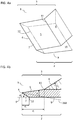
- Fig. 3a is a perspective view of a cutting blade according to the present invention.
- This cutting blade 1 has a blade body 15 which comprises a first face 2 and a second face which is opposed to the first face 2.
- the first face 2 comprises a first surface 9 and a primary bevel 7 while the second surface 3 comprises a secondary bevel 5 and an upper surface 8 being parallel to the first surface 9.
- a cutting edge 4 is located at the intersection of the primary bevel 7 and the secondary bevel 5 .
- the cutting edge 4 is shaped straightly or substantially straightly.
- the secondary bevel 5 is connected to the upper surface 8 via an intersecting line 11 and the primary bevel 5 is connected to the first surface 9 via an intersecting line 12.
- FIG. 3b a cross-sectional view of the cutting blade of Fig. 3a is shown.
- This cutting blade 1 comprises a first face 2 and a second face 3 which is opposed to the first face 2.
- the first face 2 comprises a plane first surface 9 and a primary bevel 7 with a first wedge angle ⁇ 1 between the first surface 9 and the primary bevel 7.
- the second face 3 comprises a secondary bevel 5 with a second wedge angle ⁇ 2 between the first surface 9 and the secondary bevel 5 which is smaller than ⁇ 1 .
- the second face 3 comprises an upper surface 8. At the intersection of the primary bevel 7 and the secondary bevel 5 a cutting edge 4 is located.
- the secondary bevel 5 is connected to the upper surface 8 via an intersecting line 11 and the primary bevel 5 is connected to the first surface 9 via an intersecting line 12.
- the primary bevel 7 has a length d 1 being the dimension projected onto the first surface 9 which is in the range from 0.5 to 5 ⁇ m.
- the secondary bevel 6 has a length d 2 being the dimension projected onto the first surface 9 which is in the range from 5 to 75 ⁇ m, preferably 15 to 35 ⁇ m.
- Fig.4a is a perspective view of the cutting blade according to the present invention.
- This cutting blade 1 has a blade body 15 which comprises a first face 2 and a second face 3 which is opposed to the first face 2.
- the first face 2 comprises a first surface 9 and a primary bevel 7 while the second surface 3 comprises a secondary bevel 5 and a tertiary bevel 6.
- the primary bevel 7 is connected via a first intersecting line 12 with the first face 9 and the secondary bevel 5 is connected via a second intersecting line 11 with the tertiary bevel 6.
- a cutting edge 4 is located at the intersection of the primary bevel 7 and the secondary bevel 5 .
- the cutting edge 4 is shaped linearly.
- FIG. 4b a cross-sectional view of the cutting blade of Fig. 4a is shown.
- This cutting blade 1 comprises a first face 2 and a second face 3 which is opposed to the first face 2.
- the first face 2 comprises a plane first surface 9 and a primary bevel 7 with a first wedge angle ⁇ 1 between the first surface 9 and the primary bevel 5.
- the second face 3 comprises a secondary bevel 5 with a second wedge angle ⁇ 2 between the first surface 9 and the secondary bevel 6 which is smaller than ⁇ 1 .
- the tertiary bevel 6 has a third wedge angle ⁇ 3 which is larger than ⁇ 2 .
- a cutting edge 4 is located at the intersection of the primary bevel 7 and the secondary bevel 5 a cutting edge 4 is located.
- the primary bevel 7 has a length d 1 being the dimension projected onto the first surface 9 which is in the range from 0.5 to 5 ⁇ m.
- the secondary bevel 5 has a length d 2 being the dimension projected onto the first surface 9 which is in the range from 5 to 75 ⁇ m, preferably 15 to 35 ⁇ m.
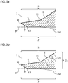
- FIG. 5a a further sectional view of a cutting blade of the present invention is shown where the blade body 15 is monolithic.
- the cutting blade 1 comprises a first face 2 and a second face 3 which is opposed to the first face 2.
- the first face 2 comprises a plane first surface 9 and a primary bevel 7 while the second surface 3 comprises a secondary bevel 5 and a tertiary bevel 6.
- the primary bevel 7 is connected via a first intersecting line 12 with the first face 9 and the secondary bevel 5 is connected via a second intersecting line 11 with the tertiary bevel 6.
- the cutting edge 4 is located at the intersection of the primary bevel 7 and the secondary bevel 5 .
- a further sectional view of a cutting blade of the present invention is shown wherein the blade body 15 comprises a first material 18, e.g. silicon, with a second material 19, e.g. a diamond layer on the first material 18 at the first face 2.
- the primary bevel 7 and the secondary bevel 5 are located in the second material 19 while the tertiary bevel 6 is located in the first material 18.
- the first material 18 and the second material 19 are joined along a boundary surface 20.
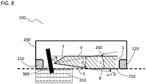
- a shaving device 100 of the present invention is shown illustrating the cutting process for a hair 300 which protrudes from the skin 310.
- the shaving device 100 comprises a housing 200 with a forward skin support 210 and a rearward skin support 220. Between both supports 210, 220 a blade 1 is arranged.
- the shaving device 100 with the skin contacting surface 250 is brought in contact with the skin 310.
- the hair 300 which is protruding from the skin 310 is touched by the cutting edge of the cutting blade 1.
- the cutting blade 1 has a first face 2 and a second face 3. According to this embodiment, the first face 2 is the clearance face.
- the first face 2 comprises a plane first surface 9 and a primary bevel 7 while the second surface 3 comprises a secondary bevel 6 and a surface 8 which is parallel to the first surface 9.
- the clearance angle ⁇ between the primary bevel 7 and the skin contacting surface 250 is larger than 0° but smaller or equal 11° which results in a high skin safety.
- a larger effective cutting angle ⁇ between the skin contacting surface 250 and the bisecting line 260 of the first wedge angle ⁇ 1 may be realized, i.e. ⁇ ⁇ 10°, which improves the efficiency of the hairs being cut.
- a shaving device 100 of the present invention is shown illustrating the cutting process for a hair 300 which protrudes from the skin 310.
- the shaving device 100 comprises a housing 200 with a forward skin support 210 and a rearward skin support 220. Between both supports 210, 220 a blade 1 is arranged.
- the shaving device 100 with the skin contacting surface 250 is brought in contact with the skin 310 and the hair 300 which protrudes from the skin 310 is touched by the cutting edge of the cutting blade 1.
- the second face 3 is the clearance face.
- the clearance angle ⁇ between the secondary bevel 5 and the skin contacting surface 250 is larger than 0° but smaller or equal 11° which results in a high skin safety.
- a larger effective cutting angle ⁇ between the skin contacting surface 250 and the bisecting line 260 of the first wedge angle ⁇ 1 may be realized, i.e. ⁇ ⁇ 10°, which improves the efficiency of the hairs being cut.
- a shaving device 100 of the present invention is shown illustrating the cutting process for a hair 300 which protrudes from the skin 310.
- the shaving device 100 comprises a housing 200 with a forward skin support 210 and a rearward skin support 220. Between both supports 210, 220 a blade 1 is arranged.
- the shaving device 100 with the skin contacting surface 250 is brought in contact with the skin 310 and the hair 300 which is sticking out of the skin 310 is touched by the cutting edge 4 of the cutting blade 1.
- the first face 2 is the clearance face.
- the clearance angle ⁇ between the primary bevel 7 and the skin contacting surface 250 is 0° which results in a high skin safety.
- a larger effective cutting angle ⁇ between the skin contacting surface 250 and the bisecting line 260 of the first wedge angle ⁇ 1 may be realized, i.e. ⁇ ⁇ 10°, which improves the efficiency of the hair cutting,.
- a shaving device 100 of the present invention is shown illustrating the cutting process for a hair 300 which sticks out of the skin 310.
- the shaving device 100 comprises a housing 200 with a forward skin support 210 and a rearward skin support 220. Between both supports 210, 220 a blade 1 is arranged.
- the shaving device 100 with the skin contacting surface 250 is brought in contact with the skin 310 and the hair 300 which is sticking out of the skin 310 is touched by the cutting edge 4 of the cutting blade 1.
- the second face 2 is the clearance face.
- the clearance angle ⁇ between the second face 2 with the secondary bevel 5 of the cutting blade 1 and the skin contacting surface 250 is 0° which improves the skin safety.
- a shaving device 100 of the present invention is shown illustrating the cutting process for a hair 300 which sticks out of the skin 310.
- the shaving device 100 comprises a housing 200 with a forward skin support 210 and a rearward skin support 220. Between both supports 210, 220 a blade 1 is arranged.
- the shaving device 100 with the skin contacting surface 250 is brought in contact with the skin 310 and the hair 300 which is sticking out of the skin 310 is touched by the cutting edge 4 of the cutting blade 1.
- the second face 2 is the clearance face.
- the clearance angle ⁇ between the second face 2 with the secondary bevel 5 of the cutting blade 1 and the skin contacting surface 250 is smaller than 0° which improves the skin safety.
- a flow chart of the inventive process is shown.
- a silicon wafer 101 is coated by PE-CVD or thermal treatment (low pressure CVD) with a silicon nitride (Si 3 N 4 ) layer 102 as protection layer for the silicon.
- the layer thickness and deposition procedure must be chosen carefully to enable sufficient chemical stability to withstand the following etching steps.
- a photoresist 103 is deposited onto the Si 3 N 4 coated substrate and subsequently patterned by photolithography.
- the (Si 3 N 4 ) layer is then structured by e.g. CF 4 -plasma reactive ion etching (RIE) using the patterned photoresist as mask.
- RIE reactive ion etching
- the photoresist 103 is stripped by organic solvents in step 3.
- the remaining, patterned Si 3 N 4 layer 102 serves as a mask for the following pre-structuring step 4 of the silicon wafer 101 e.g. by anisotropic wet chemical etching in KOH.
- the etching process is ended when the structures on the second face 3 have reached a predetermined depth and a continuous silicon first face 2 remains.
- Other wet- and dry chemical processes may be suited, e.g. isotropic wet chemical etching in HF/HNO 3 solutions or the application of fluorine containing plasmas.
- the remaining Si 3 N 4 is removed by, e.g. hydrofluoric acid (HF) or fluorine plasma treatment.
- HF hydrofluoric acid
- the pre-structured Si-substrate is coated with an approx. 10 ⁇ m thin diamond layer 104, e.g. nano-crystalline diamond.
- the diamond layer 104 can be deposited onto the pre-structured second surface 3 and the continuous first surface 2 of the Si-wafer 101 (as shown in step 6) or only on the continuous fist surface 2 of the Si-wafer (not shown here).
- the diamond layer 104 on the structured second surface 3 has to be removed in a further step 7 prior to the following edge formation steps 9-11 of the cutting blade.
- the selective removal of the diamond layer 104 is performed e.g. by using an Ar/O 2 -plasma (e.g.
- step 8 the silicon wafer 101 is thinned so that the diamond layer 104 is partially free standing without substrate material and the desired substrate thickness is achieved in the remaining regions.
- This step can be performed by wet chemical etching in KOH or HF/HNO 3 etchants or preferably by plasma etching in CF 4 , SF 6 , or CHF 3 containing plasmas in RIE or ICP mode.
- step 9 the diamond film is etched anisotropically by an Ar/O 2 -plasma in an RIE system to form an almost vertical bevel 5' with a 90° corner in the diamond layer 104, which is required to form primary bevel 7 on the first face 2 of the cutting blade as shown in step 10.
- the Si-wafer 101 is now turned to expose the first face 2 to the subsequent etching step 10 ( Fig. 9b ).
- the 90° corner 5' is chamfered to form primary bevel 7.
- Process details are disclosed for instance in EP 2 727 880 .
- step 11 the cutting edge formation is completed by processing the Si-wafer 101 on the second face 3 to form secondary bevel 5 as shown in Fig. 9d .
- Multiple bevels may be formed by varying the process parameters. Process details are disclosed for instance in DE 198 59 905 A1 .
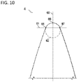
- Fig. 10 it is shown how the tip radius can be determined.
- the tip radius is determined by first drawing a line 60 bisecting the cross-sectional image of the first bevel of the cutting edge 1 in half. Where line 60 bisects the first bevel point 65 is drawn. A second line 61 is drawn perpendicular to line 60 at a distance of 110 nm from point 65. Where line 61 bisects the first bevel two additional points 66 and 67 are drawn. A circle 62 is then constructed from points 65, 66 and 67. The radius of circle 62 is the tip radius for coated blade 1.
Landscapes
- Life Sciences & Earth Sciences (AREA)
- Forests & Forestry (AREA)
- Engineering & Computer Science (AREA)
- Mechanical Engineering (AREA)
- Physics & Mathematics (AREA)
- Geometry (AREA)
- Dry Shavers And Clippers (AREA)
- Electrical Discharge Machining, Electrochemical Machining, And Combined Machining (AREA)
- Glass Compositions (AREA)
- Formation And Processing Of Food Products (AREA)
- Knives (AREA)
- Cosmetics (AREA)
Priority Applications (11)
| Application Number | Priority Date | Filing Date | Title |
|---|---|---|---|
| EP20169937.8A EP3895861A1 (de) | 2020-04-16 | 2020-04-16 | Rasiervorrichtung |
| PCT/EP2021/059174 WO2021209308A1 (en) | 2020-04-16 | 2021-04-08 | Shaving device |
| CA3177494A CA3177494A1 (en) | 2020-04-16 | 2021-04-08 | Shaving device |
| CN202180028506.1A CN115715249A (zh) | 2020-04-16 | 2021-04-08 | 剃刮装置 |
| DE112021002343.8T DE112021002343T5 (de) | 2020-04-16 | 2021-04-08 | Rasiervorrichtung |
| EP21717845.8A EP4135945B1 (de) | 2020-04-16 | 2021-04-08 | Rasiervorrichtung |
| JP2022560860A JP7513744B2 (ja) | 2020-04-16 | 2021-04-08 | 剃毛装置 |
| GB2215321.7A GB2608946A (en) | 2020-04-16 | 2021-04-08 | Shaving device |
| BR112022020954A BR112022020954A2 (pt) | 2020-04-16 | 2021-04-08 | Dispositivo de barbeamento ou depilação |
| AU2021255781A AU2021255781A1 (en) | 2020-04-16 | 2021-04-08 | Shaving device |
| US17/966,357 US20230037149A1 (en) | 2020-04-16 | 2022-10-14 | Shaving device |
Applications Claiming Priority (1)
| Application Number | Priority Date | Filing Date | Title |
|---|---|---|---|
| EP20169937.8A EP3895861A1 (de) | 2020-04-16 | 2020-04-16 | Rasiervorrichtung |
Publications (1)
| Publication Number | Publication Date |
|---|---|
| EP3895861A1 true EP3895861A1 (de) | 2021-10-20 |
Family
ID=70292925
Family Applications (2)
| Application Number | Title | Priority Date | Filing Date |
|---|---|---|---|
| EP20169937.8A Withdrawn EP3895861A1 (de) | 2020-04-16 | 2020-04-16 | Rasiervorrichtung |
| EP21717845.8A Active EP4135945B1 (de) | 2020-04-16 | 2021-04-08 | Rasiervorrichtung |
Family Applications After (1)
| Application Number | Title | Priority Date | Filing Date |
|---|---|---|---|
| EP21717845.8A Active EP4135945B1 (de) | 2020-04-16 | 2021-04-08 | Rasiervorrichtung |
Country Status (10)
| Country | Link |
|---|---|
| US (1) | US20230037149A1 (de) |
| EP (2) | EP3895861A1 (de) |
| JP (1) | JP7513744B2 (de) |
| CN (1) | CN115715249A (de) |
| AU (1) | AU2021255781A1 (de) |
| BR (1) | BR112022020954A2 (de) |
| CA (1) | CA3177494A1 (de) |
| DE (1) | DE112021002343T5 (de) |
| GB (1) | GB2608946A (de) |
| WO (1) | WO2021209308A1 (de) |
Cited By (2)
| Publication number | Priority date | Publication date | Assignee | Title |
|---|---|---|---|---|
| EP4292782A1 (de) * | 2022-06-17 | 2023-12-20 | Dorco Co., Ltd. | Rasierklingeneinheit |
| EP4292783A1 (de) * | 2022-06-17 | 2023-12-20 | Dorco Co., Ltd. | Razor cartridge |
Families Citing this family (3)
| Publication number | Priority date | Publication date | Assignee | Title |
|---|---|---|---|---|
| AU2021254781A1 (en) | 2020-04-16 | 2022-09-22 | The Gillette Company Llc | Multi-layer coatings for a razor blade |
| AU2021255959A1 (en) | 2020-04-16 | 2022-09-22 | The Gillette Company Llc | Razor blade |
| US20210323180A1 (en) * | 2020-04-16 | 2021-10-21 | The Gillette Company Llc | Razor cartridge |
Citations (10)
| Publication number | Priority date | Publication date | Assignee | Title |
|---|---|---|---|---|
| BE472676A (de) * | 1947-04-19 | 1947-05-31 | ||
| US3606682A (en) * | 1967-10-30 | 1971-09-21 | Corning Glass Works | Razor blades |
| US3842499A (en) | 1972-09-08 | 1974-10-22 | Gillette Co | Razor blade assembly |
| US3863340A (en) | 1972-09-08 | 1975-02-04 | Gillette Co | Plural edge shaving system |
| DE19859905A1 (de) | 1998-01-27 | 1999-09-09 | Gluche | Diamantschneidwerkzeug |
| WO2000064644A1 (en) * | 1999-04-23 | 2000-11-02 | The Gillette Company | Safety razor |
| WO2002100610A1 (en) * | 2001-06-12 | 2002-12-19 | Element Six Limited | Cvd diamond cutting insert |
| US6655030B2 (en) | 2000-12-22 | 2003-12-02 | Koninklijke Philips Electronics N.V. | Shaving head and shaver provided with such a shaving head |
| US20120311865A1 (en) * | 2011-06-08 | 2012-12-13 | Zafirro, Llc | Mineral blade and razor for use with same |
| EP2727880A1 (de) | 2012-11-05 | 2014-05-07 | GFD Gesellschaft für Diamantprodukte mbH | Dreidimensionales, mikromechanisches Bauteil mit einer Fase und Verfahren zu dessen Herstellung |
Family Cites Families (7)
| Publication number | Priority date | Publication date | Assignee | Title |
|---|---|---|---|---|
| US2244053A (en) * | 1935-06-22 | 1941-06-03 | Gregory J Comstock | Hard cemented carbide composite |
| US5795648A (en) * | 1995-10-03 | 1998-08-18 | Advanced Refractory Technologies, Inc. | Method for preserving precision edges using diamond-like nanocomposite film coatings |
| JP3641794B2 (ja) | 1999-07-14 | 2005-04-27 | きみ子 末田 | ダイヤモンド入り刃材 |
| GB0212530D0 (en) | 2002-05-30 | 2002-07-10 | Diamanx Products Ltd | Diamond cutting insert |
| EP1608492A1 (de) | 2003-04-03 | 2005-12-28 | Eveready Battery Company, Inc. | Rasierklingen mit nichtlinearer schneide und herstellungsverfahren dafür |
| MX2014004037A (es) | 2011-10-06 | 2014-05-30 | Bic Violex Sa | Cuchilla para rasurar, cabeza para rasurar y metodos de manufactura. |
| US9808944B2 (en) | 2014-06-17 | 2017-11-07 | The Gillette Company Llc | Methods of manufacturing silicon blades for shaving razors |
-
2020
- 2020-04-16 EP EP20169937.8A patent/EP3895861A1/de not_active Withdrawn
-
2021
- 2021-04-08 JP JP2022560860A patent/JP7513744B2/ja active Active
- 2021-04-08 CA CA3177494A patent/CA3177494A1/en active Pending
- 2021-04-08 CN CN202180028506.1A patent/CN115715249A/zh active Pending
- 2021-04-08 WO PCT/EP2021/059174 patent/WO2021209308A1/en active Application Filing
- 2021-04-08 DE DE112021002343.8T patent/DE112021002343T5/de active Pending
- 2021-04-08 AU AU2021255781A patent/AU2021255781A1/en active Pending
- 2021-04-08 EP EP21717845.8A patent/EP4135945B1/de active Active
- 2021-04-08 BR BR112022020954A patent/BR112022020954A2/pt unknown
- 2021-04-08 GB GB2215321.7A patent/GB2608946A/en active Pending
-
2022
- 2022-10-14 US US17/966,357 patent/US20230037149A1/en active Pending
Patent Citations (10)
| Publication number | Priority date | Publication date | Assignee | Title |
|---|---|---|---|---|
| BE472676A (de) * | 1947-04-19 | 1947-05-31 | ||
| US3606682A (en) * | 1967-10-30 | 1971-09-21 | Corning Glass Works | Razor blades |
| US3842499A (en) | 1972-09-08 | 1974-10-22 | Gillette Co | Razor blade assembly |
| US3863340A (en) | 1972-09-08 | 1975-02-04 | Gillette Co | Plural edge shaving system |
| DE19859905A1 (de) | 1998-01-27 | 1999-09-09 | Gluche | Diamantschneidwerkzeug |
| WO2000064644A1 (en) * | 1999-04-23 | 2000-11-02 | The Gillette Company | Safety razor |
| US6655030B2 (en) | 2000-12-22 | 2003-12-02 | Koninklijke Philips Electronics N.V. | Shaving head and shaver provided with such a shaving head |
| WO2002100610A1 (en) * | 2001-06-12 | 2002-12-19 | Element Six Limited | Cvd diamond cutting insert |
| US20120311865A1 (en) * | 2011-06-08 | 2012-12-13 | Zafirro, Llc | Mineral blade and razor for use with same |
| EP2727880A1 (de) | 2012-11-05 | 2014-05-07 | GFD Gesellschaft für Diamantprodukte mbH | Dreidimensionales, mikromechanisches Bauteil mit einer Fase und Verfahren zu dessen Herstellung |
Non-Patent Citations (4)
| Title |
|---|
| MARKUS MOHR ET AL.: "Youngs modulus, fracture strength, and Poisson's ratio of nanocrystalline diamond films", J. APPL. PHYS., vol. 116, 2014, pages 124308, XP012190286, DOI: 10.1063/1.4896729 |
| R. DANZERJ. KRIEGESMANN ET AL.: "Technische keramische Werkstoffe", HVB PRESS, article "Der 4-Kugelversuch zur Ermittlung der biaxialen Biegefestig-keit sproder Werkstoffe" |
| R.MORRELL ET AL., INT. JOURNAL OF REFRACTORY METALS & HARD MATERIALS, vol. 28, 2010, pages 508 - 515 |
| YEON-GIL JUNG, J. MATER. RES., vol. 19, no. 10, pages 3076 |
Cited By (2)
| Publication number | Priority date | Publication date | Assignee | Title |
|---|---|---|---|---|
| EP4292782A1 (de) * | 2022-06-17 | 2023-12-20 | Dorco Co., Ltd. | Rasierklingeneinheit |
| EP4292783A1 (de) * | 2022-06-17 | 2023-12-20 | Dorco Co., Ltd. | Razor cartridge |
Also Published As
| Publication number | Publication date |
|---|---|
| JP2023522158A (ja) | 2023-05-29 |
| EP4135945A1 (de) | 2023-02-22 |
| EP4135945B1 (de) | 2024-02-21 |
| DE112021002343T5 (de) | 2023-01-26 |
| BR112022020954A2 (pt) | 2022-12-06 |
| CA3177494A1 (en) | 2021-10-21 |
| GB2608946A (en) | 2023-01-18 |
| JP7513744B2 (ja) | 2024-07-09 |
| CN115715249A (zh) | 2023-02-24 |
| GB202215321D0 (en) | 2022-11-30 |
| WO2021209308A1 (en) | 2021-10-21 |
| US20230037149A1 (en) | 2023-02-02 |
| AU2021255781A1 (en) | 2022-11-03 |
Similar Documents
| Publication | Publication Date | Title |
|---|---|---|
| EP3895861A1 (de) | Rasiervorrichtung | |
| EP4135948B1 (de) | Schneidklinge und haarentfernungsvorrichtung | |
| EP4135947B1 (de) | Schneidklinge und haarentfernungsvorrichtung | |
| EP4135949B1 (de) | Schneidmesser mit konkaver fase und haarentfernungsvorrichtung | |
| US20240131740A1 (en) | Shaving device | |
| US20240042637A1 (en) | Cutting element and hair removal device | |
| US20240042636A1 (en) | Cutting element with asymmetric cutting segments | |
| US20240042635A1 (en) | Cutting element and hair removal device |
Legal Events
| Date | Code | Title | Description |
|---|---|---|---|
| PUAI | Public reference made under article 153(3) epc to a published international application that has entered the european phase |
Free format text: ORIGINAL CODE: 0009012 |
|
| STAA | Information on the status of an ep patent application or granted ep patent |
Free format text: STATUS: THE APPLICATION HAS BEEN PUBLISHED |
|
| AK | Designated contracting states |
Kind code of ref document: A1 Designated state(s): AL AT BE BG CH CY CZ DE DK EE ES FI FR GB GR HR HU IE IS IT LI LT LU LV MC MK MT NL NO PL PT RO RS SE SI SK SM TR |
|
| B565 | Issuance of search results under rule 164(2) epc |
Effective date: 20200918 |
|
| STAA | Information on the status of an ep patent application or granted ep patent |
Free format text: STATUS: THE APPLICATION IS DEEMED TO BE WITHDRAWN |
|
| 18D | Application deemed to be withdrawn |
Effective date: 20220421 |
|
| P01 | Opt-out of the competence of the unified patent court (upc) registered |
Effective date: 20230430 |