EP4292782A1 - Rasierklingeneinheit - Google Patents
Rasierklingeneinheit Download PDFInfo
- Publication number
- EP4292782A1 EP4292782A1 EP23179729.1A EP23179729A EP4292782A1 EP 4292782 A1 EP4292782 A1 EP 4292782A1 EP 23179729 A EP23179729 A EP 23179729A EP 4292782 A1 EP4292782 A1 EP 4292782A1
- Authority
- EP
- European Patent Office
- Prior art keywords
- facet
- blade
- tip
- degrees
- angle
- Prior art date
- Legal status (The legal status is an assumption and is not a legal conclusion. Google has not performed a legal analysis and makes no representation as to the accuracy of the status listed.)
- Pending
Links
- 238000005520 cutting process Methods 0.000 claims abstract description 57
- 239000000758 substrate Substances 0.000 claims abstract description 56
- 239000011247 coating layer Substances 0.000 claims abstract description 22
- 239000000463 material Substances 0.000 description 10
- 230000008859 change Effects 0.000 description 8
- 230000001050 lubricating effect Effects 0.000 description 7
- 230000008878 coupling Effects 0.000 description 6
- 238000010168 coupling process Methods 0.000 description 6
- 238000005859 coupling reaction Methods 0.000 description 6
- 239000010410 layer Substances 0.000 description 5
- 238000000034 method Methods 0.000 description 3
- 230000009467 reduction Effects 0.000 description 3
- 239000011347 resin Substances 0.000 description 3
- 229920005989 resin Polymers 0.000 description 3
- 230000035807 sensation Effects 0.000 description 3
- IJGRMHOSHXDMSA-UHFFFAOYSA-N Atomic nitrogen Chemical compound N#N IJGRMHOSHXDMSA-UHFFFAOYSA-N 0.000 description 2
- 206010040880 Skin irritation Diseases 0.000 description 2
- 239000011248 coating agent Substances 0.000 description 2
- 238000000576 coating method Methods 0.000 description 2
- 230000000694 effects Effects 0.000 description 2
- 230000007794 irritation Effects 0.000 description 2
- 238000004519 manufacturing process Methods 0.000 description 2
- 239000002184 metal Substances 0.000 description 2
- 238000000926 separation method Methods 0.000 description 2
- 229910052710 silicon Inorganic materials 0.000 description 2
- 239000010703 silicon Substances 0.000 description 2
- 230000036556 skin irritation Effects 0.000 description 2
- 231100000475 skin irritation Toxicity 0.000 description 2
- ZOXJGFHDIHLPTG-UHFFFAOYSA-N Boron Chemical compound [B] ZOXJGFHDIHLPTG-UHFFFAOYSA-N 0.000 description 1
- OKTJSMMVPCPJKN-UHFFFAOYSA-N Carbon Chemical compound [C] OKTJSMMVPCPJKN-UHFFFAOYSA-N 0.000 description 1
- 238000005452 bending Methods 0.000 description 1
- 230000015572 biosynthetic process Effects 0.000 description 1
- 229910052796 boron Inorganic materials 0.000 description 1
- 229910052799 carbon Inorganic materials 0.000 description 1
- 239000000919 ceramic Substances 0.000 description 1
- 230000007423 decrease Effects 0.000 description 1
- 238000010586 diagram Methods 0.000 description 1
- 230000001815 facial effect Effects 0.000 description 1
- 230000006870 function Effects 0.000 description 1
- 230000003993 interaction Effects 0.000 description 1
- 230000007246 mechanism Effects 0.000 description 1
- 230000004048 modification Effects 0.000 description 1
- 238000012986 modification Methods 0.000 description 1
- 229910052757 nitrogen Inorganic materials 0.000 description 1
- 230000000704 physical effect Effects 0.000 description 1
- 238000003825 pressing Methods 0.000 description 1
- 239000000047 product Substances 0.000 description 1
- 229910001220 stainless steel Inorganic materials 0.000 description 1
- 239000010935 stainless steel Substances 0.000 description 1
- 239000013589 supplement Substances 0.000 description 1
- 238000003466 welding Methods 0.000 description 1
Images


Classifications
-
- B—PERFORMING OPERATIONS; TRANSPORTING
- B26—HAND CUTTING TOOLS; CUTTING; SEVERING
- B26B—HAND-HELD CUTTING TOOLS NOT OTHERWISE PROVIDED FOR
- B26B21/00—Razors of the open or knife type; Safety razors or other shaving implements of the planing type; Hair-trimming devices involving a razor-blade; Equipment therefor
- B26B21/54—Razor-blades
- B26B21/56—Razor-blades characterised by the shape
- B26B21/565—Bent razor blades; Razor blades with bent carriers
-
- B—PERFORMING OPERATIONS; TRANSPORTING
- B26—HAND CUTTING TOOLS; CUTTING; SEVERING
- B26B—HAND-HELD CUTTING TOOLS NOT OTHERWISE PROVIDED FOR
- B26B21/00—Razors of the open or knife type; Safety razors or other shaving implements of the planing type; Hair-trimming devices involving a razor-blade; Equipment therefor
- B26B21/54—Razor-blades
- B26B21/56—Razor-blades characterised by the shape
-
- B—PERFORMING OPERATIONS; TRANSPORTING
- B26—HAND CUTTING TOOLS; CUTTING; SEVERING
- B26B—HAND-HELD CUTTING TOOLS NOT OTHERWISE PROVIDED FOR
- B26B21/00—Razors of the open or knife type; Safety razors or other shaving implements of the planing type; Hair-trimming devices involving a razor-blade; Equipment therefor
- B26B21/40—Details or accessories
- B26B21/4012—Housing details, e.g. for cartridges
- B26B21/4031—Housing details, e.g. for cartridges characterised by special geometric shaving parameters, e.g. blade span or exposure
-
- B—PERFORMING OPERATIONS; TRANSPORTING
- B26—HAND CUTTING TOOLS; CUTTING; SEVERING
- B26B—HAND-HELD CUTTING TOOLS NOT OTHERWISE PROVIDED FOR
- B26B21/00—Razors of the open or knife type; Safety razors or other shaving implements of the planing type; Hair-trimming devices involving a razor-blade; Equipment therefor
- B26B21/54—Razor-blades
- B26B21/58—Razor-blades characterised by the material
- B26B21/60—Razor-blades characterised by the material by the coating material
Definitions
- the present disclosure relates to a razor cartridge, and more particularly, to a razor cartridge used in a disposable razor or a cartridge replaceable razor.
- a razor is a product generally used to cut and remove hair, such as facial hair, body hair, and beards.
- the razor consists of a handle to be gripped by a user, and a razor cartridge having a razor blade that come into contact with a skin surface to perform the act of shaving according to movement of the user's holding the handle.
- a razor includes a disposable razor in which the razor cartridge is not replaceable, and a cartridge replaceable razor in which a razor cartridge is selectively exchangeable by the user.
- the razor cartridge includes at least one blade disposed transversely to a shaving direction to cut body hair and a blade housing for accommodating the blade in a longitudinal direction.
- a cutting edge for substantially cutting hair is formed at a tip of a blade, and the cutting edge is exposed upward of the blade housing.
- the cutting force generally refers to a cutting resistance between the body hair and the blade during hair cutting. The smaller the cutting force is, the more efficiently the body hair is cut and the more comfortable the user feels during shaving.
- the blade includes a substrate used as a base material, a metal coating layer and a resin coating layer staked on the substrate, and the cutting force of the blade is based on the shape constituting the blade. For example, if the thickness of the substrate is thinner, the cutting force of the blade is further reduced, thereby enabling efficient cutting of the body hair and providing the user with a comfortable shaving sensation. Also, in another example, the cutting force of the blade depends on the cross-sectional shape of the blade that constitutes one side facing the skin surface and the other side opposite.
- a metal coating layer and a resin coating layer staked from both sides of the substrate are formed in a symmetrical shape of the same thickness.
- Such a conventional blade having a symmetrical shape has a limitation in improving the cutting force and durability of the blade due to the characteristics of one side facing the skin surface to cut body hair and the opposite side facing away from the skin surface.
- An aspect of the present disclosure provides a razor cartridge with a blade improved in shape so as to have an asymmetrical shape in which a thicknesses from one side facing skin surface and the other opposite side differs based on a center line of a cross section of the blade.
- a razor cartridge including: at least one blade having an edge portion and a cutting edge formed at a tip of the edge portion; and a blade housing for receiving the at least one blade in a longitudinal direction so that at least a portion of the cutting edge is exposed through a top of the blade housing.
- the at least one blade includes: a substrate comprising a substrate tip, a first surface extending toward one side from the substrate tip, and a second surface extending toward the other side from the substrate tip; and a coating layer formed on the substrate to form the cutting edge, and comprising a first facet extending toward one side from a final edge forming a tip of the cutting edge, to face a skin surface during shaving and a second facet extending toward the other side from the final edge to opposite to the first facet.
- a blade angle between the skin surface and a line passing through a bisector of the edge portion is greater than an efficient angle between the skin surface and a line passing through a bisector of the final tip.
- the efficient angle may be less than 10 degrees.
- the blade angle may be 22 degrees or less.
- the blade angle may be 17 degrees or less.
- the final tip may be spaced apart from the skin surface during shaving.
- the first facet may be formed within 1 micrometer of the final tip.
- the second facet may be formed within 50 micrometers from the final tip.
- An angle between the first facet and the second facet may have a value between 50 degrees and 75 degrees.
- the blade may further include a third facet extending from the first facet, and an angle between the first facet and the third facet may have a value between 120 degrees and 165 degrees.
- the blade may further include a third facet extending from the first facet, and an angle between an extension line of the second facet and an extension line of the third facet may have a value between 25 degrees and 50 degrees.
- the blade may further include a third facet extending from the first facet, and the third facet may be formed within 50 micrometers from the final tip.
- the blade may further include a third facet extending from the first facet and a fifth facet extending from the third facet.
- a point where the third facet and the fifth facet cross each other may be defined as a first intersection point.
- a point where a parallel line to the skin surface and passing through the first intersection point and a line passing through the bisector of the final tip cross each other may be defined as a second intersection point.
- a distance between the first intersection point and the second intersection point may have a value between 1 micrometer and 5 micrometers.
- a distance between the second intersection point and the final tip may have a value between 2 micrometers and 7 micrometers.
- a razor cartridge including at least one blade having an edge portion and a cutting edge formed at a tip of the edge portion; and a blade housing for receiving the at least one blade in a longitudinal direction so that at least a portion of the cutting edge is exposed through a top of the blade housing.
- the at least one blade includes: a substrate comprising a substrate tip, a first surface extending toward one side from the substrate tip, and a second surface extending toward the other side from the substrate tip; and a coating layer formed on the substrate to form the cutting edge, and comprising a first facet extending toward one side from a final edge forming a tip of the cutting edge, to face a skin surface during shaving and a second facet extending toward the other side from the final edge to opposite to the first facet.
- An efficient angle between the skin surface and a line passing through a bisector of the final tip is less than 10 degrees.
- the blade angle between the skin surface and the line passing through the bisector of the edge portion is greater than the efficient angle between the skin surface and the line passing through the bisector of the final tip, so that a cutting force can be reduced according to shaving characteristics and irritation to the skin surface can be minimized.
- the razor cartridge according to an embodiment of the present disclosure may be inseparably coupled to or integrally formed with a handle of a disposable razor, and may be selectively coupled to a handle of a cartridge replaceable razor.
- FIG. 1 is a schematic side view of a razor 10
- FIG. 2 is a plan view of a razor cartridge 500 according to an embodiment of the present disclosure shown in FIG. 1
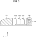
- FIG. 3 is a cross-sectional view taken along line III-III shown in FIG. 2
- FIG. 4 is a view showing a configuration of a blade 1000 shown in FIG. 3
- FIG. 5 is an enlarged cross-sectional view of area A shown in FIG. 4 .
- the razor 10 includes a handle 100, a handle coupling part 300, and a razor cartridge 500 according to an embodiment of the present disclosure.
- the handle 100 is gripped by a user.
- the handle 100 includes a handle body 110 and a handle header 130.
- the handle body 110 is a part of razor 10 gripped by the user.
- the handle header 130 may be provided at one end of the handle body 110 and detachably coupled to the razor cartridge 500.
- the handle body 110 pivotably supports the selectively coupled razor cartridge 500.
- the handle body 110 is inseparably coupled to or integrally formed with the razor cartridge 500.
- the handle header 130 is coupled to the handle coupling part 300 formed under the razor cartridge 500.
- the handle header 130 is coupled to the handle coupling part 300 so as to pivotably support the razor cartridge 500 within a certain angle range for a fixed axis or an axis that moves within a certain range.
- the handle header 130 is selectively coupled to the handle coupling part 300 in the cartridge replaceable razor.
- the handle 100 may be provided with an operator (not shown) capable of operating the handle header 130. The user is able to release the coupling between the handle header 130 and the handle coupling part 300 by operating the operator.
- the razor cartridge 500 includes a blade housing 510, a lubricating band 530, a clip 550, and a blade 1000.
- the blade housing 510 includes a frame 511, a guard 513, and a cap 515.
- the guard 513 is disposed in front (or in a positive X-axis direction of) the frame 511
- the cap 515 is disposed at rear (or in a negative X-axis direction) of the frame 511.
- a central portion of the frame 511 is formed to be open upward.
- the frame 511 accommodates at least one blade 1000 in a longitudinal direction (Y-axis direction).
- each blade 1000 may be arranged in a row in a transverse direction (X-axis direction) to the other blades 1000.
- the guard 513 comes into close contact with the user's skin surface S (see FIGS. 6 and 9 ) to pull the skin surface, thereby improving the shaving effect of the blade 1000.
- An embossed or intaglio pattern may be formed in an upper surface of the guard 513 so as to more effectively pull the user's skin surface S.
- the upper surface of the guard 513 may be formed of a material such as rubber and silicon.
- the guard 513 serves to pre-apply supplements for shaving to the skin before the body hair touches the blade 1000.
- the lubricating band 530 exposed through a top of the razor cartridge 500 may be disposed at the cap 515.
- the lubricating band 530 includes a lubricating material, and allows the lubricating material to be applied to the skin surface S where the blade 1000 passes during shaving.
- the lubricating material may include components for protecting the skin surface S after shaving.
- the clip 550 surrounds both sides of the frame 511 and is coupled to the blade housing 510.
- the clip 550 prevents separation of the blade 1000 from the blade housing 510.
- the blade 1000 includes a base portion 1100, a bent portion 1200, and an edge portion 1300, as shown in FIGS. 4 and 5 .
- the base portion 1100, the bent portion 1200, and the edge portion 1300 are distinguish each area of the blade 1000.
- the blade 1000 includes a substrate 1500, a cutting edge 1600, and a coating layer 1700.
- the base portion 1100, the bent portion 1200, and the edge portion 1300 are shown as an integrated blade 1000, but aspects of the present disclosure are not limited thereto. Therefore, in another embodiment, the blade 1000 may be a welded blade to which the edge portion 1300 is attached by welding.
- the base 1100 is supported by the blade housing 510.
- the bent portion 1200 is disposed between the edge portion 1300 and the base portion 1100 to thereby connect the base portion 1100 and the edge portion 1300 to each other.
- the bent portion 1200 extends forward (in the positive X-axis direction) from the base portion 1100.
- the edge portion 1300 extends along a bending direction of the bent portion 1200 that is bent from the base portion 1100.
- the edge portion 1300 is a region to substantially cut the body hair during shaving, and the cutting edge 1600 is formed at a tip of the edge portion 1300.
- the substrate 1500 forms the blade 1000 and is used as a base material for manufacturing the blade 1000.
- the substrate 1500 includes a substrate tip 1510, a first surface 1530 and a second surface 1550.
- the substrate tip 1510 is provided so that a final tip 1710 is substantially formed when the coating layer 1700 is formed.
- the substrate 1500 is mainly formed of stainless steel, but may also be formed of silicon or ceramic.
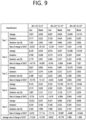
- Tx indicates a thickness of the substrate 1500 in a region x micrometers away from the substrate tip 1510.
- T1 indicates a thickness of the substrate 1500 in a region 1 micrometer away from the substrate tip 1510.
- the separation distance and thickness regarding T1 to T25 are expressed in micrometers.
- the table of FIG. 6 shows values of T4, T16, T20, and T25 that affect physical properties among the values of thickness of the substrate 1500 at a time of forming the cutting edge 1600 of the blade 1000.
- the substrate 1500 has a thickness T4 of 1.16 to 2.06 micrometers measured at a distance of 4 micrometers away from the substrate tip 1510, and the substrate 1500 has a thickness T16 of 3.58 to 6.44 micrometers measured at a distance of 16 micrometers away from the substrate tip 1510.
- the substrate 1500 has a thickness T20 of 4.19 to 7.51 micrometers measured at a distance of 20 micrometers away from the substrate tip 1510, and the substrate 1500 has a thickness T25 of 4.95 to 9.47 micrometers measured at a distance of 25 micrometers away from the substrate tip 1510.
- a shape of the substrate 1500 used as the base material of the blade 1000 has a significant impact on the overall shape, shaving performance, and durability of the blade 1000.
- a thickness in a region of the substrate 1500 relatively close to the substrate tip 1510, such as T1 to T25, may play an important role in determining the characteristics of the blade 1000.
- the first surface 1530 and the second surface 1550 extend toward both sides of the substrate tip 1510.
- the first surface 1530 corresponds to one side facing the skin surface S during shaving
- the second surface 1550 corresponds to the other side opposite to the one side.
- the coating layer 1700 is formed on the first surface 1530 and the second surface 1550.
- the cutting edge 1600 is formed at a tip region of the edge portion 1300, and is formed based on the formation of the substrate 1500 and the coating layer 1700 coated on the substrate 1500.
- the cutting edge 1600 performs a function of substantially cutting the body hair during shaving. At least a portion of the cutting edge 1600 is exposed through a top of the blade housing 1510 and comes into contact with body hair during shaving.
- the coating layer 1700 includes a final tip 1710, a first facet 1730, and a second facet 1740. In addition, the coating layer 1700 further includes a third facet 1760. In addition, the coating layer 1700 further includes a fourth facet 1780 and a fifth facet 1790.
- the coating layer 1700 has a basic structure consisting of hard coating and resin coating. A total thickness of the coating layer 1700 has a range of about 5 nm to about 500 nm.
- the coating layer 1700 of the blade 1000 includes a material based on CrC or Cr.
- the coating layer 1700 may include a layer containing Carbon, a layer containing Boron, a layer containing Nitrogen, or a layer containing Oxide, or a material layer of a combination of at least some of these.
- the final tip 1710 forms the tip of the cutting edge 1710.
- the final tip 1710 is spaced from the skin surface S during shaving.
- the first facet 1730 extends toward one side from the final tip 1710, forming the tip of the cutting edge 1710, and faces the skin surface S during shaving.
- the second facet 1740 extends toward the other side from the final tip 1710.
- the third facet 1760 extends from the first facet 1730.
- the first facet 1730 and the third facet 1760 face the skin surface S.
- the second facet 1740 may face the skin surface S.
- the first facet 1730, the second facet 1740, and the third facet 1760 shown in the present disclosure are formed in a straight line.
- the first facet 1730, the second facet 1740, and the third facet 1760 may have a convex or concave shape.
- the fourth facet 1780 and the fifth facet 1790 are formed symmetrically with each other.
- the fourth facet 1780 extends from the second facet 1740
- the fifth facet 1790 extends from the third facet 1760.
- the blade 1000 according to an embodiment of the present disclosure has an asymmetrical shape.
- the blade 1000 is manufactured to have a symmetrical substrate 1500 and an asymmetrical coating layer 1700.
- the blade 1000 may be manufactured so that the substrate 1500 also has an asymmetrical shape.
- the asymmetric shape of the blade 1000 may be based on the shapes of the first facet 1730 and the third facet 1760.
- the asymmetric shape of the blade 1000 may be formed with including the third facet 1760.
- the first facet 1730 is formed within 1 micrometer from the final tip 1710.
- the second facet 1740 is formed within 50 micrometers from the final tip 1710.
- the third facet 1760 is formed within 50 micrometers from the final tip 1710.
- a first angle ⁇ 1 between the first facet 1730 and the second facet 1740 is an angle formed by the final tip 1710, affecting cut-in of the blade 1000 for the body hair.
- the first angle ⁇ 1 has a value between 50 degrees and 75 degrees, more preferably between 50 degrees and 70 degrees.
- a second angle ⁇ 2 between the first facet 1730 and the third facet 1760 is an angle formed by the area of the blade 1000 facing the skin surface S during shaving, affecting the magnitude of skin irritation to the skin surface S during shaving.
- the second angle ⁇ 2 has a value between 120 degrees and 165 degrees, more preferably between 130 degrees and 160 degrees.
- a third angle ⁇ 3 between an extension line of the second facet 1740 and an extension line of the third facet 1760 is an angle that determines the overall thickness of the blade 1000 after the first facet 1730.
- the third angle ⁇ 3 affects a procedure of the blade 100 to cut the body hair, that is, a procedure following a cut-in procedure.
- the third angle ⁇ 3 has a value between 25 degrees and 50 degrees, more preferably between 30 degrees and 45 degrees.
- the first, second, and third angles ⁇ 1, ⁇ 2, ⁇ 3 collectively determine the asymmetrical shape of the blade 1000, and may be the factors that determine an efficient angle ⁇ which will be described later.
- the third facet 1760 and the fifth facet 1790 may be defined as a first intersection point P.
- a line A2 passing through the first intersection point P and a bisector of the final tip 1710 on a line parallel to the skin surface S may be defined as a second intersection point T.
- a distance between the first intersection point P and the second intersection point T has a value between 1 micrometer and 5 micrometers.
- a distance between the final tip 1710 and the second intersection point T has a value between 2 micrometers and 7 micrometers.
- the distances of the first facet 1730, the second facet 1740, and the third facet 1760 from the final tip 1710 correspond to the optimal values for the asymmetrical shape and reduction in the cutting force.
- the first angle ⁇ 1 between the first facet 1730 and the second facet 1740, the second angle ⁇ 2 between the first facet 1730 and the third facet 1760, and the third angle ⁇ 3 between the extension line of the second facet 1740 and the extension line of the third facet 1760 correspond to the optimal values for the asymmetrical shape and reduction in the cutting force.
- a numerical value indicative of the distance between the first intersection point P and the second intersection point T also corresponds to an optimal value for the asymmetrical shape and reduction in the cutting force.
- the blade 1000 having an asymmetric shape forms a blade angle BA between the skin surface S and a line A1 passing through a bisector of the edge portion 1300 and an efficient angle ⁇ between the skin surface S and a line A2 passing through a bisector of the final tip 1710.
- the efficient angle ⁇ is associated with a direction of force applied to the final tip 1730 when the blade 1000 cuts in the body hair
- the blade angle BA is associated with a direction of force applied to all over the cutting edge 160 after the cut-in of the blade 1000.
- a vector FBA for the blade angle BA and a vector F for efficient angle ⁇ are based on a sum of a vector of a shaving direction FD and a vector of a pressing force FP applied to the skin surface during shaving.
- the blade angle BA is formed greater than the efficient angle ⁇ .
- the efficient angle ⁇ is preferably less than 10 degrees, and the blade angle BA is preferably 14 to 22 degrees, more preferably 17 degrees or less. That is, the blade angle BA is formed greater than the efficient angle ⁇ , as in the aforementioned range of numerical values.
- FIG. 7 shows a case where the efficient angle ⁇ is 9 degrees when the blade angle BA is 17 degrees
- (b) shows a case where the efficient angle ⁇ is 14 degrees when the blade angle BA is 22 degrees
- (c) shows a case where the u efficient angle ⁇ is 19 degrees when the blade angle BA is 27 degrees
- (d) shows a case where the efficient angle ⁇ is 40 degrees when the blade angle BA is 45 degrees.
- the final tip 1710 in each of the cases (b) to (d) may increase a cutting force (increases a cutting resistance) as approaching the skin surface S, thereby resulting in pulling of the body hair and uncomfortable shaving sensation.
- the test result chart in FIG. 9 show Single Hair Cutting Force (SHCF) values measured at five tests in cases where the blade angle BA is 14 degrees and the efficient angle ⁇ is 4 degrees, where the blade angle BA is 22 degrees and the efficient angle ⁇ is 14 degrees, and where the blade angle BA is 30 degrees and the efficient angle ⁇ is 22 degrees.
- SHCF Single Hair Cutting Force
- the SHCF is described on the unit basis of gram force (gf), and is classified into two types including SFCH applied to the body hair and SFCH applied to the blade 1000.
- the SHCF on the body hair side represents a numerical value based on a force applied to the body hair
- the SHCF on the blade side represents a numerical value based on a force applied to the blade 1000.
- a rate of change of SHCF refers to the rate of how much a SHCF value vary in each test with a conventional symmetric blade, especially when a blade angle BA is 22 degrees and the efficient angle ⁇ is 22 degrees.
- the rate of change of SHCF is described on the unit basis of a percentage (%).
- the rate of change of SHCF according to the five tests is -11.234% and -13.109% for the body hair and the blade 1000, respectively.
- the rate of change of SHCF is - 9.820% and -10.778% for the body hair and the blade 1000, respectively.
- the rate of change of SHCF is 1.980% and -1.496% for the body hair and the blade 1000, respectively.
- the cutting force decreases, so that body hair is less pulled during shaving and a user may feel comfortable during shaving.
- the blade angle BA is 14 degrees and the efficient angle ⁇ is 4 degrees and where the blade angle BA is 22 degrees and the efficient angle ⁇ is 14 degrees
- a relatively less cutting force may be provided, compared to the case where the blade angle BA is 30 degrees and the efficient angle ⁇ is 22 degrees. Therefore, it is preferable that the blade angle BA is 14 degrees to 22 degrees as limited in an embodiment of the present disclosure, and the efficient angle ⁇ is relatively smaller than the blade angle BA and less than 10 degrees.
- the experimentally efficient angle ⁇ be less than 10 degrees. That is, if the efficient angle ⁇ is adjusted according to a change in the asymmetric cutting edge 1710 and a change in the blade angle BA and then becomes less than 10 degrees, it is possible to reduce a cutting force and minimize skin irritation.
- the blade angle BA between the skin surface S and the line A1 passing through the bisector of the edge portion 1300 is greater than the efficient angle ⁇ between the skin surface S and the line A2 passing through the bisector of the final tip 1710, so that a cutting force can be reduced according to shaving characteristics and irritation to the skin surface S can be minimized.
Landscapes
- Life Sciences & Earth Sciences (AREA)
- Forests & Forestry (AREA)
- Engineering & Computer Science (AREA)
- Mechanical Engineering (AREA)
- Physics & Mathematics (AREA)
- Geometry (AREA)
- Dry Shavers And Clippers (AREA)
Applications Claiming Priority (2)
| Application Number | Priority Date | Filing Date | Title |
|---|---|---|---|
| KR20220074328 | 2022-06-17 | ||
| KR1020230064840A KR20230173582A (ko) | 2022-06-17 | 2023-05-19 | 면도기 카트리지 |
Publications (1)
| Publication Number | Publication Date |
|---|---|
| EP4292782A1 true EP4292782A1 (de) | 2023-12-20 |
Family
ID=86861947
Family Applications (1)
| Application Number | Title | Priority Date | Filing Date |
|---|---|---|---|
| EP23179729.1A Pending EP4292782A1 (de) | 2022-06-17 | 2023-06-16 | Rasierklingeneinheit |
Country Status (2)
| Country | Link |
|---|---|
| US (1) | US20230405856A1 (de) |
| EP (1) | EP4292782A1 (de) |
Families Citing this family (1)
| Publication number | Priority date | Publication date | Assignee | Title |
|---|---|---|---|---|
| KR102211395B1 (ko) * | 2019-05-22 | 2021-02-03 | 주식회사 도루코 | 면도날 및 면도날 제조방법 |
Citations (4)
| Publication number | Priority date | Publication date | Assignee | Title |
|---|---|---|---|---|
| WO2002100610A1 (en) * | 2001-06-12 | 2002-12-19 | Element Six Limited | Cvd diamond cutting insert |
| EP3895861A1 (de) * | 2020-04-16 | 2021-10-20 | GFD Gesellschaft für Diamantprodukte mbH | Rasiervorrichtung |
| WO2021211811A1 (en) * | 2020-04-16 | 2021-10-21 | The Gillette Company Llc | Razor blade |
| WO2022092544A1 (ko) * | 2020-10-27 | 2022-05-05 | 주식회사 도루코 | 비대칭 면도날 |
-
2023
- 2023-06-16 EP EP23179729.1A patent/EP4292782A1/de active Pending
- 2023-06-16 US US18/336,293 patent/US20230405856A1/en active Pending
Patent Citations (4)
| Publication number | Priority date | Publication date | Assignee | Title |
|---|---|---|---|---|
| WO2002100610A1 (en) * | 2001-06-12 | 2002-12-19 | Element Six Limited | Cvd diamond cutting insert |
| EP3895861A1 (de) * | 2020-04-16 | 2021-10-20 | GFD Gesellschaft für Diamantprodukte mbH | Rasiervorrichtung |
| WO2021211811A1 (en) * | 2020-04-16 | 2021-10-21 | The Gillette Company Llc | Razor blade |
| WO2022092544A1 (ko) * | 2020-10-27 | 2022-05-05 | 주식회사 도루코 | 비대칭 면도날 |
Also Published As
| Publication number | Publication date |
|---|---|
| US20230405856A1 (en) | 2023-12-21 |
Similar Documents
| Publication | Publication Date | Title |
|---|---|---|
| CA2740258C (en) | Razors and shaving cartridges with guard | |
| US10293503B2 (en) | Shaving razors and shaving cartridges | |
| CA2558882C (en) | Shaving cartridges and razors | |
| EP1722939B1 (de) | Rasiereinheiten und rasierapparate | |
| CA2700307C (en) | Shaving system | |
| EP1722937B1 (de) | Nassrasierer und rasiereinheiten | |
| EP4292782A1 (de) | Rasierklingeneinheit | |
| US20230364818A1 (en) | Razor blade having an asymmetrical edge | |
| EP4292783A1 (de) | Razor cartridge | |
| KR20230173582A (ko) | 면도기 카트리지 | |
| KR20230173586A (ko) | 면도기 카트리지 | |
| KR20230173587A (ko) | 면도기 카트리지 | |
| US20240051164A1 (en) | Razor cartridge |
Legal Events
| Date | Code | Title | Description |
|---|---|---|---|
| PUAI | Public reference made under article 153(3) epc to a published international application that has entered the european phase |
Free format text: ORIGINAL CODE: 0009012 |
|
| STAA | Information on the status of an ep patent application or granted ep patent |
Free format text: STATUS: REQUEST FOR EXAMINATION WAS MADE |
|
| 17P | Request for examination filed |
Effective date: 20230616 |
|
| AK | Designated contracting states |
Kind code of ref document: A1 Designated state(s): AL AT BE BG CH CY CZ DE DK EE ES FI FR GB GR HR HU IE IS IT LI LT LU LV MC ME MK MT NL NO PL PT RO RS SE SI SK SM TR |
|
| RBV | Designated contracting states (corrected) |
Designated state(s): AL AT BE BG CH CY CZ DE DK EE ES FI FR GB GR HR HU IE IS IT LI LT LU LV MC ME MK MT NL NO PL PT RO RS SE SI SK SM TR |