EP4135942B1 - Mehrwerkzeug-greiferkopf einer sortiervorrichtung und betriebsverfahren dafür - Google Patents
Mehrwerkzeug-greiferkopf einer sortiervorrichtung und betriebsverfahren dafür Download PDFInfo
- Publication number
- EP4135942B1 EP4135942B1 EP21720572.3A EP21720572A EP4135942B1 EP 4135942 B1 EP4135942 B1 EP 4135942B1 EP 21720572 A EP21720572 A EP 21720572A EP 4135942 B1 EP4135942 B1 EP 4135942B1
- Authority
- EP
- European Patent Office
- Prior art keywords
- gripping
- revolver
- tool
- shaped carrier
- transfer platform
- Prior art date
- Legal status (The legal status is an assumption and is not a legal conclusion. Google has not performed a legal analysis and makes no representation as to the accuracy of the status listed.)
- Active
Links
Images








Classifications
-
- B—PERFORMING OPERATIONS; TRANSPORTING
- B25—HAND TOOLS; PORTABLE POWER-DRIVEN TOOLS; MANIPULATORS
- B25J—MANIPULATORS; CHAMBERS PROVIDED WITH MANIPULATION DEVICES
- B25J15/00—Gripping heads and other end effectors
- B25J15/0052—Gripping heads and other end effectors multiple gripper units or multiple end effectors
- B25J15/0057—Gripping heads and other end effectors multiple gripper units or multiple end effectors mounted on a turret
-
- B—PERFORMING OPERATIONS; TRANSPORTING
- B21—MECHANICAL METAL-WORKING WITHOUT ESSENTIALLY REMOVING MATERIAL; PUNCHING METAL
- B21D—WORKING OR PROCESSING OF SHEET METAL OR METAL TUBES, RODS OR PROFILES WITHOUT ESSENTIALLY REMOVING MATERIAL; PUNCHING METAL
- B21D43/00—Feeding, positioning or storing devices combined with, or arranged in, or specially adapted for use in connection with, apparatus for working or processing sheet metal, metal tubes or metal profiles; Associations therewith of cutting devices
- B21D43/003—Positioning devices
-
- B—PERFORMING OPERATIONS; TRANSPORTING
- B25—HAND TOOLS; PORTABLE POWER-DRIVEN TOOLS; MANIPULATORS
- B25J—MANIPULATORS; CHAMBERS PROVIDED WITH MANIPULATION DEVICES
- B25J15/00—Gripping heads and other end effectors
- B25J15/04—Gripping heads and other end effectors with provision for the remote detachment or exchange of the head or parts thereof
- B25J15/0408—Connections means
- B25J15/0425—Connections means having cams
-
- B—PERFORMING OPERATIONS; TRANSPORTING
- B25—HAND TOOLS; PORTABLE POWER-DRIVEN TOOLS; MANIPULATORS
- B25J—MANIPULATORS; CHAMBERS PROVIDED WITH MANIPULATION DEVICES
- B25J15/00—Gripping heads and other end effectors
- B25J15/04—Gripping heads and other end effectors with provision for the remote detachment or exchange of the head or parts thereof
- B25J15/0408—Connections means
- B25J15/0441—Connections means having vacuum or magnetic means
-
- B—PERFORMING OPERATIONS; TRANSPORTING
- B25—HAND TOOLS; PORTABLE POWER-DRIVEN TOOLS; MANIPULATORS
- B25J—MANIPULATORS; CHAMBERS PROVIDED WITH MANIPULATION DEVICES
- B25J15/00—Gripping heads and other end effectors
- B25J15/04—Gripping heads and other end effectors with provision for the remote detachment or exchange of the head or parts thereof
- B25J15/0491—Gripping heads and other end effectors with provision for the remote detachment or exchange of the head or parts thereof comprising end-effector racks
-
- B—PERFORMING OPERATIONS; TRANSPORTING
- B25—HAND TOOLS; PORTABLE POWER-DRIVEN TOOLS; MANIPULATORS
- B25J—MANIPULATORS; CHAMBERS PROVIDED WITH MANIPULATION DEVICES
- B25J15/00—Gripping heads and other end effectors
- B25J15/06—Gripping heads and other end effectors with vacuum or magnetic holding means
- B25J15/0616—Gripping heads and other end effectors with vacuum or magnetic holding means with vacuum
-
- B—PERFORMING OPERATIONS; TRANSPORTING
- B25—HAND TOOLS; PORTABLE POWER-DRIVEN TOOLS; MANIPULATORS
- B25J—MANIPULATORS; CHAMBERS PROVIDED WITH MANIPULATION DEVICES
- B25J19/00—Accessories fitted to manipulators, e.g. for monitoring, for viewing; Safety devices combined with or specially adapted for use in connection with manipulators
- B25J19/0025—Means for supplying energy to the end effector
- B25J19/0029—Means for supplying energy to the end effector arranged within the different robot elements
- B25J19/0041—Means for supplying energy to the end effector arranged within the different robot elements having rotary connection means
Definitions
- the present invention relates to the field of the handling of sheets in cutting plants.
- the invention relates to a multi-tool gripper head for a handler in a sorting apparatus.
- these machines are equipped with handlers provided with gripping heads which can operate with a plurality of workpieces having different materials, thickness and size.
- handlers provided with gripping heads which can operate with a plurality of workpieces having different materials, thickness and size.
- gripping heads which can operate with a plurality of workpieces having different materials, thickness and size.
- a universal fastening member is hence provided at the end of each gripping head, which can be engaged with a plurality of different operating tools, controlled with a suitable control line or energy line (pneumatic fluid, hydraulic fluid, electric current, ).
- the different tools are tidily stored in a tool carrier area located outside of the operating area, where the gripping heads can be led to from the sorting machine, to collect them, use them in respective operating steps and then release them at the end of a specific working step.
- the step of the operating cycle wherein the gripping head is caused to interact with the tool carrier called 'tool changing step', represents an idle time in the machine operation time and it would be desirable to be able to eliminate it.
- JP S59 19292 discloses changing tool machine having a selecting support cooperating with a mandrel.
- US 2016/0089792 discloses a machine to change end effectors stored on a linear storage, where a picking up head shall be displaced.
- a sorting machine is normally arranged in cooperation with a cutting centre, for example a laser cutting apparatus for metal sheets (not shown).
- the sorting machine has the task of picking up individual raw metal sheets from a storage area, normally arranged horizontally in a stack, and to transfer them to the entry of the cutting apparatus. Once the cutting of a number of shaped workpieces from the metal sheet has been completed, the sorting machine has the further task of picking up the individual workpieces and to transfer them in a sorted manner, possibly stacking them, to appropriate sorting positions. At the end of the workpiece transfer, even the remaining metal sheet scraps are removed by the sorting machine to a disposal location.
- the sorting machine since in the various manufacturing batches the raw sheets, the individual workpieces and the scraps can be of a very different nature, size, shape and weight, the sorting machine must employ a variety of gripping tools.
- the sorting machine makes use, in a manner known per se, of one or more gripping heads provided with gripping tools, mounted at the lower end of a handling arm belonging to a system with displacement axles, at least along two orthogonal axes on the horizontal plane and a vertical axis.
- a gripping head T for a sorting machine consists of a housing frame which houses a plurality of tools.
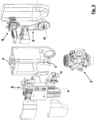
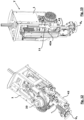
- gripping head T is shown in a compact home condition; the internal structure is not visible due to the presence of a cover body C; in the upper part, gripping head T ends with a flange F fastening to a moving arm of the sorting machine; through fastening flange F the control or energy transfer lines L are caused to pass - for example a vacuum pipe, a compressed air pipe, one or more electric cables and so on - for suitably controlling the members of the gripping head and the tools; in the lower part, gripping head T houses a plurality of gripping tools which will be better described further on.
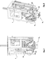
- gripping head T consists of a support frame 1, integral with fastening flange F, whereon a series of operating components is mounted.
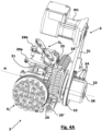
- the operating components comprise a revolver-shaped tool carrier 2, with a relative rotation actuator 3 for driving rotation about an axis H, and a vertical transfer platform 4 with relative linear actuator 5.
- a pneumatic distribution unit 6 is furthermore preferably provided, which puts a single pneumatic line, which runs across flange F, in communication with a plurality of lines to the various control members onboard the head.
- the revolver-shaped tool carrier 2 substantially comprises an engaging body 21, rotatably mounted around a selection axis H and driven into rotation by a pulley 22 actuated by an actuator 3 comprising a gear motor M1 and a toothed belt 31. On engaging body 21 some tools U are coupled, as will be better described further on.
- Selection axis H is preferably horizontal.
- a rotary fluid distributor 23 is preferably provided, fluidly connected to the engaging body 21.
- the distributor 23 has the purpose of giving continuity to a plurality of fluid pipes directed to the tools, connecting a plurality of input fluid connectors 24, arranged in a fixed position on the distributor, with a corresponding plurality of tool sockets 25 provided on the movable gripping tools.
- respective flexible and extendable hoses 25' are provided, for example spirally wound as shown in the drawings, to allow a continuity of the fluid pipe even when the tool is moved far away from rotary distributor 23 (as will be shown further on).
- Rotary fluid distributor 23 preferably hosts in a central position a longitudinal through-hole 26, parallel to axis H, apt to house also an electrical through-wire, to supply other electrical devices, for example electromagnets 27 integral with engagement body 21 or other electromagnets onboard tools U.
- the rotation control of gear motor M1 is preferably alternate, so as to perform rotations smaller than 360° in the two opposite directions. Thereby it is not necessary to provide a sliding contact to maintain the continuity of the electrical wire, but an alternate twist thereof in the two directions is tolerated.
- engagement body 21 is conceived to host four different tools U 1 -U 4 .
- body 21 takes up the shape of a square plate, with four orthogonal sides whereon an equal number of gripping tools U 1 -U 4 are coupled.
- pairs of adjustment holes 28 and an electromagnet 27 are provided on each side.
- Each side is furthermore equipped with a fork having a pair of elastic arms 29a and 29b, one elastically pushed towards the other for defining a gripping action on gripping tools U 1 -U 4 .
- Electromagnet 27 and forks with elastic arms 29a and 29b overall form releasable engagement means, which could even take on different embodiments. They keep tools U 1 -U 4 coupled with engagement body 21, but allow controlled detachment thereof, in the manners and times which are illustrated in the following.
- the various gripping tools U 1 -U 4 are all equipped with a universal fastening base 200 ( fig. 4C ), whereto an active component is fastened which varies according to the type of tool.
- Base 200 is equipped with retaining means arranged so as to securely engage with the corresponding releasable engagement means present on the engaging body 21 of revolver-shaped carrier 2.
- base 200 has a pair of centring pins 201 meant to engage with corresponding centring holes 28 of engaging body 21, as well as a metal insert 202 meant to couple with electromagnets 27.
- a pair of retaining pins 203 is furthermore provided, meant to engage with engagement means provided on transfer platform 4, as will be seen further on.
- the lateral design of base 200 is conceived to cooperate with elastic arms 29a, 29b and to remain securely snap-engaged between them.
- revolver-shaped carrier 2 retains in a releasable manner four different tools, exploiting the engagement of centring pins 201 with centring holes 28 and the retaining snap force imparted by elastic arms 29a, 29b and by electromagnets 27.
- revolver-shaped carrier 2 is attached to three exemplifying gripping tools with different active components:
- Fig. 4D shows a further preferred tool U 5 (for example mountable on the gripping head instead of tool U 3 ), provided with two concentric electromagnets apt to be controlled independently.
- a first central electromagnet is of a circular shape and has a diameter ranging between 25-35 mm: this is meant to collect smaller workpieces (up to a maximum of about 40 kg).
- a second peripheral electromagnet is of an annular shape: it is meant to contribute with an auxiliary force to that of the first electromagnet when the workpiece to be collected exceeds 40 kg of weight, up to a maximum of about 130 kg.
- the activation of the electromagnets can be alternatively controlled on the two or simultaneously.
- a tool with triple-fold geometry and different load carrying capability is thus offered, programmable depending on the workpieces to be collected.
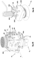
- Fig. 5A shows in detail transfer platform 4 with relative linear actuator 5, both mounted on frame T.
- transfer platform 4 comprises a shelf 41 fastened to a moving slider 42 slidably mounted along a sliding axis Y.
- Sliding axis Y is preferably vertical.
- Shelf 41 is provided with engagement means, with which it can be securely fastened, in a releasable manner, to a selected gripping tool.
- shelf 41 supports cantilevered engagement means, at a certain distance from the moving slider 42 in the direction of the central axis of the gripping head.
- the engagement means are in a central area where they can engage, when desired, with retaining means of gripping tools U 1 -U 5 .
- the releasable engagement means consist of a shaft 43, supported in rotation on a terminal body 41' of shelf 41 and driven into alternate rotation by a pneumatic actuator 44.
- Shaft 43 has at least a portion wherein the crosswise section has two different orthogonal dimensions, a shorter and a longer one: for example, cylindrical-section shaft 43 is provided with two opposite lateral recesses 43a ( fig. 5C ). Shaft 43 is meant to engage with a fork feature defined between the two retaining pins 203 of tools U 1 -U 5 , alternatively offering a larger or a smaller diameter and hence preventing from or allowing, respectively, a relative crosswise disengagement movement.
- the two retaining pins 203 of gripping tools U 1 -U 5 have a narrower-section portion 203'.
- the centre-to-centre distance between the surfaces of the two pins is greater than the smaller dimension of shaft 43 in correspondence of recesses 43a.
- the two retaining pins 203 can freely slide crosswise across shaft 43 in correspondence of recesses 43a, while the crosswise displacement is prevented if the larger section of shaft 43 lies between the two narrower sections 203' of pins 203.
- a pair of opening cam members 46 is installed, arranged on the opposite sides of shaft 43, which are designed to come in contact and spread open elastic arms 29a and 29b in an attachment step.
- Movable slider 42 is controlled in its rectilinear movement by means of a linear actuator 5, for example ball screw 51 driven into rotation by an electric motor 52 by means of a transmission belt 53.
- linear actuator 5 controls movable slider 42 by means of a floating joint 54 which transfers a driving force through an elastic member, for example a helical spring.
- Floating joint 54 has the purpose of compensating any misalignment between the linear actuator and the platform, ensuring that in any case the movement control along axis Y be transmitted to transfer platform 4 without jamming.
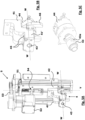
- Actuator 5 is configured ( Fig. 5A ) to move transfer platform 4 between a home position, wherein movable slider 42 is in the upper position, an attaching position, wherein transfer platform 4 is attached to a desired tool (as will be described further on), and one or more operating positions wherein slider 42 descends to lower positions along axis Y and the tool attached to platform 4 is progressively extended below the gripping head.
- movable slider 42 In the home position ( fig. 6A ), movable slider 42 is in its upper position and keeps shelf 41 with shaft 43 in a substantially centred position with respect to revolver-shaped carrier 2: axis W is in the proximity of axis H.
- revolver-shaped carrier 2 can freely rotate around axis H and the tools surround shelf assembly 41 and actuator 44 without interference.
- tools U 1 -U 5 are engaged with support body 21 at a radial distance from rotation axis H sufficient to leave space to shelf assembly 41 and to the actuator 44 thereof.
- movable slider 42 In the attachment position ( fig. 6B ), movable slider 42 is shifted vertically downwards by a measure sufficient to bring the body 41' of shelf assembly 41 in engagement with a selected tool U, that is the tool which is in the lower position on revolver-shaped carrier 2, for example tool U 4 in the drawing.
- retaining pins 203 are engaged with guiding holes 205 and the respective reduced-section areas 203' are in the proximity of the lateral surface of shaft 43.
- shaft 43 is captured or released from the two retaining pins 203.
- shaft 43 is facing its larger diameter to the two opposite retaining pins 203 (as a matter of fact recess 43a is visible in the upper part of the shaft) and hence it is locked between them: in this condition, tool U 4 and transfer platform 4 are made integral, along a horizontal axis parallel to axis W due to the engagement of pins 203 with holes 45, as well as a vertical axis parallel to axis Y due to the engagement of shaft 43 between pins 203.
- shelf assembly 41 can be shifted into operating positions far away from the gripping head, by means of a further translation of slider 42 along vertical axis Y.
- selected tool U is at a sufficient distance from the gripping head to be able to easily act on the workpieces to be collected without being affected by the greater bulk of revolver-shaped carrier 2 and by the entire gripping head T.
- stopping means are preferably provided which, in the travel end operating position, securely fasten slider 42 directly to the structure of frame 1.
- these stopping means are in the shape of a pair of pins 42a integral with slider 42 which abut against a pair of hooks 11 integral with frame 1.
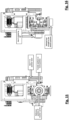
- gripping head T is in a reference condition, with revolver-shaped carrier 2 which takes up a rotation angle of "zero" and transfer platform 4 in the upper home position.
- transfer platform 4 is moved into the attachment position, so as to engage retaining pins 203 with guiding holes 45 and to spread apart elastic arms 29a and 29b.
- the tool is still retained on revolver-shaped carrier 2 by the action of electromagnet 27.
- Pneumatic actuator 44 rotates shaft 43, so as to determine the capture thereof between the two retaining pins 203 and clamp the tool U 4 to the transfer platform 4 also along movement axis Y.
- Electromagnet 27 is deactivated, so as to fully release the tool from revolver-shaped carrier 2.
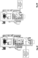
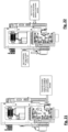
- FIG. 19 an operating step of the tool is shown.
- Slider 42 is extended downwards, bringing tool U 4 into an operating position, for example 200 mm below the attachment position.
- tool U 4 is powered by the control line or by energy transfer consistent with the function thereof, for example a vacuum suction is activated along extensible pipe 25'.
- gripping head T performs the programmed work with the selected tool in an operating position. For example, a fresh metal sheet is collected and it is transferred to the entry of a cutting centre.
- Transfer platform 4 is brought back into the attachment position, the current tool is released from shaft 43 and taken back by electromagnet 27 ( fig. 21 ). After that, transfer platform 4 returns into its home position ( fig. 22 ), the tool is securely engaged again also by elastic arms 29a and 29b and revolver-shaped carrier 2 can rotate again to perform a new selection of the desired tool.
- the tools onboard the revolver-shaped carrier are in any case securely engaged, through electromagnet 27 and elastic arms 29a and 29b, as well as correctly (electrically or pneumatically) supplied: therefore they are perfectly operative and there is no hindrance with respect to the transfer platform in a home position. Therefore that allows to exploit an additional operating mode.
- the tools despite remaining onboard the revolver-shaped carrier, can be used to collect workpieces of a non-excessive weight (because the load is supported by rotation axis H and by releasable engagement means which do not impart a high force, at least in the layout provided in the preferred embodiment).
- the workpieces can also be rotated on a horizontal axis (that is axis H) and then can be brought from a horizontal attitude to an inclined attitude, to be laid onto racks or feeders in a row of adjacent workpieces (instead of stacked one on top of the other).
- a welding station, an anthropomorphic robot or in any case an automation station could benefit from a non-horizontal deposition.
- a workpiece P can be collected in a horizontal attitude and then progressively rotated into a vertical attitude by rotating the revolver-shaped carrier around axis H.
- the gripping head for a sorting apparatus and the relative operating method according to the present invention allow to perfectly reach the set objects.
- the gripping head is arranged so as to have onboard a series of different tools, mounted on a revolver-shaped carrier: therefore the selection of the required tool can occur in a short time, without having to move the gripping head in a peripheral carrier area where to perform the change of tool. That allows understandable time savings in the operating cycle.
- the pick-up action of the selected tool to the transfer platform allows to displace the individual tool at a sufficient distance from the tool carrier, so that no particular work constraints of the tool arise despite the bulk of the same tool carrier.
- the gripping head can hence operate in an identical manner to the conventional single-tool handlers, but in a much faster and flexible manner.
- 'revolver-shaped carrier it is also meant a rotating tool rack, tool carousel, tool turret, but also carrier units for multiple tools with a different selection movement are recomprised, for example a linear movement or movement with more complex displacements, provided they allow a selection of a desired tool which is housed in a certain position of a movable carrier from which it can be picked up and spaced away by the transfer platform.
Landscapes
- Engineering & Computer Science (AREA)
- Mechanical Engineering (AREA)
- Robotics (AREA)
- Manipulator (AREA)
- Discharge Of Articles From Conveyors (AREA)
- Sorting Of Articles (AREA)
- Magnetic Resonance Imaging Apparatus (AREA)
Claims (10)
- Greifkopf (T) eines Handlings in einer Sortiermaschine, bestehend auseinen Tragrahmen (1)eine Vielzahl von Greifwerkzeugen (U1-U5), die mit mindestens einer Buchse (25) für eine Steuerleitung und ersten Haltemitteln (200, 202) ausgestattet sind,ferner umfassendeinen revolverförmigen Träger (2), der an dem Stützrahmen (1) montiert ist und mit einem Eingriffskörper (21) ausgestattet ist, der mit einer Vielzahl von ersten lösbaren Eingriffsmitteln (29a, 29b, 27) versehen ist, die geeignet sind, mit den ersten Haltemitteln (200, 202) eines jeweiligen Greifwerkzeugs der Vielzahl von Greifwerkzeugen (U1-U5) gekoppelt zu werden, wobei die Vielzahl von Greifwerkzeugen (U1-U5) außerdem zweite Haltemittel (203) aufweist,mindestens eine Transferplattform (4), die mit zweiten lösbaren Eingriffsmitteln (43, 45) ausgestattet ist, die mit zweiten Haltemitteln (203) gekoppelt werden könnenwobei die Transferplattform (4) beweglich auf Stützrahmen (1) entlang einer Gleitachse (Y) zwischeneiner Ausgangsstellung,in der die ersten Haltemittel (200, 202) eines ausgewählten Greifwerkzeugs der Vielzahl von Greifwerkzeugen (U1-U5) mit den ersten lösbaren Eingriffsmitteln (29a, 29b, 27) des revolverförmigen Trägers (2) in Eingriff sind,einer Befestigungsstellung,in der die zweiten lösbaren Eingriffsmittel (43, 45) mit den zweiten Haltemittel (203) des ausgewählten Greifwerkzeugs (U1-U5) gekoppelt sind, undeiner Betriebsstellung,in der die ersten Haltemittel (200, 202) des ausgewählten Greifwerkzeugs (U1-U5) von den ersten lösbaren Eingriffsmitteln (29a, 29b, 27) entkoppelt sind und das ausgewählte Greifwerkzeug (U1-U5) von dem revolverförmigen Träger (2) beabstandet ist,und dadurch gekennzeichnet,
dass der Eingriffskörper (21) drehbar um eine Auswahlachse (H) montiert ist, die senkrecht zu der Gleitachse (Y) ist. - Greifkopf (T) nach Anspruch 1, wobei der revolverförmige Träger (2) durch einen rotatorischen Stellglied (3) in verschiedene Auswahlstellungen gesteuert wird.
- Greifkopf (T) nach Anspruch 2, wobei zwischen dem rotatorischen Stellglied (3) und dem drehbaren Träger (2) ein drehbarer Strömungsverteiler (23) vorgesehen ist, um eine Strömungsleitung für die Greifwerkzeuge (U1-U5) von einer festen Position (24) zu den Buchsen (25) für eine Steuerleitung zu verbinden, die drehfest mit dem drehbaren Träger (2) verbunden ist.
- Greifkopf (T) nach Anspruch 1, 2 oder 3, wobei die ersten lösbaren Eingriffsmittel eine Gabel mit elastischen Schnapparmen (29a, 29b) und mindestens einen betätigbaren Elektromagneten (27) umfassen.
- Greifkopf (T) nach einem der vorhergehenden Ansprüche, wobei die Transferplattform (4) eine Regalbaugruppe (41) umfasst, die freitragend auf einem Verschiebungsschlitten (42) montiert ist, der von einem linearen Stellglied (5) gesteuert wird.
- Greifkopf (T) nach Anspruch 5, dadurch gekennzeichnet, dass zwischen dem Verschiebungsschieber (42) und dem linearen Stellglied (5) eine schwimmende Verbindung vorgesehen ist, die geeignet ist, eine Steuerwirkung durch elastische Mittel zu übertragen.
- Greifkopf (T) nach Anspruch 6, wobei die Regalbaugruppe (41) einen Endkörper (41') umfasst, der mit zwei parallelen Führungslöchern (45) ausgestattet ist, die einen senkrechten Gehäusesitz schneiden, in dem eine Welle (43) mit einem Teil, der einen nicht-kreisförmigen Abschnitt (43a) aufweist, drehbar gelagert ist.
- Greifkopf (T) nach Anspruch 7, wobei die Welle (43) durch einen Zweipunkt-Drehantrieb (44) in Drehung versetzt wird.
- Greifkopf (T) nach einem der Ansprüche 5 bis 8, wenn er von 5 abhängig ist, wobei auf dem Regal (41) außerdem ein Paar Öffnungskeile (46) installiert ist, die so angeordnet sind, dass sie mit den elastischen Armen (29a, 29b) in Kontakt kommen und diese auseinanderspreizen
- Verfahren zum Verwenden eines Greifkopfes (T) für ein Handling in Sortiermaschine, wobeider Greifkopf (T) einen Tragrahmen (1) aufweist, auf dem ein revolverförmiger Träger (2) mit einer Vielzahl von Greifwerkzeugen (U1-U5), ein Auswahlstellglied (3) für den revolverförmigen Träger (2), eine Transferplattform (4) und ein lineares Stellglied (5) für die Transferplattform (4) untergebracht sind,wobei die Transferplattform (4) entlang einer Gleitachse (Y) verschiebbar angebracht ist,und dadurch gekennzeichnet, dass sie die SchritteAuswählen eines gewünschten Greifwerkzeugs (U) auf dem revolverförmigen Träger (2) mittels des Auswahlstellglieds (3) durch Drehung um eine Achse (H), die senkrecht zu der Gleitachse (Y) ist,Verschieben der Transferplattform (4) entlang der Gleitachse (Y) mittels des linearen Stellglieds (5) aus einer Ausgangsposition in eine Befestigungsposition, in der sie mit dem ausgewählten Greifwerkzeug (U) gekoppelt ist,Lösen des ausgewählten Greifwerkzeugs (U) von dem revolverförmigen Träger (2) und Überführen desselben einstückig zu der Transferplattform (4) in eine dem revolverförmigen Träger (2) beabstandete BetriebspositionAusführen eines Greifzyklus mit dem ausgewählten Greifwerkzeug (U),umfasst.
Applications Claiming Priority (2)
| Application Number | Priority Date | Filing Date | Title |
|---|---|---|---|
| IT102020000007903A IT202000007903A1 (it) | 2020-04-15 | 2020-04-15 | Testa di presa multiutensile per un'apparecchiatura di sorting |
| PCT/IB2021/053093 WO2021209932A1 (en) | 2020-04-15 | 2021-04-15 | Multi-tool gripper head of a sorting apparatus and operating method thereof |
Publications (2)
| Publication Number | Publication Date |
|---|---|
| EP4135942A1 EP4135942A1 (de) | 2023-02-22 |
| EP4135942B1 true EP4135942B1 (de) | 2025-03-12 |
Family
ID=71170777
Family Applications (1)
| Application Number | Title | Priority Date | Filing Date |
|---|---|---|---|
| EP21720572.3A Active EP4135942B1 (de) | 2020-04-15 | 2021-04-15 | Mehrwerkzeug-greiferkopf einer sortiervorrichtung und betriebsverfahren dafür |
Country Status (9)
| Country | Link |
|---|---|
| US (1) | US12515354B2 (de) |
| EP (1) | EP4135942B1 (de) |
| JP (1) | JP7699146B2 (de) |
| KR (1) | KR20230002412A (de) |
| CN (1) | CN115397633B (de) |
| BR (1) | BR112022019192A2 (de) |
| FI (1) | FI4135942T3 (de) |
| IT (1) | IT202000007903A1 (de) |
| WO (1) | WO2021209932A1 (de) |
Families Citing this family (2)
| Publication number | Priority date | Publication date | Assignee | Title |
|---|---|---|---|---|
| US20260070234A1 (en) * | 2024-09-11 | 2026-03-12 | Ocado Innovation Limited | Robot end effector |
| US20260070233A1 (en) * | 2024-09-11 | 2026-03-12 | Ocado Innovation Limited | Suction cup assembly for a robot end effector |
Family Cites Families (21)
| Publication number | Priority date | Publication date | Assignee | Title |
|---|---|---|---|---|
| US3277568A (en) * | 1964-05-04 | 1966-10-11 | Kearney & Trecker Corp | Machine tool with tool storage and changing apparatus |
| JPS5919292A (ja) | 1982-07-21 | 1984-01-31 | Hitachi Ltd | バイポ−ラ型ram |
| JPS5919292U (ja) * | 1982-07-28 | 1984-02-06 | 日立電子株式会社 | ロボツト用工具交換装置 |
| US4604787A (en) * | 1984-08-15 | 1986-08-12 | Transamerica Delaval Inc. | Tool changer for manipulator arm |
| JPH05293788A (ja) * | 1992-04-17 | 1993-11-09 | Daihen Corp | ロボット手首用ロータリジョイント装置 |
| JPH09131575A (ja) * | 1995-11-10 | 1997-05-20 | Kubota Corp | 物品の選別装置 |
| JP2992639B1 (ja) * | 1998-07-06 | 1999-12-20 | 工業技術院長 | 脱着機構 |
| DE10115467A1 (de) * | 2001-03-29 | 2002-10-02 | Duerr Systems Gmbh | Werkzeugwechselsystem für eine Maschine |
| ITMI20070968A1 (it) | 2007-05-11 | 2008-11-12 | Meccano System S R L | Apparecchiatura di carico/scarico in asservimento ad un centro di taglio di lastre. |
| JP5130509B2 (ja) * | 2010-08-11 | 2013-01-30 | 川田工業株式会社 | 作業ロボット用エンドエフェクタ交換装置およびその一部を具える作業ロボット |
| DE102012022252B4 (de) * | 2012-11-14 | 2015-12-17 | Wolfgang Wieland | Antriebseinheit für einen Werkzeugwechsler |
| US20160089792A1 (en) * | 2014-09-27 | 2016-03-31 | Tactile Automation, Inc. | Magnetically Attached End Effectors |
| CN105128022B (zh) * | 2015-09-10 | 2017-01-18 | 西安交通大学 | 一种机器人智能末端自动更换装置 |
| KR101667221B1 (ko) * | 2016-05-30 | 2016-10-18 | (주)중원기계 | 다관절 로봇의 자동 공구 교환 장치 |
| JP6918535B2 (ja) * | 2017-03-22 | 2021-08-11 | キヤノン株式会社 | ロボット装置、交換ツール、ロボットアーム、ロボット装置を用いた物品の製造方法、ロボット装置の制御方法、制御プログラムおよび記録媒体 |
| CN107088888A (zh) * | 2017-05-23 | 2017-08-25 | 深圳市连硕教育投资管理有限公司 | 一种用于机器人夹具的快换装置及工作台 |
| JP2019084668A (ja) * | 2017-11-01 | 2019-06-06 | 株式会社近藤製作所 | ロータリージョイント |
| CN207656717U (zh) * | 2017-12-25 | 2018-07-27 | 上海闳铖自动化技术有限公司 | 一种机器人快换夹爪 |
| US10902377B2 (en) * | 2018-01-24 | 2021-01-26 | Amazon Technologies, Inc. | Robotic item handling using a variable area manipulator |
| JP6568279B1 (ja) * | 2018-09-04 | 2019-08-28 | 日本製図器工業株式会社 | ロボットハンドおよびロボット |
| IT201800009542A1 (it) * | 2018-10-17 | 2020-04-17 | Astes4 Sa | Utensile e sistema perfezionato per un manipolatore in centri di taglio di lamiere |
-
2020
- 2020-04-15 IT IT102020000007903A patent/IT202000007903A1/it unknown
-
2021
- 2021-04-15 CN CN202180028821.4A patent/CN115397633B/zh active Active
- 2021-04-15 KR KR1020227035701A patent/KR20230002412A/ko active Pending
- 2021-04-15 BR BR112022019192A patent/BR112022019192A2/pt active Search and Examination
- 2021-04-15 JP JP2022562870A patent/JP7699146B2/ja active Active
- 2021-04-15 US US17/918,709 patent/US12515354B2/en active Active
- 2021-04-15 EP EP21720572.3A patent/EP4135942B1/de active Active
- 2021-04-15 WO PCT/IB2021/053093 patent/WO2021209932A1/en not_active Ceased
- 2021-04-15 FI FIEP21720572.3T patent/FI4135942T3/fi active
Also Published As
| Publication number | Publication date |
|---|---|
| FI4135942T3 (fi) | 2025-06-06 |
| JP7699146B2 (ja) | 2025-06-26 |
| IT202000007903A1 (it) | 2021-10-15 |
| CN115397633A (zh) | 2022-11-25 |
| EP4135942A1 (de) | 2023-02-22 |
| CN115397633B (zh) | 2026-01-20 |
| US12515354B2 (en) | 2026-01-06 |
| WO2021209932A1 (en) | 2021-10-21 |
| KR20230002412A (ko) | 2023-01-05 |
| BR112022019192A2 (pt) | 2022-11-01 |
| JP2023522872A (ja) | 2023-06-01 |
| US20230347528A1 (en) | 2023-11-02 |
Similar Documents
| Publication | Publication Date | Title |
|---|---|---|
| CN212686874U (zh) | 一种夹取机构 | |
| WO2021174963A1 (zh) | 自动化生产线及电机转子生产线 | |
| CN101312805B (zh) | 机床 | |
| CN101284379A (zh) | 操作机械手组件 | |
| CN108290300B (zh) | 抽吸框架 | |
| US12515354B2 (en) | Multi-tool gripper head of a sorting apparatus and operating method thereof | |
| CN103801976A (zh) | 自动搬运夹手总成 | |
| CN218612762U (zh) | 一种电控柜智能装配生产线 | |
| CN113828829B (zh) | 轴线加工一体机 | |
| US5860900A (en) | End effector storage station | |
| KR20070119665A (ko) | 로봇 배열 및 이 로봇 배열을 포함한 장치 | |
| CN203751818U (zh) | 自动搬运夹手总成 | |
| CN104044008A (zh) | 工件转运装置 | |
| CN209717187U (zh) | 一种齿坯全自动连线加工系统 | |
| CN111376014B (zh) | 一种卡扣及隔音棉装配设备 | |
| CN223046701U (zh) | 一种料仓式送收料机 | |
| JPS643611B2 (de) | ||
| CN223032280U (zh) | 一对多自动上下料一体机器人装置及使用其的自动化生产线 | |
| CN223371996U (zh) | 工件转运装置及工件加工系统 | |
| CN220179792U (zh) | 一种陶瓷片切割机的自动移料机构 | |
| CN221337383U (zh) | 一种电池焊保护板设备 | |
| CN222892681U (zh) | 窄通道自动上下料机器人装置及其自动化生产线 | |
| CN220698953U (zh) | 刀盘更换装置 | |
| CN220680827U (zh) | 一种自适应可变式机器人手爪 | |
| CN220408096U (zh) | 刀具双面自动水磨加工工作站 |
Legal Events
| Date | Code | Title | Description |
|---|---|---|---|
| STAA | Information on the status of an ep patent application or granted ep patent |
Free format text: STATUS: UNKNOWN |
|
| STAA | Information on the status of an ep patent application or granted ep patent |
Free format text: STATUS: THE INTERNATIONAL PUBLICATION HAS BEEN MADE |
|
| PUAI | Public reference made under article 153(3) epc to a published international application that has entered the european phase |
Free format text: ORIGINAL CODE: 0009012 |
|
| STAA | Information on the status of an ep patent application or granted ep patent |
Free format text: STATUS: REQUEST FOR EXAMINATION WAS MADE |
|
| 17P | Request for examination filed |
Effective date: 20221108 |
|
| AK | Designated contracting states |
Kind code of ref document: A1 Designated state(s): AL AT BE BG CH CY CZ DE DK EE ES FI FR GB GR HR HU IE IS IT LI LT LU LV MC MK MT NL NO PL PT RO RS SE SI SK SM TR |
|
| DAV | Request for validation of the european patent (deleted) | ||
| DAX | Request for extension of the european patent (deleted) | ||
| GRAP | Despatch of communication of intention to grant a patent |
Free format text: ORIGINAL CODE: EPIDOSNIGR1 |
|
| STAA | Information on the status of an ep patent application or granted ep patent |
Free format text: STATUS: GRANT OF PATENT IS INTENDED |
|
| INTG | Intention to grant announced |
Effective date: 20241031 |
|
| GRAS | Grant fee paid |
Free format text: ORIGINAL CODE: EPIDOSNIGR3 |
|
| GRAA | (expected) grant |
Free format text: ORIGINAL CODE: 0009210 |
|
| STAA | Information on the status of an ep patent application or granted ep patent |
Free format text: STATUS: THE PATENT HAS BEEN GRANTED |
|
| AK | Designated contracting states |
Kind code of ref document: B1 Designated state(s): AL AT BE BG CH CY CZ DE DK EE ES FI FR GB GR HR HU IE IS IT LI LT LU LV MC MK MT NL NO PL PT RO RS SE SI SK SM TR |
|
| P01 | Opt-out of the competence of the unified patent court (upc) registered |
Free format text: CASE NUMBER: APP_5827/2025 Effective date: 20250204 |
|
| REG | Reference to a national code |
Ref country code: GB Ref legal event code: FG4D |
|
| REG | Reference to a national code |
Ref country code: CH Ref legal event code: EP |
|
| REG | Reference to a national code |
Ref country code: DE Ref legal event code: R096 Ref document number: 602021027497 Country of ref document: DE |
|
| REG | Reference to a national code |
Ref country code: IE Ref legal event code: FG4D |
|
| REG | Reference to a national code |
Ref country code: FI Ref legal event code: FGE |
|
| PG25 | Lapsed in a contracting state [announced via postgrant information from national office to epo] |
Ref country code: RS Free format text: LAPSE BECAUSE OF FAILURE TO SUBMIT A TRANSLATION OF THE DESCRIPTION OR TO PAY THE FEE WITHIN THE PRESCRIBED TIME-LIMIT Effective date: 20250612 |
|
| PGFP | Annual fee paid to national office [announced via postgrant information from national office to epo] |
Ref country code: DE Payment date: 20250327 Year of fee payment: 5 |
|
| PG25 | Lapsed in a contracting state [announced via postgrant information from national office to epo] |
Ref country code: ES Free format text: LAPSE BECAUSE OF FAILURE TO SUBMIT A TRANSLATION OF THE DESCRIPTION OR TO PAY THE FEE WITHIN THE PRESCRIBED TIME-LIMIT Effective date: 20250312 |
|
| REG | Reference to a national code |
Ref country code: LT Ref legal event code: MG9D |
|
| PG25 | Lapsed in a contracting state [announced via postgrant information from national office to epo] |
Ref country code: NO Free format text: LAPSE BECAUSE OF FAILURE TO SUBMIT A TRANSLATION OF THE DESCRIPTION OR TO PAY THE FEE WITHIN THE PRESCRIBED TIME-LIMIT Effective date: 20250612 |
|
| PG25 | Lapsed in a contracting state [announced via postgrant information from national office to epo] |
Ref country code: HR Free format text: LAPSE BECAUSE OF FAILURE TO SUBMIT A TRANSLATION OF THE DESCRIPTION OR TO PAY THE FEE WITHIN THE PRESCRIBED TIME-LIMIT Effective date: 20250312 |
|
| REG | Reference to a national code |
Ref country code: NL Ref legal event code: MP Effective date: 20250312 |
|
| PG25 | Lapsed in a contracting state [announced via postgrant information from national office to epo] |
Ref country code: LV Free format text: LAPSE BECAUSE OF FAILURE TO SUBMIT A TRANSLATION OF THE DESCRIPTION OR TO PAY THE FEE WITHIN THE PRESCRIBED TIME-LIMIT Effective date: 20250312 |
|
| PG25 | Lapsed in a contracting state [announced via postgrant information from national office to epo] |
Ref country code: BG Free format text: LAPSE BECAUSE OF FAILURE TO SUBMIT A TRANSLATION OF THE DESCRIPTION OR TO PAY THE FEE WITHIN THE PRESCRIBED TIME-LIMIT Effective date: 20250312 Ref country code: GR Free format text: LAPSE BECAUSE OF FAILURE TO SUBMIT A TRANSLATION OF THE DESCRIPTION OR TO PAY THE FEE WITHIN THE PRESCRIBED TIME-LIMIT Effective date: 20250613 |
|
| PGFP | Annual fee paid to national office [announced via postgrant information from national office to epo] |
Ref country code: CH Payment date: 20250501 Year of fee payment: 5 |
|
| REG | Reference to a national code |
Ref country code: AT Ref legal event code: MK05 Ref document number: 1774632 Country of ref document: AT Kind code of ref document: T Effective date: 20250312 |
|
| PG25 | Lapsed in a contracting state [announced via postgrant information from national office to epo] |
Ref country code: NL Free format text: LAPSE BECAUSE OF FAILURE TO SUBMIT A TRANSLATION OF THE DESCRIPTION OR TO PAY THE FEE WITHIN THE PRESCRIBED TIME-LIMIT Effective date: 20250312 |
|
| PG25 | Lapsed in a contracting state [announced via postgrant information from national office to epo] |
Ref country code: SE Free format text: LAPSE BECAUSE OF FAILURE TO SUBMIT A TRANSLATION OF THE DESCRIPTION OR TO PAY THE FEE WITHIN THE PRESCRIBED TIME-LIMIT Effective date: 20250312 |
|
| PG25 | Lapsed in a contracting state [announced via postgrant information from national office to epo] |
Ref country code: SM Free format text: LAPSE BECAUSE OF FAILURE TO SUBMIT A TRANSLATION OF THE DESCRIPTION OR TO PAY THE FEE WITHIN THE PRESCRIBED TIME-LIMIT Effective date: 20250312 |
|
| PG25 | Lapsed in a contracting state [announced via postgrant information from national office to epo] |
Ref country code: PT Free format text: LAPSE BECAUSE OF FAILURE TO SUBMIT A TRANSLATION OF THE DESCRIPTION OR TO PAY THE FEE WITHIN THE PRESCRIBED TIME-LIMIT Effective date: 20250714 |
|
| PG25 | Lapsed in a contracting state [announced via postgrant information from national office to epo] |
Ref country code: PL Free format text: LAPSE BECAUSE OF FAILURE TO SUBMIT A TRANSLATION OF THE DESCRIPTION OR TO PAY THE FEE WITHIN THE PRESCRIBED TIME-LIMIT Effective date: 20250312 |
|
| PG25 | Lapsed in a contracting state [announced via postgrant information from national office to epo] |
Ref country code: AT Free format text: LAPSE BECAUSE OF FAILURE TO SUBMIT A TRANSLATION OF THE DESCRIPTION OR TO PAY THE FEE WITHIN THE PRESCRIBED TIME-LIMIT Effective date: 20250312 |
|
| PG25 | Lapsed in a contracting state [announced via postgrant information from national office to epo] |
Ref country code: CZ Free format text: LAPSE BECAUSE OF FAILURE TO SUBMIT A TRANSLATION OF THE DESCRIPTION OR TO PAY THE FEE WITHIN THE PRESCRIBED TIME-LIMIT Effective date: 20250312 Ref country code: EE Free format text: LAPSE BECAUSE OF FAILURE TO SUBMIT A TRANSLATION OF THE DESCRIPTION OR TO PAY THE FEE WITHIN THE PRESCRIBED TIME-LIMIT Effective date: 20250312 |
|
| PG25 | Lapsed in a contracting state [announced via postgrant information from national office to epo] |
Ref country code: RO Free format text: LAPSE BECAUSE OF FAILURE TO SUBMIT A TRANSLATION OF THE DESCRIPTION OR TO PAY THE FEE WITHIN THE PRESCRIBED TIME-LIMIT Effective date: 20250312 |
|
| PG25 | Lapsed in a contracting state [announced via postgrant information from national office to epo] |
Ref country code: SK Free format text: LAPSE BECAUSE OF FAILURE TO SUBMIT A TRANSLATION OF THE DESCRIPTION OR TO PAY THE FEE WITHIN THE PRESCRIBED TIME-LIMIT Effective date: 20250312 |
|
| PG25 | Lapsed in a contracting state [announced via postgrant information from national office to epo] |
Ref country code: IS Free format text: LAPSE BECAUSE OF FAILURE TO SUBMIT A TRANSLATION OF THE DESCRIPTION OR TO PAY THE FEE WITHIN THE PRESCRIBED TIME-LIMIT Effective date: 20250712 |
|
| PG25 | Lapsed in a contracting state [announced via postgrant information from national office to epo] |
Ref country code: LU Free format text: LAPSE BECAUSE OF NON-PAYMENT OF DUE FEES Effective date: 20250415 |
|
| REG | Reference to a national code |
Ref country code: DE Ref legal event code: R097 Ref document number: 602021027497 Country of ref document: DE |
|
| PG25 | Lapsed in a contracting state [announced via postgrant information from national office to epo] |
Ref country code: MC Free format text: LAPSE BECAUSE OF FAILURE TO SUBMIT A TRANSLATION OF THE DESCRIPTION OR TO PAY THE FEE WITHIN THE PRESCRIBED TIME-LIMIT Effective date: 20250312 |
|
| REG | Reference to a national code |
Ref country code: BE Ref legal event code: MM Effective date: 20250430 |
|
| PG25 | Lapsed in a contracting state [announced via postgrant information from national office to epo] |
Ref country code: DK Free format text: LAPSE BECAUSE OF FAILURE TO SUBMIT A TRANSLATION OF THE DESCRIPTION OR TO PAY THE FEE WITHIN THE PRESCRIBED TIME-LIMIT Effective date: 20250312 |
|
| PG25 | Lapsed in a contracting state [announced via postgrant information from national office to epo] |
Ref country code: BE Free format text: LAPSE BECAUSE OF NON-PAYMENT OF DUE FEES Effective date: 20250430 |
|
| PLBE | No opposition filed within time limit |
Free format text: ORIGINAL CODE: 0009261 |
|
| STAA | Information on the status of an ep patent application or granted ep patent |
Free format text: STATUS: NO OPPOSITION FILED WITHIN TIME LIMIT |
|
| REG | Reference to a national code |
Ref country code: CH Ref legal event code: L10 Free format text: ST27 STATUS EVENT CODE: U-0-0-L10-L00 (AS PROVIDED BY THE NATIONAL OFFICE) Effective date: 20260121 |
|
| 26N | No opposition filed |
Effective date: 20251215 |
|
| GBPC | Gb: european patent ceased through non-payment of renewal fee |
Effective date: 20250612 |
|
| PG25 | Lapsed in a contracting state [announced via postgrant information from national office to epo] |
Ref country code: GB Free format text: LAPSE BECAUSE OF NON-PAYMENT OF DUE FEES Effective date: 20250612 |
|
| PG25 | Lapsed in a contracting state [announced via postgrant information from national office to epo] |
Ref country code: IE Free format text: LAPSE BECAUSE OF NON-PAYMENT OF DUE FEES Effective date: 20250415 |
|
| PGFP | Annual fee paid to national office [announced via postgrant information from national office to epo] |
Ref country code: FI Payment date: 20260310 Year of fee payment: 6 Ref country code: IT Payment date: 20260311 Year of fee payment: 6 |
|
| PGFP | Annual fee paid to national office [announced via postgrant information from national office to epo] |
Ref country code: FR Payment date: 20260310 Year of fee payment: 6 |
|
| REG | Reference to a national code |
Ref country code: CH Ref legal event code: U11 Free format text: ST27 STATUS EVENT CODE: U-0-0-U10-U11 (AS PROVIDED BY THE NATIONAL OFFICE) Effective date: 20260501 |