EP4135872B1 - Filtermembran für einen horizontalen platten- und rahmenfilter, wie eine turmpresse - Google Patents
Filtermembran für einen horizontalen platten- und rahmenfilter, wie eine turmpresse Download PDFInfo
- Publication number
- EP4135872B1 EP4135872B1 EP20931675.1A EP20931675A EP4135872B1 EP 4135872 B1 EP4135872 B1 EP 4135872B1 EP 20931675 A EP20931675 A EP 20931675A EP 4135872 B1 EP4135872 B1 EP 4135872B1
- Authority
- EP
- European Patent Office
- Prior art keywords
- diaphragm
- lateral
- seal lip
- filter
- bead
- Prior art date
- Legal status (The legal status is an assumption and is not a legal conclusion. Google has not performed a legal analysis and makes no representation as to the accuracy of the status listed.)
- Active
Links
Images

Classifications
-
- B—PERFORMING OPERATIONS; TRANSPORTING
- B01—PHYSICAL OR CHEMICAL PROCESSES OR APPARATUS IN GENERAL
- B01D—SEPARATION
- B01D25/00—Filters formed by clamping together several filtering elements or parts of such elements
- B01D25/12—Filter presses, i.e. of the plate or plate and frame type
- B01D25/21—Plate and frame presses
-
- B—PERFORMING OPERATIONS; TRANSPORTING
- B01—PHYSICAL OR CHEMICAL PROCESSES OR APPARATUS IN GENERAL
- B01D—SEPARATION
- B01D25/00—Filters formed by clamping together several filtering elements or parts of such elements
- B01D25/12—Filter presses, i.e. of the plate or plate and frame type
-
- B—PERFORMING OPERATIONS; TRANSPORTING
- B01—PHYSICAL OR CHEMICAL PROCESSES OR APPARATUS IN GENERAL
- B01D—SEPARATION
- B01D25/00—Filters formed by clamping together several filtering elements or parts of such elements
- B01D25/12—Filter presses, i.e. of the plate or plate and frame type
- B01D25/164—Chamber-plate presses, i.e. the sides of the filtering elements being clamped between two successive filtering plates
-
- B—PERFORMING OPERATIONS; TRANSPORTING
- B01—PHYSICAL OR CHEMICAL PROCESSES OR APPARATUS IN GENERAL
- B01D—SEPARATION
- B01D25/00—Filters formed by clamping together several filtering elements or parts of such elements
- B01D25/12—Filter presses, i.e. of the plate or plate and frame type
- B01D25/21—Plate and frame presses
- B01D25/215—Construction of the filter plates, frames
-
- B—PERFORMING OPERATIONS; TRANSPORTING
- B01—PHYSICAL OR CHEMICAL PROCESSES OR APPARATUS IN GENERAL
- B01D—SEPARATION
- B01D25/00—Filters formed by clamping together several filtering elements or parts of such elements
- B01D25/28—Leaching or washing filter cakes in the filter handling the filter cake for purposes other than regenerating
- B01D25/282—Leaching or washing filter cakes in the filter handling the filter cake for purposes other than regenerating for drying
- B01D25/285—Leaching or washing filter cakes in the filter handling the filter cake for purposes other than regenerating for drying by compression using inflatable membranes
-
- B—PERFORMING OPERATIONS; TRANSPORTING
- B01—PHYSICAL OR CHEMICAL PROCESSES OR APPARATUS IN GENERAL
- B01D—SEPARATION
- B01D35/00—Filtering devices having features not specifically covered by groups B01D24/00 - B01D33/00, or for applications not specifically covered by groups B01D24/00 - B01D33/00; Auxiliary devices for filtration; Filter housing constructions
- B01D35/14—Safety devices specially adapted for filtration; Devices for indicating clogging
-
- B—PERFORMING OPERATIONS; TRANSPORTING
- B01—PHYSICAL OR CHEMICAL PROCESSES OR APPARATUS IN GENERAL
- B01D—SEPARATION
- B01D2201/00—Details relating to filtering apparatus
- B01D2201/34—Seals or gaskets for filtering elements
Definitions
- the space between the filter diaphragm may be provided with a pressurized medium to push the diaphragm against a filter cake formed in the filter chamber and to squeeze remaining liquid contents from the filter cake.
- an underpressurized medium may be provided within the space between the filter diaphragm and the filter plate when adjacent filter frame assemblies are space apart from each other (i.e. the filter chamber is opened) during filter cake removal. This is done to prevent the filter diaphragm from hanging out in the space between the adjacent filter frame assemblies in the way of the filter cake being discharged.
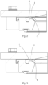
- the diaphragm further comprises, at least on a filter plate -facing side 1d thereof, a continuous seal bead 3.
- the seal bead 3 is provided for sealing the diaphragm against a filter plate.
- the seal bead delimits a planar central portion 1c of the diaphragm on a lateral inside 1a thereof.
- the planar central portion1c is intended to reside within the filter chamber, and to yield without permanent deformation, so as to squeeze filter cake.
- a lateral outside 1b of the diaphragm 1 being defined on a side of the seal bead 3 opposite to the lateral inside 1a. Consequently, a space delimited by the seal bead 3 is formed between the diaphragm 1 and the filter plate.
- the outer seal lip 5 may be configured to seal against a first pressure differential corresponding to a situation in which the space between the filter diaphragm and the filter plate is underpressurized, so as to hold the diaphragm 1 up, and further to leak under a second pressure differential corresponding to a situation in which the space between the filter diaphragm and the filter plate is overpressurized, so as to inflate the diaphragm 1.
- Such a first pressure differential is conventionally much smaller than such a second pressure differential.
- the first pressure differential over the space between the diaphragm and the filter plate lies between 0.01 - 0.10 bar, while the second pressure differential between the space between the diaphragm and the filter plate is between 8 - 20 bar.
- the outer seal lip 5 may be configured to leak when a pressure differential of 0,15 or higher is exerted thereover, for example when an associated frame is in its lower position and an overpressure prevails in the space between the diaphragm and the filter plate.
- the minimum width section W6min of the intermediate portion 6c is defined as a point of the cross-sectional profile of the attachment bead 6 at which the intermediate portion 6c exhibits a smallest laterally extending dimension. That is, the minimum width section W6min is defined at the most narrow point of the intermediate portion 6c, i.e., at a point having the smallest dimension of the intermediate portion 6c along a horizontal direction, transverse to the running direction of the attachment bead 6 and parallel with the general plane of the diaphragm 1.
- an asymmetric concavity with respect to the asymmetry axis A6, is provided on the intermediate portion 6c of the cross-sectional profile of the attachment bead 6. That is, a curved indentation towards the asymmetry axis A6 is provided at the intermediate portion 6c.
- a concavity may be provided on only on the lateral outside of the attachment bead. If a concavity is provided on both the lateral inside 1a and the lateral outside 1b, they may be positioned at different vertical positions on and/or have different curvatures (e.g., different radii of the curvatures)
- the cross-sectional profile of the bead 6 is asymmetric at the distal portion 6a with respect any to vertical line running through the bead 6. Most suitably, the cross-sectional profile of the bead 6 is asymmetric at the distal portion 6a with respect to the asymmetry axis A6
- Fig. 1a is a detailed view of Fig. 1 illustrating the seal bead 3 of the diaphragm in more detail.
- the seal bead comprises an inner seal lip 4 on the lateral inside 1a of the bead, and outer seal lip 5 on the lateral outside 1b of the bead.
- the outer seal lip 5 is elevated higher from the filter plate -facing side 7a than the inner seal lip 4.
- the amount of matter residing on different sides of the line 4', and also the shape of the inner seal lip 4 and the inclination of its side walls have been configured such that the inner seal lip 4 is self-sealing against and is able to better resist deformation against a pressure exerted from a lateral inside 1a, and is not self-sealing and is less able to resist deformation against a pressure exerted from a lateral outside 1b.
Landscapes
- Chemical & Material Sciences (AREA)
- Chemical Kinetics & Catalysis (AREA)
- Filtration Of Liquid (AREA)
- Filtering Of Dispersed Particles In Gases (AREA)
- Separation Using Semi-Permeable Membranes (AREA)
- Diaphragms And Bellows (AREA)
Claims (16)
- Filtermembran (1) für einen horizontalen platten- und rahmenartigen Filter, wie eine Turmpresse, umfassend:- einen flächigen Körper (2) mit einer flexiblen Struktur, und- zumindest auf einer der Filterplatte zugewandten Seite (1d), eine kontinuierliche Dichtwulst (3),- auf einer dem Plattenrahmen zugewandten Seite, entgegengesetzt zu der der Filterplatte zugewandten Seite (1d), eine Befestigungswulst (6) zum Befestigen der Membran (1) an einer auf einem Plattenrahmen ausgebildeten entsprechend geformten Nut,wobei die Dichtwulst einen ebenflächigen mittleren Abschnitt (1c) der Membran auf einer seitlichen Innenseite (1a) derselben abgrenzt, wobei eine seitliche Außenseite (1b) der Membran (1) auf einer der seitlichen Innenseite entgegengesetzten Seite der Dichtwulst (3) definiert ist,wobei die Dichtwulst eine innere Dichtlippe (4) an einer seitlichen Innenseite (1a) der Dichtwulst (3) und eine die innere Dichtlippe (4) umgebende äußere Dichtlippe (5) an einer seitlichen Außenseite (1b) der Dichtwulst (1) umfasst,gekennzeichnet dadurch, dass die äußere Dichtlippe (5) in vertikaler Richtung rechtwinklig zu einer von der Membran (1) definierten allgemeinen Ebene erhöht ist.
- Filtermembran nach Anspruch 1, gekennzeichnet dadurch, dass die äußere Dichtlippe (5) so ausgelegt ist, dass sie sich weg von der der Filterplatte zugewandten Seite (1d) nach außen verformt, wenn von einer seitlichen Außenseite (1b) ein Druck auf sie ausgeübt wird, und dass sie sich hin zu der der Filterplatte zugewandten Seite (1d) nach innen verformt, wenn von einer seitlichen Innenseite (1a) ein Druck auf sie ausgeübt wird, und
wobei die innere Dichtlippe (4) so ausgelegt ist, dass sie sich weg von der der Filterplatte zugewandten Seite (1d) nach außen verformt, wenn von einer seitlichen Innenseite (1a) ein Druck auf sie ausgeübt wird, und dass sie sich hin zu der der Filterplatte zugewandten Seite (1d) nach innen verformt, wenn von einer seitlichen Außenseite (1b) ein Druck auf sie ausgeübt wird. - Filtermembran nach Anspruch 1 oder 2, gekennzeichnet dadurch, dass die äußere Dichtlippe (5) eine erste asymmetrische seitliche Steifigkeit aufweist und die innere Dichtlippe (4) eine zweite asymmetrische seitliche Steifigkeit aufweist,wobei die innere Dichtlippe (4) eine erhöhte seitliche Steifigkeit gegen einen von der seitlichen Innenseite (1a) ausgeübten Druck in Bezug auf eine Quersteifigkeit der inneren Dichtlippe (4) gegen einen von der seitlichen Außenseite (1b) ausgeübten Druck aufweist, undwobei die äußere Dichtlippe (5) eine erhöhte seitliche Steifigkeit gegen einen von einer seitlichen Außenseite (1b) ausgeübten Druck in Bezug auf eine Quersteifigkeit der äußeren Dichtlippe (5) gegen einen von einer seitlichen Innenseite (1a) ausgeübten Druck aufweist.
- Filtermembran (1) nach einem der vorhergehenden Ansprüche 1 bis 3, gekennzeichnet dadurch, dass das Querschnittsprofil der äußeren Dichtlippe (5) einen äußeren Dichtlippensteg (5a) zwischen einem seitlichen Außenrücken (5b) und einem seitlichen Zwischenrücken (3a) definiert, und das Querschnittsprofil der inneren Dichtlippe (4) einen inneren Dichtlippensteg (4a) zwischen einem seitlichen Innenrücken (4b) und dem seitlichen Zwischenrücken (3a) definiert.
- Filtermembran (1) nach Anspruch 4, gekennzeichnetdadurch, dass ein Abschnitt des Querschnittsprofils der inneren Dichtlippe (4), der auf der seitlichen Außenseite (1b) einer vertikalen Linie (4') liegt, die entlang der rechtwinklig zur allgemeinen Ebene der Membran (1) stehenden Richtung durch einen seitlichen Mittelpunkt des inneren Dichtlippenstegs (4a) verläuft, einen größeren Raum einnimmt als ein Abschnitt des Querschnittsprofils der inneren Dichtlippe (4), der auf der seitlichen Innenseite (1a) der Linie (4') liegt, unddadurch, dass ein Abschnitt des Querschnittsprofils der äußeren Dichtlippe (5), der auf der seitlichen Innenseite (1a) einer vertikalen Linie (5') liegt, die entlang der rechtwinklig zur allgemeinen Ebene der Membran (1) stehenden Richtung durch einen seitlichen Mittelpunkt des äußeren Dichtlippenstegs (5a) verläuft, einen größeren Raum einnimmt als ein Abschnitt der äußeren Dichtlippe (5), der auf der seitlichen Außenseite (1b) der Linie (5') liegt.
- Filtermembran (1) nach Anspruch 4 oder 5, gekennzeichnetdadurch, dass das Querschnittsprofil der äußeren Dichtlippe (5) zwischen dem seitlichen Außenrücken (5b) und dem äußeren Dichtlippensteg (5a) eine größere Neigung als zwischen dem seitlichen Zwischenrücken (3a) und dem äußeren Dichtlippensteg (5a) aufweist, unddadurch, dass das Querschnittsprofil der inneren Dichtlippe (4) zwischen dem seitlichen Innenrücken (4b) und dem inneren Dichtlippensteg (4a) eine größere Neigung als zwischen dem seitlichen Zwischenrücken (3a) und dem inneren Dichtlippensteg (4a) aufweist.
- Filtermembran (1) nach einem der vorhergehenden Ansprüche 4 bis 6, gekennzeichnetdadurch, dass eine Neigung, mit der eine seitliche Außenwand der äußeren Dichtlippe (5) mit dem entsprechenden Steg (5a) zusammenkommt, größer ist als eine Neigung, mit der eine seitliche Innenwand der äußeren Dichtlippe (5) mit dem entsprechenden Steg (5a) zusammenkommt, unddadurch, dass eine Neigung, mit der eine seitliche Innenwand der inneren Dichtlippe (4) mit dem entsprechenden Steg (4a) zusammenkommt, größer ist als eine Neigung, mit der eine seitliche Außenwand der inneren Dichtlippe (4) mit dem entsprechenden Steg (4a) zusammenkommt.
- Filtermembran nach einem der vorhergehenden Ansprüche 4 bis 7, gekennzeichnet dadurch, dass die äußere Dichtlippe (5) eine erste Höhe aufweist, die sich in der rechtwinklig zur allgemeinen Ebene der Membran (1) stehenden Richtung ab dem seitlichen Zwischenrücken (3a) von der der Filterplatte zugewandten Seite (1d) der Membran (1) nach außen erstreckt, und die innere Dichtlippe (4) eine zweite Höhe aufweist, die sich in der rechtwinklig zur allgemeinen Ebene der Membran (1) stehenden Richtung ab dem seitlichen Zwischenrücken (3a) von der der Filterplatte zugewandten Seite (1d) der Membran (1) nach außen erstreckt, und
wobei die erste Höhe mindestens 10 % größer als die zweite Höhe ist. - Filtermembran nach einem der vorhergehenden Ansprüche 4 bis 8, gekennzeichnet dadurch, dass die äußere Dichtlippe (5) eine erste Höhe aufweist, die sich in der rechtwinklig zur allgemeinen Ebene der Membran (1) stehenden Richtung ab dem seitlichen Zwischenrücken (3a) von der der Filterplatte zugewandten Seite (1d) der Membran (1) nach außen erstreckt, und die innere Dichtlippe (4) eine zweite Höhe aufweist, die sich in der rechtwinklig zur allgemeinen Ebene der Membran (1) stehenden Richtung ab dem seitlichen Zwischenrücken (3a) von der der Filterplatte zugewandten Seite (1d) der Membran (1) nach außen erstreckt, und
wobei die zweite Höhe mindestens 30 % der ersten Höhe beträgt. - Filtermembran (1) nach einem der vorhergehenden Ansprüche 1 bis 9, gekennzeichnet dadurch, dass sie ferner umfasst: zumindest auf einer dem Plattenrahmen zugewandten Seite (1e), eine Befestigungswulst (6) zum Befestigen der Membran (1) an einem Plattenrahmen des Filters, wobei die Befestigungswulst (6) an der Peripherie der Filtermembran (1) entlang verläuft und den mittleren Abschnitt (1c) der Membran an einer seitlichen Innenseite (1a) der Befestigungswulst (6) abgrenzt,wobei die Befestigungswulst (6) ein Querschnittsprofil mit einem Basisabschnitt (6b), der die Befestigungswulst an der übrigen Membran (1) befestigt, einem fernen Abschnitt (6a) und einem Zwischenabschnitt (6c) zwischen dem Basisabschnitt (6b) und dem fernen Abschnitt (6a) aufweist, so dass die sich seitlich erstreckende Dimension (W6a) des fernen Abschnitts (6a) diejenige des Zwischenabschnitts (W6c) überschreitet,wobei die Befestigungswulst (6) ein asymmetrisches Querschnittsprofil in Bezug zu einer durch einen seitlichen Mittelpunkt eines minimal breiten Abschnitts (W6min) des Zwischenabschnitts (6c) verlaufenden vertikalen Asymmetrieachse (A6) aufweist,wobei die vertikale Asymmetrieachse (A6) rechtwinklig zu einer allgemeinen Ebene der Membran (1) ist, die durch eine Ebenflächigkeit des mittleren Abschnitts (1c) definiert ist, wenn auf einer ebenen Fläche aufliegend,wobei der minimal breite Abschnitt (W6min) des Zwischenabschnitts (6c) als ein Punkt des Querschnittsprofils der Befestigungswulst (6) definiert ist, an dem der Zwischenabschnitt (6c) eine kleinste seitlich verlaufende Dimension aufweist, undwobei sich der ferne Abschnitt (6a) auf der seitlichen Außenseite (1b) weiter von der Asymmetrieachse (A6) entfernt erstreckt als auf der seitlichen Innenseite (1a).
- Filtermembran (1) nach Anspruch 10, gekennzeichnet dadurch, dass das Querschnittsprofil der Befestigungswulst (6) am Zwischenabschnitt (6c) in Bezug auf die vertikale Asymmetrieachse (A6) asymmetrisch ist.
- Filtermembran nach Anspruch 11, gekennzeichnet dadurch, dass eine asymmetrische Konkavität in Bezug auf die Asymmetrieachse (A6) am Zwischenabschnitt (6c) des Querschnittsprofils der Befestigungswulst (6) vorgesehen ist.
- Filtermembran (1) nach einem der vorhergehenden Ansprüche 10 bis 12, gekennzeichnet dadurch, dass das Querschnittsprofil der Befestigungswulst (6) am fernen Abschnitt (6a) in Bezug auf eine beliebige durch die Befestigungswulst (6) verlaufende vertikale Linie asymmetrisch ist.
- Filtermembran (1) nach einem der vorhergehenden Ansprüche 10 bis 13, gekennzeichnet dadurch, dass eine asymmetrische Auswölbung (6d) in Bezug auf die Asymmetrieachse (A6) am fernen Abschnitt (6a) des Querschnittsprofils der Wulst (6) vorgesehen ist.
- Filtermembran (1) nach einem der vorhergehenden Ansprüche 10 bis 14, gekennzeichnet dadurch, dass eine ferne Fläche (6a') des fernen Abschnitts in Bezug auf die allgemeine Ebene der Membran (1) geneigt ist, so dass die ferne Fläche (6a') in einer Richtung von der seitlichen Innenseite (1a) zur seitlichen Außenseite (1b) zum Zwischenabschnitt (6c) hin geneigt ist.
- Filtermembran (1) nach einem der vorhergehenden Ansprüche 10 bis 15, gekennzeichnet dadurch, dass eine Kontur des Querschnittsprofils der Befestigungswulst (6) an jedem Punkt differenzierbar ist.
Applications Claiming Priority (1)
| Application Number | Priority Date | Filing Date | Title |
|---|---|---|---|
| PCT/FI2020/050254 WO2021209679A1 (en) | 2020-04-17 | 2020-04-17 | A filter diaphragm for a horizontal plate and frame -type filter, such as a tower press |
Publications (3)
| Publication Number | Publication Date |
|---|---|
| EP4135872A1 EP4135872A1 (de) | 2023-02-22 |
| EP4135872A4 EP4135872A4 (de) | 2024-01-10 |
| EP4135872B1 true EP4135872B1 (de) | 2025-04-09 |
Family
ID=78084696
Family Applications (1)
| Application Number | Title | Priority Date | Filing Date |
|---|---|---|---|
| EP20931675.1A Active EP4135872B1 (de) | 2020-04-17 | 2020-04-17 | Filtermembran für einen horizontalen platten- und rahmenfilter, wie eine turmpresse |
Country Status (14)
| Country | Link |
|---|---|
| US (1) | US12434176B2 (de) |
| EP (1) | EP4135872B1 (de) |
| CN (2) | CN215995748U (de) |
| AR (1) | AR121866A1 (de) |
| AU (1) | AU2020442210A1 (de) |
| BR (1) | BR112022014761A2 (de) |
| CA (1) | CA3168466A1 (de) |
| ES (1) | ES3034709T3 (de) |
| FI (1) | FI4135872T3 (de) |
| MX (1) | MX2022009248A (de) |
| PE (1) | PE20221617A1 (de) |
| PH (1) | PH12022551743A1 (de) |
| PL (1) | PL4135872T3 (de) |
| WO (1) | WO2021209679A1 (de) |
Family Cites Families (25)
| Publication number | Priority date | Publication date | Assignee | Title |
|---|---|---|---|---|
| JPS567293Y2 (de) * | 1977-01-21 | 1981-02-18 | ||
| JPS53102174A (en) * | 1977-02-16 | 1978-09-06 | Canon Kk | Transporting box |
| DE3520653A1 (de) * | 1985-06-08 | 1986-12-11 | Eberhard Hoesch & Söhne GmbH & Co, 5160 Düren | Membranplatte fuer plattenfilterpressen |
| DE4118620A1 (de) * | 1991-06-06 | 1992-12-10 | Hoesch & Soehne Eberhard | Membranplatte fuer plattenfilterpressen |
| DE19636436C2 (de) * | 1996-09-07 | 1998-10-15 | Hoesch & Soehne Eberhard | Preßmembran für eine Membranplatte einer Plattenfilterpresse |
| CN2339281Y (zh) | 1998-09-30 | 1999-09-22 | 朱兴源 | 嵌合连接的隔膜滤板 |
| DE10024722C2 (de) * | 2000-05-19 | 2003-02-20 | Klinkau & Co Gmbh | Membranfilterplatte für eine Filterpresse sowie Trägerplatte und Membran für eine solche Membranfilterplatte |
| DE10024725C2 (de) * | 2000-05-19 | 2002-11-21 | Klinkau & Co Gmbh | Membranfilterplatte für eine Filterpresse sowie Trägerplatte und Membran für eine solche Membranfilterplatte |
| CN1194787C (zh) * | 2002-10-15 | 2005-03-30 | 朱兴源 | 可控式高恒温滤板及装配工艺 |
| DE10303818B4 (de) * | 2003-01-31 | 2009-04-30 | Outokumpu Oyj | Verfahren zur Montage einer flexiblen Membran, Filterplatte mit Membran und Werkzeug |
| CN2606629Y (zh) * | 2003-03-26 | 2004-03-17 | 秦海江 | 膜片可换式高压压榨隔膜滤板 |
| JP2005144393A (ja) * | 2003-11-19 | 2005-06-09 | Ishigaki Co Ltd | フイルタープレスのダイアフラムろ板 |
| CN201022995Y (zh) * | 2007-05-01 | 2008-02-20 | 杭州兴源过滤机有限公司 | 具有锯齿形密封性能的隔膜滤板 |
| CN201049240Y (zh) * | 2007-05-30 | 2008-04-23 | 杭州兴源过滤机有限公司 | 一种新颖的隔膜滤板 |
| DE102009020317A1 (de) * | 2009-05-07 | 2010-11-18 | Klinkau Gmbh + Co. | Membranträger und Membran für eine Filterpresse |
| CN201543292U (zh) * | 2009-11-07 | 2010-08-11 | 核工业烟台同兴实业有限公司 | 立式全自动隔膜压滤机 |
| DE202010006311U1 (de) * | 2010-05-03 | 2011-06-09 | JVK Filtration Systems GmbH, 91166 | Filterplatte für eine Filterpresse und Filterpaket |
| WO2012127675A1 (ja) * | 2011-03-24 | 2012-09-27 | 株式会社クボタ | ダイヤフラム、ろ板及びフィルタプレス脱水機 |
| CN102240468B (zh) * | 2011-04-11 | 2015-05-13 | 宋家骏 | 立式压滤机的滤板密封装置和滤板 |
| CN205360711U (zh) * | 2015-12-23 | 2016-07-06 | 上海艾思其工程技术有限公司 | 压滤机的滤板隔膜 |
| CN205913823U (zh) * | 2016-07-19 | 2017-02-01 | 康明克斯(北京)机电设备有限公司 | 带有分体式压榨隔膜的压滤机滤板 |
| CN205988597U (zh) * | 2016-08-29 | 2017-03-01 | 莱州市精诚橡胶有限公司 | 一种框式全自动压滤机橡胶隔膜 |
| CN206325274U (zh) * | 2016-12-30 | 2017-07-14 | 佛山市金凯地过滤设备有限公司 | 一种配置高压隔膜滤板的压滤机 |
| CN206965234U (zh) * | 2017-06-28 | 2018-02-06 | 浙江复洁环保设备有限公司 | 一种高弹性隔膜滤板 |
| CN110523116A (zh) * | 2018-05-23 | 2019-12-03 | 杨晶明 | 一种自清理的隔膜滤板及板框压滤机 |
-
2020
- 2020-04-17 MX MX2022009248A patent/MX2022009248A/es unknown
- 2020-04-17 AU AU2020442210A patent/AU2020442210A1/en active Pending
- 2020-04-17 PH PH1/2022/551743A patent/PH12022551743A1/en unknown
- 2020-04-17 BR BR112022014761A patent/BR112022014761A2/pt unknown
- 2020-04-17 CA CA3168466A patent/CA3168466A1/en active Pending
- 2020-04-17 US US17/792,850 patent/US12434176B2/en active Active
- 2020-04-17 PE PE2022001495A patent/PE20221617A1/es unknown
- 2020-04-17 PL PL20931675.1T patent/PL4135872T3/pl unknown
- 2020-04-17 FI FIEP20931675.1T patent/FI4135872T3/fi active
- 2020-04-17 WO PCT/FI2020/050254 patent/WO2021209679A1/en not_active Ceased
- 2020-04-17 EP EP20931675.1A patent/EP4135872B1/de active Active
- 2020-04-17 ES ES20931675T patent/ES3034709T3/es active Active
-
2021
- 2021-04-16 AR ARP210101017A patent/AR121866A1/es active IP Right Grant
- 2021-04-19 CN CN202120801992.3U patent/CN215995748U/zh active Active
- 2021-04-19 CN CN202110417412.5A patent/CN113521820B/zh active Active
Also Published As
| Publication number | Publication date |
|---|---|
| CA3168466A1 (en) | 2021-10-21 |
| PL4135872T3 (pl) | 2025-08-04 |
| ES3034709T3 (en) | 2025-08-21 |
| BR112022014761A2 (pt) | 2022-10-25 |
| CN215995748U (zh) | 2022-03-11 |
| MX2022009248A (es) | 2022-09-07 |
| PE20221617A1 (es) | 2022-10-12 |
| US12434176B2 (en) | 2025-10-07 |
| FI4135872T3 (fi) | 2025-06-26 |
| AU2020442210A1 (en) | 2022-08-11 |
| WO2021209679A1 (en) | 2021-10-21 |
| PH12022551743A1 (en) | 2023-10-23 |
| EP4135872A1 (de) | 2023-02-22 |
| CN113521820A (zh) | 2021-10-22 |
| CN113521820B (zh) | 2023-06-13 |
| AR121866A1 (es) | 2022-07-20 |
| EP4135872A4 (de) | 2024-01-10 |
| US20230043237A1 (en) | 2023-02-09 |
Similar Documents
| Publication | Publication Date | Title |
|---|---|---|
| EP0055007B1 (de) | Verkaufsbehälter | |
| EP1984265B1 (de) | Dosenende für eine dose und solch eine dose | |
| JP2006524785A5 (de) | ||
| EP4135872B1 (de) | Filtermembran für einen horizontalen platten- und rahmenfilter, wie eine turmpresse | |
| ES2297435T3 (es) | Cierre. | |
| OA21275A (en) | A filter diaphragm for a horizontal plate and frame -type filter, such as a tower press. | |
| US9033179B2 (en) | Water tank | |
| ES3034692T3 (en) | A filter plate frame assembly and a horisontal filter press, such as a tower press, having such a plate frame assembly | |
| CN113521819A (zh) | 滤板框架组件、卧式过滤压机和更换其已磨损部件的方法 | |
| AU2020443145A1 (en) | A filter diaphragm, a plate frame, a plate frame assembly, a routing or milling tool set, and a horizontal filter press | |
| ES2993385T3 (en) | A filter plate assembly for a filter press | |
| CN215852685U (zh) | 一种4-羟基丁磺酸的储存桶 | |
| OA21273A (en) | A filter plate frame assembly and a horizontal filter press, such as a tower press, having such a plate frame assembly. | |
| CN119429400B (zh) | 一种易拆装式塑料密封盖 | |
| BR112020003280B1 (pt) | Aparelho de filtragem de líquidos | |
| OA21792A (en) | A Filter Plate Assembly For A Filter Press, And Such A Filter Press. | |
| BR102012010613A2 (pt) | arranjo de fechamento e suspensão para latas. | |
| JPS59128085A (ja) | 艙口蓋の水密装置 |
Legal Events
| Date | Code | Title | Description |
|---|---|---|---|
| STAA | Information on the status of an ep patent application or granted ep patent |
Free format text: STATUS: THE INTERNATIONAL PUBLICATION HAS BEEN MADE |
|
| PUAI | Public reference made under article 153(3) epc to a published international application that has entered the european phase |
Free format text: ORIGINAL CODE: 0009012 |
|
| STAA | Information on the status of an ep patent application or granted ep patent |
Free format text: STATUS: REQUEST FOR EXAMINATION WAS MADE |
|
| 17P | Request for examination filed |
Effective date: 20220715 |
|
| AK | Designated contracting states |
Kind code of ref document: A1 Designated state(s): AL AT BE BG CH CY CZ DE DK EE ES FI FR GB GR HR HU IE IS IT LI LT LU LV MC MK MT NL NO PL PT RO RS SE SI SK SM TR |
|
| DAV | Request for validation of the european patent (deleted) | ||
| DAX | Request for extension of the european patent (deleted) | ||
| P01 | Opt-out of the competence of the unified patent court (upc) registered |
Effective date: 20230627 |
|
| A4 | Supplementary search report drawn up and despatched |
Effective date: 20231212 |
|
| RIC1 | Information provided on ipc code assigned before grant |
Ipc: B01D 25/12 20060101ALI20231206BHEP Ipc: B01D 25/28 20060101ALI20231206BHEP Ipc: B01D 25/21 20060101ALI20231206BHEP Ipc: B01D 25/168 20060101ALI20231206BHEP Ipc: B01D 25/164 20060101AFI20231206BHEP |
|
| GRAP | Despatch of communication of intention to grant a patent |
Free format text: ORIGINAL CODE: EPIDOSNIGR1 |
|
| STAA | Information on the status of an ep patent application or granted ep patent |
Free format text: STATUS: GRANT OF PATENT IS INTENDED |
|
| GRAJ | Information related to disapproval of communication of intention to grant by the applicant or resumption of examination proceedings by the epo deleted |
Free format text: ORIGINAL CODE: EPIDOSDIGR1 |
|
| STAA | Information on the status of an ep patent application or granted ep patent |
Free format text: STATUS: REQUEST FOR EXAMINATION WAS MADE |
|
| GRAP | Despatch of communication of intention to grant a patent |
Free format text: ORIGINAL CODE: EPIDOSNIGR1 |
|
| STAA | Information on the status of an ep patent application or granted ep patent |
Free format text: STATUS: GRANT OF PATENT IS INTENDED |
|
| INTG | Intention to grant announced |
Effective date: 20241021 |
|
| INTC | Intention to grant announced (deleted) | ||
| INTG | Intention to grant announced |
Effective date: 20241113 |
|
| GRAS | Grant fee paid |
Free format text: ORIGINAL CODE: EPIDOSNIGR3 |
|
| GRAA | (expected) grant |
Free format text: ORIGINAL CODE: 0009210 |
|
| STAA | Information on the status of an ep patent application or granted ep patent |
Free format text: STATUS: THE PATENT HAS BEEN GRANTED |
|
| RAP3 | Party data changed (applicant data changed or rights of an application transferred) |
Owner name: METSO FINLAND OY |
|
| AK | Designated contracting states |
Kind code of ref document: B1 Designated state(s): AL AT BE BG CH CY CZ DE DK EE ES FI FR GB GR HR HU IE IS IT LI LT LU LV MC MK MT NL NO PL PT RO RS SE SI SK SM TR |
|
| REG | Reference to a national code |
Ref country code: GB Ref legal event code: FG4D |
|
| REG | Reference to a national code |
Ref country code: CH Ref legal event code: EP |
|
| REG | Reference to a national code |
Ref country code: DE Ref legal event code: R096 Ref document number: 602020049354 Country of ref document: DE |
|
| REG | Reference to a national code |
Ref country code: IE Ref legal event code: FG4D |
|
| REG | Reference to a national code |
Ref country code: FI Ref legal event code: FGE |
|
| PGFP | Annual fee paid to national office [announced via postgrant information from national office to epo] |
Ref country code: FI Payment date: 20250627 Year of fee payment: 6 |
|
| PGFP | Annual fee paid to national office [announced via postgrant information from national office to epo] |
Ref country code: DE Payment date: 20250624 Year of fee payment: 6 |
|
| PGFP | Annual fee paid to national office [announced via postgrant information from national office to epo] |
Ref country code: ES Payment date: 20250625 Year of fee payment: 6 |
|
| PGFP | Annual fee paid to national office [announced via postgrant information from national office to epo] |
Ref country code: NL Payment date: 20250627 Year of fee payment: 6 Ref country code: BE Payment date: 20250626 Year of fee payment: 6 |
|
| REG | Reference to a national code |
Ref country code: NL Ref legal event code: FP |
|
| PGFP | Annual fee paid to national office [announced via postgrant information from national office to epo] |
Ref country code: FR Payment date: 20250630 Year of fee payment: 6 |
|
| REG | Reference to a national code |
Ref country code: SE Ref legal event code: TRGR |
|
| PGFP | Annual fee paid to national office [announced via postgrant information from national office to epo] |
Ref country code: AT Payment date: 20250625 Year of fee payment: 6 |
|
| PGFP | Annual fee paid to national office [announced via postgrant information from national office to epo] |
Ref country code: TR Payment date: 20250626 Year of fee payment: 6 |
|
| PGFP | Annual fee paid to national office [announced via postgrant information from national office to epo] |
Ref country code: SE Payment date: 20250626 Year of fee payment: 6 |
|
| REG | Reference to a national code |
Ref country code: ES Ref legal event code: FG2A Ref document number: 3034709 Country of ref document: ES Kind code of ref document: T3 Effective date: 20250821 |
|
| PG25 | Lapsed in a contracting state [announced via postgrant information from national office to epo] |
Ref country code: PT Free format text: LAPSE BECAUSE OF FAILURE TO SUBMIT A TRANSLATION OF THE DESCRIPTION OR TO PAY THE FEE WITHIN THE PRESCRIBED TIME-LIMIT Effective date: 20250811 |
|
| REG | Reference to a national code |
Ref country code: LT Ref legal event code: MG9D |
|
| PG25 | Lapsed in a contracting state [announced via postgrant information from national office to epo] |
Ref country code: GR Free format text: LAPSE BECAUSE OF FAILURE TO SUBMIT A TRANSLATION OF THE DESCRIPTION OR TO PAY THE FEE WITHIN THE PRESCRIBED TIME-LIMIT Effective date: 20250710 |
|
| PGFP | Annual fee paid to national office [announced via postgrant information from national office to epo] |
Ref country code: NO Payment date: 20250625 Year of fee payment: 6 |
|
| PGFP | Annual fee paid to national office [announced via postgrant information from national office to epo] |
Ref country code: IT Payment date: 20250710 Year of fee payment: 6 Ref country code: PL Payment date: 20250625 Year of fee payment: 6 |
|
| PG25 | Lapsed in a contracting state [announced via postgrant information from national office to epo] |
Ref country code: BG Free format text: LAPSE BECAUSE OF FAILURE TO SUBMIT A TRANSLATION OF THE DESCRIPTION OR TO PAY THE FEE WITHIN THE PRESCRIBED TIME-LIMIT Effective date: 20250409 |
|
| PG25 | Lapsed in a contracting state [announced via postgrant information from national office to epo] |
Ref country code: HR Free format text: LAPSE BECAUSE OF FAILURE TO SUBMIT A TRANSLATION OF THE DESCRIPTION OR TO PAY THE FEE WITHIN THE PRESCRIBED TIME-LIMIT Effective date: 20250409 |
|
| PG25 | Lapsed in a contracting state [announced via postgrant information from national office to epo] |
Ref country code: RS Free format text: LAPSE BECAUSE OF FAILURE TO SUBMIT A TRANSLATION OF THE DESCRIPTION OR TO PAY THE FEE WITHIN THE PRESCRIBED TIME-LIMIT Effective date: 20250709 |
|
| PGFP | Annual fee paid to national office [announced via postgrant information from national office to epo] |
Ref country code: CZ Payment date: 20250627 Year of fee payment: 6 |
|
| PG25 | Lapsed in a contracting state [announced via postgrant information from national office to epo] |
Ref country code: IS Free format text: LAPSE BECAUSE OF FAILURE TO SUBMIT A TRANSLATION OF THE DESCRIPTION OR TO PAY THE FEE WITHIN THE PRESCRIBED TIME-LIMIT Effective date: 20250809 |
|
| PG25 | Lapsed in a contracting state [announced via postgrant information from national office to epo] |
Ref country code: LV Free format text: LAPSE BECAUSE OF FAILURE TO SUBMIT A TRANSLATION OF THE DESCRIPTION OR TO PAY THE FEE WITHIN THE PRESCRIBED TIME-LIMIT Effective date: 20250409 |
|
| REG | Reference to a national code |
Ref country code: CH Ref legal event code: H13 Free format text: ST27 STATUS EVENT CODE: U-0-0-H10-H13 (AS PROVIDED BY THE NATIONAL OFFICE) Effective date: 20251125 |
|
| PG25 | Lapsed in a contracting state [announced via postgrant information from national office to epo] |
Ref country code: LU Free format text: LAPSE BECAUSE OF NON-PAYMENT OF DUE FEES Effective date: 20250417 |
|
| REG | Reference to a national code |
Ref country code: DE Ref legal event code: R097 Ref document number: 602020049354 Country of ref document: DE |
|
| PG25 | Lapsed in a contracting state [announced via postgrant information from national office to epo] |
Ref country code: SM Free format text: LAPSE BECAUSE OF FAILURE TO SUBMIT A TRANSLATION OF THE DESCRIPTION OR TO PAY THE FEE WITHIN THE PRESCRIBED TIME-LIMIT Effective date: 20250409 Ref country code: DK Free format text: LAPSE BECAUSE OF FAILURE TO SUBMIT A TRANSLATION OF THE DESCRIPTION OR TO PAY THE FEE WITHIN THE PRESCRIBED TIME-LIMIT Effective date: 20250409 |
|
| PG25 | Lapsed in a contracting state [announced via postgrant information from national office to epo] |
Ref country code: CH Free format text: LAPSE BECAUSE OF NON-PAYMENT OF DUE FEES Effective date: 20250430 |
|
| PG25 | Lapsed in a contracting state [announced via postgrant information from national office to epo] |
Ref country code: EE Free format text: LAPSE BECAUSE OF FAILURE TO SUBMIT A TRANSLATION OF THE DESCRIPTION OR TO PAY THE FEE WITHIN THE PRESCRIBED TIME-LIMIT Effective date: 20250409 |
|
| PG25 | Lapsed in a contracting state [announced via postgrant information from national office to epo] |
Ref country code: SK Free format text: LAPSE BECAUSE OF FAILURE TO SUBMIT A TRANSLATION OF THE DESCRIPTION OR TO PAY THE FEE WITHIN THE PRESCRIBED TIME-LIMIT Effective date: 20250409 |
|
| PG25 | Lapsed in a contracting state [announced via postgrant information from national office to epo] |
Ref country code: MC Free format text: LAPSE BECAUSE OF FAILURE TO SUBMIT A TRANSLATION OF THE DESCRIPTION OR TO PAY THE FEE WITHIN THE PRESCRIBED TIME-LIMIT Effective date: 20250409 |
|
| PG25 | Lapsed in a contracting state [announced via postgrant information from national office to epo] |
Ref country code: RO Free format text: LAPSE BECAUSE OF FAILURE TO SUBMIT A TRANSLATION OF THE DESCRIPTION OR TO PAY THE FEE WITHIN THE PRESCRIBED TIME-LIMIT Effective date: 20250409 |
|
| PLBE | No opposition filed within time limit |
Free format text: ORIGINAL CODE: 0009261 |
|
| STAA | Information on the status of an ep patent application or granted ep patent |
Free format text: STATUS: NO OPPOSITION FILED WITHIN TIME LIMIT |
|
| REG | Reference to a national code |
Ref country code: CH Ref legal event code: L10 Free format text: ST27 STATUS EVENT CODE: U-0-0-L10-L00 (AS PROVIDED BY THE NATIONAL OFFICE) Effective date: 20260218 |
|
| 26N | No opposition filed |
Effective date: 20260112 |
|
| GBPC | Gb: european patent ceased through non-payment of renewal fee |
Effective date: 20250709 |