EP4135870B1 - Filterplattenrahmenanordnung und horizontale filterpresse, wie eine turmpresse, mit einer solchen plattenrahmenanordnung - Google Patents
Filterplattenrahmenanordnung und horizontale filterpresse, wie eine turmpresse, mit einer solchen plattenrahmenanordnung Download PDFInfo
- Publication number
- EP4135870B1 EP4135870B1 EP20930712.3A EP20930712A EP4135870B1 EP 4135870 B1 EP4135870 B1 EP 4135870B1 EP 20930712 A EP20930712 A EP 20930712A EP 4135870 B1 EP4135870 B1 EP 4135870B1
- Authority
- EP
- European Patent Office
- Prior art keywords
- filter
- filter plate
- subframe
- plate frame
- diaphragm
- Prior art date
- Legal status (The legal status is an assumption and is not a legal conclusion. Google has not performed a legal analysis and makes no representation as to the accuracy of the status listed.)
- Active
Links
Images

Classifications
-
- B—PERFORMING OPERATIONS; TRANSPORTING
- B01—PHYSICAL OR CHEMICAL PROCESSES OR APPARATUS IN GENERAL
- B01D—SEPARATION
- B01D25/00—Filters formed by clamping together several filtering elements or parts of such elements
- B01D25/12—Filter presses, i.e. of the plate or plate and frame type
- B01D25/164—Chamber-plate presses, i.e. the sides of the filtering elements being clamped between two successive filtering plates
-
- B—PERFORMING OPERATIONS; TRANSPORTING
- B01—PHYSICAL OR CHEMICAL PROCESSES OR APPARATUS IN GENERAL
- B01D—SEPARATION
- B01D25/00—Filters formed by clamping together several filtering elements or parts of such elements
- B01D25/12—Filter presses, i.e. of the plate or plate and frame type
- B01D25/21—Plate and frame presses
- B01D25/215—Construction of the filter plates, frames
-
- B—PERFORMING OPERATIONS; TRANSPORTING
- B01—PHYSICAL OR CHEMICAL PROCESSES OR APPARATUS IN GENERAL
- B01D—SEPARATION
- B01D25/00—Filters formed by clamping together several filtering elements or parts of such elements
- B01D25/28—Leaching or washing filter cakes in the filter handling the filter cake for purposes other than regenerating
- B01D25/282—Leaching or washing filter cakes in the filter handling the filter cake for purposes other than regenerating for drying
- B01D25/285—Leaching or washing filter cakes in the filter handling the filter cake for purposes other than regenerating for drying by compression using inflatable membranes
-
- B—PERFORMING OPERATIONS; TRANSPORTING
- B01—PHYSICAL OR CHEMICAL PROCESSES OR APPARATUS IN GENERAL
- B01D—SEPARATION
- B01D35/00—Filtering devices having features not specifically covered by groups B01D24/00 - B01D33/00, or for applications not specifically covered by groups B01D24/00 - B01D33/00; Auxiliary devices for filtration; Filter housing constructions
- B01D35/14—Safety devices specially adapted for filtration; Devices for indicating clogging
Definitions
- the present disclosure relates to horizontal filter presses, such as tower presses, and more particularly to a filter plate frame assembly for such a filter press.
- a horizontally extending filter chamber is formed between adjacent, superimposed filter plate frame assemblies.
- the filter plate assemblies are pressed against each other to seal the filter chamber, and a slurry is introduced into the filter chamber, where filtrate is separated from the slurry by a filter medium.
- the filtrate is conducted to further processing, while the solids content of the slurry form a filter cake in the filter chamber.
- the filter cake is removed from the filter chamber by lifting the filter plate frame assemblies such that they move away from each other (i.e., opening the filter chamber).
- the filter medium typically forming an endless loop in a zig-zag -pattern, is advanced and the filter cake is discharged by dropping it from on top of the filter medium that turns around a roller.
- a diaphragm is often provided for squeezing the filter cake in the filter chamber, so as to extract residual filtrate from the filter cake.
- a diaphragm is typically attached to a filter frame such that it resides vertically between the frame and a filter plate supported by the frame.
- a space between the diaphragm and the filter plate is sealed with a seal bead on the diaphragm, such that a pressurized medium can be introduced into the space.
- the pressurized medium inflates the diaphragm towards the filter chamber thereby squeezing the filter cake.
- the pressure used to inflate the diaphragm typically lies between the range of 8-20 bar over the ambient pressure. The diaphragm can withstand this pressure because the pressure prevailing in the filter chamber (and the filter cake) prevents excessive deformation of the diaphragm, which would lead to damage.
- An object of the present disclosure is to provide a filter plate frame assembly and a horizontal filter press, in which accidental overpressurization of the filter diaphragm is prevented.
- the disclosure is based on the idea of providing a filter plate frame assembly having a separate subframe with a limited vertical travel with respect to the filter frame and filter plate such that the subframe is allowed to drop away from the filter plate when the filter chamber is opened.
- the limited travel of the subframe allows the subframe to be pressed towards the filter plate when the filter chamber is closed, thereby allowing normal operation of the diaphragm for squeezing a filter cake formed in the filter chamber.
- a filter plate frame assembly 1 for a horizontal filter press such as a tower press
- the filter plate frame assembly 1 comprises a rigid filter plate frame 2 defining a closed periphery.
- the purpose of the frame 2 is to support against laterally (i.e. horizontally) directed forces caused by the pressure prevailing in the filter chamber during operation, and also, provide a structure which can be lifted and lowered for opening and closing a filter chamber formed by adjacent filter plate frame assemblies 1.
- the filter plate frame assembly 1 further comprises a filter plate 3 attached onto the filter plate frame 2 on a plate side 1a of the filter plate frame assembly 1, and covering at least an area delimited by the filter plate frame.
- the purpose of the filter plate is to provide support against vertically directed forces caused by the pressure prevailing in the filter chamber during operation, and also, to provide a structure onto which a filtrate vat for collecting filtrate can be formed.
- the filter plate frame assembly 1 further comprises a diaphragm 5 having a continuous seal bead 6 for sealing the diaphragm 5 against the filter plate 3, such that a space delimited by the seal bead 6 is defined between the diaphragm 5 and the plate 3.
- the purpose of the diaphragm is to squeeze residual liquid contents out from the filter cake formed in the filter chamber.
- the seal bead 6 extends around the periphery of diaphragm 5.
- the filter plate frame assembly 1 further comprises a subframe 4 with a central opening 4b having a closed area defining a lateral boundary of an associated filter chamber 4c, when in use.
- the subframe 4 is nested within and laterally delimited by the closed periphery of the filter plate frame 2. This means that the more rigid frame 2 supports the subframe 4 against lateral forces exerted thereon by a pressure prevailing in the filter chamber. Consequently, the subframe can be constructed with a much more light-weight and less rigid structure, as compared to the frame 2.
- the subframe 4 is vertically secured between the filter plate frame 2 and the filter plate 3, such that a vertical free play of the subframe 4 between the plate 3 and the frame 2 allows a limited vertical travel of the subframe 4 with respect to the frame 2 and the plate 3. It should be noted that, in the context of this disclosure, the free play and the limited vertical travel are distinguished from, and exceed, any possible manufacturing clearances.
- the diaphragm 5 is attached to the subframe 4 such that it resides between the subframe 4 and the filter plate 3 and covers an area delimited by the sub-frame 4. Most suitably, the diaphragm 5 resides vertically between the subframe 4 and the filter plate, at least at where the diaphragm 5 is to be sealed against the plate 3.
- the diaphragm As the diaphragm is attached to the subframe 4, it shares the same limited vertical travel with respect to the filter plate 3 as the subframe.
- the subframe 4 has an uppermost position within the limited vertical travel.
- the uppermost position corresponds to a situation in which the subframe 4 is pressed towards the plate 3, i.e., when adjacent filter plate frame assemblies 1 are pressed against each other so as to close a filter chamber formed therebetween.
- the subframe 4 also has a lowermost position within the limited vertical travel. The lowermost position corresponds to a situation in which the subframe 4 is not pressed towards the plate 3, i.e., when adjacent filter plate frame assemblies 1 are away from each other so as to open a filter chamber formed therebetween
- the frame 2 comprises a first bearing surface 2a and the subframe 4 comprises a second bearing surface 4a.
- the subframe 4 In the lowermost position, the subframe 4 is vertically supported by the first bearing surface 2a at the second bearing surface 4a.
- the subframe 4 In the uppermost position, the subframe 4 is not vertically supported by the by the first bearing surface 2a.
- the first bearing surface 2a comprises a groove 2a' and a ridge 2a" and the second bearing surface 4a comprises a groove 4a' and ridge 4a".
- the groove of the first bearing surface 2a' is configured to form fittingly receive the ridge 4a" of the second bearing surface 4a.
- the groove 4a' of the second bearing surface 4a is configured to from-fittingly receive the ridge 2a" of the first bearing surface 2a.
- the filter plate frame assembly can be configured such that, when the sub-frame 4 is the uppermost position, the seal 6 is engaged with the plate 3, and correspondingly, when the subframe 4 is in the lowermost position, the seal 6 is disengaged from the plate 3. This ensures, that pressure can not build up in the space between the diaphragm 5 and the filter plate 3, when the filter chamber is open.
- the filter plate frame assembly can be configured such that, when the subframe 4 is in the lowermost position, the seal bead 6 is engaged with the plate 3 so as to provide sealing against a first pressure differential, and to leak under a second pressure differential, which is higher than the first pressure differential.
- the filter plate frame assembly can be configured such that, when the subframe 4 is in the uppermost position, the seal bead 6 engages with the plate 3 so as to provide sealing also against a third pressure differential, which is higher than the second pressure differential.
- the first pressure differential i.e. an underpressure in the space between the diaphragm 5 and the filter plate 5
- second pressure differential i.e. an overpressure in the space between the diaphragm 5 and the filter plate 3
- a sufficient third pressure differential i.e., an overpressure in the space between the diaphragm 5 and the filter plate 3 is achieved for squeezing the filter cake, when filter chamber is closed.
- Such a first pressure differential is conventionally much smaller than such a third pressure differential.
- the first pressure differential i.e., the underpressure between the ambient pressure and the space between the diaphragm 5 and the filter plate 3 lies between 0.01 - 0.10 bar
- the third pressure differential i.e., the overpressure between ambient pressure and the space between the diaphragm 5 and the filter plate 3 is between 8 - 20 bar.
- the second pressure differential i.e., the overpressure between ambient pressure and the space between the diaphragm 5 and the filter plate 3 is generally only slightly higher than the first pressure differential, typically approx. 0,15 bar.
- only the higher elevated seal lip may be configured to engage with the filter plate 3 when the subframe 4 is in the lowermost position, so as to provide sealing against the first pressure differential and leak under the second pressure differential.
- both the higher elevated and lower elevated seal lip may be configured to engage the filter plate 3 when the subframe 4 is in the uppermost position, so as to seal against the third pressure differential.
- a seal lip elevated higher is provided on a lateral outside of the diaphragm with respect to the seal lip elevated lower.
- the seal lip elevated higher may have a directional self-sealing geometry against an overpressure prevailing on the lateral outside, while the seal lip elevated lower may have a directional self-sealing geometry against an overpressure prevailing on the lateral inside.
- the limited travel of the subframe is less than 10mm. This is because it is undesirable to increase the vertical motion of adjacent plate frame assemblies required to open the filter chamber.
- the total vertical movement of the associated filter press required for opening all filter chambers is the required vertical travel between two adjacent plate frame assemblies multiplied by the number of filter chambers.
- increasing the required vertical travel increases the cycle time of the filtration cycle.
- a horizontal filter press such as a tower press
- the filter comprises a plurality of filter plate frame assemblies according to the first aspect of the present disclosure, as discussed above.
- the filter plate frame assemblies 1 are configured movable towards each other into a closed position in which a filter chamber 4c is formed between adjacent filter plate frame assemblies 1, and away from each to an open position in which adjacent filter plate frame assemblies 1 are spaced apart from each other.
- the filter further comprises a filter medium arranged between adjacent filter plate frame assemblies 1.
- the filter further comprises a translation arrangement for moving the filter plate frame assemblies 1 towards each other so as to form a filter chamber 4c between adjacent filter plate frame assemblies 1, and away from each other so as to open the filter chamber.
- the filter further comprises a feed arrangement for feeding slurry into the filter chamber 4c, a recovering arrangement for recovering filtrate from the filter chamber 4c, and a discharge arrangement for discharging a filter cake formed within the filter chamber 4c.
- the filter press further comprises diaphragm inflation means for providing a pressurized medium into the space between the diaphragm 5 and the filter plate 3 so as to inflate the diaphragm and squeeze a filter cake formed within the filter chamber 4c.
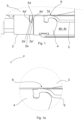
- Fig. 1 schematically illustrates a filter plate frame assembly 1 according to an embodiment of the present disclosure, as seen as a partial cut view.
- the subframe 4 is the lowermost position, corresponding to a situation in which the filter chamber 4c is opened.
- the seal bead 6 has two seal lips, the laterally outer seal lip being elevated higher from the remaining diaphragm 5 than the laterally inner seal lip.
- the laterally outer seal lip engages with the filter plate 3 such that a sufficient underpressure (with respect to the ambient pressure) may be exerted into the space between the diaphragm and the filter plate 3, so as to lift the diaphragm up to facilitate filter cake discharge.
- Fig. 1a illustrates a detailed view of the subframe 4, diaphragm 5 and filter plate 3 of Fig. 1
- Fig. 2a illustrates a detailed view of the subframe, diaphragm and filter plate of Fig. 2
Landscapes
- Chemical & Material Sciences (AREA)
- Chemical Kinetics & Catalysis (AREA)
- Filtration Of Liquid (AREA)
- Filtering Of Dispersed Particles In Gases (AREA)
Claims (9)
- Filterplattenrahmenanordnung (1) für eine horizontale Filterpresse, wie eine Turmpresse, umfassend:einen starren Filterplattenrahmen (2), der eine geschlossene Peripherie definiert, undeine Filterplatte (3), die am Filterplattenrahmen (2) auf der Plattenseite (1a) der Filterplattenrahmenanordnung (1) angebracht ist und mindestens einen durch den Filterplattenrahmen (2) abgegrenzten Bereich abdeckt, undeine Membran (5) mit einer durchgehenden Dichtwulst (6) zum Abdichten der Membran (5) an der Filterplatte (3) dergestalt, dass ein von der Dichtwulst (6) abgegrenzter Raum zwischen der Membran (5) und der Platte (3) definiert wird,gekennzeichnet dadurch, dass die Filterplattenrahmenanordnung (1) ferner einen Unterrahmen (4) mit einer mittigen Öffnung (4b) mit einem geschlossenen Bereich umfasst, der im Gebrauch eine seitliche Begrenzung einer zugehörigen Filterkammer (4c) definiert, undwobei der Unterrahmen (4) in die geschlossene Peripherie des Filterplattenrahmens (2) eingelassen ist und von dieser seitlich abgegrenzt wird,wobei der Unterrahmen (4) zwischen dem Filterplattenrahmen (2) und der Filterplatte (3) vertikal so befestigt ist, dass ein vertikales freies Spiel des Unterrahmens (4) zwischen der Platte (3) und dem Rahmen (2) eine begrenzte vertikale Bewegungsstrecke des Unterrahmens (4) in Bezug auf den Rahmen (2) und die Platte (3) gestattet, undwobei die Membran am Unterrahmen (4) angebracht ist, zwischen dem Unterrahmen (4) und der Filterplatte (3) sitzt und einen vom Unterrahmen (4) abgegrenzten Bereich abdeckt.
- Filterplattenrahmenanordnung (1) nach Anspruch 1, gekennzeichnet dadurch, dass der Unterrahmen (4) eine oberste Position innerhalb der begrenzten vertikalen Bewegungsstrecke aufweist, die einer Situation entspricht, in welcher der Unterrahmen (4) zur Platte (3) hin gedrückt wird, und eine unterste Position innerhalb der begrenzten vertikalen Bewegungsstrecke aufweist, die einer Situation entspricht, in welcher der Unterrahmen (4) nicht zur Platte (3) hin gedrückt wird.
- Filterplattenrahmenanordnung (1) nach Anspruch 2, gekennzeichnet dadurch, dass der Rahmen (2) eine erste Lagerfläche (2a) umfasst und der Unterrahmen (4) eine zweite Lagerfläche (4a) umfasst,wobei in der untersten Position der Unterrahmen (4) durch die erste Lagerfläche (2a) vertikal an der zweiten Lagerfläche (4a) gelagert wird, undwobei in der obersten Position der Unterrahmen (4) nicht durch die erste Lagerfläche vertikal gelagert wird.
- Filterplattenrahmenanordnung (1) nach Anspruch 3, gekennzeichnet dadurch, dass die erste Lagerfläche (2a) eine Nut (2a') und einen Steg (2a") umfasst und die zweite Lagerfläche (4a) eine Nut (4a') und einen Steg (4a") umfasst,
wobei die Nut der ersten Lagerfläche (2a') dazu ausgelegt ist, den Steg (4a") der zweiten Lagerfläche (4a) formschlüssig aufzunehmen, und die Nut (4a') der zweiten Lagerfläche (4a) dazu ausgelegt ist, den Steg (2a") der ersten Lagerfläche (2a) formschlüssig aufzunehmen. - Filterplattenrahmenanordnung nach einem der vorhergehenden Ansprüche 2 bis 4, gekennzeichnet dadurch, dass,wenn der Unterrahmen (4) in der obersten Position ist, die Dichtwulst (6) im Eingriff mit der Platte (3) ist, undwenn der Unterrahmen (4) in der untersten Position ist, die Dichtwulst (6) nicht im Eingriff mit der Platte (3) ist.
- Filterplattenrahmenanordnung nach einem der vorhergehenden Ansprüche 2 bis 4, gekennzeichnet dadurch, dass,wenn der Unterrahmen (4) in der untersten Position ist, die Dichtwulst (6) im Eingriff mit der Platte (3) ist, so dass sie eine Abdichtung gegen eine erste Druckdifferenz bereitstellt und unter einer zweiten, höheren Druckdifferenz durchlässig ist,wenn der Unterrahmen (4) in der obersten Position ist, die Dichtwulst (6) im Eingriff mit der Platte (3) ist, so dass sie eine Abdichtung auch gegen die zweite Druckdifferenz bereitstellt.
- Filterplattenrahmenanordnung (1) nach einem der vorhergehenden Ansprüche 1 bis 6, gekennzeichnet dadurch, dass die begrenzte Bewegungsstrecke des Unterrahmens (4) mindestens 0,5 mm und bevorzugt mindestens 1 mm beträgt.
- Horizontale Filterpresse, wie eine Turmpresse, gekennzeichnet dadurch, dass der Filter umfasst:- eine Mehrzahl von Filterplattenrahmenanordnungen (1) nach einem der vorhergehenden Ansprüche 1 bis 7, wobei die Filterplattenrahmenanordnungen (1) so ausgelegt sind, dass sie aufeinander zu in eine geschlossene Position, in der eine Filterkammer (4c) zwischen angrenzenden Filterplattenrahmenanordnungen (1) ausgebildet wird, und voneinander weg in eine offene Position, in der angrenzende Filterplattenrahmenanordnungen (1) zueinander beabstandet sind, bewegt werden können;- ein zwischen angrenzenden Filterplattenrahmenanordnungen (1) angeordnetes Filtermedium;- eine Translationsanordnung zum Bewegen der Filterplattenrahmenanordnungen (1) aufeinander zu, um eine Filterkammer (4c) zwischen angrenzenden Filterplattenrahmenanordnungen (1) auszubilden, und voneinander weg, um die Filterkammer zu öffnen;- eine Zuführungsanordnung zum Zuführen einer Suspension in die Filterkammer (4c);- eine Rückgewinnungsanordnung zum Rückgewinnen von Filtrat aus der Filterkammer (4c), und- eine Austragsanordnung zum Austragen eines in der Filterkammer (4c) ausgebildeten Filterkuchens.
- Horizontale Filterpresse nach Anspruch 8, gekennzeichnet dadurch, dass die Filterpresse ferner Membranaufblasmittel umfasst, um ein druckbeaufschlagtes Medium in den Raum zwischen der Membran (5) und der Filterplatte (3) einzubringen, um so die Membran aufzublasen und einen in der Filterkammer (4c) ausgebildeten Filterkuchen zusammenzudrücken.
Applications Claiming Priority (1)
| Application Number | Priority Date | Filing Date | Title |
|---|---|---|---|
| PCT/FI2020/050251 WO2021209676A1 (en) | 2020-04-17 | 2020-04-17 | A filter plate frame assembly and a horisontal filter press, such as a tower press, having such a plate frame assembly |
Publications (3)
| Publication Number | Publication Date |
|---|---|
| EP4135870A1 EP4135870A1 (de) | 2023-02-22 |
| EP4135870A4 EP4135870A4 (de) | 2023-12-27 |
| EP4135870B1 true EP4135870B1 (de) | 2025-04-16 |
Family
ID=78085280
Family Applications (1)
| Application Number | Title | Priority Date | Filing Date |
|---|---|---|---|
| EP20930712.3A Active EP4135870B1 (de) | 2020-04-17 | 2020-04-17 | Filterplattenrahmenanordnung und horizontale filterpresse, wie eine turmpresse, mit einer solchen plattenrahmenanordnung |
Country Status (15)
| Country | Link |
|---|---|
| US (1) | US20230048289A1 (de) |
| EP (1) | EP4135870B1 (de) |
| CN (2) | CN113521822B (de) |
| AR (1) | AR121862A1 (de) |
| AU (1) | AU2020442508A1 (de) |
| BR (1) | BR112022014770A2 (de) |
| CA (1) | CA3168695A1 (de) |
| ES (1) | ES3034692T3 (de) |
| FI (1) | FI4135870T3 (de) |
| MX (1) | MX2022009324A (de) |
| PE (1) | PE20221709A1 (de) |
| PH (1) | PH12022551747A1 (de) |
| PL (1) | PL4135870T3 (de) |
| WO (1) | WO2021209676A1 (de) |
| ZA (1) | ZA202208230B (de) |
Families Citing this family (1)
| Publication number | Priority date | Publication date | Assignee | Title |
|---|---|---|---|---|
| PL4135870T3 (pl) * | 2020-04-17 | 2025-07-28 | Metso Finland Oy | Zespół ramy płyty filtrującej oraz pozioma prasa filtrująca, taka jak prasa wieżowa, posiadająca taki zespół ramy płyty |
Family Cites Families (19)
| Publication number | Priority date | Publication date | Assignee | Title |
|---|---|---|---|---|
| DE2322044C2 (de) * | 1973-05-02 | 1983-02-03 | Eberhard Hoesch & Söhne GmbH & Co, 5160 Düren | Preßmembran für Membranplatten |
| GB2069360A (en) * | 1980-02-15 | 1981-08-26 | Moseley Rubber Co Ltd | Membrane plate locking union |
| DE8237298U1 (de) | 1981-11-07 | 1986-01-09 | Kenyon, Jack, Goostrey, Cheshire | Filterplatten-Membranaufbau |
| DE3317235A1 (de) * | 1983-05-11 | 1984-11-15 | Rittershaus & Blecher Gmbh, 5600 Wuppertal | Membranplatte fuer filterpressen |
| DE3520653A1 (de) | 1985-06-08 | 1986-12-11 | Eberhard Hoesch & Söhne GmbH & Co, 5160 Düren | Membranplatte fuer plattenfilterpressen |
| DE3667752D1 (de) * | 1985-07-02 | 1990-02-01 | Brewmar S A | Filteranlage. |
| DE4415274C2 (de) * | 1994-04-30 | 1998-04-30 | Jv Kunststoffwerk | Filterplatte für eine Plattenfilterpresse |
| US5602827A (en) * | 1995-07-28 | 1997-02-11 | Ibm | Method and apparatus for correcting a defect in a token ring network |
| US6180002B1 (en) * | 1998-08-03 | 2001-01-30 | United States Filter Corporation | Filter press with alternating diaphragm squeeze chamber plates and filtration chamber plates |
| DE19905674C1 (de) * | 1999-02-11 | 2000-03-09 | Jv Kunststoffwerk | Filterpresse mit horizontal angeordneten Filterplatten |
| DE102007027035B4 (de) * | 2007-06-08 | 2009-07-02 | Larox Oyj | Filtervorrichtung |
| DE102009020317A1 (de) * | 2009-05-07 | 2010-11-18 | Klinkau Gmbh + Co. | Membranträger und Membran für eine Filterpresse |
| DE202011104970U1 (de) * | 2011-08-25 | 2012-08-30 | Jvk Filtration Systems Gmbh | Filterplatte für eine Filterpresse |
| WO2016097839A1 (en) * | 2014-12-17 | 2016-06-23 | Bilfinger Water Technologies Srl | Filter plate groups for filter press machines |
| CN204522419U (zh) * | 2015-01-09 | 2015-08-05 | 铁岭助驰橡胶密封制品有限公司 | 厢框式橡胶隔膜压滤机 |
| CN105561644B (zh) * | 2016-03-09 | 2017-11-07 | 华南理工大学 | 一种用于压滤机的高干度脱水装置及其脱水方法 |
| EP3473319A1 (de) * | 2017-10-18 | 2019-04-24 | Metso Sweden Ab | Filterplattenanordnung und verfahren zum trennen der feststoffkomponenten von den flüssigen komponenten einer aufschlämmung |
| CN110523116A (zh) * | 2018-05-23 | 2019-12-03 | 杨晶明 | 一种自清理的隔膜滤板及板框压滤机 |
| PL4135870T3 (pl) * | 2020-04-17 | 2025-07-28 | Metso Finland Oy | Zespół ramy płyty filtrującej oraz pozioma prasa filtrująca, taka jak prasa wieżowa, posiadająca taki zespół ramy płyty |
-
2020
- 2020-04-17 PL PL20930712.3T patent/PL4135870T3/pl unknown
- 2020-04-17 AU AU2020442508A patent/AU2020442508A1/en active Pending
- 2020-04-17 ES ES20930712T patent/ES3034692T3/es active Active
- 2020-04-17 EP EP20930712.3A patent/EP4135870B1/de active Active
- 2020-04-17 WO PCT/FI2020/050251 patent/WO2021209676A1/en not_active Ceased
- 2020-04-17 PE PE2022001515A patent/PE20221709A1/es unknown
- 2020-04-17 PH PH1/2022/551747A patent/PH12022551747A1/en unknown
- 2020-04-17 FI FIEP20930712.3T patent/FI4135870T3/fi active
- 2020-04-17 CA CA3168695A patent/CA3168695A1/en active Pending
- 2020-04-17 MX MX2022009324A patent/MX2022009324A/es unknown
- 2020-04-17 US US17/793,548 patent/US20230048289A1/en active Pending
- 2020-04-17 BR BR112022014770A patent/BR112022014770A2/pt unknown
-
2021
- 2021-04-16 AR ARP210101011A patent/AR121862A1/es active IP Right Grant
- 2021-04-19 CN CN202110417630.9A patent/CN113521822B/zh active Active
- 2021-04-19 CN CN202120795882.0U patent/CN216149101U/zh active Active
-
2022
- 2022-07-22 ZA ZA2022/08230A patent/ZA202208230B/en unknown
Also Published As
| Publication number | Publication date |
|---|---|
| BR112022014770A2 (pt) | 2022-10-25 |
| ES3034692T3 (en) | 2025-08-21 |
| MX2022009324A (es) | 2022-08-22 |
| ZA202208230B (en) | 2025-10-29 |
| PH12022551747A1 (en) | 2023-10-23 |
| US20230048289A1 (en) | 2023-02-16 |
| EP4135870A1 (de) | 2023-02-22 |
| PE20221709A1 (es) | 2022-11-02 |
| PL4135870T3 (pl) | 2025-07-28 |
| CN113521822B (zh) | 2023-03-21 |
| CA3168695A1 (en) | 2021-10-21 |
| WO2021209676A1 (en) | 2021-10-21 |
| EP4135870A4 (de) | 2023-12-27 |
| FI4135870T3 (fi) | 2025-05-30 |
| CN113521822A (zh) | 2021-10-22 |
| AU2020442508A1 (en) | 2022-08-11 |
| CN216149101U (zh) | 2022-04-01 |
| AR121862A1 (es) | 2022-07-20 |
Similar Documents
| Publication | Publication Date | Title |
|---|---|---|
| EP4135870B1 (de) | Filterplattenrahmenanordnung und horizontale filterpresse, wie eine turmpresse, mit einer solchen plattenrahmenanordnung | |
| EP4135871B1 (de) | Filterplattenrahmenanordnung, horizontale filterpresse wie etwa eine turmpresse mit einer solchen plattenrahmenanordnung und verfahren zum austausch verschlissener komponenten einer horizontalen filterpresse | |
| NL2016783A (en) | A capsule, a system for preparing a potable beverage from such a capsule and use of such a capsule in a beverage preparation device | |
| US20250057169A1 (en) | De-aeration cavities in a mould member | |
| OA21273A (en) | A filter plate frame assembly and a horizontal filter press, such as a tower press, having such a plate frame assembly. | |
| CN213885127U (zh) | 一种高效压滤脱水装置 | |
| US10780375B2 (en) | Liquid filtration apparatus | |
| KR101139595B1 (ko) | 오토클레이브 장치 | |
| EP4135872B1 (de) | Filtermembran für einen horizontalen platten- und rahmenfilter, wie eine turmpresse | |
| CN107662717A (zh) | 一种快速切换导料方向的医用pvc粒料回收装置 | |
| OA21274A (en) | A filter plate frame assembly, a horizontal filter press, such as a tower press, having such a plate frame assembly, and a method of replacing worn components of horizontal filter press. | |
| CN218608287U (zh) | 一种芝麻油生产加工过滤装置 | |
| US10773189B2 (en) | Liquid filtration apparatus | |
| CN108263746A (zh) | 一种保鲜效果好、操作方便的保鲜盒 | |
| EA038051B1 (ru) | Способ работы фильтр-пресса и фильтр-пресс | |
| US4159247A (en) | Locking filter apparatus and method | |
| JP5817991B2 (ja) | フィルタプレス式脱水機用フィルタ | |
| OA21275A (en) | A filter diaphragm for a horizontal plate and frame -type filter, such as a tower press. | |
| EP4008733B1 (de) | Verdichtungstrockner | |
| WO2019038466A1 (en) | LIQUID FILTRATION APPARATUS | |
| US6036859A (en) | Filter press apparatus | |
| ITPD20110337A1 (it) | Pressa verticale con scarico facilitato del residuo | |
| JPS61161112A (ja) | フイルタプレス | |
| CN113199790A (zh) | 一种高出油率的食用油压榨工艺 | |
| ITRE20090090A1 (it) | Pressa per la pressatura di prodotti alimentari e relativo metodo |
Legal Events
| Date | Code | Title | Description |
|---|---|---|---|
| STAA | Information on the status of an ep patent application or granted ep patent |
Free format text: STATUS: THE INTERNATIONAL PUBLICATION HAS BEEN MADE |
|
| PUAI | Public reference made under article 153(3) epc to a published international application that has entered the european phase |
Free format text: ORIGINAL CODE: 0009012 |
|
| STAA | Information on the status of an ep patent application or granted ep patent |
Free format text: STATUS: REQUEST FOR EXAMINATION WAS MADE |
|
| 17P | Request for examination filed |
Effective date: 20220714 |
|
| AK | Designated contracting states |
Kind code of ref document: A1 Designated state(s): AL AT BE BG CH CY CZ DE DK EE ES FI FR GB GR HR HU IE IS IT LI LT LU LV MC MK MT NL NO PL PT RO RS SE SI SK SM TR |
|
| DAV | Request for validation of the european patent (deleted) | ||
| DAX | Request for extension of the european patent (deleted) | ||
| P01 | Opt-out of the competence of the unified patent court (upc) registered |
Effective date: 20230627 |
|
| A4 | Supplementary search report drawn up and despatched |
Effective date: 20231124 |
|
| RIC1 | Information provided on ipc code assigned before grant |
Ipc: B01D 25/168 20060101ALI20231120BHEP Ipc: B01D 25/28 20060101ALI20231120BHEP Ipc: B01D 25/21 20060101ALI20231120BHEP Ipc: B01D 25/164 20060101AFI20231120BHEP |
|
| GRAP | Despatch of communication of intention to grant a patent |
Free format text: ORIGINAL CODE: EPIDOSNIGR1 |
|
| STAA | Information on the status of an ep patent application or granted ep patent |
Free format text: STATUS: GRANT OF PATENT IS INTENDED |
|
| INTG | Intention to grant announced |
Effective date: 20241022 |
|
| GRAJ | Information related to disapproval of communication of intention to grant by the applicant or resumption of examination proceedings by the epo deleted |
Free format text: ORIGINAL CODE: EPIDOSDIGR1 |
|
| STAA | Information on the status of an ep patent application or granted ep patent |
Free format text: STATUS: REQUEST FOR EXAMINATION WAS MADE |
|
| GRAP | Despatch of communication of intention to grant a patent |
Free format text: ORIGINAL CODE: EPIDOSNIGR1 |
|
| STAA | Information on the status of an ep patent application or granted ep patent |
Free format text: STATUS: GRANT OF PATENT IS INTENDED |
|
| INTC | Intention to grant announced (deleted) | ||
| INTG | Intention to grant announced |
Effective date: 20241212 |
|
| GRAS | Grant fee paid |
Free format text: ORIGINAL CODE: EPIDOSNIGR3 |
|
| GRAA | (expected) grant |
Free format text: ORIGINAL CODE: 0009210 |
|
| STAA | Information on the status of an ep patent application or granted ep patent |
Free format text: STATUS: THE PATENT HAS BEEN GRANTED |
|
| RAP3 | Party data changed (applicant data changed or rights of an application transferred) |
Owner name: METSO FINLAND OY |
|
| AK | Designated contracting states |
Kind code of ref document: B1 Designated state(s): AL AT BE BG CH CY CZ DE DK EE ES FI FR GB GR HR HU IE IS IT LI LT LU LV MC MK MT NL NO PL PT RO RS SE SI SK SM TR |
|
| REG | Reference to a national code |
Ref country code: GB Ref legal event code: FG4D |
|
| REG | Reference to a national code |
Ref country code: CH Ref legal event code: EP Ref country code: DE Ref legal event code: R096 Ref document number: 602020049758 Country of ref document: DE |
|
| REG | Reference to a national code |
Ref country code: IE Ref legal event code: FG4D |
|
| PGFP | Annual fee paid to national office [announced via postgrant information from national office to epo] |
Ref country code: NL Payment date: 20250421 Year of fee payment: 6 |
|
| REG | Reference to a national code |
Ref country code: FI Ref legal event code: FGE |
|
| REG | Reference to a national code |
Ref country code: SE Ref legal event code: TRGR |
|
| PGFP | Annual fee paid to national office [announced via postgrant information from national office to epo] |
Ref country code: FI Payment date: 20250429 Year of fee payment: 6 |
|
| PGFP | Annual fee paid to national office [announced via postgrant information from national office to epo] |
Ref country code: DE Payment date: 20250416 Year of fee payment: 6 |
|
| PGFP | Annual fee paid to national office [announced via postgrant information from national office to epo] |
Ref country code: ES Payment date: 20250509 Year of fee payment: 6 |
|
| PGFP | Annual fee paid to national office [announced via postgrant information from national office to epo] |
Ref country code: NO Payment date: 20250425 Year of fee payment: 6 |
|
| PGFP | Annual fee paid to national office [announced via postgrant information from national office to epo] |
Ref country code: IT Payment date: 20250523 Year of fee payment: 6 Ref country code: BE Payment date: 20250422 Year of fee payment: 6 |
|
| PGFP | Annual fee paid to national office [announced via postgrant information from national office to epo] |
Ref country code: FR Payment date: 20250422 Year of fee payment: 6 |
|
| PGFP | Annual fee paid to national office [announced via postgrant information from national office to epo] |
Ref country code: AT Payment date: 20250425 Year of fee payment: 6 |
|
| PGFP | Annual fee paid to national office [announced via postgrant information from national office to epo] |
Ref country code: TR Payment date: 20250630 Year of fee payment: 6 |
|
| PGFP | Annual fee paid to national office [announced via postgrant information from national office to epo] |
Ref country code: CZ Payment date: 20250415 Year of fee payment: 6 |
|
| REG | Reference to a national code |
Ref country code: NL Ref legal event code: FP |
|
| PGFP | Annual fee paid to national office [announced via postgrant information from national office to epo] |
Ref country code: SE Payment date: 20250411 Year of fee payment: 6 |
|
| REG | Reference to a national code |
Ref country code: ES Ref legal event code: FG2A Ref document number: 3034692 Country of ref document: ES Kind code of ref document: T3 Effective date: 20250821 |
|
| PG25 | Lapsed in a contracting state [announced via postgrant information from national office to epo] |
Ref country code: PT Free format text: LAPSE BECAUSE OF FAILURE TO SUBMIT A TRANSLATION OF THE DESCRIPTION OR TO PAY THE FEE WITHIN THE PRESCRIBED TIME-LIMIT Effective date: 20250818 |
|
| REG | Reference to a national code |
Ref country code: LT Ref legal event code: MG9D |
|
| PG25 | Lapsed in a contracting state [announced via postgrant information from national office to epo] |
Ref country code: GR Free format text: LAPSE BECAUSE OF FAILURE TO SUBMIT A TRANSLATION OF THE DESCRIPTION OR TO PAY THE FEE WITHIN THE PRESCRIBED TIME-LIMIT Effective date: 20250717 |
|
| PGFP | Annual fee paid to national office [announced via postgrant information from national office to epo] |
Ref country code: PL Payment date: 20250430 Year of fee payment: 6 |
|
| PG25 | Lapsed in a contracting state [announced via postgrant information from national office to epo] |
Ref country code: BG Free format text: LAPSE BECAUSE OF FAILURE TO SUBMIT A TRANSLATION OF THE DESCRIPTION OR TO PAY THE FEE WITHIN THE PRESCRIBED TIME-LIMIT Effective date: 20250416 |
|
| PG25 | Lapsed in a contracting state [announced via postgrant information from national office to epo] |
Ref country code: HR Free format text: LAPSE BECAUSE OF FAILURE TO SUBMIT A TRANSLATION OF THE DESCRIPTION OR TO PAY THE FEE WITHIN THE PRESCRIBED TIME-LIMIT Effective date: 20250416 |
|
| PG25 | Lapsed in a contracting state [announced via postgrant information from national office to epo] |
Ref country code: RS Free format text: LAPSE BECAUSE OF FAILURE TO SUBMIT A TRANSLATION OF THE DESCRIPTION OR TO PAY THE FEE WITHIN THE PRESCRIBED TIME-LIMIT Effective date: 20250716 |
|
| PG25 | Lapsed in a contracting state [announced via postgrant information from national office to epo] |
Ref country code: IS Free format text: LAPSE BECAUSE OF FAILURE TO SUBMIT A TRANSLATION OF THE DESCRIPTION OR TO PAY THE FEE WITHIN THE PRESCRIBED TIME-LIMIT Effective date: 20250816 |
|
| PG25 | Lapsed in a contracting state [announced via postgrant information from national office to epo] |
Ref country code: LV Free format text: LAPSE BECAUSE OF FAILURE TO SUBMIT A TRANSLATION OF THE DESCRIPTION OR TO PAY THE FEE WITHIN THE PRESCRIBED TIME-LIMIT Effective date: 20250416 |
|
| REG | Reference to a national code |
Ref country code: CH Ref legal event code: H13 Free format text: ST27 STATUS EVENT CODE: U-0-0-H10-H13 (AS PROVIDED BY THE NATIONAL OFFICE) Effective date: 20251125 |
|
| PG25 | Lapsed in a contracting state [announced via postgrant information from national office to epo] |
Ref country code: LU Free format text: LAPSE BECAUSE OF NON-PAYMENT OF DUE FEES Effective date: 20250417 |
|
| PG25 | Lapsed in a contracting state [announced via postgrant information from national office to epo] |
Ref country code: SM Free format text: LAPSE BECAUSE OF FAILURE TO SUBMIT A TRANSLATION OF THE DESCRIPTION OR TO PAY THE FEE WITHIN THE PRESCRIBED TIME-LIMIT Effective date: 20250416 Ref country code: DK Free format text: LAPSE BECAUSE OF FAILURE TO SUBMIT A TRANSLATION OF THE DESCRIPTION OR TO PAY THE FEE WITHIN THE PRESCRIBED TIME-LIMIT Effective date: 20250416 |
|
| PG25 | Lapsed in a contracting state [announced via postgrant information from national office to epo] |
Ref country code: CH Free format text: LAPSE BECAUSE OF NON-PAYMENT OF DUE FEES Effective date: 20250430 |
|
| REG | Reference to a national code |
Ref country code: DE Ref legal event code: R097 Ref document number: 602020049758 Country of ref document: DE |
|
| PG25 | Lapsed in a contracting state [announced via postgrant information from national office to epo] |
Ref country code: EE Free format text: LAPSE BECAUSE OF FAILURE TO SUBMIT A TRANSLATION OF THE DESCRIPTION OR TO PAY THE FEE WITHIN THE PRESCRIBED TIME-LIMIT Effective date: 20250416 |
|
| PG25 | Lapsed in a contracting state [announced via postgrant information from national office to epo] |
Ref country code: SK Free format text: LAPSE BECAUSE OF FAILURE TO SUBMIT A TRANSLATION OF THE DESCRIPTION OR TO PAY THE FEE WITHIN THE PRESCRIBED TIME-LIMIT Effective date: 20250416 |
|
| PG25 | Lapsed in a contracting state [announced via postgrant information from national office to epo] |
Ref country code: MC Free format text: LAPSE BECAUSE OF FAILURE TO SUBMIT A TRANSLATION OF THE DESCRIPTION OR TO PAY THE FEE WITHIN THE PRESCRIBED TIME-LIMIT Effective date: 20250416 |
|
| PG25 | Lapsed in a contracting state [announced via postgrant information from national office to epo] |
Ref country code: RO Free format text: LAPSE BECAUSE OF FAILURE TO SUBMIT A TRANSLATION OF THE DESCRIPTION OR TO PAY THE FEE WITHIN THE PRESCRIBED TIME-LIMIT Effective date: 20250416 |
|
| PLBE | No opposition filed within time limit |
Free format text: ORIGINAL CODE: 0009261 |
|
| STAA | Information on the status of an ep patent application or granted ep patent |
Free format text: STATUS: NO OPPOSITION FILED WITHIN TIME LIMIT |
|
| REG | Reference to a national code |
Ref country code: CH Ref legal event code: L10 Free format text: ST27 STATUS EVENT CODE: U-0-0-L10-L00 (AS PROVIDED BY THE NATIONAL OFFICE) Effective date: 20260225 |
|
| 26N | No opposition filed |
Effective date: 20260119 |
|
| GBPC | Gb: european patent ceased through non-payment of renewal fee |
Effective date: 20250716 |