EP4008733B1 - Verdichtungstrockner - Google Patents
Verdichtungstrockner Download PDFInfo
- Publication number
- EP4008733B1 EP4008733B1 EP21835924.8A EP21835924A EP4008733B1 EP 4008733 B1 EP4008733 B1 EP 4008733B1 EP 21835924 A EP21835924 A EP 21835924A EP 4008733 B1 EP4008733 B1 EP 4008733B1
- Authority
- EP
- European Patent Office
- Prior art keywords
- guide
- slurry
- compression type
- plate
- type dehydrator
- Prior art date
- Legal status (The legal status is an assumption and is not a legal conclusion. Google has not performed a legal analysis and makes no representation as to the accuracy of the status listed.)
- Active
Links
Images


Classifications
-
- B—PERFORMING OPERATIONS; TRANSPORTING
- B30—PRESSES
- B30B—PRESSES IN GENERAL
- B30B7/00—Presses characterised by a particular arrangement of the pressing members
- B30B7/02—Presses characterised by a particular arrangement of the pressing members having several platens arranged one above the other
- B30B7/023—Feeding or discharging means
-
- B—PERFORMING OPERATIONS; TRANSPORTING
- B30—PRESSES
- B30B—PRESSES IN GENERAL
- B30B9/00—Presses specially adapted for particular purposes
- B30B9/02—Presses specially adapted for particular purposes for squeezing-out liquid from liquid-containing material, e.g. juice from fruits, oil from oil-containing material
- B30B9/04—Presses specially adapted for particular purposes for squeezing-out liquid from liquid-containing material, e.g. juice from fruits, oil from oil-containing material using press rams
- B30B9/06—Presses specially adapted for particular purposes for squeezing-out liquid from liquid-containing material, e.g. juice from fruits, oil from oil-containing material using press rams co-operating with permeable casings or strainers
-
- B—PERFORMING OPERATIONS; TRANSPORTING
- B30—PRESSES
- B30B—PRESSES IN GENERAL
- B30B9/00—Presses specially adapted for particular purposes
- B30B9/02—Presses specially adapted for particular purposes for squeezing-out liquid from liquid-containing material, e.g. juice from fruits, oil from oil-containing material
- B30B9/04—Presses specially adapted for particular purposes for squeezing-out liquid from liquid-containing material, e.g. juice from fruits, oil from oil-containing material using press rams
- B30B9/10—Presses specially adapted for particular purposes for squeezing-out liquid from liquid-containing material, e.g. juice from fruits, oil from oil-containing material using press rams without use of a casing
- B30B9/105—Presses specially adapted for particular purposes for squeezing-out liquid from liquid-containing material, e.g. juice from fruits, oil from oil-containing material using press rams without use of a casing using a press ram co-operating with an intermittently moved endless conveyor
-
- B—PERFORMING OPERATIONS; TRANSPORTING
- B30—PRESSES
- B30B—PRESSES IN GENERAL
- B30B9/00—Presses specially adapted for particular purposes
- B30B9/02—Presses specially adapted for particular purposes for squeezing-out liquid from liquid-containing material, e.g. juice from fruits, oil from oil-containing material
- B30B9/26—Permeable casings or strainers
- B30B9/265—Press cloths
-
- C—CHEMISTRY; METALLURGY
- C08—ORGANIC MACROMOLECULAR COMPOUNDS; THEIR PREPARATION OR CHEMICAL WORKING-UP; COMPOSITIONS BASED THEREON
- C08F—MACROMOLECULAR COMPOUNDS OBTAINED BY REACTIONS ONLY INVOLVING CARBON-TO-CARBON UNSATURATED BONDS
- C08F6/00—Post-polymerisation treatments
-
- C—CHEMISTRY; METALLURGY
- C08—ORGANIC MACROMOLECULAR COMPOUNDS; THEIR PREPARATION OR CHEMICAL WORKING-UP; COMPOSITIONS BASED THEREON
- C08F—MACROMOLECULAR COMPOUNDS OBTAINED BY REACTIONS ONLY INVOLVING CARBON-TO-CARBON UNSATURATED BONDS
- C08F6/00—Post-polymerisation treatments
- C08F6/008—Treatment of solid polymer wetted by water or organic solvents, e.g. coagulum, filter cakes
-
- C—CHEMISTRY; METALLURGY
- C08—ORGANIC MACROMOLECULAR COMPOUNDS; THEIR PREPARATION OR CHEMICAL WORKING-UP; COMPOSITIONS BASED THEREON
- C08F—MACROMOLECULAR COMPOUNDS OBTAINED BY REACTIONS ONLY INVOLVING CARBON-TO-CARBON UNSATURATED BONDS
- C08F6/00—Post-polymerisation treatments
- C08F6/14—Treatment of polymer emulsions
- C08F6/22—Coagulation
-
- F—MECHANICAL ENGINEERING; LIGHTING; HEATING; WEAPONS; BLASTING
- F26—DRYING
- F26B—DRYING SOLID MATERIALS OR OBJECTS BY REMOVING LIQUID THEREFROM
- F26B5/00—Drying solid materials or objects by processes not involving the application of heat
- F26B5/14—Drying solid materials or objects by processes not involving the application of heat by applying pressure, e.g. wringing; by brushing; by wiping
-
- C—CHEMISTRY; METALLURGY
- C08—ORGANIC MACROMOLECULAR COMPOUNDS; THEIR PREPARATION OR CHEMICAL WORKING-UP; COMPOSITIONS BASED THEREON
- C08F—MACROMOLECULAR COMPOUNDS OBTAINED BY REACTIONS ONLY INVOLVING CARBON-TO-CARBON UNSATURATED BONDS
- C08F293/00—Macromolecular compounds obtained by polymerisation on to a macromolecule having groups capable of inducing the formation of new polymer chains bound exclusively at one or both ends of the starting macromolecule
Definitions
- the present invention relates to a compression type dehydrator, and more particularly, to a compression type dehydrator in which the dehydration performance of a polymer slurry is improved by increasing a pressure for pressurizing the polymer slurry.
- the process of producing polymers largely includes polymerization, coagulation, dehydration, and drying processes, and the polymer slurry produced through the polymerization and coagulation processes contains a large amount of water or moisture.
- the drying process is performed in a manner through heating using a hot air dryer, a fluidized bed dryer, an airflow dryer, an infrared dryer, a dielectric heating dryer, or the like, and in this case, in order to reduce energy consumed, it is a key point to improve the economic efficiency of the process by removing as much water or moisture from the polymer slurry as possible in the dehydration process prior to subjecting the polymer slurry to the drying process to lower a moisture content.
- a slurry cake in which a portion of water or moisture has been removed from the polymer slurry in the dehydration process may be obtained as a polymer solid in the form of a powder having a low moisture content by going through the drying process through heating.
- ABS acrylonitrile-butadiene-styrene copolymer
- MVS (meth)acrylate-butadiene-styrene copolymer
- US 5 051 194 A relates to a procedure and a device for dewatering slurry and similar substances, in which the slurry is fed into a completely enclosed slurry chamber by a pump, and a hydrostatic pressure of adjustable magnitude is produced. The slurry chamber is subsequently isolated from the pump, the volume of the slurry chamber is reduced and a mechanical dewatering pressure is generated.
- US 5 863 429 A discloses that in a method and apparatus for removing water from sludge the sludge is introduced into an intermediate chamber from which it is fed into at least one sludge chamber having a filter surface. A hydrostatic pressure is built up in the sludge chamber to remove the water. The sludge chamber is then opened and the filter surface moved out of the sludge chamber to remove the filter cake. The hydrostatic pressure is generated by the sludge being transferred out of the intermediate container, after the continuous feed of sludge thereto has been cut off, by positive displacement of the volume of sludge from the intermediate container into the sludge chamber. The feed of sludge into the sludge chamber may occur simultaneously at a plurality of points from a corresponding number of intermediate containers.
- EP 0 245 490 B1 relates to a Filter press for separating liquids from clarification or industrial sludges in which several press elements are provided as single-chamber filter presses which are arranged successively in the direction of transport of an upper and lower filter material, forming, during operation, the inner lining of the press chambers, and can be closed and opened by means of a hydraulic drive cylinder.
- the upper diaphragm plates of the press elements are designed as press punches movably guided in closing pieces by the pressing stroke of which the sludge cake enclosed between the filter materials, said cake being fed into the pressing chamber at a pressure of about 2 bar, can be squeezed together, thus ensuring a higher content of solid matter in the sludge cake obtained.
- the upper filter material is divided up into segments which are connected by attachment seams in a tension-resistant manner but can easily be detached from one another. These filter material segments have projections in the form of truncated pyramids which, when the pressing chambers are filled with sludge, assume a convex shape and can be applied with a large surface area against the diaphragm plates which limit the pressing chambers on the upper side and against the closing pieces/walls.
- An object of the present invention is to provide a compression type dehydrator in which the dehydration performance of polymer slurry is improved by increasing a pressure for pressurizing the polymer slurry.
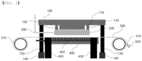
- a compression type dehydrator includes: an upper plate (100) that includes a pressurizing portion (110) and a first guide (120) spaced apart from the pressurizing portion (110) but adjacent to the pressurizing portion (110), and performs a vertical movement by a hydraulic cylinder; a feed plate (200) that includes a hollow portion (210) and a first guide groove (220) surrounding the hollow portion (210) and guiding the vertical movement of the first guide (120), and is positioned on a lower portion of the upper plate (100); a slurry supply line (300) connected to the feed plate (200); a lower plate (400) positioned on a lower portion of the feed plate (200) and having a plurality of holes (410) formed therein; and a filtration belt (500) positioned in close contact with an upper portion of the lower plate (400), characterized in that the compression type dehydrator further comprises a second guide (130) supporting the upper plate (100); an upper plate support (140) having a second guide groove for guiding
- the compression type dehydrator according to the present invention may improve the dehydration performance of the polymer slurry by increasing the pressure for pressurizing the polymer slurry.
- the polymer slurry with the lowest moisture content may be introduced into the drying process, thereby saving energy consumed in the drying process.
- the term “slurry” may refer to a mixture of solid and liquid or a suspension in which fine solid particles are suspended in water
- the term “polymer slurry” may refer to a mixture of a solvent used for polymerization and a solid such as a polymer produced by the polymerization reaction, or a suspension in which the solid is suspended in the solvent.
- slurry cake may refer to a solid after the slurry is dehydrated and filtered.
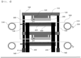
- a compression type dehydrator includes two or more upper plates 100 that includes a pressurizing portion 110 and a first guide 120 spaced apart from the pressurizing portion 110 but adjacent to the pressurizing portion 110, and performs a vertical movement by a hydraulic cylinder (not illustrated); a feed plate 200 that includes a hollow portion 210 and a first guide groove 220 surrounding the hollow portion 210 and guiding the vertical movement of the first guide 120, and is positioned on a lower portion of the upper plate 100; a slurry supply line 300 connected to the feed plate 200; two or more lower plates 400 positioned on a lower portion of the feed plate 200 and having a plurality of holes 410 formed therein; and two or more dehydration means including a filtration belt 500 positioned in close contact with an upper portion of the lower plate 400, wherein the compression type dehydrator further comprises a second guide (130) supporting the upper plate (100); an upper plate support (140) having a second guide groove for guiding a vertical
- a process of producing polymers largely includes polymerization, coagulation, dehydration, and drying processes, and the polymer slurry produced through the polymerization and coagulation processes contains a large amount of moisture.
- the drying process is performed in a manner through heating using a hot air dryer, a fluidized bed dryer, an airflow dryer, an infrared dryer, a dielectric heating dryer, or the like, and in this case, in order to reduce energy consumed, it is a key point to improve the economic efficiency of the process by removing as much moisture from the polymer slurry as possible in the dehydration process prior to subjecting the polymer slurry to the drying process to lower a moisture content.
- a slurry cake in which the moisture has been removed from the polymer slurry in the dehydration process may be obtained as a polymer solid in the form of a powder having a low moisture content by going through the drying process through heating.
- an object of the present invention is to provide a compression type dehydrator capable of reducing energy consumed in the drying process by improving the dehydration performance of the polymer slurry by increasing the pressure for pressurizing the polymer slurry compared to the prior art, and introducing the polymer slurry with the lowest water content.
- the compression type dehydrator includes an upper plate 100 that includes a pressurizing portion 110 and a first guide 120 spaced apart from the pressurizing portion 110 but adjacent to the pressurizing portion 110, and performs a vertical movement by a hydraulic cylinder (not illustrated).
- the pressurizing portion 110 may be positioned on a bottom surface of the upper plate 100 to pressurize a slurry disposed on the lower plate 400 to be described later.
- the pressurizing portion 110 may be positioned at the central portion of the bottom surface of the upper plate 100, but is not limited thereto.
- a pressure transferred to the slurry by a downward movement of the upper plate 100 may be uniform.
- the first guide 120 is positioned on the bottom surface of the upper plate 100, and at the same time, is adjacent to the pressurizing portion 110 and spaced apart from the pressurizing portion 110, and a portion of the first guide 120 may be inserted into and led from the first guide groove 220 included in the feed plate 200 to be described later according to the vertical movement of the upper plate 100.
- the first guide 120 when the upper plate 100 downwardly moves, the first guide 120 may be inserted into the first guide groove 220.
- the first guide 120 inserted into the first guide groove 220 may be led from the first guide groove 220.
- the compression type dehydrator includes a feed plate 200 that includes a hollow portion 210 and a first guide groove 220 surrounding the hollow portion 210 and guiding the vertical movement of the first guide 120, and is positioned on a lower portion of the upper plate 100.
- the feed plate 200 may include a hollow portion 210. According to the downward movement of the upper plate 100, when the feed plate 200 comes into contact with the upper surface of the lower plate 400 to be described later, the hollow portion 210 of the feed plate 200 and an upper portion of the lower plate 400 may form a storing portion (not illustrated) in which the slurry is disposed.
- the first guide groove 220 may guide the vertical movement such that a portion of the first guide 120 is inserted and led.
- the compression type dehydrator includes a slurry supply line 300 connected to the feed plate 200.
- the slurry supply line 300 may serve to supply the slurry from a slurry tank (not illustrated) or a polymer coagulation process portion (not illustrated) separately provided outside the feed plate 200 to the above-described storing portion.
- the compression type dehydrator according to the present invention includes a lower plate 400 positioned on a lower portion of the feed plate 200 and having a plurality of holes 410 formed therein.
- the lower plate 400 includes a plurality of holes 410, so that moisture filtered from the slurry may be introduced into the holes 410.
- the slurry disposed in the storing portion (not illustrated) is compressed by the downward movement of the upper plate 100, filtered moisture may be introduced into the holes 410.
- the compression type dehydrator in order to filter the moisture from the slurry, includes a filtration belt 500 positioned in close contact with the upper portion of the lower plate.
- the filtration belt 500 may include pores having a size through which the moisture may be filtered from the slurry and the filtered moisture may be introduced into the plurality of holes 410 included in the lower plate 400.
- the moisture is filtered from the slurry disposed in the storing portion (not illustrated) through the filtration belt 500, so that a dehydrated slurry cake 600 remains in the storing portion (not illustrated).
- the compression type dehydrator according to the present invention may further include a drain pipe 420 connected to the plurality of holes 410 and discharging the moisture introduced into the holes to the outside, in the lower plate 400.
- the drain pipe 420 may be directly connected to each of all the holes 410 included in the lower plate 400, but is not limited thereto.
- the compression type dehydrator according to the present invention may further include a vacuum device (not illustrated) connected to the drain pipe 420.
- the vacuum device may serve to suck the moisture discharged to the outside of the lower plate 400 through the drain pipe 420. Accordingly, in the process in which the slurry disposed in the storing portion is compressed by the pressurizing portion 110, a suction force by the vacuum device (not illustrated) may also act on the slurry to further improve the dehydration performance.
- the compression type dehydrator according to the present invention further includes the vacuum device (not illustrated), and the drain pipe 420 is directly connected to each of all the holes 410 included in the lower plate 400, the dehydration performance of the slurry may be maximally improved, and accordingly, the slurry cake 600 having the lowest moisture content may be formed.
- the compression type dehydrator according to the present invention may further include a pair of rollers 510 provided in a longitudinal direction of the filtration belt 500.
- the filtration belt 500 may move in the longitudinal direction, and the slurry cake 600 may be transported according to the movement of the filtration belt 500.
- the slurry cake 600 transported according to the movement of the filtration belt 500 may be transported to a separate storage tank (not illustrated) or a drying process portion (not illustrated).
- a separation barrier 520 may be provided on a roller positioned in the direction in which the slurry cake 600 is transported along the longitudinal direction among the pair of rollers 510, and may serve to prevent the slurry cake 600 from being separated from a position to be transported.
- the compression type dehydrator according to the present invention further includes a second guide 130 supporting the upper plate 100; an upper plate support 140 having a second guide groove (not illustrated) for guiding a vertical movement of the second guide 130; and a lower plate support 430 supporting the lower plate 400.
- the second guide 130 supporting the upper plate 100 may perform a vertical movement by a hydraulic cylinder (not illustrated) .
- a portion of the second guide 130 may perform the vertical movement while being inserted into and led from a second guide groove (not illustrated) provided in the upper plate support 140.
- the vertical movement of the upper plate 100 may be performed by the vertical movement of the second guide 130.
- two or more dehydration means are stacked.
- dehydration of a large amount of polymer slurry may be easily performed in the process of producing a polymer solid from a large amount of polymer slurry.
- the second guide 130 may support the two or more upper plates 100, and the lower plate support 430 may support the two or more lower plates 400.
- the second guide 130 may be provided in a coupled form by penetrating through all of the remaining upper plates 100 except for one upper plate 100 positioned at the uppermost portion of the two or more upper plates 100, and may support all of the two or more upper plates 100.
- the lower plate support 430 may be provided in a coupled form by penetrating through all of the remaining lower plates 400 except for one lower plate 400 positioned at the uppermost portion of the two or more lower plates 400, and may support all of the two or more lower plates 400.
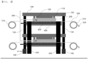
- FIG. 4 is a view illustrating an aspect before an operation of the compression type dehydrator is started.
- an aspect before the operation of the compression type dehydrator is started an aspect before the first guide 120 and the second guide 130 are inserted into the first guide groove 220 and the second guide groove (not illustrated), respectively, may be illustrated.
- the operation of the compression type dehydrator may be performed by a first vertical movement and a second vertical movement of the second guide 130.
- the first guide 120 may not perform the vertical movement, and the bottom surface of the feed plate 200 and the upper surface of the lower plate 400 may be in contact with each other.
- the first guide 120 may pressurize the slurry disposed on the lower plate 400 from the pressurizing portion 110 of the upper plate 100 while performing the downward movement in which the first guide 120 is inserted into the first guide groove 220.
- FIG. 5 is a view illustrating an aspect in which a feed plate 200 and an upper surface of a lower plate 400 come into contact with each other by a first downward movement of a second guide 130.
- the second guide 130 may perform a first downward movement in a height direction of the second guide groove (not illustrated).
- the second guide 130 may perform the first downward movement by a height of 'h1', which is a separation distance between the feed plate 200 and the lower plate 400. That is, the bottom surface of the feed plate 200 and the upper surface of the lower plate 400 may come into contact with each other by the first downward movement of the second guide 130.
- the hollow portion 210 of the feed plate 200 and the upper portion of the lower plate 400 may form the storing portion (not illustrated) in which the slurry is disposed, as described above.
- the slurry may be supplied to and disposed in the storing portion through the slurry supply line 300.
- FIG. 6 is a view illustrating an aspect of pressurizing a slurry from a pressurizing portion 110 through a second downward movement of the second guide 130.
- the second guide 130 may perform a second downward movement in the height direction of the second guide groove (not illustrated).
- the second guide 130 may perform the second downward movement within a height range of 'h2', which is a height of the first guide groove 220, and in this case, the second guide 130 may perform the second downward movement within the height range of 'h2', excluding a height of the slurry cake generated by the pressurization of the slurry disposed in the storing portion (not illustrated). That is, the slurry may be pressurized by the second downward movement of the second guide 130.
- the first guide 120 may perform the second downward movement within the height range of 'h2', which is the height of the first guide groove 220, by the second downward movement of the second guide 130, and in this case, the first guide 120 may perform the second downward movement within the height range of 'h2', excluding a height of the slurry cake generated by the pressurization of the slurry disposed in the storing portion (not illustrated). Accordingly, the slurry disposed in the storing portion (not illustrated) may be pressurized by the pressurizing portion 110 of the upper plate 100.
- the moisture filtered from the slurry may pass through the filtration belt 500 and be introduced into the plurality of holes 410 included in the lower plate 400. Meanwhile, the moisture introduced into the holes 410 may be discharged to the outside of the lower plate 400 through the drain pipe 420.
- the dehydrated slurry cake 600 remains in the storing portion (not illustrated).
- FIG. 7 is a view illustrating an aspect of raising the upper plate 100 and the feed plate 200 through a first upward movement and a second upward movement of the second guide 130.
- the upper plate 100 and the feed plate 200 may be raised through the first upward movement and the second upward movement of the second guide 130. That is, the second guide 130 may perform the upward movement as much as a height of the first downward movement and the second downward movement described above in a height direction of the second guide groove (not illustrated) through the first upward movement and the second upward movement of the second guide 130.
- the upward movement of the second guide 130 described above may be performed in the order of the second upward movement and the first upward movement.
- the second guide 130 may perform the upward movement as much as the height of the second downward movement described above in the height direction of the second guide groove (not illustrated) to raise the upper plate 100 that pressurizes the slurry again.
- the second guide 130 may perform the first upward movement, the second guide 130 may perform the upward movement as much as the height of the first downward movement described above, that is, the height of 'h1' in the height direction of the second guide groove (not illustrated) to raise the feed plate 200 that is in contact with the upper surface of the lower plate 400.
- FIG. 8 is a view illustrating an aspect in which a slurry cake 600 is transported according to a movement of a filtration belt 500 by a roller 510.
- the filtration belt 500 in the state in which the upper plate 100 is raised due to the first upward movement and the second upward movement of the second guide 130, as the filtration belt 500 is wound by at least one of the pair of rollers 510, the filtration belt 500 may move in the longitudinal direction, and the slurry cake 600 may be transported according to the movement of the filtration belt 500. In this way, the slurry cake 600 transported according to the movement of the filtration belt 500 may be transported to a separate storage tank (not illustrated) or a drying process portion (not illustrated).
- a length w1 of a width of a distal end of the first guide 120 may be longer than a length w2 of a width of the first guide groove 220 so that the first guide 120 is not separated from the first guide groove 220 as the first guide 210 performs the upward movement.
- the length w1 of the width of the distal end of the first guide 120 may be longer than the length w2 of the width of the first guide groove 220, and accordingly, it is possible to prevent the first guide 120 from being separated from the first guide groove 220 even though the first guide 120 performs the upward movement by the first upward movement or the second upward movement of the second guide 130.
- a compression type dehydrator in which the dehydration means of FIG. 3 is not stacked may also be operated in the same manner as the operation method of the compression type dehydrator described with reference to FIGS. 4 to 8 .
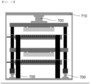
- the vertical movement of the upper plate 100 may be performed by a hydraulic cylinder 700 installed on the upper portion of the upper plate 100, a hydraulic cylinder 700 installed on the lower portion of the second guide 130, or both the hydraulic cylinders, but is not limited thereto.
- the compression type dehydrator according to the present invention may further include a frame 710 for fixing the hydraulic cylinder 700 installed on the upper portion of the upper plate 100 without interfering with the operation of all components included in the compression type dehydrator.
- a portion of the first guide 120 may be inserted into and led from the first guide groove 220 included in the feed plate 200 by the vertical movement of the lower plate 400, that is, the lower plate support 430.
- the vertical movement of the lower plate support 430 may be performed by the hydraulic cylinder 700 installed on the lower portion of the lower plate support 430, but is not limited thereto.
- the upper plate support 140 for guiding the vertical movement of the second guide may not be included.
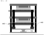
- the compression type dehydrator when the compression type dehydrator performs the vertical movement of the lower plate 400, that is, the lower plate support 430, the compression type dehydrator may further include a first support 440 provided with a third guide groove (not illustrated) for guiding the vertical movement of the lower plate support 430, and the vertical movement of the lower plate 400 may be performed while a portion of the lower plate support 430 is inserted into and led from a third guide groove (not illustrated) included in the first support 440.
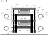
- FIGS. 4 to 8 illustrate only the views according to the embodiment in which the vertical movements of the two or more upper plates 100 are simultaneously performed by the vertical movement of the second guide 130 while the lower plate support 430 is fixed without performing the vertical movement, but as illustrated in FIG. 11 , another embodiment in which the vertical movements of the two or more lower plates 400 are simultaneously performed by the vertical movement of the lower plate support 430 while the second guide 130 is fixed without performing the vertical movement may also be included in the present invention.
- an operation of the compression type dehydrator according to an aspect illustrated in FIG. 11 may be performed by a first vertical movement and a second vertical movement of the lower plate support 430.
- the first guide 120 may not perform the vertical movement, and the bottom surface of the feed plate 200 and the upper surface of the lower plate 400 may be in contact with each other.
- the first guide 120 may pressurize the slurry disposed on the lower plate 400 from the pressurizing portion 110 of the upper plate 100 while being inserted into the first guide groove 220.
- the hydraulic cylinder illustrated in FIGS. 10 and 11 may perform an operation while hydraulic pressure is applied thereto when the second guide 130 or the lower plate support 430 performs the upward movement, and the hydraulic pressure is released therefrom when the second guide 130 or the lower plate support 430 performs the downward movement.
- the upper plate 100, the feed plate 200, and the lower plate 400 may be made of one or more selected from the group consisting of titanium, tungsten, bronze, carbon steel for mechanical structure, stainless steel, and nickel-chromium steel.
- the upper plate 100, the feed plate 200, and the lower plate 400 made of the above-described materials may not be deformed or damaged by pressure, and are not limited only to the types of the above-described materials.
- the slurry may be a polymer slurry produced by a polymerization reaction.
- the compression type dehydrator according to the present invention has the effect of reducing the energy consumed in the drying process by maximally lowering the moisture content of the polymer slurry in the dehydration process prior to the drying process in the process for producing the polymer solid.
- the polymer slurry may be an acrylonitrile-butadiene-styrene polymer slurry (ABS) or a methacrylate-butadiene-styrene polymer slurry (MBS), and in this case, the dehydration performance of the ABS or MBS polymer slurry by the compression type dehydrator according to the present invention may be excellent.
- ABS acrylonitrile-butadiene-styrene polymer slurry
- MBS methacrylate-butadiene-styrene polymer slurry
Landscapes
- Engineering & Computer Science (AREA)
- Mechanical Engineering (AREA)
- Chemical & Material Sciences (AREA)
- Health & Medical Sciences (AREA)
- Chemical Kinetics & Catalysis (AREA)
- Medicinal Chemistry (AREA)
- Polymers & Plastics (AREA)
- Organic Chemistry (AREA)
- Life Sciences & Earth Sciences (AREA)
- Molecular Biology (AREA)
- General Engineering & Computer Science (AREA)
- Treatment Of Sludge (AREA)
Claims (7)
- Kompressions-Dehydrator, umfassend:eine obere Platte (100), die einen Druckbeaufschlagungsabschnitt (110) und eine erste Führung (120) aufweist, die von dem Druckbeaufschlagungsabschnitt (110) beabstandet ist, aber an den Druckbeaufschlagungsabschnitt (110) angrenzt, und eine vertikale Bewegung durch einen Hydraulikzylinder ausführt;eine Zuführplatte (200), die einen hohlen Abschnitt (210) und eine erste Führungsnut (220) aufweist, die den hohlen Abschnitt (210) umgibt und die vertikale Bewegung der ersten Führung (120) führt, und die an einem unteren Abschnitt der oberen Platte (100) positioniert ist;eine Aufschlämmungszufuhrleitung (300), die mit der Zuführplatte (200) verbunden ist;eine untere Platte (400), die an einem unteren Abschnitt der Zuführplatte (200) positioniert ist und eine Vielzahl von darin ausgebildeten Löchern (410) aufweist; und ein Entwässerungsmittel umfassendein Filterband (500), das in engem Kontakt mit einem oberen Abschnitt der unteren Platte (400) positioniert ist,dadurch gekennzeichnet, dass der Kompressions-Dehydrator ferner eine zweite Führung (130) umfasst, die die obere Platte (100) stützt;eine obere Plattenstütze (140), die eine zweite Führungsnut zum Führen einer vertikalen Bewegung der zweiten Führung (130) aufweist; undeine untere Plattenstütze (430), die die untere Platte (400) stützt;wobei der Kompressions-Dehydrator ferner zwei oder mehr Entwässerungsmittel, zwei oder mehr obere Platten (100) und zwei oder mehr untere Platten (400) umfasst, wobei zwei oder mehr Entwässerungsmittel gestapelt sind;die zweite Führung (130) die zwei oder mehr oberen Platten (100) stützt, unddie untere Plattenstütze (430) die zwei oder mehr unteren Platten (400) stützt; undvertikale Bewegungen der zwei oder mehr oberen Platten (100) gleichzeitig durch eine vertikale Bewegung der zweiten Führung (130) ausgeführt werden.
- Kompressions-Dehydrator nach Anspruch 1, bei dem eine Aufschlämmung in dem oberen Abschnitt der unteren Platte (400) und dem hohlen Abschnitt (210) der Zuführplatte (200) durch die Aufschlämmungszufuhrleitung verteilt ist, und
gefilterte Feuchtigkeit in die Löcher (410) der unteren Platte (400) eingebracht wird, während die verteilte Aufschlämmung durch eine Abwärtsbewegung der oberen Platte (100) komprimiert wird. - Kompressions-Dehydrator nach Anspruch 2, ferner umfassend ein Ablaufrohr (420), das mit der Vielzahl von Löchern (410) verbunden ist und die in die Löcher (410) der unteren Platte (400) eingebrachte Feuchtigkeit nach außen abführt.
- Kompressions-Dehydrator nach Anspruch 1, ferner umfassend ein Paar von Walzen (510), die in einer Längsrichtung des Filterbands (500) vorgesehen sind.
- Kompressions-Dehydrator nach Anspruch 4, bei dem sich das Filterband (500) durch das mindestens eine Paar von Walzen (510) in der Längsrichtung bewegt und ein Aufschlämmungskuchen gemäß der Bewegung des Filterbands (500) transportiert wird.
- Kompressions-Dehydrator nach Anspruch 1, bei dem die obere Platte (100), die Zuführplatte (200) und die untere Platte (400) aus einem oder mehreren hergestellt sind, die aus der Gruppe ausgewählt sind, die aus Titan, Wolfram, Bronze, Kohlenstoffstahl für mechanische Strukturen, rostfreiem Stahl und Nickel-Chrom-Stahl besteht.
- Kompressions-Dehydrator nach Anspruch 1, bei dem die Aufschlämmung eine Polymeraufschlämmung ist, die durch eine Polymerisationsreaktion hergestellt wird.
Applications Claiming Priority (2)
| Application Number | Priority Date | Filing Date | Title |
|---|---|---|---|
| KR1020200124724A KR102795458B1 (ko) | 2020-09-25 | 2020-09-25 | 압축식 탈수기 |
| PCT/KR2021/008783 WO2022065644A1 (ko) | 2020-09-25 | 2021-07-09 | 압축식 탈수기 |
Publications (3)
| Publication Number | Publication Date |
|---|---|
| EP4008733A1 EP4008733A1 (de) | 2022-06-08 |
| EP4008733A4 EP4008733A4 (de) | 2023-10-18 |
| EP4008733B1 true EP4008733B1 (de) | 2024-08-28 |
Family
ID=80846753
Family Applications (1)
| Application Number | Title | Priority Date | Filing Date |
|---|---|---|---|
| EP21835924.8A Active EP4008733B1 (de) | 2020-09-25 | 2021-07-09 | Verdichtungstrockner |
Country Status (5)
| Country | Link |
|---|---|
| US (1) | US12122117B2 (de) |
| EP (1) | EP4008733B1 (de) |
| KR (1) | KR102795458B1 (de) |
| CN (1) | CN114568020B (de) |
| WO (1) | WO2022065644A1 (de) |
Family Cites Families (22)
| Publication number | Priority date | Publication date | Assignee | Title |
|---|---|---|---|---|
| US4346003A (en) | 1980-11-03 | 1982-08-24 | Polyakov Nikolai F | Mash-separating filter-press |
| ATE78414T1 (de) | 1985-11-14 | 1992-08-15 | Kuebler Hans Hakue Filter | Filterpresse fuer die flussigkeitsabtrennung aus schlaemmen bis auf einen hohen feststoff-gehalt. |
| DE3734974A1 (de) * | 1986-10-21 | 1989-04-20 | Baehr Albert | Vorrichtung zum entwaessern von schlamm und aehnlichen substanzen |
| NO901889L (no) * | 1989-05-10 | 1990-11-12 | Albert Baehr | Fremgangsmaate ved og kammerfilterpresse for avvanning av slam og lignende substanser. |
| US5386768A (en) * | 1993-03-26 | 1995-02-07 | Roediger Pittsburgh, Inc. | Apparatus for dewatering sludge |
| JPH0724402U (ja) | 1993-10-07 | 1995-05-09 | 株式会社トーア | スラッジ脱水濾過装置 |
| EP0714687B1 (de) | 1994-12-01 | 1999-04-07 | Albert Bähr | Verfahren und Vorrichtung zum Entwässern von Schlämmen und ähnlichen Substanzen |
| DE102008047427A1 (de) * | 2008-09-15 | 2010-04-15 | Bähr, Albert, Dipl.-Ing. | Verfahren und Vorrichtung zur Fest-Flüssig-Trennung von Stoffgemischen und Suspensionen |
| CN101745260B (zh) * | 2008-12-11 | 2011-11-30 | 张民良 | 快速超大处理规模的柔韧管压榨固液分离装置 |
| KR100946262B1 (ko) | 2009-05-11 | 2010-03-08 | (주)동일캔바스엔지니어링 | 고온가압식 슬러지 감량장치 |
| US20120223021A1 (en) | 2011-03-03 | 2012-09-06 | Rathallaigh Dominic O | System and method for treating waste |
| KR101332031B1 (ko) * | 2011-05-13 | 2013-11-22 | 강석웅 | 슬러지 탈수용 타워 필터프레스 장치 |
| KR101332037B1 (ko) | 2011-12-16 | 2013-11-22 | 엘지이노텍 주식회사 | 적층 로터 코어 및 이를 구비한 모터 |
| KR20130131606A (ko) * | 2012-05-24 | 2013-12-04 | 강석웅 | 슬러지 탈수세트 및 복수의 층을 가진 슬러지 탈수장치 |
| JP5922536B2 (ja) | 2012-09-10 | 2016-05-24 | 三菱重工業株式会社 | 非鉄・金属類以外のpcb汚染物質の処理装置 |
| KR101245134B1 (ko) | 2012-10-30 | 2013-04-02 | 한붕전 | 하수 맨홀 준설차의 슬러지 처리방법 |
| KR101345389B1 (ko) * | 2013-10-08 | 2013-12-24 | 녹스 코리아(주) | 수처리용 탈수장치 |
| CN104743695B (zh) * | 2014-11-26 | 2017-05-17 | 蒋子厚 | 一种改进的椭叠固液分离设备 |
| CN104722107A (zh) | 2015-03-23 | 2015-06-24 | 宜兴广大污泥处置利用技术有限公司 | 一种立式板框污泥脱水机 |
| CN204522421U (zh) | 2015-03-23 | 2015-08-05 | 宜兴广大污泥处置利用技术有限公司 | 一种立式板框污泥脱水机 |
| KR20170047038A (ko) * | 2015-10-22 | 2017-05-04 | 황명회 | 케이크 탈리 구조를 갖는 필터프레스 |
| CN107352775A (zh) * | 2017-08-23 | 2017-11-17 | 安尼康(福建)环保设备有限公司 | 一种尾端进泥的叠片螺旋式脱水机 |
-
2020
- 2020-09-25 KR KR1020200124724A patent/KR102795458B1/ko active Active
-
2021
- 2021-07-09 WO PCT/KR2021/008783 patent/WO2022065644A1/ko not_active Ceased
- 2021-07-09 CN CN202180004704.4A patent/CN114568020B/zh active Active
- 2021-07-09 EP EP21835924.8A patent/EP4008733B1/de active Active
- 2021-07-09 US US17/628,020 patent/US12122117B2/en active Active
Also Published As
| Publication number | Publication date |
|---|---|
| EP4008733A1 (de) | 2022-06-08 |
| KR102795458B1 (ko) | 2025-04-11 |
| WO2022065644A1 (ko) | 2022-03-31 |
| EP4008733A4 (de) | 2023-10-18 |
| KR20220041476A (ko) | 2022-04-01 |
| CN114568020B (zh) | 2024-09-06 |
| CN114568020A (zh) | 2022-05-31 |
| US20220402229A1 (en) | 2022-12-22 |
| US12122117B2 (en) | 2024-10-22 |
Similar Documents
| Publication | Publication Date | Title |
|---|---|---|
| US8440082B2 (en) | Method and apparatus for the solid-liquid-separation of material mixtures and suspensions | |
| CN112607995B (zh) | 一种污泥连续脱水系统 | |
| CN208454757U (zh) | 一种印染废水和污泥处理系统 | |
| CN210340655U (zh) | 一种用于污泥脱水的动态密封全方位出水的压榨装置 | |
| EP4008733B1 (de) | Verdichtungstrockner | |
| CN210736501U (zh) | 一种连续深度脱水设备 | |
| CN114804572B (zh) | 一种具有分布式压榨单元的污泥压榨机 | |
| US20150021280A1 (en) | Materials handling and treatment | |
| JP6484363B2 (ja) | フィルタプレス脱水装置及びフィルタプレス脱水装置の運転方法 | |
| CN213885127U (zh) | 一种高效压滤脱水装置 | |
| CN213416628U (zh) | 一种连续梯级高压脱水系统 | |
| EP2623438B1 (de) | Materialhandhabung und -Behandlung | |
| CN214188582U (zh) | 双上料的压榨脱水机 | |
| CN108640470A (zh) | 高效污泥压榨机 | |
| CN110665265A (zh) | 多功能压滤机 | |
| CN115140916A (zh) | 一种深度压榨脱水设备 | |
| KR20130018279A (ko) | 고체 액체 분리 방법 | |
| AU723824B2 (en) | Filtration system for removing solid particles | |
| CN118702385B (zh) | 一种自适应多层压滤系统和方法 | |
| CN112110631A (zh) | 一种连续梯级高压脱水系统 | |
| CN223134312U (zh) | 一种耦合式高强度脱水装置 | |
| CN221061858U (zh) | 板框式隔膜压滤机 | |
| CN215085244U (zh) | 立式脱水设备 | |
| WO2003057344A1 (en) | Method and apparatus for controlling the forming of a cake in a filter press | |
| CN114425188A (zh) | 一种压滤器、含有该压滤器的脱水机及一种压滤脱水机组 |
Legal Events
| Date | Code | Title | Description |
|---|---|---|---|
| STAA | Information on the status of an ep patent application or granted ep patent |
Free format text: STATUS: UNKNOWN |
|
| STAA | Information on the status of an ep patent application or granted ep patent |
Free format text: STATUS: THE INTERNATIONAL PUBLICATION HAS BEEN MADE |
|
| PUAI | Public reference made under article 153(3) epc to a published international application that has entered the european phase |
Free format text: ORIGINAL CODE: 0009012 |
|
| STAA | Information on the status of an ep patent application or granted ep patent |
Free format text: STATUS: REQUEST FOR EXAMINATION WAS MADE |
|
| 17P | Request for examination filed |
Effective date: 20220113 |
|
| AK | Designated contracting states |
Kind code of ref document: A1 Designated state(s): AL AT BE BG CH CY CZ DE DK EE ES FI FR GB GR HR HU IE IS IT LI LT LU LV MC MK MT NL NO PL PT RO RS SE SI SK SM TR |
|
| REG | Reference to a national code |
Ref country code: DE Ref legal event code: R079 Free format text: PREVIOUS MAIN CLASS: C08F0006000000 Ipc: F26B0005140000 Ref document number: 602021018091 Country of ref document: DE |
|
| A4 | Supplementary search report drawn up and despatched |
Effective date: 20230920 |
|
| RIC1 | Information provided on ipc code assigned before grant |
Ipc: B30B 7/02 20060101ALI20230914BHEP Ipc: B30B 9/26 20060101ALI20230914BHEP Ipc: B30B 9/06 20060101ALI20230914BHEP Ipc: C08F 6/00 20060101ALI20230914BHEP Ipc: F26B 5/14 20060101AFI20230914BHEP |
|
| DAV | Request for validation of the european patent (deleted) | ||
| DAX | Request for extension of the european patent (deleted) | ||
| GRAP | Despatch of communication of intention to grant a patent |
Free format text: ORIGINAL CODE: EPIDOSNIGR1 |
|
| STAA | Information on the status of an ep patent application or granted ep patent |
Free format text: STATUS: GRANT OF PATENT IS INTENDED |
|
| INTG | Intention to grant announced |
Effective date: 20240605 |
|
| GRAS | Grant fee paid |
Free format text: ORIGINAL CODE: EPIDOSNIGR3 |
|
| GRAA | (expected) grant |
Free format text: ORIGINAL CODE: 0009210 |
|
| STAA | Information on the status of an ep patent application or granted ep patent |
Free format text: STATUS: THE PATENT HAS BEEN GRANTED |
|
| AK | Designated contracting states |
Kind code of ref document: B1 Designated state(s): AL AT BE BG CH CY CZ DE DK EE ES FI FR GB GR HR HU IE IS IT LI LT LU LV MC MK MT NL NO PL PT RO RS SE SI SK SM TR |
|
| REG | Reference to a national code |
Ref country code: CH Ref legal event code: EP |
|
| REG | Reference to a national code |
Ref country code: DE Ref legal event code: R096 Ref document number: 602021018091 Country of ref document: DE |
|
| REG | Reference to a national code |
Ref country code: IE Ref legal event code: FG4D |
|
| REG | Reference to a national code |
Ref country code: LT Ref legal event code: MG9D |
|
| PG25 | Lapsed in a contracting state [announced via postgrant information from national office to epo] |
Ref country code: NO Free format text: LAPSE BECAUSE OF FAILURE TO SUBMIT A TRANSLATION OF THE DESCRIPTION OR TO PAY THE FEE WITHIN THE PRESCRIBED TIME-LIMIT Effective date: 20241128 |
|
| REG | Reference to a national code |
Ref country code: AT Ref legal event code: MK05 Ref document number: 1718351 Country of ref document: AT Kind code of ref document: T Effective date: 20240828 |
|
| PG25 | Lapsed in a contracting state [announced via postgrant information from national office to epo] |
Ref country code: NL Free format text: LAPSE BECAUSE OF FAILURE TO SUBMIT A TRANSLATION OF THE DESCRIPTION OR TO PAY THE FEE WITHIN THE PRESCRIBED TIME-LIMIT Effective date: 20240828 Ref country code: PT Free format text: LAPSE BECAUSE OF FAILURE TO SUBMIT A TRANSLATION OF THE DESCRIPTION OR TO PAY THE FEE WITHIN THE PRESCRIBED TIME-LIMIT Effective date: 20241230 Ref country code: GR Free format text: LAPSE BECAUSE OF FAILURE TO SUBMIT A TRANSLATION OF THE DESCRIPTION OR TO PAY THE FEE WITHIN THE PRESCRIBED TIME-LIMIT Effective date: 20241129 Ref country code: PL Free format text: LAPSE BECAUSE OF FAILURE TO SUBMIT A TRANSLATION OF THE DESCRIPTION OR TO PAY THE FEE WITHIN THE PRESCRIBED TIME-LIMIT Effective date: 20240828 Ref country code: FI Free format text: LAPSE BECAUSE OF FAILURE TO SUBMIT A TRANSLATION OF THE DESCRIPTION OR TO PAY THE FEE WITHIN THE PRESCRIBED TIME-LIMIT Effective date: 20240828 |
|
| PG25 | Lapsed in a contracting state [announced via postgrant information from national office to epo] |
Ref country code: BG Free format text: LAPSE BECAUSE OF FAILURE TO SUBMIT A TRANSLATION OF THE DESCRIPTION OR TO PAY THE FEE WITHIN THE PRESCRIBED TIME-LIMIT Effective date: 20240828 |
|
| PG25 | Lapsed in a contracting state [announced via postgrant information from national office to epo] |
Ref country code: LV Free format text: LAPSE BECAUSE OF FAILURE TO SUBMIT A TRANSLATION OF THE DESCRIPTION OR TO PAY THE FEE WITHIN THE PRESCRIBED TIME-LIMIT Effective date: 20240828 |
|
| REG | Reference to a national code |
Ref country code: NL Ref legal event code: MP Effective date: 20240828 |
|
| PG25 | Lapsed in a contracting state [announced via postgrant information from national office to epo] |
Ref country code: IS Free format text: LAPSE BECAUSE OF FAILURE TO SUBMIT A TRANSLATION OF THE DESCRIPTION OR TO PAY THE FEE WITHIN THE PRESCRIBED TIME-LIMIT Effective date: 20241228 Ref country code: AT Free format text: LAPSE BECAUSE OF FAILURE TO SUBMIT A TRANSLATION OF THE DESCRIPTION OR TO PAY THE FEE WITHIN THE PRESCRIBED TIME-LIMIT Effective date: 20240828 |
|
| PG25 | Lapsed in a contracting state [announced via postgrant information from national office to epo] |
Ref country code: HR Free format text: LAPSE BECAUSE OF FAILURE TO SUBMIT A TRANSLATION OF THE DESCRIPTION OR TO PAY THE FEE WITHIN THE PRESCRIBED TIME-LIMIT Effective date: 20240828 |
|
| PG25 | Lapsed in a contracting state [announced via postgrant information from national office to epo] |
Ref country code: RS Free format text: LAPSE BECAUSE OF FAILURE TO SUBMIT A TRANSLATION OF THE DESCRIPTION OR TO PAY THE FEE WITHIN THE PRESCRIBED TIME-LIMIT Effective date: 20241128 Ref country code: ES Free format text: LAPSE BECAUSE OF FAILURE TO SUBMIT A TRANSLATION OF THE DESCRIPTION OR TO PAY THE FEE WITHIN THE PRESCRIBED TIME-LIMIT Effective date: 20240828 |
|
| PG25 | Lapsed in a contracting state [announced via postgrant information from national office to epo] |
Ref country code: RS Free format text: LAPSE BECAUSE OF FAILURE TO SUBMIT A TRANSLATION OF THE DESCRIPTION OR TO PAY THE FEE WITHIN THE PRESCRIBED TIME-LIMIT Effective date: 20241128 Ref country code: PT Free format text: LAPSE BECAUSE OF FAILURE TO SUBMIT A TRANSLATION OF THE DESCRIPTION OR TO PAY THE FEE WITHIN THE PRESCRIBED TIME-LIMIT Effective date: 20241230 Ref country code: PL Free format text: LAPSE BECAUSE OF FAILURE TO SUBMIT A TRANSLATION OF THE DESCRIPTION OR TO PAY THE FEE WITHIN THE PRESCRIBED TIME-LIMIT Effective date: 20240828 Ref country code: NO Free format text: LAPSE BECAUSE OF FAILURE TO SUBMIT A TRANSLATION OF THE DESCRIPTION OR TO PAY THE FEE WITHIN THE PRESCRIBED TIME-LIMIT Effective date: 20241128 Ref country code: NL Free format text: LAPSE BECAUSE OF FAILURE TO SUBMIT A TRANSLATION OF THE DESCRIPTION OR TO PAY THE FEE WITHIN THE PRESCRIBED TIME-LIMIT Effective date: 20240828 Ref country code: LV Free format text: LAPSE BECAUSE OF FAILURE TO SUBMIT A TRANSLATION OF THE DESCRIPTION OR TO PAY THE FEE WITHIN THE PRESCRIBED TIME-LIMIT Effective date: 20240828 Ref country code: IS Free format text: LAPSE BECAUSE OF FAILURE TO SUBMIT A TRANSLATION OF THE DESCRIPTION OR TO PAY THE FEE WITHIN THE PRESCRIBED TIME-LIMIT Effective date: 20241228 Ref country code: HR Free format text: LAPSE BECAUSE OF FAILURE TO SUBMIT A TRANSLATION OF THE DESCRIPTION OR TO PAY THE FEE WITHIN THE PRESCRIBED TIME-LIMIT Effective date: 20240828 Ref country code: GR Free format text: LAPSE BECAUSE OF FAILURE TO SUBMIT A TRANSLATION OF THE DESCRIPTION OR TO PAY THE FEE WITHIN THE PRESCRIBED TIME-LIMIT Effective date: 20241129 Ref country code: FI Free format text: LAPSE BECAUSE OF FAILURE TO SUBMIT A TRANSLATION OF THE DESCRIPTION OR TO PAY THE FEE WITHIN THE PRESCRIBED TIME-LIMIT Effective date: 20240828 Ref country code: ES Free format text: LAPSE BECAUSE OF FAILURE TO SUBMIT A TRANSLATION OF THE DESCRIPTION OR TO PAY THE FEE WITHIN THE PRESCRIBED TIME-LIMIT Effective date: 20240828 Ref country code: BG Free format text: LAPSE BECAUSE OF FAILURE TO SUBMIT A TRANSLATION OF THE DESCRIPTION OR TO PAY THE FEE WITHIN THE PRESCRIBED TIME-LIMIT Effective date: 20240828 Ref country code: AT Free format text: LAPSE BECAUSE OF FAILURE TO SUBMIT A TRANSLATION OF THE DESCRIPTION OR TO PAY THE FEE WITHIN THE PRESCRIBED TIME-LIMIT Effective date: 20240828 |
|
| PG25 | Lapsed in a contracting state [announced via postgrant information from national office to epo] |
Ref country code: SM Free format text: LAPSE BECAUSE OF FAILURE TO SUBMIT A TRANSLATION OF THE DESCRIPTION OR TO PAY THE FEE WITHIN THE PRESCRIBED TIME-LIMIT Effective date: 20240828 Ref country code: RO Free format text: LAPSE BECAUSE OF FAILURE TO SUBMIT A TRANSLATION OF THE DESCRIPTION OR TO PAY THE FEE WITHIN THE PRESCRIBED TIME-LIMIT Effective date: 20240828 Ref country code: DK Free format text: LAPSE BECAUSE OF FAILURE TO SUBMIT A TRANSLATION OF THE DESCRIPTION OR TO PAY THE FEE WITHIN THE PRESCRIBED TIME-LIMIT Effective date: 20240828 |
|
| PG25 | Lapsed in a contracting state [announced via postgrant information from national office to epo] |
Ref country code: EE Free format text: LAPSE BECAUSE OF FAILURE TO SUBMIT A TRANSLATION OF THE DESCRIPTION OR TO PAY THE FEE WITHIN THE PRESCRIBED TIME-LIMIT Effective date: 20240828 |
|
| PG25 | Lapsed in a contracting state [announced via postgrant information from national office to epo] |
Ref country code: CZ Free format text: LAPSE BECAUSE OF FAILURE TO SUBMIT A TRANSLATION OF THE DESCRIPTION OR TO PAY THE FEE WITHIN THE PRESCRIBED TIME-LIMIT Effective date: 20240828 |
|
| PG25 | Lapsed in a contracting state [announced via postgrant information from national office to epo] |
Ref country code: SK Free format text: LAPSE BECAUSE OF FAILURE TO SUBMIT A TRANSLATION OF THE DESCRIPTION OR TO PAY THE FEE WITHIN THE PRESCRIBED TIME-LIMIT Effective date: 20240828 Ref country code: IT Free format text: LAPSE BECAUSE OF FAILURE TO SUBMIT A TRANSLATION OF THE DESCRIPTION OR TO PAY THE FEE WITHIN THE PRESCRIBED TIME-LIMIT Effective date: 20240828 |
|
| REG | Reference to a national code |
Ref country code: DE Ref legal event code: R097 Ref document number: 602021018091 Country of ref document: DE |
|
| PLBE | No opposition filed within time limit |
Free format text: ORIGINAL CODE: 0009261 |
|
| STAA | Information on the status of an ep patent application or granted ep patent |
Free format text: STATUS: NO OPPOSITION FILED WITHIN TIME LIMIT |
|
| PGFP | Annual fee paid to national office [announced via postgrant information from national office to epo] |
Ref country code: GB Payment date: 20250624 Year of fee payment: 5 |
|
| PGFP | Annual fee paid to national office [announced via postgrant information from national office to epo] |
Ref country code: FR Payment date: 20250624 Year of fee payment: 5 |
|
| 26N | No opposition filed |
Effective date: 20250530 |
|
| PG25 | Lapsed in a contracting state [announced via postgrant information from national office to epo] |
Ref country code: SE Free format text: LAPSE BECAUSE OF FAILURE TO SUBMIT A TRANSLATION OF THE DESCRIPTION OR TO PAY THE FEE WITHIN THE PRESCRIBED TIME-LIMIT Effective date: 20240828 |
|
| PGFP | Annual fee paid to national office [announced via postgrant information from national office to epo] |
Ref country code: DE Payment date: 20250624 Year of fee payment: 5 |
|
| REG | Reference to a national code |
Ref country code: CH Ref legal event code: H13 Free format text: ST27 STATUS EVENT CODE: U-0-0-H10-H13 (AS PROVIDED BY THE NATIONAL OFFICE) Effective date: 20260224 |
|
| PG25 | Lapsed in a contracting state [announced via postgrant information from national office to epo] |
Ref country code: LU Free format text: LAPSE BECAUSE OF NON-PAYMENT OF DUE FEES Effective date: 20250709 |