EP4135869B1 - Dichtungsstreifen zum abdichten benachbarter filterplattenanordnungen einer filterpresse, wie turmpresse, filterrahmen, filterrahmenanordnung und filtervorrichtung - Google Patents
Dichtungsstreifen zum abdichten benachbarter filterplattenanordnungen einer filterpresse, wie turmpresse, filterrahmen, filterrahmenanordnung und filtervorrichtung Download PDFInfo
- Publication number
- EP4135869B1 EP4135869B1 EP20931222.2A EP20931222A EP4135869B1 EP 4135869 B1 EP4135869 B1 EP 4135869B1 EP 20931222 A EP20931222 A EP 20931222A EP 4135869 B1 EP4135869 B1 EP 4135869B1
- Authority
- EP
- European Patent Office
- Prior art keywords
- sealing strip
- filter
- cross
- filter frame
- stiffener
- Prior art date
- Legal status (The legal status is an assumption and is not a legal conclusion. Google has not performed a legal analysis and makes no representation as to the accuracy of the status listed.)
- Active
Links
Images

Classifications
-
- F—MECHANICAL ENGINEERING; LIGHTING; HEATING; WEAPONS; BLASTING
- F16—ENGINEERING ELEMENTS AND UNITS; GENERAL MEASURES FOR PRODUCING AND MAINTAINING EFFECTIVE FUNCTIONING OF MACHINES OR INSTALLATIONS; THERMAL INSULATION IN GENERAL
- F16J—PISTONS; CYLINDERS; SEALINGS
- F16J15/00—Sealings
- F16J15/02—Sealings between relatively-stationary surfaces
- F16J15/06—Sealings between relatively-stationary surfaces with solid packing compressed between sealing surfaces
- F16J15/10—Sealings between relatively-stationary surfaces with solid packing compressed between sealing surfaces with non-metallic packing
- F16J15/104—Sealings between relatively-stationary surfaces with solid packing compressed between sealing surfaces with non-metallic packing characterised by structure
-
- B—PERFORMING OPERATIONS; TRANSPORTING
- B01—PHYSICAL OR CHEMICAL PROCESSES OR APPARATUS IN GENERAL
- B01D—SEPARATION
- B01D25/00—Filters formed by clamping together several filtering elements or parts of such elements
- B01D25/12—Filter presses, i.e. of the plate or plate and frame type
- B01D25/164—Chamber-plate presses, i.e. the sides of the filtering elements being clamped between two successive filtering plates
- B01D25/1645—Chamber-plate presses, i.e. the sides of the filtering elements being clamped between two successive filtering plates the plates being placed in a non-vertical position
-
- B—PERFORMING OPERATIONS; TRANSPORTING
- B01—PHYSICAL OR CHEMICAL PROCESSES OR APPARATUS IN GENERAL
- B01D—SEPARATION
- B01D25/00—Filters formed by clamping together several filtering elements or parts of such elements
- B01D25/12—Filter presses, i.e. of the plate or plate and frame type
- B01D25/164—Chamber-plate presses, i.e. the sides of the filtering elements being clamped between two successive filtering plates
-
- B—PERFORMING OPERATIONS; TRANSPORTING
- B01—PHYSICAL OR CHEMICAL PROCESSES OR APPARATUS IN GENERAL
- B01D—SEPARATION
- B01D25/00—Filters formed by clamping together several filtering elements or parts of such elements
- B01D25/12—Filter presses, i.e. of the plate or plate and frame type
- B01D25/21—Plate and frame presses
- B01D25/215—Construction of the filter plates, frames
-
- F—MECHANICAL ENGINEERING; LIGHTING; HEATING; WEAPONS; BLASTING
- F16—ENGINEERING ELEMENTS AND UNITS; GENERAL MEASURES FOR PRODUCING AND MAINTAINING EFFECTIVE FUNCTIONING OF MACHINES OR INSTALLATIONS; THERMAL INSULATION IN GENERAL
- F16J—PISTONS; CYLINDERS; SEALINGS
- F16J15/00—Sealings
- F16J15/02—Sealings between relatively-stationary surfaces
- F16J15/06—Sealings between relatively-stationary surfaces with solid packing compressed between sealing surfaces
- F16J15/10—Sealings between relatively-stationary surfaces with solid packing compressed between sealing surfaces with non-metallic packing
- F16J15/12—Sealings between relatively-stationary surfaces with solid packing compressed between sealing surfaces with non-metallic packing with metal reinforcement or covering
- F16J15/121—Sealings between relatively-stationary surfaces with solid packing compressed between sealing surfaces with non-metallic packing with metal reinforcement or covering with metal reinforcement
- F16J15/122—Sealings between relatively-stationary surfaces with solid packing compressed between sealing surfaces with non-metallic packing with metal reinforcement or covering with metal reinforcement generally parallel to the surfaces
-
- B—PERFORMING OPERATIONS; TRANSPORTING
- B01—PHYSICAL OR CHEMICAL PROCESSES OR APPARATUS IN GENERAL
- B01D—SEPARATION
- B01D2201/00—Details relating to filtering apparatus
- B01D2201/34—Seals or gaskets for filtering elements
-
- B—PERFORMING OPERATIONS; TRANSPORTING
- B01—PHYSICAL OR CHEMICAL PROCESSES OR APPARATUS IN GENERAL
- B01D—SEPARATION
- B01D2201/00—Details relating to filtering apparatus
- B01D2201/34—Seals or gaskets for filtering elements
- B01D2201/342—Axial sealings
Definitions
- the present disclosure relates to filter presses, such as horizontal filter presses, e.g. tower presses, and more particularly to sealing strips used in such filter presses for sealing the interface between adjacent filter frame assemblies, between which a filter chamber is formed.
- the present disclosure further concerns a filter frame, a filter frame assembly and a horizontal filter press apparatus, such as a tower press.
- a sealing strip has conventionally been used for sealing the interface between two adjacent filter frame assemblies, in between which a filter chamber is formed.
- a filter frame assembly may be formed by a frame-and-plate assembly, or a recessed plate incorporating the frame and plate portions.
- the sealing strip must be able seal the filtration pressure prevailing in the filter chamber against the environmental pressure, in addition to withstand the compression pressure at which the adjacent filter frame assemblies are pressed against each other. Due to the repetitive compression cycles and the often abrasive nature of the slurry being filtered, the sealing strip is a wear part which must be replace periodically.
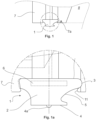
- the sealing strip 1 comprises an elongate body 2 extending along a length direction and having a first longitudinal lend 1a and second longitudinal end 1b.
- the intermediate portion 5 has a width W5, defined along a lateral direction transverse and coplanar to the length direction, less than that W3 of the base portion 3.
- W5 the width of the sealing strip 1, as seen along the longitudinal direction, is more narrow at the intermediate portion 5 than at the base portion 3.
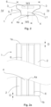
- stiffener 6 is encapsulated by the body 2 of the sealing strip 1.
- the stiffener 6 is longitudinally spaced apart from either or both of the first longitudinal end 1a and the second longitudinal end 1b.
- the stiffener 6 is longitudinally spaced apart for a distance D of 1 mm - 10 mm from either or both of the first longitudinal end 1a and the second longitudinal end 1b.
- the stiffener 6 is of a material having a greater rigidity than that of the body 2 of sealing strip 1.
- the stiffener 6 may have an elastic modulus of at least 100 times greater than that of the body 2.
- the stiffener 6 may have an elastic modulus of at least 500 times greater than that of the body 2.
- the stiffener 6 may have an elastic modulus of at least 1 000 times greater than that of the body (2).
- the stiffener 6 may have an elastic modulus of at least 10 000 times greater than that of the body 2. It should be noted, that the stiffener 6 may even have an elastic modulus of at least 100 000 times greater than that of the body 2.
- the geometry such as the cross-sectional shape of the stiffener 6 affect the rigidity provided by the stiffener 6.
- the stiffener 6 has a cross-sectional maximum width along the lateral direction of between 10 % - 85 % of the cross-sectional maximum total width of the sealing strip (1) along the lateral direction.
- the stiffener 6 may have a cross-sectional maximum width along the lateral direction of between 30 % - 75 % of the cross-sectional maximum total width of the sealing strip 1 along the lateral direction.
- the stiffener 6 may have a cross-sectional maximum width along the lateral direction of between 50 % - 60 % of the cross-sectional maximum total width of the sealing strip 1 along the lateral direction.
- the cross-sectional maximum total width is exhibited at the base portion 3 of the sealing strip 1.
- the stiffener 6 has a cross-sectional maximum height along the vertical direction of between 10 % - 50 % of the cross-sectional maximum total height of the sealing strip 6 along the vertical direction,
- the stiffener 6 may have a cross-sectional maximum height along the vertical direction of between 12 % - 35 % of the cross-sectional maximum total height of the sealing strip 1 along the vertical direction.
- the cross-sectional maximum total height is exhibited at the line L1 running through the ridge 4a and extending along a vertical direction, perpendicular to both the length direction and the width direction, as seen along the cross-sectional profile.
- the sealing strip 1 is asymmetric with respect to a centre line L1 running vertically through a lateral centre of the distal portion 4, thus defining a chamber side 1c and an outer side 1d.
- the centre line L1 runs through the ridge 4a.
- the base portion 3 extends laterally further on the chamber side 1c than on the outer side 1d, with respect the centre line L1.
- the intermediate portion 5 extends laterally further on the outer side 1d than on the chamber side 1c, with respect the centre line L1
- the base portion 3 exhibits a larger curvature on the chamber side 1c than on the outer side 1d.
- the cross-sectional profile of the sealing strip 1, on the chamber side 1c, the curvature of the base portion 3 extends up to the intermediate portion continuously.
- the cross-sectional shape of the base portion 3 exhibits a linear contour extending up to the intermediate portion 5.
- the filter frame 7 comprises, on a planar side 7a thereof, a sealing groove 9 surrounding the planar opening 8.
- the sealing groove 9 has a cross-sectional profile comprising a bottom portion 10, and a neck portion 11 opening between the bottom portion 10 and the planar side 7a of the filter frame 7.
- the neck portion 11 has cross-sectional width W11 less than that W10 of the bottom portion 10.
- the width direction of the sealing groove's 9 cross-sectional profile is defined as coplanar with the longitudinal direction of the filter groove (i.e. the direction in which it the groove extends around the filter frame), and transverse to it.
- the neck portion 11 is more narrow than the bottom portion 10.
- the cross-sectional profile of the sealing groove 9 may be asymmetric with respect to a vertical line L7 extending perpendicularly to the planar side 7a through a lateral centre point of the bottom portion 10, thus defining a chamber side 1c and an outer side 1d.
- the chamber side 1c of the bottom portion 10 may exhibit a larger curvature than the outer side 1d of the bottom portion 10.
- the curvature of the bottom portion 10 extends up to the neck portion 11 continuously.
- the curvature of the bottom portion 10 may transform into the neck portion 11 as a continuous curvature.
- the frame assembly comprises a filter frame 7 defining a boundary forming a laterally closed planar opening 8.
- the filter frame 7 itself does not need to be planar, although the opening 8 should be planar in the sense, that it defines at least one planar boundary thereof. That is, the opening 8 may occupy a three-dimensional space defining at least one plane thereon.
- the planar opening 8 forms a lateral wall of a filter chamber.
- the filter frame 7 be provided as a separate frame (which, in turn, could be provided as an assembly of separate frame portions), or alternatively, as an integrated frame portion of a recessed -type plate incorporating the filter plate and plate frame as an joint entity.
- the filter frame 7 comprises, on a planar side 7a thereof, a sealing groove surrounding the planar opening 8.
- the sealing groove 9 has a cross-sectional profile comprising a bottom portion 10, and a neck portion 11 opening between the bottom portion 10 and the planar side 7a of the filter frame 7.
- the neck portion 11 has cross-sectional width W11 less than that W10 of the bottom portion 10. That is, in the cross-sectional profile of the frame 7, the neck portion 11 is more narrow than the bottom portion 10, as seen a the direction in which the groove extends at a given point.
- the filter plate assembly further comprises the sealing strip 1 according to any the first aspect of the present disclosure.
- the sealing strip 1 is received in the sealing groove 9, such that the bottom portion 10 of the filter plate 7 form-fittingly engages the base portion 3 of the sealing strip 1, thereby securing the sealing strip 1 to the filter frame 7.
- both the sealing strip 1 and the sealing groove 9 of the filter frame 7 are asymmetric, as discussed in connection with the respective embodiments, and variants thereof, of the first and second aspects of the present disclosure.
- the curvature of the base portion and the bottom portion 10 extend up to the intermediate portion 5 and, respectively, the neck portion 11, in a continuous manner, as discussed in connection with the corresponding embodiments, and variants thereof, of the first and second aspects of the present disclosure
- the base portion and the bottom portion 10 exhibit a linear contour extending up to the the intermediate portion 5 and, respectively, the neck portion 11, as discussed in connection with the corresponding embodiments, and variants thereof, of the first and second aspects of the present disclosure
- a filter press is provided.
- the filter press is a horizontal filter press, such as a tower press.
- the filter press further comprises a filter medium arranged between adjacent filter frame assemblies.
- the filter press further comprises a translation arrangement for moving the filter frame assemblies towards each other so as to form a filter chamber between adjacent filter frame assemblies, and away from each other so as to open the filter chamber.
- the filter press further comprises a feed arrangement for feeding slurry into the filter chamber.
- the filter press further comprises a recovering arrangement for recovering filtrate from the filter chamber.
- the filter press further comprises a discharge arrangement for discharging a filter cake formed within the filter chamber.
Landscapes
- Engineering & Computer Science (AREA)
- General Engineering & Computer Science (AREA)
- Chemical & Material Sciences (AREA)
- Chemical Kinetics & Catalysis (AREA)
- Mechanical Engineering (AREA)
- Filtering Of Dispersed Particles In Gases (AREA)
- Filtration Of Liquid (AREA)
Claims (15)
- Dichtstreifen (1) zum Abdichten von angrenzenden Filterplattenanordnungen einer horizontalen Filterpresse, wie einer Turmpresse, wobei der Dichtstreifen (1) einen länglichen Körper (2) umfasst, der sich entlang einer Längsrichtung erstreckt, und ein erstes Längsende (1a), ein zweites Längsende (1b) und ein Querschnittsprofil aufweist, das Folgendes aufweist:- einen Basisabschnitt (3), der in einer entsprechenden Nut (9) einer zugehörigen Filterrahmen- oder Filterplattenanordnung zu befestigen ist,- einen fernen Abschnitt (4) zum Abdichten an einer angrenzenden Filterplattenanordnung, wobei am fernen Abschnitt (4) ein Steg (4a) zur Erhöhung eines dortigen Dichtdrucks vorgesehen ist, wenn der Dichtstreifen an einer angrenzenden Filterplattenanordnung zusammengedrückt wird, und- einen Zwischenabschnitt (5) zwischen dem Basisabschnitt (3) und dem fernen Abschnitt, wobei der Zwischenabschnitt (5) eine Breite (W5), die entlang einer Seitenrichtung quer und komplanar zur Längsrichtung definiert ist, kleiner als die Breite (W3) des Basisabschnitts (3) aufweist,wobei der Dichtstreifen (1) ferner eine längliche Versteifung (6) umfasst, die entlang mindestens eines Teiles der Länge des Dichtstreifens (1) verläuft,gekennzeichnet dadurch, dass die Versteifung am Basisabschnitt dergestalt positioniert ist, dass sie eine Linie (L1) schneidet, die durch den Steg (4a) verläuft und sich entlang einer sowohl zur Längsrichtung als auch zur Breitenrichtung rechtwinkligen vertikalen Richtung erstreckt, wenn entlang des Querschnittsprofils betrachtet, undwobei die Versteifung (6) im Körper (2) des Dichtstreifens (1) eingekapselt ist.
- Dichtstreifen nach Anspruch 1, gekennzeichnetdadurch, dass die Versteifung (6) in Längsrichtung zum ersten Längsende (1a) und/oder zweiten Längsende (1b) beabstandet ist, und/oderdadurch, dass die Versteifung (6) in Längsrichtung über eine Distanz (D) von 1 mm bis 10 mm zum ersten Längsende (1a) und/oder zweiten Längsende (1b) beabstandet ist.
- Dichtstreifen nach Anspruch 1 oder 2, gekennzeichnet dadurch, dass die Versteifung (6) aus einem Material ist, das eine größere Steifigkeit als das Material des Körpers (2) des Dichtstreifens (1) aufweist.
- Dichtstreifen nach Anspruch 3, gekennzeichnet dadurch, dass die Versteifung (6) einen Elastizitätsmodul aufweist, der mindestens 100 Mal so groß wie der Elastizitätsmodul des Körpers (2) ist,wobei die Versteifung (6) bevorzugt einen Elastizitätsmodul aufweist, der mindestens 500 Mal so groß wie der Elastizitätsmodul des Körpers (2) ist, undwobei die Versteifung (6) bevorzugter einen Elastizitätsmodul aufweist, der mindestens 1.000 Mal so groß wie der Elastizitätsmodul des Körpers (2) ist, undwobei die Versteifung (6) am bevorzugtesten einen Elastizitätsmodul aufweist, der mindestens 10.000 Mal so groß wie der Elastizitätsmodul des Körpers (2) ist.
- Dichtstreifen nach einem der vorhergehenden Ansprüche 1 bis 3, gekennzeichnet dadurch, dass die Versteifung (6) eine maximale Querschnittsbreite entlang der Seitenrichtung von zwischen 10 % - 85 % der maximalen gesamten Querschnittsbreite des Dichtstreifens (1) entlang der Seitenrichtung aufweist,wobei die Versteifung (6) bevorzugter eine maximale Querschnittsbreite entlang der Seitenrichtung von zwischen 30 % - 75 % der maximalen gesamten Querschnittsbreite des Dichtstreifens (1) entlang der Seitenrichtung aufweist, undwobei die Versteifung (6) am bevorzugtesten eine maximale Querschnittsbreite entlang der Seitenrichtung von zwischen 50 % - 60 % der maximalen gesamten Querschnittsbreite des Dichtstreifens (1) entlang der Seitenrichtung aufweist.
- Dichtstreifen nach einem der vorhergehenden Ansprüche 1 bis 5, gekennzeichnet dadurch, dass die Versteifung (6) eine maximale Querschnittshöhe entlang der vertikalen Richtung von zwischen 10 % - 50 % der maximalen gesamten Querschnittshöhe des Dichtstreifens (1) entlang der vertikalen Richtung aufweist,wobei die Versteifung (6) bevorzugter eine maximale Querschnittshöhe entlang der vertikalen Richtung von zwischen 12 % - 35 % der maximalen gesamten Querschnittshöhe des Dichtstreifens (1) entlang der vertikalen Richtung aufweist, undwobei die Versteifung (6) am bevorzugtesten eine maximale Querschnittshöhe entlang der vertikalen Richtung von zwischen 15 % - 25 % der maximalen gesamten Querschnittshöhe des Dichtstreifens (1) entlang der vertikalen Richtung aufweist.
- Dichtstreifen nach einem der vorhergehenden Ansprüche 1 bis 6, gekennzeichnet dadurch, dass der Dichtstreifen (1) asymmetrisch zu einer Mittellinie (I) ist, die vertikal durch eine seitliche Mitte des fernen Abschnitts (4) verläuft, und damit eine Kammerseite (1c) und eine Außenseite (1d) definiert.
- Dichtstreifen (1) nach Anspruch 7, gekennzeichnet dadurch, dass sich der Basisabschnitt (3) in Bezug auf die Mittellinie (L1) seitlich weiter auf der Kammerseite (1c) als auf der Außenseite (1d) erstreckt.
- Dichtstreifen (1) nach Anspruch 7 oder 8, gekennzeichnet dadurch, dass sich der Zwischenabschnitt (5) in Bezug auf die Mittellinie seitlich weiter auf der Außenseite (1d) als auf der Kammerseite (1c) erstreckt.
- Dichtstreifen (1) nach einem der vorhergehenden Ansprüche 7 bis 9, gekennzeichnet dadurch, dass der Basisabschnitt (3) auf der Kammerseite (1c) eine stärkere Krümmung als auf der Außenseite (1d) aufweist.
- Dichtstreifen (1) nach Anspruch 10, gekennzeichnet dadurch, dass sich im Querschnittsprofil des Dichtstreifens (1) auf der Kammerseite (1c) die Krümmung des Basisabschnitts (3) durchgehend bis zum Zwischenabschnitt (5) erstreckt.
- Dichtstreifen (1) nach einem der vorhergehenden Ansprüche 7 bis 11, gekennzeichnet dadurch, dass auf der Außenseite (1d) die Querschnittsform des Basisabschnitts (3) eine lineare Kontur aufweist, die sich bis zum Zwischenabschnitt (5) erstreckt.
- Filterrahmenanordnung zum Abstützen einer Filterplatte einer horizontalen Filterpresse, wie einer Turmpresse, wobei die Rahmenanordnung einen Filterrahmen (7) umfasst, der eine Begrenzung definiert, die eine seitlich geschlossene plane Öffnung (8) ausbildet,wobei der Filterrahmen (7) auf einer planen Seite (7a) davon eine die plane Öffnung (8) umlaufende Dichtungsnut umfasst,wobei die Dichtungsnut (9) ein Querschnittsprofil aufweist, das Folgendes umfasst:- einen Grundabschnitt (10), und- einen Schulterabschnitt (11), der sich zwischen dem Grundabschnitt (10) und der planen Seite (7a) des Filterrahmens (7) öffnet, wobei der Schulterabschnitt (11) eine Querschnittsbreite (w11) aufweist, die kleiner als die Querschnittsbreite (w10) des Grundabschnitts (10) ist,gekennzeichnet dadurch, dass die Filterrahmenanordnung ferner den Dichtstreifen nach einem der vorhergehenden Ansprüche 1 bis 12 umfasst,wobei der Dichtstreifen (1) in der Dichtungsnut (9) aufgenommen ist, so dass der Grundabschnitt (10) des Filterrahmens (7) formschlüssig in den Basisabschnitt (3) des Dichtstreifens (1) eingreift und dadurch den Dichtstreifen (1) am Filterrahmen (7) befestigt.
- Filterrahmenanordnung nach Anspruch 13, gekennzeichnet dadurch, dass das Querschnittsprofil der Dichtungsnut (9) asymmetrisch zu einer vertikalen Linie (L7) ist, die sich rechtwinklig zur planen Seite (7a) durch einen seitlichen Mittelpunkt des Grundabschnitts (10) erstreckt und damit eine Kammerseite (1c) und eine Außenseite (1d) definiert, und durch eines oder mehreres von Folgendem:wobei der Dichtstreifen (1) ein Dichtstreifen (1) nach einem der vorhergehenden Ansprüche 7 bis 9 ist, und/oderwobei der Dichtstreifen (1) ein Dichtstreifen (1) nach Anspruch 10 ist und die Kammerseite (1c) des Grundabschnitts (10) eine stärkere Krümmung als die Außenseite (1d) des Grundabschnitts (10) aufweist, und/oderwobei der Dichtstreifen (1) ein Dichtstreifen (1) nach Anspruch 11 ist und sich im Querschnittsprofil des Filterrahmens (7) auf der Kammerseite (1c) die Krümmung des Grundabschnitts (10) durchgehend bis zum Schulterabschnitt (11) erstreckt, und/oderwobei der Dichtstreifen (1) ein Dichtstreifen (1) nach Anspruch 12 ist und im Querschnittsprofil des Filterrahmens (7) auf der Außenseite (1d) der Grundabschnitt (10) eine lineare Kontur aufweist, die sich bis zum Schulterabschnitt (11) erstreckt.
- Horizontale Filterpresse, wie eine Turmpresse, gekennzeichnet dadurch, dass der Filter umfasst:eine Mehrzahl von Filterrahmenanordnungen nach Anspruch 13 oder 14, wobei die Filterrahmenanordnungen so ausgelegt sind, dass sie aufeinander zu in eine geschlossene Position, in der eine Filterkammer zwischen angrenzenden Filterrahmenanordnungen ausgebildet wird, und voneinander weg in eine offene Position, in der angrenzende Filterrahmenanordnungen zueinander beabstandet sind, bewegt werden können;ein zwischen angrenzenden Filterrahmenanordnungen angeordnetes Filtermedium;eine Translationsanordnung zum Bewegen der Filterrahmenanordnungen aufeinander zu, um eine Filterkammer zwischen angrenzenden Filterrahmenanordnungen auszubilden, und voneinander weg, um die Filterkammer zu öffnen;eine Zuführungsanordnung zum Zuführen einer Suspension in die Filterkammer;eine Rückgewinnungsanordnung zum Rückgewinnen von Filtrat aus der Filterkammer, undeine Austragsanordnung zum Austragen eines in der Filterkammer ausgebildeten Filterkuchens.
Applications Claiming Priority (1)
| Application Number | Priority Date | Filing Date | Title |
|---|---|---|---|
| PCT/FI2020/050255 WO2021209680A1 (en) | 2020-04-17 | 2020-04-17 | A sealing strip for sealing adjacent filter plate assemblies of a filter press, such as a tower press, a filter frame, a filter frame assembly and a filter apparatus |
Publications (3)
| Publication Number | Publication Date |
|---|---|
| EP4135869A1 EP4135869A1 (de) | 2023-02-22 |
| EP4135869A4 EP4135869A4 (de) | 2023-12-27 |
| EP4135869B1 true EP4135869B1 (de) | 2025-07-02 |
Family
ID=78085270
Family Applications (1)
| Application Number | Title | Priority Date | Filing Date |
|---|---|---|---|
| EP20931222.2A Active EP4135869B1 (de) | 2020-04-17 | 2020-04-17 | Dichtungsstreifen zum abdichten benachbarter filterplattenanordnungen einer filterpresse, wie turmpresse, filterrahmen, filterrahmenanordnung und filtervorrichtung |
Country Status (13)
| Country | Link |
|---|---|
| US (1) | US20230058248A1 (de) |
| EP (1) | EP4135869B1 (de) |
| CN (2) | CN215995749U (de) |
| AR (1) | AR121868A1 (de) |
| AU (1) | AU2020442509A1 (de) |
| BR (1) | BR112022014979A2 (de) |
| ES (1) | ES3042630T3 (de) |
| FI (1) | FI4135869T3 (de) |
| MX (1) | MX2022009385A (de) |
| PE (1) | PE20221604A1 (de) |
| PH (1) | PH12022551755A1 (de) |
| PL (1) | PL4135869T3 (de) |
| WO (1) | WO2021209680A1 (de) |
Family Cites Families (25)
| Publication number | Priority date | Publication date | Assignee | Title |
|---|---|---|---|---|
| US2886284A (en) * | 1955-09-13 | 1959-05-12 | Wheatley Charles | Flanged sealing ring |
| US4597583A (en) * | 1985-07-08 | 1986-07-01 | Felt Products Mfg. Co. | Gasket assembly for sealing covers to automotive engines |
| DE3825433A1 (de) * | 1988-07-27 | 1990-02-01 | Lenser Kunststoff Press | Filterplatte fuer eine filterpresse |
| CN1179731A (zh) * | 1995-02-09 | 1998-04-22 | 斯卡帕集团有限公司 | 过滤装置 |
| CN200963541Y (zh) * | 2006-11-08 | 2007-10-24 | 长沙矿冶研究院 | 一种高密封性压滤机滤板 |
| CN101793220A (zh) * | 2010-02-26 | 2010-08-04 | 天津市发电技术设备有限公司 | 水轮机导叶立面密封条 |
| US9085101B2 (en) * | 2010-09-01 | 2015-07-21 | Max Seal, Inc. | Method for manufacturing a gasket with an encapsulated metal band |
| CN201969393U (zh) * | 2010-12-08 | 2011-09-14 | 浙江金鸟压滤机有限公司 | 无隔膜压榨压滤机的滤板结构 |
| CN202219104U (zh) * | 2011-08-03 | 2012-05-16 | 长沙矿冶研究院有限责任公司 | 用于压滤机滤板的密封条 |
| CN203090555U (zh) * | 2012-10-31 | 2013-07-31 | 核工业烟台同兴实业有限公司 | 一种特大型滤板 |
| US9568102B2 (en) | 2012-11-19 | 2017-02-14 | Interface Performance Materials, Inc. | Press-in place gaskets and fabrication methods |
| JP5894970B2 (ja) * | 2013-06-03 | 2016-03-30 | 株式会社伊藤製作所 | フィルタープレスにおける濾枠 |
| CN203620325U (zh) * | 2013-12-12 | 2014-06-04 | 杭州埃柯赛压滤机有限公司 | 镶嵌密封条的滤板 |
| FI20155743A (fi) * | 2015-10-19 | 2017-04-20 | Outotec Finland Oy | Pitkänomainen tiiviste-elin vertikaalista puristussuodatinta varten ja vertikaalinen puristussuodatin |
| FI20155744A (fi) | 2015-10-19 | 2017-04-20 | Outotec Finland Oy | Menetelmä vertikaalisen puristussuodattimen tiivistämiseksi, vertikaalinen puristussuodatin, ja pitkänomainen tiiviste-elin käytettäväksi menetelmässä ja vertikaalisessa puristussuodattimessa |
| US10215281B2 (en) * | 2016-05-04 | 2019-02-26 | The Boeing Company | Seal assembly for sealing relatively movable components |
| CN105944419B (zh) * | 2016-07-19 | 2019-01-04 | 康明克斯(北京)机电设备有限公司 | 带有分体式压榨隔膜的压滤机滤板 |
| WO2018150075A1 (en) * | 2017-02-14 | 2018-08-23 | Outotec (Finland) Oy | Method for mounting an elongate sealing, cutter guide, combination, and a vertical pressure filter |
| CN211215590U (zh) * | 2017-02-14 | 2020-08-11 | 奥图泰(芬兰)公司 | 立式压滤机和细长密封构件 |
| CN208229464U (zh) * | 2018-03-26 | 2018-12-14 | 蒋华 | 一种压滤机滤板密封结构 |
| CN208436455U (zh) * | 2018-05-06 | 2019-01-29 | 西安卓尔斯特机电有限公司 | 一种立式压滤机新型滤板 |
| CN208436457U (zh) * | 2018-05-06 | 2019-01-29 | 西安卓尔斯特机电有限公司 | 一种双面过滤的立式压滤机滤板 |
| CN109224544B (zh) * | 2018-10-03 | 2024-12-20 | 康明克斯(北京)机电设备有限公司 | 采用对夹式边框的压滤机滤板 |
| CN209596640U (zh) * | 2018-10-03 | 2019-11-08 | 康明克斯(北京)机电设备有限公司 | 采用对夹式边框的压滤机滤板 |
| CN209348196U (zh) * | 2018-12-23 | 2019-09-06 | 江苏新宏大集团有限公司 | 压滤机用镶嵌密封条的滤板 |
-
2020
- 2020-04-17 MX MX2022009385A patent/MX2022009385A/es unknown
- 2020-04-17 PH PH1/2022/551755A patent/PH12022551755A1/en unknown
- 2020-04-17 US US17/793,552 patent/US20230058248A1/en active Pending
- 2020-04-17 EP EP20931222.2A patent/EP4135869B1/de active Active
- 2020-04-17 ES ES20931222T patent/ES3042630T3/es active Active
- 2020-04-17 FI FIEP20931222.2T patent/FI4135869T3/fi active
- 2020-04-17 PE PE2022001510A patent/PE20221604A1/es unknown
- 2020-04-17 WO PCT/FI2020/050255 patent/WO2021209680A1/en not_active Ceased
- 2020-04-17 PL PL20931222.2T patent/PL4135869T3/pl unknown
- 2020-04-17 AU AU2020442509A patent/AU2020442509A1/en active Pending
- 2020-04-17 BR BR112022014979A patent/BR112022014979A2/pt unknown
-
2021
- 2021-04-16 AR ARP210101019A patent/AR121868A1/es active IP Right Grant
- 2021-04-19 CN CN202120802114.3U patent/CN215995749U/zh active Active
- 2021-04-19 CN CN202110417890.6A patent/CN113521823A/zh active Pending
Also Published As
| Publication number | Publication date |
|---|---|
| CN215995749U (zh) | 2022-03-11 |
| BR112022014979A2 (pt) | 2022-10-25 |
| WO2021209680A1 (en) | 2021-10-21 |
| PL4135869T3 (pl) | 2025-09-29 |
| AR121868A1 (es) | 2022-07-20 |
| EP4135869A4 (de) | 2023-12-27 |
| FI4135869T3 (fi) | 2025-09-05 |
| CA3168266A1 (en) | 2021-10-21 |
| MX2022009385A (es) | 2022-09-19 |
| CN113521823A (zh) | 2021-10-22 |
| US20230058248A1 (en) | 2023-02-23 |
| PH12022551755A1 (en) | 2023-11-06 |
| AU2020442509A1 (en) | 2022-08-11 |
| EP4135869A1 (de) | 2023-02-22 |
| ES3042630T3 (en) | 2025-11-21 |
| PE20221604A1 (es) | 2022-10-10 |
Similar Documents
| Publication | Publication Date | Title |
|---|---|---|
| EP0260344B1 (de) | Druckmittelzylinder | |
| DE102017105785A1 (de) | Türdichtungsstreifen für ein Fahrzeug | |
| DE19843843C2 (de) | Fensterscheibe mit einem eine Spaltabdeckung umfassenden Profilstrang | |
| DE4109951A1 (de) | Blech-elastomer-flachdichtung | |
| EP4135869B1 (de) | Dichtungsstreifen zum abdichten benachbarter filterplattenanordnungen einer filterpresse, wie turmpresse, filterrahmen, filterrahmenanordnung und filtervorrichtung | |
| US20260014496A1 (en) | Diaphragm filter plate for a recessed plate -type filter | |
| US6854240B2 (en) | Trim insert and trim | |
| DE8231054U1 (de) | Filterplatten/-Membranaufbau für eine Filterpresse | |
| DE19611213C2 (de) | Vorrichtung zur Preßformung von Verbundisolatoren | |
| CA3168266C (en) | A sealing strip for sealing adjacent filter plate assemblies of a filter press, such as a tower press, a filter frame, a filter frame assembly and a filter apparatus | |
| OA21276A (en) | A sealing strip for sealing adjacent filter plate assemblies of a filter press, such as a tower press, a filter frame, a filter frame assembly and a filter apparatus. | |
| WO2008052610A1 (de) | Dichtsystem mit stützsteg im flanschbereich | |
| EP0557918A1 (de) | Flachdichtung für Verbrennungskraftmaschinen | |
| DE3719189A1 (de) | Dichtungsring | |
| EP4240509B1 (de) | Filterplattenunterrahmen | |
| DE10015870B4 (de) | Zylinderblock für wassergekühlte Brennkraftmaschinen | |
| DE4425460C2 (de) | Betriebsüberwachungsanordnung für Schleifstücke von Stromabnehmern | |
| DE10324978A1 (de) | Verfahren und Herstellung einer Flachdichtung sowie Flachdichtung | |
| DE3737833C1 (en) | Flat gasket | |
| DE102010035861A1 (de) | Dichtung einer Strömungsmaschine | |
| EP0690237B1 (de) | Linearantrieb | |
| TH2201004714A (th) | แถบเพื่อการผนึกสำหรับการผนึกชุดประกอบแผ่นตัวกรองที่อยู่ใกล้กันของเครื่องอัดตัวกรอง ดังเช่น เครื่องอัดแบบหอ, โครงตัวกรอง, ชุดประกอบโครงตัวกรองและเครื่องตัวกรอง | |
| CN112959975A (zh) | 雨刮小喷头与卡子互锁结构 | |
| DE102013214111A1 (de) | RTM-Werkzeug mit außenliegender Dichtanordnung zur Herstellung von faserverstärkten Kunststoffformteilen | |
| DE4339685C2 (de) | Fensterlaufschienenanordnung mit elastischem Dichtprofil |
Legal Events
| Date | Code | Title | Description |
|---|---|---|---|
| STAA | Information on the status of an ep patent application or granted ep patent |
Free format text: STATUS: THE INTERNATIONAL PUBLICATION HAS BEEN MADE |
|
| PUAI | Public reference made under article 153(3) epc to a published international application that has entered the european phase |
Free format text: ORIGINAL CODE: 0009012 |
|
| STAA | Information on the status of an ep patent application or granted ep patent |
Free format text: STATUS: REQUEST FOR EXAMINATION WAS MADE |
|
| 17P | Request for examination filed |
Effective date: 20220715 |
|
| AK | Designated contracting states |
Kind code of ref document: A1 Designated state(s): AL AT BE BG CH CY CZ DE DK EE ES FI FR GB GR HR HU IE IS IT LI LT LU LV MC MK MT NL NO PL PT RO RS SE SI SK SM TR |
|
| DAV | Request for validation of the european patent (deleted) | ||
| DAX | Request for extension of the european patent (deleted) | ||
| P01 | Opt-out of the competence of the unified patent court (upc) registered |
Effective date: 20230627 |
|
| A4 | Supplementary search report drawn up and despatched |
Effective date: 20231124 |
|
| RIC1 | Information provided on ipc code assigned before grant |
Ipc: F16J 15/10 20060101ALI20231120BHEP Ipc: F16J 15/12 20060101ALI20231120BHEP Ipc: F16J 15/02 20060101ALI20231120BHEP Ipc: B01D 25/164 20060101ALI20231120BHEP Ipc: B01D 25/168 20060101ALI20231120BHEP Ipc: B01D 25/28 20060101ALI20231120BHEP Ipc: B01D 25/127 20060101AFI20231120BHEP |
|
| GRAP | Despatch of communication of intention to grant a patent |
Free format text: ORIGINAL CODE: EPIDOSNIGR1 |
|
| STAA | Information on the status of an ep patent application or granted ep patent |
Free format text: STATUS: GRANT OF PATENT IS INTENDED |
|
| INTG | Intention to grant announced |
Effective date: 20250212 |
|
| GRAS | Grant fee paid |
Free format text: ORIGINAL CODE: EPIDOSNIGR3 |
|
| GRAA | (expected) grant |
Free format text: ORIGINAL CODE: 0009210 |
|
| STAA | Information on the status of an ep patent application or granted ep patent |
Free format text: STATUS: THE PATENT HAS BEEN GRANTED |
|
| AK | Designated contracting states |
Kind code of ref document: B1 Designated state(s): AL AT BE BG CH CY CZ DE DK EE ES FI FR GB GR HR HU IE IS IT LI LT LU LV MC MK MT NL NO PL PT RO RS SE SI SK SM TR |
|
| RAP3 | Party data changed (applicant data changed or rights of an application transferred) |
Owner name: METSO FINLAND OY |
|
| REG | Reference to a national code |
Ref country code: GB Ref legal event code: FG4D |
|
| REG | Reference to a national code |
Ref country code: CH Ref legal event code: EP |
|
| REG | Reference to a national code |
Ref country code: DE Ref legal event code: R096 Ref document number: 602020054032 Country of ref document: DE |
|
| REG | Reference to a national code |
Ref country code: IE Ref legal event code: FG4D |
|
| REG | Reference to a national code |
Ref country code: FI Ref legal event code: FGE |
|
| REG | Reference to a national code |
Ref country code: NL Ref legal event code: FP |
|
| REG | Reference to a national code |
Ref country code: SE Ref legal event code: TRGR |
|
| REG | Reference to a national code |
Ref country code: ES Ref legal event code: FG2A Ref document number: 3042630 Country of ref document: ES Kind code of ref document: T3 Effective date: 20251121 |
|
| PG25 | Lapsed in a contracting state [announced via postgrant information from national office to epo] |
Ref country code: PT Free format text: LAPSE BECAUSE OF FAILURE TO SUBMIT A TRANSLATION OF THE DESCRIPTION OR TO PAY THE FEE WITHIN THE PRESCRIBED TIME-LIMIT Effective date: 20251103 |
|
| PG25 | Lapsed in a contracting state [announced via postgrant information from national office to epo] |
Ref country code: IS Free format text: LAPSE BECAUSE OF FAILURE TO SUBMIT A TRANSLATION OF THE DESCRIPTION OR TO PAY THE FEE WITHIN THE PRESCRIBED TIME-LIMIT Effective date: 20251102 |
|
| REG | Reference to a national code |
Ref country code: LT Ref legal event code: MG9D |
|
| PG25 | Lapsed in a contracting state [announced via postgrant information from national office to epo] |
Ref country code: HR Free format text: LAPSE BECAUSE OF FAILURE TO SUBMIT A TRANSLATION OF THE DESCRIPTION OR TO PAY THE FEE WITHIN THE PRESCRIBED TIME-LIMIT Effective date: 20250702 |
|
| PG25 | Lapsed in a contracting state [announced via postgrant information from national office to epo] |
Ref country code: GR Free format text: LAPSE BECAUSE OF FAILURE TO SUBMIT A TRANSLATION OF THE DESCRIPTION OR TO PAY THE FEE WITHIN THE PRESCRIBED TIME-LIMIT Effective date: 20251003 |
|
| PG25 | Lapsed in a contracting state [announced via postgrant information from national office to epo] |
Ref country code: LV Free format text: LAPSE BECAUSE OF FAILURE TO SUBMIT A TRANSLATION OF THE DESCRIPTION OR TO PAY THE FEE WITHIN THE PRESCRIBED TIME-LIMIT Effective date: 20250702 |
|
| PG25 | Lapsed in a contracting state [announced via postgrant information from national office to epo] |
Ref country code: BG Free format text: LAPSE BECAUSE OF FAILURE TO SUBMIT A TRANSLATION OF THE DESCRIPTION OR TO PAY THE FEE WITHIN THE PRESCRIBED TIME-LIMIT Effective date: 20250702 |
|
| PG25 | Lapsed in a contracting state [announced via postgrant information from national office to epo] |
Ref country code: RS Free format text: LAPSE BECAUSE OF FAILURE TO SUBMIT A TRANSLATION OF THE DESCRIPTION OR TO PAY THE FEE WITHIN THE PRESCRIBED TIME-LIMIT Effective date: 20251002 |