EP4134664B1 - Luftdichter behälter für röntgendiffraktionsmessungen - Google Patents
Luftdichter behälter für röntgendiffraktionsmessungen Download PDFInfo
- Publication number
- EP4134664B1 EP4134664B1 EP22197894.3A EP22197894A EP4134664B1 EP 4134664 B1 EP4134664 B1 EP 4134664B1 EP 22197894 A EP22197894 A EP 22197894A EP 4134664 B1 EP4134664 B1 EP 4134664B1
- Authority
- EP
- European Patent Office
- Prior art keywords
- measurement
- housing
- airtight
- sample
- glove box
- Prior art date
- Legal status (The legal status is an assumption and is not a legal conclusion. Google has not performed a legal analysis and makes no representation as to the accuracy of the status listed.)
- Active
Links
Images





Classifications
-
- G—PHYSICS
- G01—MEASURING; TESTING
- G01N—INVESTIGATING OR ANALYSING MATERIALS BY DETERMINING THEIR CHEMICAL OR PHYSICAL PROPERTIES
- G01N23/00—Investigating or analysing materials by the use of wave or particle radiation, e.g. X-rays or neutrons, not covered by groups G01N3/00 – G01N17/00, G01N21/00 or G01N22/00
- G01N23/20—Investigating or analysing materials by the use of wave or particle radiation, e.g. X-rays or neutrons, not covered by groups G01N3/00 – G01N17/00, G01N21/00 or G01N22/00 by using diffraction of the radiation by the materials, e.g. for investigating crystal structure; by using scattering of the radiation by the materials, e.g. for investigating non-crystalline materials; by using reflection of the radiation by the materials
- G01N23/20008—Constructional details of analysers, e.g. characterised by X-ray source, detector or optical system; Accessories therefor; Preparing specimens therefor
-
- G—PHYSICS
- G01—MEASURING; TESTING
- G01N—INVESTIGATING OR ANALYSING MATERIALS BY DETERMINING THEIR CHEMICAL OR PHYSICAL PROPERTIES
- G01N23/00—Investigating or analysing materials by the use of wave or particle radiation, e.g. X-rays or neutrons, not covered by groups G01N3/00 – G01N17/00, G01N21/00 or G01N22/00
- G01N23/20—Investigating or analysing materials by the use of wave or particle radiation, e.g. X-rays or neutrons, not covered by groups G01N3/00 – G01N17/00, G01N21/00 or G01N22/00 by using diffraction of the radiation by the materials, e.g. for investigating crystal structure; by using scattering of the radiation by the materials, e.g. for investigating non-crystalline materials; by using reflection of the radiation by the materials
- G01N23/207—Diffractometry using detectors, e.g. using a probe in a central position and one or more displaceable detectors in circumferential positions
-
- G—PHYSICS
- G21—NUCLEAR PHYSICS; NUCLEAR ENGINEERING
- G21F—PROTECTION AGAINST X-RADIATION, GAMMA RADIATION, CORPUSCULAR RADIATION OR PARTICLE BOMBARDMENT; TREATING RADIOACTIVELY CONTAMINATED MATERIAL; DECONTAMINATION ARRANGEMENTS THEREFOR
- G21F7/00—Shielded cells or rooms
- G21F7/02—Observation devices permitting vision but shielding the observer
-
- G—PHYSICS
- G21—NUCLEAR PHYSICS; NUCLEAR ENGINEERING
- G21F—PROTECTION AGAINST X-RADIATION, GAMMA RADIATION, CORPUSCULAR RADIATION OR PARTICLE BOMBARDMENT; TREATING RADIOACTIVELY CONTAMINATED MATERIAL; DECONTAMINATION ARRANGEMENTS THEREFOR
- G21F7/00—Shielded cells or rooms
- G21F7/04—Shielded glove-boxes
-
- G—PHYSICS
- G21—NUCLEAR PHYSICS; NUCLEAR ENGINEERING
- G21F—PROTECTION AGAINST X-RADIATION, GAMMA RADIATION, CORPUSCULAR RADIATION OR PARTICLE BOMBARDMENT; TREATING RADIOACTIVELY CONTAMINATED MATERIAL; DECONTAMINATION ARRANGEMENTS THEREFOR
- G21F7/00—Shielded cells or rooms
- G21F7/04—Shielded glove-boxes
- G21F7/047—Shielded passages; Closing or transferring means between glove-boxes
-
- G—PHYSICS
- G01—MEASURING; TESTING
- G01N—INVESTIGATING OR ANALYSING MATERIALS BY DETERMINING THEIR CHEMICAL OR PHYSICAL PROPERTIES
- G01N35/00—Automatic analysis not limited to methods or materials provided for in any single one of groups G01N1/00 - G01N33/00; Handling materials therefor
- G01N2035/00178—Special arrangements of analysers
- G01N2035/00277—Special precautions to avoid contamination (e.g. enclosures, glove- boxes, sealed sample carriers, disposal of contaminated material)
-
- G—PHYSICS
- G01—MEASURING; TESTING
- G01N—INVESTIGATING OR ANALYSING MATERIALS BY DETERMINING THEIR CHEMICAL OR PHYSICAL PROPERTIES
- G01N23/00—Investigating or analysing materials by the use of wave or particle radiation, e.g. X-rays or neutrons, not covered by groups G01N3/00 – G01N17/00, G01N21/00 or G01N22/00
- G01N23/20—Investigating or analysing materials by the use of wave or particle radiation, e.g. X-rays or neutrons, not covered by groups G01N3/00 – G01N17/00, G01N21/00 or G01N22/00 by using diffraction of the radiation by the materials, e.g. for investigating crystal structure; by using scattering of the radiation by the materials, e.g. for investigating non-crystalline materials; by using reflection of the radiation by the materials
- G01N23/20008—Constructional details of analysers, e.g. characterised by X-ray source, detector or optical system; Accessories therefor; Preparing specimens therefor
- G01N23/20016—Goniometers
-
- G—PHYSICS
- G01—MEASURING; TESTING
- G01N—INVESTIGATING OR ANALYSING MATERIALS BY DETERMINING THEIR CHEMICAL OR PHYSICAL PROPERTIES
- G01N23/00—Investigating or analysing materials by the use of wave or particle radiation, e.g. X-rays or neutrons, not covered by groups G01N3/00 – G01N17/00, G01N21/00 or G01N22/00
- G01N23/20—Investigating or analysing materials by the use of wave or particle radiation, e.g. X-rays or neutrons, not covered by groups G01N3/00 – G01N17/00, G01N21/00 or G01N22/00 by using diffraction of the radiation by the materials, e.g. for investigating crystal structure; by using scattering of the radiation by the materials, e.g. for investigating non-crystalline materials; by using reflection of the radiation by the materials
- G01N23/20008—Constructional details of analysers, e.g. characterised by X-ray source, detector or optical system; Accessories therefor; Preparing specimens therefor
- G01N23/20025—Sample holders or supports therefor
-
- G—PHYSICS
- G01—MEASURING; TESTING
- G01N—INVESTIGATING OR ANALYSING MATERIALS BY DETERMINING THEIR CHEMICAL OR PHYSICAL PROPERTIES
- G01N35/00—Automatic analysis not limited to methods or materials provided for in any single one of groups G01N1/00 - G01N33/00; Handling materials therefor
Definitions
- the present invention relates to an airtight apparatus having a configuration in which an airtight box for measurement is connected to a glove box, and a measurement system including the airtight apparatus and an X-ray analysis apparatus for measuring a sample in the airtight box.
- an anaerobic substance that easily chemically reacts with components in the atmosphere oxygen, nitrogen, water, etc.
- a substance that is dangerous to a measurer and requires the measurer to exercise caution when handling it is used as a sample, it is also necessary to place the sample in a closed space and perform measurement and analysis on the sample while the sample is prevented from scattering or leaking to the outside.
- WO 2019/161497 A1 describes an X-ray diffraction chamber that is attachable to an X-ray diffraction apparatus.
- the chamber comprises a housing, a first X-ray window and a second X-ray window. X-rays of the X-ray diffraction apparatus can pass through the windows so that a sample within the housing can be analyzed.
- US 2019/0287755 A1 describes a sample holder for an ion milling apparatus.
- the sample holder comprises a holder body having a sample holding portion for holding the sample, and a cover member detachably mounted to the holder body and hermetically sealing the sample held on the sample holding portion.
- the holder body has a shield plate for shielding a part of the sample against the ion beam, and a field correcting plate for correcting electrical fields around the sample.
- Patent Literature 1 discloses an atmosphere control glove box apparatus integrated with an X-ray diffraction apparatus that enables this kind of measurement and analysis.
- Patent Literature 1 includes a biaxial diffractometer (11) as an X-ray diffraction apparatus and a glove box (3) which are connected to each other via an intermediary chamber (9).
- a sample table (30) of the X-ray diffraction apparatus is arranged in the intermediary chamber (9). The sample is manually set on the sample table (30) in the intermediary chamber (9) via an internal space of the glove box (3) by using a glove (3b).
- the intermediary chamber (9) for example, an atmosphere in which an inert gas circulates is formed through the glove box (3).
- the measurement by the X-ray diffraction apparatus is performed while the sample is placed inside this intermediary chamber (9).
- Patent Literature 1 has a configuration in which the X-ray diffraction apparatus and the intermediary chamber are integrated with each other and the periphery of the sample table of the X-ray diffraction apparatus is covered by the intermediary chamber. Therefore, the sample must be manually loaded and unloaded onto and from the sample table fixed to the X-ray diffraction apparatus via the inside of the glove box as described above, which has posed a problem in workability.
- the present invention has been made in view of the above circumstances, and has an object to provide an airtight apparatus, and a measurement system that are capable of easily measuring an anaerobic sample without exposing to the atmosphere.
- an airtight apparatus comprises an airtight box for measurement for placing therein a sample to be measured by an X-ray analysis apparatus installed outside; and a glove box connected to the airtight box for measurement, wherein the airtight box for measurement comprises a housing that is hollow therein and has a connecting unit for connecting the housing to the glove box; a sample stage including a sample loading portion; a measurement window that is provided in the housing to measure a sample loaded on the sample stage from the outside by the X-ray analysis apparatus, wherein the connecting unit of the housing is designed for connection to the glove box which is arranged outside side by side together with the airtight box for measurement such that the inside of the housing communicates with the inside of the glove box, and the inside of each of the housing and the glove box is put into an airtight state; and an X-ray shielding member arranged for shielding intrusion of X-rays from the inside of the housing into the glove box.
- the airtight box for measurement having the above-described configuration, it is possible to easily realize the measurement of an anaerobic sample in combination with an X-ray analysis apparatus without exposing to the atmosphere.
- the airtight box of the airtight apparatus may comprise a transport stage that is installed in the housing and configured to transport the sample stage, and the transport stage may be configured to extend a transport track of the sample stage up to the inside of the glove box connected to the housing.
- the sample By providing the transport stage for transporting the sample stage in the housing, the sample can be placed inside the housing without requiring an operator to insert his or her hand deeply inside the housing, so that workability can be enhanced.
- the airtight box for measurement is preferably configured to further comprise a sample position adjustment mechanism for positioning the sample loaded on the sample stage at the measurement position.
- the airtight apparatus may further comprise a pipe communicating with the inside of the housing, and the pipe may be configured to connect with at least one of a vacuum suction pipe and an inert gas supply source.
- the housing is formed of a material that shields X-rays.
- the housing is configured to prevent scattered X-rays in the airtight box for measurement from leaking to the outside.
- the measurement window is formed of a material that transmits X-rays.
- the airtight box for measurement further comprises an X-ray shielding member for shielding intrusion of X-rays from the inside of the housing into the glove box.
- a work in the glove box can be performed in parallel with measurement by the X-ray analysis apparatus, so that the efficiency of the work can be enhanced.
- the airtight box for measurement is provided with the sample stage in the housing, the thus-configured airtight apparatus can be also used for measurement to be performed by using various measurement apparatuses without being integrated with each measurement apparatus, and thus it is highly versatile.
- the glove box of the airtight apparatus may be configured to include a blocking member configured to block an opening portion communicating with the inside of the housing to partition off the inside of the glove box from the inside of the housing, thereby putting the inside of the glove box into an airtight state.
- the inside of the glove box is partitioned off from the inside of the housing by this blocking member, so that a work environment that should be performed independently inside each of the glove box and the airtight box for measurement can be prepared in such a case that maintenance of the glove box or the airtight box for measurement is performed.
- a measurement system comprises an X-ray analysis apparatus and the airtight apparatus having the foregoing configuration; the X-ray analysis apparatus is configured to measure a sample loaded on the sample stage through the measurement window.
- the airtight apparatus since the airtight apparatus is provided with the sample stage in the housing, various measurements can be performed by combining an appropriately selected measurement apparatus with the airtight apparatus.
- the measurement system may be configured so that the X-ray analysis apparatus includes a controller for outputting a control signal for controlling the sample position adjustment mechanism for positioning the sample loaded on the sample stage at a measurement position.
- the measurement system may be configured such that the X-ray analysis apparatus includes a goniometer, and the measurement system further comprises a positioning member for fixing and positioning the airtight box for measurement to the goniometer.
- the positioning member makes it possible to position the sample stage provided in the airtight box for measurement at the measurement position of the X-ray analysis apparatus with higher accuracy.
- the measurement system according to the present invention may be configured such that that the X-ray analysis apparatus comprises an opening/closing door, the measurement position is set inside the opening/closing door, and the opening/closing door includes a cutout through which a part of the housing is inserted to arrange the measurement window at a position corresponding to the measurement position.
- the measurement window of the airtight box for measurement can be arranged at a position corresponding to the measurement position with a simple configuration.
- the cutout formed in the opening/closing door allows a part of the housing having a flange at an intermediate portion thereof to pass through the cutout, and is formed to be smaller than an outer shape of the flange, and a mount portion of the flange is provided near the inside of the opening/closing door.
- the inside and outside of the opening/closing door can be partitioned by the flange.
- the X-ray analysis apparatus of the above-described measurement system is preferably provided with a sensor for detecting a state where the opening/closing door is closed and the flange is mounted at the mount portion.
- This sensor makes it possible to check the closed state of the opening/closing door and the state where the cutout is partitioned by the flange.
- desired measurement for an anaerobic sample can be easily realized without exposing to the atmosphere.
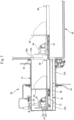
- Fig. 1 is a partially cross-sectional front view showing a schematic structure of a measurement system according to an embodiment of the present invention. First, the schematic structure of the measurement system according to the embodiment of the present invention will be described with reference to Fig. 1 .
- the measurement system is configured by the combination of a measurement apparatus 10, a glove box 20, and an airtight box 30 for measurement. Further, the combination of the glove box 20 and the airtight box 30 for measurement constitutes the airtight apparatus.
- the measurement apparatus 10 is an apparatus capable of irradiating a sample as a measurement target in the airtight box 30 for measurement with an electromagnetic wave from an energy source (a light source on an incident side) installed in the atmosphere, detecting photons emitted from the sample by a detector which is outside the airtight box 30 for measurement and installed in the atmosphere and performing analysis.
- a non-destructive inspection machine that uses X-rays , ultraviolet rays, visible rays, terahertz waves, or the like can be arbitrarily selected and applied as the measurement apparatus 10 according to the purpose of measurement.
- the airtight box 30 for measurement includes a housing 31 having a hollow therein.
- the housing 31 has a laterally elongated shape, and one side end surface 31a (right end surface in Fig. 1 ) thereof is opened.
- the opened side end surface 31a is connected to a side wall of the glove box 20 which is arranged outside side by side together with the airtight box 30 for measurement.
- the glove box 20 is provided with an opening portion 20a at a side wall portion thereof to which the housing 31 is connected, and this opening portion 20a is aligned with the opening of the side end surface 31a in the housing 31, whereby the inside of the housing 31 can be caused to communicate with the inside of the glove box 20.
- connecting means can be appropriately selected and used as a method of connecting the housing 31 to the glove box 20.
- a connecting structure by providing a flange on a side end edge of the housing 31, bringing the flange into close contact with the side wall of the glove box 20 via packing, and fixing the flange to the side wall of the glove box 20 with fasteners such as bolts and nuts or the like.
- a sample stage 34 and a transport stage 35 are provided inside the housing 31.
- the sample stage 34 is mounted on the transport stage 35.
- the transport stage 35 is transport means for transporting the sample stage 34 in an axial direction (right-and-left direction in Fig. 1 ) of the housing 31.
- the transport stage 35 can be configured by using, for example, a known slider mechanism.
- the transport stage 35 is configured to be able to transport the sample stage 34 to the inside of the glove box 20.
- the transport stage 35 is configured to be able to transport the sample stage 34 to the inside of the glove box 20.
- the sample stage 34 is provided with a sample loading portion, and the sample is loaded onto the loading portion.
- the work of loading the sample onto the sample stage 34 is performed inside the glove box 20 as described above.
- the housing 31 is provided with a measurement window 40.
- the measurement window 40 is a component for measuring the sample loaded on the sample stage 34 from the outside of the housing 31 by the measurement apparatus 10. The position at which the measurement window 40 is formed adjusted so that the sample placed inside the housing 31 can be measured by the measurement apparatus 10 to be used in combination.
- the measurement window 40 is closed by a window member to keep the inside of the housing 31 in an airtight state.
- a material to be applied to the window member is selected according to the measurement apparatus 10 to be used in combination. It is possible to perform analysis with the measurement apparatus 10 using X-rays, ultraviolet rays, visible rays, or terahertz waves by using, for example, a material such as beryllium, silicon nitride, glassy carbon, Ge (germanium), Si (silicon), diamond, sapphire, CaF2 (calcium fluoride), ZnSe (zinc selenide), ZnS (zinc sulfide), chalcogenide glass or quartz as the material for the window member.
- the airtight box 30 for measurement with which measurements can be performed by the plurality of measurement apparatuses 10.
- a measurement position A is preset inside the housing 31.
- the measurement position A preset inside the housing 31 is positionally adjusted so as to coincide with a measurement position (not shown) set in the measurement apparatus 10 when the measurement system is constructed by combining the airtight box 30 for measurement with the measurement apparatus 10.
- the airtight box 30 for measurement is provided with a sample position adjustment mechanism 41.
- Various moving mechanisms capable of moving and adjusting the sample so that the measurement position coincides with the measurement position A can be applied to the sample position adjustment mechanism 41.
- the positioning in the axial direction of the housing 31 can be realized by a configuration in which the transport stage 35 is provided with a stopper 42, and the movement of the transport stage 35 is stopped by the stopper 42 when the sample loaded on the sample stage 34 has reached the measurement position A.
- the positioning in the height direction can be realized by incorporating an elevating mechanism 43 into the sample stage 34 and adjusting the height position of the sample by driving the elevating mechanism 43.
- the front-and-rear positions of the sample stage 34 and the transport stage 35 may be adjusted in advance according to the measurement position A. Further, if necessary, a front-and-rear drive mechanism may be incorporated in the sample stage 34.
- the elevating mechanism 43 incorporated in the sample stage 34 is controlled to be driven based on a control signal from a controller 50 installed in the measurement apparatus 10, and positions the sample loaded on the sample stage 34 at the measurement position A.
- the measurement window 40 described above is formed at a place corresponding to the measurement position A set inside the housing 31.
- the measurement window 40 is formed in the housing 31 while positionally adjusted so that the measurement apparatus 10 can measure the sample placed at the measurement position A set inside the housing 31 through the measurement window 40.
- a pipe 60 is connected to each of the glove box 20 and the housing 31 of the airtight box 30 for measurement.
- the pipe 60 is configured to be connectable to any one of a vacuum suction pump 62 and an inert gas supply source 63 by switching a valve 61.
- the measurement system (and the airtight apparatus) of the present embodiment connects the pipe 60 to not only the glove box 20, but also the housing 31 of the airtight box 30 for measurement, whereby the inside of the housing 31 can be directly evacuated and an inert gas can be directly supplied into the housing 31. Therefore, the inside of the housing 31 can be quickly set to the same atmospheric state as the inside of the glove box 20.
- the glove box 20 is provided with a blocking member 22 for blocking the opening portion 20a.
- the blocking member 22 is configured so as to be manually operated from the inside of the glove box 20 to be moved to and fixed at a position where the opening portion 20a is blocked.
- the inside of the glove box 20 is partitioned off from the inside of the housing 31 by the blocking member 22, whereby it is possible to prepare a work environment to be independently performed in each of the boxes 20 and 30 when maintenance of the glove box 20 and the airtight box 30 for measurement is performed or the like.
- a maintenance work in the glove box 20 can be performed while maintaining the atmosphere inside the glove box 20.
- the maintenance of the airtight box 30 for measurement can be performed independently while maintaining the atmosphere inside the glove box 20.
- Fig. 2 is a perspective view showing the appearance of the measurement system according to the present embodiment in which the measurement apparatus is an X-ray diffraction apparatus
- Fig. 3A is a plan view showing the appearance of the measurement system according to the present embodiment
- Fig. 3B is a front view showing the appearance of the measurement system according to the present embodiment.
- the measurement system is configured by the combination of the X-ray diffraction apparatus 10 as the measurement apparatus, the glove box 20, and the airtight box 30 for measurement.
- the X-ray diffraction apparatus 10 is an apparatus often used in material study because it can provide information on the crystallinity, crystal structure, and crystal orientation of a material in a non-destructive and non-contact manner and can identify unknown substances.
- the X-ray diffraction apparatus 10 includes an X-ray source for generating X-rays, a goniometer for accurately measuring an angle, and an X-ray detector for measuring X-ray intensity, and data processing system for controlling these components and calculates count values.
- examples of the goniometer include a ⁇ -2 ⁇ type goniometer in which the position of the X-ray source is fixed and the sample is rotated by an angle of ⁇ at the same time when the X-ray detector is rotated by an angle of 2 ⁇ , and a ⁇ - ⁇ type goniometer in which the X-ray source and the X-ray detector operate while keeping the same angle with respect to a horizontally arranged sample.
- X-ray diffraction apparatus 10 These components constituting the X-ray diffraction apparatus 10 are accommodated and arranged inside an X-ray shielding cover 11, and a safety measure is taken to prevent X-rays from leaking to the outside during measurement.
- the X-ray shielding cover 11 shown in the figure is provided with opening/closing doors 12 on the front surface thereof.
- a part of the housing 31 of the airtight box 30 for measurement is inserted into the X-ray shielding cover 11 so that the part of the housing 31 penetrates through the opening/closing doors 12.
- Fig. 4 is a perspective view showing the appearance of the airtight box for measurement connected to the side wall of the glove box.
- the airtight apparatus of the present embodiment is constructed by the combination of the glove box 20 and the airtight box 30 for measurement as shown in figures.
- the airtight box 30 for measurement includes a housing 31, a transport stage 35, and a sample stage 34.
- the housing 31 is connected to the side wall of the glove box 20, and the inside of the housing 31 communicates with the inside of the glove box 20.
- the housing 31 is made of a material that shields X-rays, and X-rays do not intrude into the housing 31 from portions other than the measurement window 40.
- the transport stage 35 transports the sample stage 34 in the axial direction of the housing 31, and further extends the transport path thereof to the inside of the glove box 20.
- Fig. 5A is a perspective view showing the appearance of the housing constituting the airtight box for measurement
- Fig. 5B is a perspective view showing the two-divided structure of the housing.
- the housing 31 is hollow therein and has a laterally elongated shape, and one side end surface 31a thereof is opened.
- a flange (side end flange 32) is formed on the side end edge of the housing 31 which is a peripheral edge of the opening.
- a connection structure is constructed in the housing 31 by bringing the side end flange 32 into contact with the side wall of the glove box 20 via a packing (not shown) and fixing the side end flange 32 to the side wall of the glove box 20 with fasteners such as bolts and nuts or the like (see Fig. 4 ).
- the housing 31 is divided into two parts at a middle portion in the axial direction, and a housing element (a housing base end portion 31A) on a base end portion side with respect to the middle portion is kept to be connected to the side wall of the glove box 20 whereas a housing element (a housing tip portion 31B) on a tip portion side with respect to the middle portion is freely detachable.
- flanges are formed at joint portions of the housing base end portion 31A and the housing tip end portion 31B, and the middle flanges 33 are brought into contact with each other via a packing (not shown) and fastened to each other by using fasters such as bolts and nuts or the like, thereby constructing an integrated housing 31.
- housing tip portion 31B can be easily separated from the housing base end portion 31A by merely removing the fasteners. By removing the housing tip portion 31B in this way, operations such as maintenance and adjustment of the sample stage 34 and the transport stage 35 provided inside the housing 31 or change of the configuration of the sample stage 34 can be easily and quickly performed.
- the measurement position A is set inside the housing 31.
- the housing 31 is arranged relatively to the X-ray diffraction apparatus 10 in a state where the measurement position A is positioned at a measurement position set in the X-ray diffraction apparatus 10 (hereinafter may be referred to as an X-ray irradiation position).
- the sample is loaded on the sample stage 34 and is arranged at the measurement position A through the transport operation by the transport stage 35 and the elevating operation by the sample stage 34.
- the X-ray diffraction apparatus 10 irradiates the sample placed at the measurement position A inside the housing 31 with X-rays, and detects diffracted X-rays reflected from the sample by the X-ray detector.
- Fig. 6 is a side cross-sectional view showing the measurement window provided in the housing.
- the measurement window 40 includes an incidence-side measurement window 40a and an emission-side measurement window 40b.
- the incidence-side measurement window 40a is provided at a place where X-rays from the X-ray source 13 can be incident therethrough and the surface of the sample placed at the measurement position A can be irradiated with the X-rays.
- the emission-side measurement window 40b is provided at a place where diffracted X-rays reflected from the surface of the sample placed at the measurement position A can be emitted to the X-ray detector 14 provided outside.
- the measurement window 40 is blocked by a window member made of a material (for example, beryllium) having a characteristic of blocking the atmosphere, but transmitting X-rays therethrough.
- a window member made of a material (for example, beryllium) having a characteristic of blocking the atmosphere, but transmitting X-rays therethrough.
- the measurement window 40 can be formed in a continuous linear shape extending from an upper portion of the front surface to an upper portion of the back surface through the upper surface, for example.
- Fig. 7 is a front view showing the appearance of the transport stage.
- the transport stage 35 is configured so that a slider 37 slides along a guide rail 36 fixed to the floor surface of the housing 31 to enable the sample stage 34 to be transported to the inside of the glove box 20.
- the sample stage 34 is mounted on the upper surface of the slider 37.
- the slider 37 is provided with an operating handle 38 at an end portion thereof on the glove box 20 side.
- the operator can grasp the operating handle 38 from the inside of the glove box 20 and easily move the slider 37.
- the slider 37 includes an intermediate slider and an upper slider, and the intermediate slider engages with the upper slider and moves integrally with the upper slider in a process of moving the upper slider to the tip portion of the housing 31.
- the sample stage 34 can be pulled out from the housing 31 and moved to the inside of the glove box 20.
- the slider 37 of the transport stage 35 is provided with an X-ray shielding member 44 at a position where the X-ray shielding member 44 is closer to the glove box 20 than the sample stage 34.
- the X-ray shielding member 44 is formed in a plate-like shape with a material capable of shielding X-rays, and arranged along the cross-section of the housing 31.
- the internal space of the housing 31 is partitioned off by the X-shielding member 44. Therefore, scattered X-rays generated around the sample stage 34 during the X-ray diffraction measurement are shielded by the housing 31 and the X-ray shielding member 44, so that leakage of the X-rays to the glove box 20 side can be prevented.
- Figs. 8A and 8B are front views showing the sample position adjustment mechanism to the measurement position.
- the measurement position A is preset inside the housing 31.
- the stopper 42 is fixedly provided inside the housing 31 and on the floor surface near the tip of the housing 31.
- the stopper 42 abuts against the sample stage 34 that has been moved to the tip of the housing 31 by the transport stage 35, thereby restricting the movement of the sample stage 34.
- the setup position of the stopper 42 is adjusted so that when the sample stage 34 abuts against the stopper 42, the sample loaded on the sample stage 34 is positioned at the same position in the axial position as the measurement position A set in the housing 31.
- the sample stage 34 is incorporated with the elevating mechanism 43 for adjusting the height position of the sample.
- the position adjustment in the height direction with respect to the measurement position A set in the housing 31 is performed by the elevating mechanism 43.
- the stopper 42 and the elevating mechanism 43 constitute the sample position adjustment mechanism 41 for positioning the sample loaded on the sample stage 34 at the measurement position A.
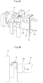
- Fig. 9A is a perspective view showing a structure in which the tip portion of the housing is fixed to the goniometer of the X-ray diffraction apparatus
- Fig. 9B is an enlarged front view showing a fixed structure of the tip portion.
- the tip portion of the housing 31 is fixed to the goniometer 15 by using the positioning member 16 with the transport stage 35 abutting against the stopper 42 so as to cause the measurement position A set inside the housing 31 to coincide with the X-ray irradiation position set in the X-ray diffraction apparatus 10.
- the tip portion of the housing 31 is prevented from sagging, and the measurement position A can be stably positioned at the X-ray irradiation position.
- the X-ray diffraction apparatus (measurement apparatus) 10 and the airtight apparatus can be easily separated from each other, so that each of the X-ray diffraction apparatus 10 and the airtight apparatus can be used as a single apparatus.
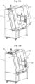
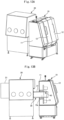
- Figs. 10A, 10B , 11A, and 11B are diagrams showing an X-ray shielding structure provided between the opening/closing door of the X-ray diffraction apparatus and an intermediate flange of the housing.
- Figs. 10A and 10B are perspective views that give a bird's-eye view of the appearance of the X-ray diffraction apparatus and the airtight box for measurement.
- Fig. 11A is a perspective view of cutouts formed in the opening/closing door as viewed from the back surface side.
- Fig. 11B is a perspective view of the X-ray shielding structure as viewed from the back surface side of the opening/closing door (that is, the inside of an X-ray shielding cover).
- cutouts 17 and 17 are formed in the opening/closing doors 12 provided on the front surface of the X-ray shielding cover 11. These cutouts 17 and 17 form an opening for inserting a part of the housing 31 into the X-ray shielding cover 11. These cutouts 17 and 17 mate with each other while the opening/closing doors 12 are closed, thereby forming one opening (see Fig. 10B ).
- the housing tip end portion 31B shown in Fig. 5A is inserted from the cutouts 17 into the X-ray shielding cover 11 and arranged there.
- the intermediate flange 33 of the housing 31 is arranged so as to cover the peripheral edge portions of the cutouts 17 from the back surface side of the opening/closing doors 12.
- the intermediate flange 33 of the housing 31 constitutes the X-ray shielding structure for the cutouts 17.
- a closing check sensor 18 is installed on the opening/closing doors 12, and the closing check sensor 18 detects a closed state of the opening/closing doors 12.
- an X-ray shielding check sensor 19 is installed to be shared to the opening/closing door and the intermediate flange 33, and the X-ray shielding check sensor 19 detects that the peripheral edge portions of the cutouts 17 are covered by the intermediate flange 33 of the housing 31 from the back surface side.
- the foregoing configuration may be modified so that the closed state of the opening/closing doors 12 can be also detected by the sensor (X-ray shielding check sensor 19) provided to be shared to the opening/closing door 12 and the intermediate flange 33.
- the sensor (closing check sensor 18) provided to be shared to the opening/closing doors 12 may be omitted.
- Fig. 12 is a perspective view showing the pipes connected to the glove box and the housing of the airtight box for measurement, and the blocking member for blocking the opening portion of the glove box.
- the pipe 60 is connected to each of the glove box 20 and the housing 31 of the airtight box 30 for measurement.
- these pipes 60 are configured to be connectable to any one of the vacuum suction pump 62 and the inert gas supply source 63 by switching the valve 61.
- the blocking member 22 is freely attachable to and detachable from the opening portion 20a of the glove box 20.
- connection of the pipes 60 to the glove box 20 and the housing 31 as described above makes it possible to set the inside of the airtight box 30 for measurement to the same atmospheric state as the inside of the glove box 20 even when the opening portion 20a of the glove box 20 is blocked by the blocking member 22 during maintenance of the airtight box 30 for measurement.
- connection of the pipe 60 to the airtight box 30 for measurement makes it possible to uniformly and quickly set the inside of the airtight box 30 for measurement to the same atmospheric state as the inside of the glove box 20.
- the measurement system having the specific configuration described above can measure an anaerobic sample under an environment where the atmosphere is blocked.
- a required atmosphere such as a vacuum atmosphere or an inert gas atmosphere is formed inside the glove box 20 and the housing 31.
- the inside of the housing 31 connected to the glove box 20 can be forcibly exhausted in a short time by a vacuum suction pump. Further, after the forced exhaust by the vacuum suction pump, inert gas can be purged and enclosed to form a required atmosphere.
- the X-ray diffraction apparatus 10 is operated while the sample stage 34 in the housing 31 is caused to abut against the stopper 42 (see Fig. 7 ), thereby performing a height adjustment operation for the sample loading portion called half-split. Through this operation, the height of the sample loading portion is adjusted to the measurement position A in the housing 31.
- a measurement target sample and necessary tools and the like are inserted into the glove box 20 via the antechamber 21 which is arranged side by side together with the glove box 20.
- the operator puts on the rubber gloves provided in the glove box 20 and operates the sample in the glove box 20 from the outside to execute a pretreatment for X-ray diffraction measurement.
- the sample stage 34 installed inside the housing 31 is moved to the inside of the glove box 20, and the sample is loaded onto the sample stage 34.
- the sample stage 34 is moved into the housing 31, and stopped when it abuts against the stopper 42 (see Fig. 7 ).
- the sample is placed at the measurement position A by stopping the sample stage 34 at a position where the sample stage 34 abuts against the stopper 42.
- the X-ray diffraction apparatus 10 is operated to perform X-ray diffraction measurement on the sample in the housing 31.
- the sample stage 34 in the housing 31 is moved to the inside of the glove box 20 again (see Fig. 4 ), and the measured sample is removed from the sample stage 34.
- the sample is taken out to the outside via the antechamber 21.
- the airtight box for measurement according to the present invention can be configured by using a well-known glove box.
- an existing glove box may be provided with a connecting unit to be connected to a connecting unit of the housing 31.
- a sample stage (a component for placing the sample at the measurement position) which has been provided in the existing measurement apparatus is removed in advance, and the sample stage which has been provided inside the airtight box for measurement is used.
- a cutout corresponding to the cutout 17 described above is formed in the opening/closing door, and a part of the housing of the airtight box for measurement is inserted into the inside of the opening/closing door through the cutout.
- the sample position adjustment mechanism for positioning the sample loaded on the sample stage to the measurement position may be configured by incorporating the sample stage with an XYZ table capable of performing not only position adjustment in an up-and-down direction (Z direction), but also position adjustment in an axial direction (Y direction) and a front-and-rear or lateral direction (X direction) of the housing.
- Figs.1 and 12 show the configuration in which the branched pipes 60 are connected to the glove box 20 and the housing 31 of the airtight box 30 for measurement so that the glove box 20 and the housing 31 of the airtight box 30 for measurement communicate with the vacuum suction device and the inert gas supply source.
- the present invention is not limited to the above configuration, and the pipes may be configured as follows.
- pipes may be independently connected to the glove box 20 and the housing 31 of the airtight box 30 for measurement respectively so that each of the glove box 20 and the housing 31 of the airtight box 30 for measurement individually communicates with the vacuum suction device and the inert gas supply source.
- the pipes to communicate with the vacuum suction device and the inert gas supply source may be connected to a plurality of places in the glove box 20 and the housing 31 of the airtight box 30 for measurement, if necessary.
- the pipes communicating with the vacuum suction device and the inert gas supply source may be connected to not only the glove box 20 and the housing 31 of the airtight box 30 for measurement, but also, for example, the antechamber 21 (pass box) attached to the glove box 20.
- the present invention may be configured so that the shaft portion of the goniometer 15 is provided with an insertion hole 15a which is sized to enable the housing 31 of the airtight box 30 for measurement to pass therethrough, the housing 31 of the airtight box 30 for measurement is inserted from the back side of the goniometer 15 through the insertion hole 15a, and a part of the housing 31 is arranged in the internal space of the X-ray shielding cover 11.
- this configuration it is not necessary to provide the cutout in the opening/closing door 12. Therefore, there is no need for an X-ray shielding structure for the cutout, and further there is an advantage that the work from the front side of the X-ray diffraction apparatus 10 can be easily performed.
Landscapes
- Physics & Mathematics (AREA)
- Chemical & Material Sciences (AREA)
- Engineering & Computer Science (AREA)
- General Engineering & Computer Science (AREA)
- High Energy & Nuclear Physics (AREA)
- Health & Medical Sciences (AREA)
- Crystallography & Structural Chemistry (AREA)
- Life Sciences & Earth Sciences (AREA)
- Analytical Chemistry (AREA)
- Biochemistry (AREA)
- General Health & Medical Sciences (AREA)
- General Physics & Mathematics (AREA)
- Immunology (AREA)
- Pathology (AREA)
- Analysing Materials By The Use Of Radiation (AREA)
Claims (13)
- Luftdichte Vorrichtung umfassend:eine luftdichte Box (30) zur Messung, um darin eine Probe zu platzieren, die durch eine außerhalb installierte Röntgenanalysevorrichtung (10) zu messen ist; undeine Glove-Box (20), die mit der luftdichten Box (30) zur Messung verbunden ist,wobei die luftdichte Box (30) zur Messung umfasst:ein Gehäuse (31), das darin hohl ist und eine Verbindungseinheit zum Verbinden des Gehäuses (31) mit der Glove-Box (20) aufweist;einen Probentisch (34), der einen Probenladeabschnitt umfasst;ein Messfenster (40), das in dem Gehäuse (31) vorgesehen ist, um eine auf den Probentisch (34) geladene Probe von der Außenseite durch die Röntgenanalysevorrichtung (10) zu messen, wobei die Verbindungseinheit des Gehäuses (31) zur Verbindung mit der Glove-Box (20), die außerhalb angeordnet ist, Seite an Seite zusammen mit der luftdichten Box (30) zur Messung ausgelegt ist, derart, dass die Innenseite des Gehäuses (31) mit der Innenseite der Glove-Box (20) in Verbindung steht, und die Innenseite von jedem des Gehäuses (31) und der Glove-Box (20) in einen luftdichten Zustand versetzt wird;gekennzeichnet durchein Röntgenabschirmelement (44), das zum Abschirmen des Eindringens von Röntgenstrahlen von der Innenseite des Gehäuses (31) in die Glove-Box (20) angeordnet ist.
- Luftdichte Vorrichtung nach Anspruch 1, wobei die luftdichte Box (30) ferner einen Transporttisch (35) umfasst, der in dem Gehäuse (31) installiert und dazu konfiguriert ist, den Probentisch (34) zu transportieren, wobei der Transporttisch (35) dazu konfiguriert ist, einen Transportweg des Probentisches (34) bis zu der Innenseite der mit dem Gehäuse (31) verbundenen Glove-Box (20) zu erstrecken.
- Luftdichte Vorrichtung nach Anspruch 1 oder 2, wobei eine Messposition (A) innerhalb des Gehäuses (31) eingestellt ist, und die luftdichte Box (30) zur Messung ferner einen Probenpositionsanpassungsmechanismus (41) zum Positionieren der auf den Probentisch (34) geladenen Probe an der Messposition (A) umfasst.
- Luftdichte Vorrichtung nach einem der Ansprüche 1 bis 3, ferner umfassend ein Rohr (60), das mit der Innenseite des Gehäuses (31) in Verbindung steht, wobei das Rohr (60) dazu konfiguriert ist, mit einem Vakuumsaugrohr (62) und/oder einer Inertgaszufuhrquelle (63) verbunden zu sein.
- Luftdichte Vorrichtung nach einem der Ansprüche 1 bis 4, wobei in der luftdichten Box (30) zur Messung, die so konfiguriert ist, dass Röntgenstrahlen durch das Messfenster (40) einfallen und ausgestrahlt werden, das Gehäuse (31) aus einem Material gebildet ist, das Röntgenstrahlen abschirmt, und das Messfenster (40) aus einem Material gebildet ist, das Röntgenstrahlen durchlässt.
- Luftdichte Vorrichtung nach Anspruch 2, wobei der Transporttisch (35) eine Führungsschiene (36), die an einer Bodenoberfläche des Gehäuses (31) fixiert ist, und eine Gleiteinrichtung (37) umfasst, die entlang der Führungsschiene (36) gleitet, der Probentisch (34) an einer oberen Oberfläche der Gleiteinrichtung (37) montiert ist, und das Röntgenabschirmelement (44) an einer Position näher bei der Glove-Box (20) als dem Probentisch (34) in der Gleiteinrichtung (37) vorgesehen ist.
- Luftdichte Vorrichtung nach Anspruch 1 bis 6, wobei die Glove-Box (20) ein Blockierelement (22) umfasst, das dazu konfiguriert ist, einen Öffnungsabschnitt zu blockieren, der mit der Innenseite des Gehäuses (31) in Verbindung steht, um die Innenseite der Glove-Box (20) von der Innenseite des Gehäuses (31) abzutrennen, wodurch die Innenseite der Glove-Box (20) in einen luftdichten Zustand versetzt wird.
- Messsystem umfassend:die luftdichte Vorrichtung nach Anspruch 1 bis 7; undeine Röntgenanalysevorrichtung (10),wobei die Röntgenanalysevorrichtung (10) dazu konfiguriert ist, eine auf den Probentisch (34) geladene Probe durch das Messfenster (40) zu messen.
- Messsystem nach Anspruch 8, wobei das Messsystem dazu konfiguriert ist, die Innenseite von jedem des Gehäuses (31) und der Glove-Box (20) in einen luftdichten Zustand zu versetzen, und die Röntgenanalysevorrichtung (10) eine Steuereinrichtung zum Ausgeben eines Steuersignals zum Steuern eines Probenpositionsanpassungsmechanismus (41) zum Positionieren der auf den Probentisch (34) geladenen Probe an einer Messposition (A) umfasst.
- Messsystem nach Anspruch 8 oder 9, wobei die Röntgenanalysevorrichtung (10) ein Goniometer (15) umfasst, und das Messsystem ferner ein Positionierelement (16) zum Fixieren und Positionieren der luftdichten Box (30) zur Messung an dem Goniometer (15) umfasst.
- Messsystem nach einem der Ansprüche 8 bis 10, wobei die Röntgenanalysevorrichtung (10) eine Öffnungs-/Schließtür (12) umfasst, die Messposition (A) innerhalb der Öffnungs-/Schließtür (12) eingestellt ist, und die Öffnungs-/Schließtür (12) einen Ausschnitt (17) umfasst, durch den ein Teil des Gehäuses (31) eingefügt ist, um das Messfenster (40) an einer Position entsprechend der Messposition (A) anzuordnen.
- Messsystem nach Anspruch 11, wobei der in der Öffnungs-/Schließtür (12) gebildete Ausschnitt (17) erlaubt, dass ein Teil des Gehäuses (31), der einen Flansch (33) an einer Zwischenposition von diesem aufweist, durch den Ausschnitt (17) hindurchgeht, und kleiner gebildet ist als eine äußere Form des Flansches (33), und ein Montageabschnitt des Flansches (33) nahe der Innenseite der Öffnungs-/Schließtür (12) vorgesehen ist.
- Messsystem nach Anspruch 12, wobei die Röntgenanalysevorrichtung (10) ferner einen Sensor (18, 19) zum Detektieren eines Zustands umfasst, wo die Öffnungs-/Schließtür (12) geschlossen ist und der Flansch (33) an dem Montageabschnitt montiert ist.
Applications Claiming Priority (2)
| Application Number | Priority Date | Filing Date | Title |
|---|---|---|---|
| JP2019215183A JP7323892B2 (ja) | 2019-11-28 | 2019-11-28 | 測定用気密ボックス、気密装置、測定システムおよび測定装置 |
| EP20208530.4A EP3828533A3 (de) | 2019-11-28 | 2020-11-19 | Luftdichter behälter für röntgendiffraktionsmessungen |
Related Parent Applications (1)
| Application Number | Title | Priority Date | Filing Date |
|---|---|---|---|
| EP20208530.4A Division EP3828533A3 (de) | 2019-11-28 | 2020-11-19 | Luftdichter behälter für röntgendiffraktionsmessungen |
Publications (3)
| Publication Number | Publication Date |
|---|---|
| EP4134664A2 EP4134664A2 (de) | 2023-02-15 |
| EP4134664A3 EP4134664A3 (de) | 2023-02-22 |
| EP4134664B1 true EP4134664B1 (de) | 2025-04-23 |
Family
ID=73726535
Family Applications (2)
| Application Number | Title | Priority Date | Filing Date |
|---|---|---|---|
| EP22197894.3A Active EP4134664B1 (de) | 2019-11-28 | 2020-11-19 | Luftdichter behälter für röntgendiffraktionsmessungen |
| EP20208530.4A Withdrawn EP3828533A3 (de) | 2019-11-28 | 2020-11-19 | Luftdichter behälter für röntgendiffraktionsmessungen |
Family Applications After (1)
| Application Number | Title | Priority Date | Filing Date |
|---|---|---|---|
| EP20208530.4A Withdrawn EP3828533A3 (de) | 2019-11-28 | 2020-11-19 | Luftdichter behälter für röntgendiffraktionsmessungen |
Country Status (5)
| Country | Link |
|---|---|
| US (1) | US11942231B2 (de) |
| EP (2) | EP4134664B1 (de) |
| JP (1) | JP7323892B2 (de) |
| KR (1) | KR102886787B1 (de) |
| CN (1) | CN112858356B (de) |
Families Citing this family (8)
| Publication number | Priority date | Publication date | Assignee | Title |
|---|---|---|---|---|
| EP3961199A1 (de) * | 2020-08-24 | 2022-03-02 | Malvern Panalytical B.V. | Röntgenstrahldetektor für röntgenstrahldiffraktionsanalysevorrichtung |
| CN114018960B (zh) * | 2022-01-05 | 2022-10-25 | 山东胜宁电器有限公司 | 一种基于x射线探伤图像的缺陷分析装置 |
| US12548731B2 (en) * | 2022-09-30 | 2026-02-10 | Fei Company | Systems and methods for transferring a sample |
| CN116818198A (zh) * | 2023-06-25 | 2023-09-29 | 湖北米开罗那机电技术有限公司 | 一种手套箱手套检测装置 |
| WO2025043189A2 (en) * | 2023-08-23 | 2025-02-27 | University Of Oregon | Sample transfer apparatus for use with vacuum instruments |
| WO2025187919A1 (ko) * | 2024-03-05 | 2025-09-12 | (주)엠크래프츠 | 진공형 실험장치 |
| CN119101792A (zh) * | 2024-09-18 | 2024-12-10 | 宇寿影像科技(无锡)有限公司 | 一种用于液态金属轴承热处理及装配的设备 |
| FR3167754A1 (fr) * | 2024-10-18 | 2026-04-24 | Lemer Pax | Enceinte manuelle radio-protectrice pour la préparation de produits radiopharmaceutiques |
Family Cites Families (13)
| Publication number | Priority date | Publication date | Assignee | Title |
|---|---|---|---|---|
| JP2001153760A (ja) | 1999-11-30 | 2001-06-08 | Shimadzu Corp | 搬送用試料容器 |
| JP2007333682A (ja) * | 2006-06-19 | 2007-12-27 | Jeol Ltd | イオンビームを用いた断面試料作製装置 |
| US7644637B2 (en) | 2006-09-25 | 2010-01-12 | Omniprobe, Inc. | Method and apparatus for transfer of samples in a controlled environment |
| JP5422416B2 (ja) * | 2010-01-28 | 2014-02-19 | 株式会社日立製作所 | 試料搬送装置 |
| US8716683B2 (en) * | 2011-11-28 | 2014-05-06 | Jeol Ltd. | Ion beam processing system and sample processing method |
| JP2014086250A (ja) | 2012-10-23 | 2014-05-12 | Sumitomo Electric Ind Ltd | 分析試料搬送装置及び分析試料搬送方法 |
| JP6114938B2 (ja) | 2013-07-08 | 2017-04-19 | 国立大学法人京都大学 | X線回折装置一体型雰囲気制御グローブボックス装置、およびその製造方法 |
| JP6326352B2 (ja) * | 2014-11-19 | 2018-05-16 | 日本電子株式会社 | 試料ホルダー、試料作製装置、および位置合わせ方法 |
| JP6516569B2 (ja) | 2015-06-02 | 2019-05-22 | 株式会社日立ハイテクサイエンス | 走査プローブ顕微鏡 |
| JP6606658B2 (ja) * | 2016-08-18 | 2019-11-20 | 株式会社リガク | X線回折装置 |
| WO2019161497A1 (en) | 2018-02-22 | 2019-08-29 | Proto Patents Ltd. | Carbon fiber window for x-ray diffractometer |
| JP6843790B2 (ja) | 2018-03-13 | 2021-03-17 | 日本電子株式会社 | イオンミリング装置及び試料ホルダー |
| JP7181603B2 (ja) * | 2019-08-16 | 2022-12-01 | 株式会社リガク | X線分析用試料保持装置 |
-
2019
- 2019-11-28 JP JP2019215183A patent/JP7323892B2/ja active Active
-
2020
- 2020-11-16 KR KR1020200152723A patent/KR102886787B1/ko active Active
- 2020-11-17 US US16/950,081 patent/US11942231B2/en active Active
- 2020-11-19 EP EP22197894.3A patent/EP4134664B1/de active Active
- 2020-11-19 EP EP20208530.4A patent/EP3828533A3/de not_active Withdrawn
- 2020-11-27 CN CN202011352668.4A patent/CN112858356B/zh active Active
Also Published As
| Publication number | Publication date |
|---|---|
| CN112858356A (zh) | 2021-05-28 |
| US11942231B2 (en) | 2024-03-26 |
| US20210166829A1 (en) | 2021-06-03 |
| EP4134664A2 (de) | 2023-02-15 |
| JP7323892B2 (ja) | 2023-08-09 |
| CN112858356B (zh) | 2024-11-05 |
| EP3828533A2 (de) | 2021-06-02 |
| KR102886787B1 (ko) | 2025-11-18 |
| KR20210066718A (ko) | 2021-06-07 |
| EP4134664A3 (de) | 2023-02-22 |
| EP3828533A3 (de) | 2021-09-22 |
| JP2021085773A (ja) | 2021-06-03 |
Similar Documents
| Publication | Publication Date | Title |
|---|---|---|
| EP4134664B1 (de) | Luftdichter behälter für röntgendiffraktionsmessungen | |
| CN105675640B (zh) | 荧光x射线分析装置 | |
| CN105628724A (zh) | 荧光x射线分析装置和荧光x射线分析方法 | |
| CN117831808B (zh) | 分析检测装置及乏燃料后处理系统 | |
| WO2016088926A1 (ko) | 엑스선 차폐장치 및 차폐방법 | |
| JPH08178872A (ja) | X線非破壊検査装置 | |
| KR20220014323A (ko) | 산업 생산 라인에서 품질 관리를 수행하는 장치, 해당 방법 및 컴퓨터 프로그램 제품 | |
| CN112601952A (zh) | X射线分析装置 | |
| US7755044B2 (en) | Apparatus for working and observing samples and method of working and observing cross sections | |
| JP7392252B2 (ja) | X線蛍光分光法により製品を当該製品の組成に基づいて選択する装置、および対応する選択方法 | |
| JP7779659B2 (ja) | 放射線検査装置 | |
| KR101962710B1 (ko) | 튜브 구조 부품의 검사를 위한 엑스레이 검사 장치 및 그에 의한 검사 방법 | |
| JP3521425B2 (ja) | X線分析装置 | |
| KR20190089137A (ko) | 차폐 기능이 향상된 엑스레이 튜브 모듈 및 그에 의한 엑스레이 검사 방법 | |
| JP2003107017A (ja) | X線検査装置 | |
| JP2000171419A (ja) | X線分析装置 | |
| JP6133317B2 (ja) | マイクロプローブ補助式放射性物質分析装置 | |
| KR20160051710A (ko) | 차폐 기능이 향상된 엑스레이 튜브 모듈 및 그에 의한 엑스레이 검사 방법 | |
| JP2001021510A (ja) | X線分析装置 | |
| US12385860B1 (en) | X-ray fluorescence spectrometer | |
| CN111323394B (zh) | 一种用于放射性物质的测量系统 | |
| CA1076715A (en) | Test assembly for x-ray fluorescence analysis | |
| JPH06331574A (ja) | 分析装置 | |
| JP2000162161A (ja) | 蛍光x線分析装置 | |
| JP2003215066A (ja) | X線検査装置 |
Legal Events
| Date | Code | Title | Description |
|---|---|---|---|
| PUAI | Public reference made under article 153(3) epc to a published international application that has entered the european phase |
Free format text: ORIGINAL CODE: 0009012 |
|
| STAA | Information on the status of an ep patent application or granted ep patent |
Free format text: STATUS: THE APPLICATION HAS BEEN PUBLISHED |
|
| PUAL | Search report despatched |
Free format text: ORIGINAL CODE: 0009013 |
|
| AC | Divisional application: reference to earlier application |
Ref document number: 3828533 Country of ref document: EP Kind code of ref document: P |
|
| AK | Designated contracting states |
Kind code of ref document: A2 Designated state(s): AL AT BE BG CH CY CZ DE DK EE ES FI FR GB GR HR HU IE IS IT LI LT LU LV MC MK MT NL NO PL PT RO RS SE SI SK SM TR |
|
| AK | Designated contracting states |
Kind code of ref document: A3 Designated state(s): AL AT BE BG CH CY CZ DE DK EE ES FI FR GB GR HR HU IE IS IT LI LT LU LV MC MK MT NL NO PL PT RO RS SE SI SK SM TR |
|
| RIC1 | Information provided on ipc code assigned before grant |
Ipc: B25J 21/02 20060101ALI20230118BHEP Ipc: G01N 23/20025 20180101AFI20230118BHEP |
|
| STAA | Information on the status of an ep patent application or granted ep patent |
Free format text: STATUS: REQUEST FOR EXAMINATION WAS MADE |
|
| STAA | Information on the status of an ep patent application or granted ep patent |
Free format text: STATUS: EXAMINATION IS IN PROGRESS |
|
| 17P | Request for examination filed |
Effective date: 20230822 |
|
| RBV | Designated contracting states (corrected) |
Designated state(s): AL AT BE BG CH CY CZ DE DK EE ES FI FR GB GR HR HU IE IS IT LI LT LU LV MC MK MT NL NO PL PT RO RS SE SI SK SM TR |
|
| 17Q | First examination report despatched |
Effective date: 20230911 |
|
| GRAP | Despatch of communication of intention to grant a patent |
Free format text: ORIGINAL CODE: EPIDOSNIGR1 |
|
| STAA | Information on the status of an ep patent application or granted ep patent |
Free format text: STATUS: GRANT OF PATENT IS INTENDED |
|
| INTG | Intention to grant announced |
Effective date: 20241223 |
|
| GRAS | Grant fee paid |
Free format text: ORIGINAL CODE: EPIDOSNIGR3 |
|
| GRAA | (expected) grant |
Free format text: ORIGINAL CODE: 0009210 |
|
| STAA | Information on the status of an ep patent application or granted ep patent |
Free format text: STATUS: THE PATENT HAS BEEN GRANTED |
|
| AC | Divisional application: reference to earlier application |
Ref document number: 3828533 Country of ref document: EP Kind code of ref document: P |
|
| AK | Designated contracting states |
Kind code of ref document: B1 Designated state(s): AL AT BE BG CH CY CZ DE DK EE ES FI FR GB GR HR HU IE IS IT LI LT LU LV MC MK MT NL NO PL PT RO RS SE SI SK SM TR |
|
| REG | Reference to a national code |
Ref country code: GB Ref legal event code: FG4D |
|
| REG | Reference to a national code |
Ref country code: CH Ref legal event code: EP |
|
| REG | Reference to a national code |
Ref country code: DE Ref legal event code: R096 Ref document number: 602020050235 Country of ref document: DE |
|
| REG | Reference to a national code |
Ref country code: IE Ref legal event code: FG4D |
|
| REG | Reference to a national code |
Ref country code: NL Ref legal event code: MP Effective date: 20250423 |
|
| PG25 | Lapsed in a contracting state [announced via postgrant information from national office to epo] |
Ref country code: NL Free format text: LAPSE BECAUSE OF FAILURE TO SUBMIT A TRANSLATION OF THE DESCRIPTION OR TO PAY THE FEE WITHIN THE PRESCRIBED TIME-LIMIT Effective date: 20250423 |
|
| REG | Reference to a national code |
Ref country code: AT Ref legal event code: MK05 Ref document number: 1788188 Country of ref document: AT Kind code of ref document: T Effective date: 20250423 |
|
| PG25 | Lapsed in a contracting state [announced via postgrant information from national office to epo] |
Ref country code: FI Free format text: LAPSE BECAUSE OF FAILURE TO SUBMIT A TRANSLATION OF THE DESCRIPTION OR TO PAY THE FEE WITHIN THE PRESCRIBED TIME-LIMIT Effective date: 20250423 Ref country code: ES Free format text: LAPSE BECAUSE OF FAILURE TO SUBMIT A TRANSLATION OF THE DESCRIPTION OR TO PAY THE FEE WITHIN THE PRESCRIBED TIME-LIMIT Effective date: 20250423 Ref country code: PT Free format text: LAPSE BECAUSE OF FAILURE TO SUBMIT A TRANSLATION OF THE DESCRIPTION OR TO PAY THE FEE WITHIN THE PRESCRIBED TIME-LIMIT Effective date: 20250825 |
|
| REG | Reference to a national code |
Ref country code: LT Ref legal event code: MG9D |
|
| PG25 | Lapsed in a contracting state [announced via postgrant information from national office to epo] |
Ref country code: NO Free format text: LAPSE BECAUSE OF FAILURE TO SUBMIT A TRANSLATION OF THE DESCRIPTION OR TO PAY THE FEE WITHIN THE PRESCRIBED TIME-LIMIT Effective date: 20250723 Ref country code: GR Free format text: LAPSE BECAUSE OF FAILURE TO SUBMIT A TRANSLATION OF THE DESCRIPTION OR TO PAY THE FEE WITHIN THE PRESCRIBED TIME-LIMIT Effective date: 20250724 |
|
| PG25 | Lapsed in a contracting state [announced via postgrant information from national office to epo] |
Ref country code: PL Free format text: LAPSE BECAUSE OF FAILURE TO SUBMIT A TRANSLATION OF THE DESCRIPTION OR TO PAY THE FEE WITHIN THE PRESCRIBED TIME-LIMIT Effective date: 20250423 |
|
| PG25 | Lapsed in a contracting state [announced via postgrant information from national office to epo] |
Ref country code: BG Free format text: LAPSE BECAUSE OF FAILURE TO SUBMIT A TRANSLATION OF THE DESCRIPTION OR TO PAY THE FEE WITHIN THE PRESCRIBED TIME-LIMIT Effective date: 20250423 |
|
| PG25 | Lapsed in a contracting state [announced via postgrant information from national office to epo] |
Ref country code: HR Free format text: LAPSE BECAUSE OF FAILURE TO SUBMIT A TRANSLATION OF THE DESCRIPTION OR TO PAY THE FEE WITHIN THE PRESCRIBED TIME-LIMIT Effective date: 20250423 |
|
| PG25 | Lapsed in a contracting state [announced via postgrant information from national office to epo] |
Ref country code: AT Free format text: LAPSE BECAUSE OF FAILURE TO SUBMIT A TRANSLATION OF THE DESCRIPTION OR TO PAY THE FEE WITHIN THE PRESCRIBED TIME-LIMIT Effective date: 20250423 |
|
| PG25 | Lapsed in a contracting state [announced via postgrant information from national office to epo] |
Ref country code: RS Free format text: LAPSE BECAUSE OF FAILURE TO SUBMIT A TRANSLATION OF THE DESCRIPTION OR TO PAY THE FEE WITHIN THE PRESCRIBED TIME-LIMIT Effective date: 20250723 |
|
| PG25 | Lapsed in a contracting state [announced via postgrant information from national office to epo] |
Ref country code: IS Free format text: LAPSE BECAUSE OF FAILURE TO SUBMIT A TRANSLATION OF THE DESCRIPTION OR TO PAY THE FEE WITHIN THE PRESCRIBED TIME-LIMIT Effective date: 20250823 |
|
| PG25 | Lapsed in a contracting state [announced via postgrant information from national office to epo] |
Ref country code: LV Free format text: LAPSE BECAUSE OF FAILURE TO SUBMIT A TRANSLATION OF THE DESCRIPTION OR TO PAY THE FEE WITHIN THE PRESCRIBED TIME-LIMIT Effective date: 20250423 |
|
| PGFP | Annual fee paid to national office [announced via postgrant information from national office to epo] |
Ref country code: DE Payment date: 20251119 Year of fee payment: 6 |
|
| PGFP | Annual fee paid to national office [announced via postgrant information from national office to epo] |
Ref country code: GB Payment date: 20251121 Year of fee payment: 6 |
|
| PG25 | Lapsed in a contracting state [announced via postgrant information from national office to epo] |
Ref country code: DK Free format text: LAPSE BECAUSE OF FAILURE TO SUBMIT A TRANSLATION OF THE DESCRIPTION OR TO PAY THE FEE WITHIN THE PRESCRIBED TIME-LIMIT Effective date: 20250423 Ref country code: SM Free format text: LAPSE BECAUSE OF FAILURE TO SUBMIT A TRANSLATION OF THE DESCRIPTION OR TO PAY THE FEE WITHIN THE PRESCRIBED TIME-LIMIT Effective date: 20250423 |
|
| PG25 | Lapsed in a contracting state [announced via postgrant information from national office to epo] |
Ref country code: CZ Free format text: LAPSE BECAUSE OF FAILURE TO SUBMIT A TRANSLATION OF THE DESCRIPTION OR TO PAY THE FEE WITHIN THE PRESCRIBED TIME-LIMIT Effective date: 20250423 |
|
| PG25 | Lapsed in a contracting state [announced via postgrant information from national office to epo] |
Ref country code: EE Free format text: LAPSE BECAUSE OF FAILURE TO SUBMIT A TRANSLATION OF THE DESCRIPTION OR TO PAY THE FEE WITHIN THE PRESCRIBED TIME-LIMIT Effective date: 20250423 |
|
| REG | Reference to a national code |
Ref country code: DE Ref legal event code: R097 Ref document number: 602020050235 Country of ref document: DE |
|
| PG25 | Lapsed in a contracting state [announced via postgrant information from national office to epo] |
Ref country code: SK Free format text: LAPSE BECAUSE OF FAILURE TO SUBMIT A TRANSLATION OF THE DESCRIPTION OR TO PAY THE FEE WITHIN THE PRESCRIBED TIME-LIMIT Effective date: 20250423 |
|
| PG25 | Lapsed in a contracting state [announced via postgrant information from national office to epo] |
Ref country code: IT Free format text: LAPSE BECAUSE OF FAILURE TO SUBMIT A TRANSLATION OF THE DESCRIPTION OR TO PAY THE FEE WITHIN THE PRESCRIBED TIME-LIMIT Effective date: 20250423 |
|
| PG25 | Lapsed in a contracting state [announced via postgrant information from national office to epo] |
Ref country code: RO Free format text: LAPSE BECAUSE OF FAILURE TO SUBMIT A TRANSLATION OF THE DESCRIPTION OR TO PAY THE FEE WITHIN THE PRESCRIBED TIME-LIMIT Effective date: 20250423 |
|
| PLBE | No opposition filed within time limit |
Free format text: ORIGINAL CODE: 0009261 |
|
| STAA | Information on the status of an ep patent application or granted ep patent |
Free format text: STATUS: NO OPPOSITION FILED WITHIN TIME LIMIT |
|
| REG | Reference to a national code |
Ref country code: CH Ref legal event code: L10 Free format text: ST27 STATUS EVENT CODE: U-0-0-L10-L00 (AS PROVIDED BY THE NATIONAL OFFICE) Effective date: 20260304 |
|
| 26N | No opposition filed |
Effective date: 20260126 |