EP4134059A1 - Kniegelenkmechanismus ohne stromquelle - Google Patents
Kniegelenkmechanismus ohne stromquelle Download PDFInfo
- Publication number
- EP4134059A1 EP4134059A1 EP21822054.9A EP21822054A EP4134059A1 EP 4134059 A1 EP4134059 A1 EP 4134059A1 EP 21822054 A EP21822054 A EP 21822054A EP 4134059 A1 EP4134059 A1 EP 4134059A1
- Authority
- EP
- European Patent Office
- Prior art keywords
- connecting base
- support assembly
- rotating shaft
- locking
- knee joint
- Prior art date
- Legal status (The legal status is an assumption and is not a legal conclusion. Google has not performed a legal analysis and makes no representation as to the accuracy of the status listed.)
- Granted
Links
Images

Classifications
-
- A—HUMAN NECESSITIES
- A61—MEDICAL OR VETERINARY SCIENCE; HYGIENE
- A61H—PHYSICAL THERAPY APPARATUS, e.g. DEVICES FOR LOCATING OR STIMULATING REFLEX POINTS IN THE BODY; ARTIFICIAL RESPIRATION; MASSAGE; BATHING DEVICES FOR SPECIAL THERAPEUTIC OR HYGIENIC PURPOSES OR SPECIFIC PARTS OF THE BODY
- A61H3/00—Appliances for aiding patients or disabled persons to walk about
- A61H3/008—Appliances for aiding patients or disabled persons to walk about using suspension devices for supporting the body in an upright walking or standing position, e.g. harnesses
-
- A—HUMAN NECESSITIES
- A61—MEDICAL OR VETERINARY SCIENCE; HYGIENE
- A61H—PHYSICAL THERAPY APPARATUS, e.g. DEVICES FOR LOCATING OR STIMULATING REFLEX POINTS IN THE BODY; ARTIFICIAL RESPIRATION; MASSAGE; BATHING DEVICES FOR SPECIAL THERAPEUTIC OR HYGIENIC PURPOSES OR SPECIFIC PARTS OF THE BODY
- A61H1/00—Apparatus for passive exercising; Vibrating apparatus; Chiropractic devices, e.g. body impacting devices, external devices for briefly extending or aligning unbroken bones
- A61H1/02—Stretching or bending or torsioning apparatus for exercising
- A61H1/0237—Stretching or bending or torsioning apparatus for exercising for the lower limbs
-
- A—HUMAN NECESSITIES
- A61—MEDICAL OR VETERINARY SCIENCE; HYGIENE
- A61H—PHYSICAL THERAPY APPARATUS, e.g. DEVICES FOR LOCATING OR STIMULATING REFLEX POINTS IN THE BODY; ARTIFICIAL RESPIRATION; MASSAGE; BATHING DEVICES FOR SPECIAL THERAPEUTIC OR HYGIENIC PURPOSES OR SPECIFIC PARTS OF THE BODY
- A61H3/00—Appliances for aiding patients or disabled persons to walk about
- A61H2003/005—Appliances for aiding patients or disabled persons to walk about with knee, leg or stump rests
-
- A—HUMAN NECESSITIES
- A61—MEDICAL OR VETERINARY SCIENCE; HYGIENE
- A61H—PHYSICAL THERAPY APPARATUS, e.g. DEVICES FOR LOCATING OR STIMULATING REFLEX POINTS IN THE BODY; ARTIFICIAL RESPIRATION; MASSAGE; BATHING DEVICES FOR SPECIAL THERAPEUTIC OR HYGIENIC PURPOSES OR SPECIFIC PARTS OF THE BODY
- A61H3/00—Appliances for aiding patients or disabled persons to walk about
- A61H2003/007—Appliances for aiding patients or disabled persons to walk about secured to the patient, e.g. with belts
-
- A—HUMAN NECESSITIES
- A61—MEDICAL OR VETERINARY SCIENCE; HYGIENE
- A61H—PHYSICAL THERAPY APPARATUS, e.g. DEVICES FOR LOCATING OR STIMULATING REFLEX POINTS IN THE BODY; ARTIFICIAL RESPIRATION; MASSAGE; BATHING DEVICES FOR SPECIAL THERAPEUTIC OR HYGIENIC PURPOSES OR SPECIFIC PARTS OF THE BODY
- A61H2201/00—Characteristics of apparatus not provided for in the preceding codes
- A61H2201/12—Driving means
- A61H2201/1207—Driving means with electric or magnetic drive
- A61H2201/1215—Rotary drive
-
- A—HUMAN NECESSITIES
- A61—MEDICAL OR VETERINARY SCIENCE; HYGIENE
- A61H—PHYSICAL THERAPY APPARATUS, e.g. DEVICES FOR LOCATING OR STIMULATING REFLEX POINTS IN THE BODY; ARTIFICIAL RESPIRATION; MASSAGE; BATHING DEVICES FOR SPECIAL THERAPEUTIC OR HYGIENIC PURPOSES OR SPECIFIC PARTS OF THE BODY
- A61H2201/00—Characteristics of apparatus not provided for in the preceding codes
- A61H2201/14—Special force transmission means, i.e. between the driving means and the interface with the user
- A61H2201/1418—Cam
-
- A—HUMAN NECESSITIES
- A61—MEDICAL OR VETERINARY SCIENCE; HYGIENE
- A61H—PHYSICAL THERAPY APPARATUS, e.g. DEVICES FOR LOCATING OR STIMULATING REFLEX POINTS IN THE BODY; ARTIFICIAL RESPIRATION; MASSAGE; BATHING DEVICES FOR SPECIAL THERAPEUTIC OR HYGIENIC PURPOSES OR SPECIFIC PARTS OF THE BODY
- A61H2201/00—Characteristics of apparatus not provided for in the preceding codes
- A61H2201/16—Physical interface with patient
- A61H2201/1602—Physical interface with patient kind of interface, e.g. head rest, knee support or lumbar support
- A61H2201/164—Feet or leg, e.g. pedal
-
- A—HUMAN NECESSITIES
- A61—MEDICAL OR VETERINARY SCIENCE; HYGIENE
- A61H—PHYSICAL THERAPY APPARATUS, e.g. DEVICES FOR LOCATING OR STIMULATING REFLEX POINTS IN THE BODY; ARTIFICIAL RESPIRATION; MASSAGE; BATHING DEVICES FOR SPECIAL THERAPEUTIC OR HYGIENIC PURPOSES OR SPECIFIC PARTS OF THE BODY
- A61H2201/00—Characteristics of apparatus not provided for in the preceding codes
- A61H2201/16—Physical interface with patient
- A61H2201/1602—Physical interface with patient kind of interface, e.g. head rest, knee support or lumbar support
- A61H2201/165—Wearable interfaces
-
- A—HUMAN NECESSITIES
- A61—MEDICAL OR VETERINARY SCIENCE; HYGIENE
- A61H—PHYSICAL THERAPY APPARATUS, e.g. DEVICES FOR LOCATING OR STIMULATING REFLEX POINTS IN THE BODY; ARTIFICIAL RESPIRATION; MASSAGE; BATHING DEVICES FOR SPECIAL THERAPEUTIC OR HYGIENIC PURPOSES OR SPECIFIC PARTS OF THE BODY
- A61H2201/00—Characteristics of apparatus not provided for in the preceding codes
- A61H2201/50—Control means thereof
- A61H2201/5058—Sensors or detectors
- A61H2201/5069—Angle sensors
Definitions
- the present invention relates to the technical field of rehabilitation walking aids, in particular to a knee joint mechanism without a power source.
- a lightweight wearable lower limb rehabilitation walking-aiding exoskeleton for hemiplegic patients is provided, wherein a knee joint driving mechanism comprises a second limiting end cap, a second flexible flange, a second coupling, a second rigid wheel flange, a second harmonic reducer, a second motor flange and a second motor; and the knee joint driving mechanism requires two knee joint driving mechanisms, one on the left and one on the right, which is costly, and the weight and size of the exoskeleton machine are increased. It requires a continuous power supply to the two knee joint driving mechanisms during use, which results in high energy consumption, and generally requires high-capacity batteries. In addition, the use of high-capacity batteries also brings about an increase in cost and weight.
- a lower limb exoskeleton robot with a four-bar-linkage knee joint is provided, wherein a keen joint comprises an upper knee joint support block and a lower knee joint support block, which are connected into a four-bar-linkage structure through a first knee joint swinging plate and a second knee joint swinging plate, and a movement of the lower knee joint support block is driven through a hydraulic cylinder, which results in a greater overall size and weight and higher cost.
- an adaptive knee joint mechanism and device for wearable exoskeleton comprises a thigh rod, a shank rod, a flexible knee joint, a knee Bowden cable, a knee Bowden cable winding cylinder and a knee joint driving motor.
- the overall structure is complex, the energy consumption generated during use is high, and the Bowden cable is at risk of fracture over time.
- a knee joint without a power source is further provided.
- a driven type lower limb motion force assisting exoskeleton device is provided, which stores and releases energy by a torsion spring to achieve an effect of buffering and saving labor.
- the device is small in size and light in weight, the weight-bearing support effect is poor during the patient's walking.
- the whole leg of the exoskeleton is stressed, its knee joint is not completely locked, and can still rotate along the axial direction. If the patient's leg is weak or inadvertent, it is easy to lose control of support and fall, resulting in secondary injury.
- the present invention provides a knee joint mechanism without a power source, wherein power is supplied by a hip of an exoskeleton robot, a first angle sensor or a second angle sensor controls a drive assembly to drive an unlocking member to make a locking member unlocked or locked, and a shank drives the locking member to rotate or form support through a shank support assembly under the action of gravity, thus avoiding setting a power source at the knee joint.
- the overall structure is light, the size is small, and the battery life is long, which can effectively improve the practicability of the exoskeleton rehabilitation robot.
- the present invention provides a knee joint mechanism without a power source, which comprises:
- the locking block is provided with an arc-shaped surface or an inclined surface at a side that is close to the unlocking member, which makes the structure between the locking block and the unlocking member more compact to achieve a space-saving effect while the unlocking member effectively controls the locking member.
- a lower end of the locking cam is provided with a U-shaped groove in which the shank support assembly is positioned and is fixedly mounted on the first rotating shaft, to lock and fix the shank support assembly on the first rotating shaft, and then the U-shaped groove ensures that the shank support assembly does not rotate relatively on the locking cam, so that the connection between the shank support assembly and the connecting base is more stable, the structure is more compact and space-saving.
- the unlocking member comprises an unlocking block attached to the rear side of the connecting base and a second rotating shaft rotationally disposed in the connecting base and fixedly connected to the unlocking block; and the unlocking block is fitted with the locking member, the connecting base is provided with a second bearing sleeved on the second rotating shaft, the second rotating shaft is connected to the drive assembly after passing through the connecting base, and the drive assembly drives the second rotating shaft to rotate in the second bearing, so that the rotation of the second rotating shaft is more flexible.
- the drive assembly comprises a worm gear, a third rotating shaft and a motor, wherein the worm gear comprises a worm wheel and a worm gear which are fitted with each other;
- the rear side of the connecting base is also fixedly provided with a second limiting member for limiting a rotation range of the unlocking member, the second limiting member is located at one side of the unlocking member that is away from a rotation direction of the locking member, so as to prevent a failure in a process of the motor driving the second rotating shaft and the unlocking member to rotate through the worm gear, resulting in the locking member rotating too far to go beyond a control range of the unlocking member.
- the rear side of the connecting base is provided with a profiling groove for mounting the thigh support assembly, which ensures that the thigh support assembly is firmly connected to the connecting base and avoids a relative rotation of the thigh support assembly on the connecting base.
- the rear side of the connecting base is mounted with a back cover, which is close to an upper end of the connecting base and fitted with the locking member to form a seal for protecting various parts mounted on the rear side of the connecting base while improving the aesthetic value.
- the front side of the connecting base is mounted with a front cover
- the second angle sensor is mounted on the inner side of the front cover, which is used for protecting various parts mounted on the front side of the connecting base while improving the aesthetic value.
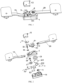
- the knee joint mechanism without a power source provided by the present invention comprises a thigh support assembly, a connecting base, a shank support assembly and a locking mechanism;
- the thigh support assembly is fixed at a thigh of an exoskeleton robot, and a first angle sensor is disposed on a hip
- the connecting base is mounted with a second angle sensor
- the locking mechanism includes a motor, a worm gear, a locking member fixedly connected to the shank support assembly, an unlocking member and a first limiting member for limiting a rotation range of the locking member; when the mechanism supports the human body to bear weight, the unlocking member and the first limiting member firmly fix the locking member, so that the thigh support assembly, the connecting base and the shank support assembly are maintained at an ergonomic angle to support the weight of human body; through a worm gear and a motor self-locking unlocking member, a good weight-bearing support effect is achieved; when the exoskeleton robot drives
- the present invention provides a knee joint mechanism without a power source, which comprises:
- the connecting base and the shank support assembly will reach the predetermined ergonomic angle, i.e., 180°, so as to realize the locking of the locking member and achieve a supporting effect.
- the locking member 2 comprises a locking cam 21 and a first rotating shaft 22, wherein the locking cam 21 is attached to the rear side of the connecting base 1, and the first rotating shaft 22 is rotationally disposed in the connecting base 1 and fixedly connected to the locking cam 21; and the locking cam 21 is provided with a locking block 211 movably inserted between the unlocking member 3 and the first limiting member 201, and the connecting base 1 is provided with a first bearing 23 sleeved on the first rotating shaft 22.
- the first bearing 23 is pressed into a shaft hole of the connecting base 1, and pressed in a constant section ring 231 for preventing disengagement; then the first rotating shaft 22 is pressed in an inner ring of the first bearing 23 to a predetermined position, an end of the first rotating shaft 22 that is away from the cam 21 is provided with a clamping groove, and a clamping spring 232 is locked in on the clamping groove for preventing disengagement; through the first bearing 23, a rotation of the first rotating shaft 22 is more flexible, which facilitates patients to bend knees and swing.
- a side of the locking block 211 that is close to the unlocking member 3 is provided with an arc-shaped surface
- a side of the unlocking member 3 that is close to the locking block 211 is also provided with an arc-shaped surface, so as to fit with each other; the locking block 211 and the unlocking member 3 are fitted with each other by the arc-shaped surfaces, while the unlocking member 3 effectively controls the locking member 2, making the structure more compact and space-saving.
- the arc-shaped surface can also be replaced with an inclined surface or other non-standard surface, which is not limited in detail here and falls within the protection scope of the present invention.
- a lower end of the locking cam 21 is provided with a U-shaped groove 212 in which the shank support assembly 20 is disposed and is fixedly mounted on the first rotating shaft 22, to lock and fix the shank support assembly 20 on the first rotating shaft 22, and then the U-shaped groove 212 ensures that the shank support assembly 20 does not rotate relatively on the locking cam 21, so that the connection between the shank support assembly 20 and the connecting base 1 is more stable, and the structure is more compact and space-saving.
- the unlocking member 3 comprises an unlocking block 31 attached to the rear side of the connecting base 1 and a second rotating shaft 32 rotationally disposed in the connecting base 1 and fixedly connected to the unlocking block 31; and the unlocking block 31 is fitted with the locking member 2, and the connecting base 1 is provided with a second bearing 33 sleeved on the second rotating shaft 32; the second rotating shaft 32 is connected to the drive assembly after passing through the connecting base 1, and the drive assembly drives the second rotating shaft 32 to rotate in the second bearing 33, so that a rotation of the second rotating shaft 32 is more flexible.
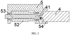
- the drive assembly comprises a worm gear, a third rotating shaft 53 and a motor 4, wherein the worm gear comprises a worm wheel 51 and a worm gear 52 which are fitted with each other;
- the rear side of the connecting base 1 is also fixedly provided with a second limiting member 202 for limiting a rotation range of the unlocking member 3; the second limiting member 202 is located at one side of the unlocking member 3 that is away from a rotation direction of the locking member 2, so as to prevent a failure in a process of the motor 4 driving the second rotating shaft 32 and the unlocking member 3 to rotate through the worm gear, resulting in the locking member 2 rotating too far to go beyond a control range of the unlocking member 3, which can also shorten a reset rotation stroke of the unlocking member 3 and improve the response speed of the locking action of the locking member.
- the rear side of the connecting base 1 is provided with a profiling groove 12 for mounting the thigh support assembly 10, which ensures that the thigh support assembly 10 is firmly connected to the connecting base 1 and avoids a relative rotation of the thigh support assembly 10 on the connecting base 1.
- the rear side of the connecting base 1 is mounted with a back cover 13, which is close to an upper end of the connecting base 1 and fitted with the locking member 2 to form a seal for protecting various parts mounted on the rear side of the connecting base 1 while improving the aesthetic value.
- the front side of the connecting base 1 is mounted with a front cover 14, and the second angle sensor 11 is mounted on the inner side of the front cover 14, which is used for protecting various parts mounted on the front side of the connecting base 1 while improving the aesthetic value.
- the knee joint mechanism without a power source is correspondingly fixed at the thigh, shank and knee joint of the exoskeleton robot, when the legs are in a standing position, the locking member 2 is closely attached to the first limiting member 201, and the unlocking member 3 is closely attached to the other side of the locking member 2; since the unlocking member 3 is connected to the motor rotating shaft 41 through the worm gear, the good self-locking effect is achieved, and the locking member 2 is locked and fixed under the action of the first limiting member 201 and the unlocking member 3.
- the angle between the thigh and shank is locked and fixed through the locking and fixing among the thigh support assembly 10, the connecting base 1 and the shank support assembly 20, thus achieving an effect in supporting the body weight of the patient.
- power is provided at the hip joint of the leg to rotate the thigh support assembly 10; as the thigh support assembly 10 rotates, the first angle sensor on the thigh support assembly 10 senses an angle change signal and controls the motor 4 to rotate, and the motor rotating shaft 41 drives the unlocking member 3 to rotate away from the locking member 2 through the worm gear to unlock the locking block 211.
- the shank support assembly 20 has a certain rotation space between the unlocking member 3 and the first limiting member 201 through the locking member 2, and the patient can complete knee bending and swing.
- the second angle sensor 11 in the connecting base 1 sends a signal, the unlocking member 3 is controlled to reset and rotate in the direction towards the locking member 2 by the motor 4, and the locking member 2 is driven to closely attached to the first limiting member 201, to complete locking again.
- the thigh support assembly 10, the connecting base 1 and the shank support assembly 20 are restored to the original ergonomic angle, to achieve an effect in supporting body weight.
- the other leg can be lifted with such the leg as the support.
- the above cycle completes the walking action and facilitates the patient's lower limb rehabilitation. It is suitable for helping rehabilitation of one leg and helping rehabilitation of both legs at the same time, and its principle of action is the same.
- FIG. 2 is the actual exploded diagram of the structure of the present application
- some unmarked parts are conventional standard parts such as gaskets and jackscrews commonly used in the installation of mechanical structures, and those skilled in the art can select them appropriately according to the actual installation situation, and no explanation will be given in the embodiments.
- the knee joint mechanism herein saves the power source at the knee joint, provides power through the hip, and the angle sensor at the hip or knee joint respectively drives the motor 4 to unlock or lock correspondingly, which achieves a good control effect.
- the overall structure is simpler, the volume is smaller, and the weight is lighter , which greatly improves the endurance thereof.
Landscapes
- Health & Medical Sciences (AREA)
- Epidemiology (AREA)
- Pain & Pain Management (AREA)
- Physical Education & Sports Medicine (AREA)
- Rehabilitation Therapy (AREA)
- Life Sciences & Earth Sciences (AREA)
- Animal Behavior & Ethology (AREA)
- General Health & Medical Sciences (AREA)
- Public Health (AREA)
- Veterinary Medicine (AREA)
- Rehabilitation Tools (AREA)
Applications Claiming Priority (2)
| Application Number | Priority Date | Filing Date | Title |
|---|---|---|---|
| CN202010532163.XA CN111419652B (zh) | 2020-06-12 | 2020-06-12 | 一种无动力源膝关节机构 |
| PCT/CN2021/081744 WO2021248968A1 (zh) | 2020-06-12 | 2021-03-19 | 一种无动力源膝关节机构 |
Publications (3)
| Publication Number | Publication Date |
|---|---|
| EP4134059A1 true EP4134059A1 (de) | 2023-02-15 |
| EP4134059A4 EP4134059A4 (de) | 2024-05-15 |
| EP4134059B1 EP4134059B1 (de) | 2025-01-22 |
Family
ID=71559047
Family Applications (1)
| Application Number | Title | Priority Date | Filing Date |
|---|---|---|---|
| EP21822054.9A Active EP4134059B1 (de) | 2020-06-12 | 2021-03-19 | Kniegelenkmechanismus ohne stromquelle |
Country Status (4)
| Country | Link |
|---|---|
| US (1) | US12558286B2 (de) |
| EP (1) | EP4134059B1 (de) |
| CN (1) | CN111419652B (de) |
| WO (1) | WO2021248968A1 (de) |
Families Citing this family (5)
| Publication number | Priority date | Publication date | Assignee | Title |
|---|---|---|---|---|
| CN111419652B (zh) * | 2020-06-12 | 2020-09-29 | 上海傅利叶智能科技有限公司 | 一种无动力源膝关节机构 |
| CN112891157B (zh) * | 2021-01-21 | 2023-03-28 | 上海傅利叶智能科技有限公司 | 基于智能拐杖的收集数据的方法、装置和智能拐杖 |
| CN115027809A (zh) * | 2022-06-29 | 2022-09-09 | 宁波公牛数码科技有限公司 | 一种盒体结构及无线耳机 |
| CN116292539B (zh) * | 2023-03-24 | 2025-08-01 | 安杰莱科技(杭州)有限公司 | 一种快速拆装锁定机构和下肢康复机器人 |
| CN118991966B (zh) * | 2024-08-16 | 2025-12-12 | 具身智人(北京)科技有限公司 | 人形机器人的下肢系统和人形机器人 |
Family Cites Families (29)
| Publication number | Priority date | Publication date | Assignee | Title |
|---|---|---|---|---|
| US4489718A (en) * | 1983-03-08 | 1984-12-25 | Medical Designs, Inc. | Knee brace hinge |
| CN85107981A (zh) * | 1985-10-28 | 1986-07-02 | 霍满焕 | 步行助力装置 |
| US5399154A (en) * | 1993-06-30 | 1995-03-21 | Empi, Inc. | Constant torque range-of-motion splint |
| US5921946A (en) * | 1997-10-22 | 1999-07-13 | Smith & Nephew, Inc. | Joint brace hinges |
| DE19904554B4 (de) * | 1999-02-04 | 2007-04-26 | Albrecht Gmbh | Zweiseitig wirkende Orthese zur Reduktion von Streck- und/oder Beugedefiziten |
| DE10005764B4 (de) * | 2000-02-10 | 2005-12-15 | Albrecht Gmbh | Orthese mit Verstellung des Flexions- und Extensionsanschlags durch Schienenschwenkbewegungen |
| US6635024B2 (en) * | 2001-05-14 | 2003-10-21 | Bobby Joe Hatton | Articulating knee supports |
| US7235058B2 (en) * | 2002-09-11 | 2007-06-26 | Djo, Llc | Lockable hinge |
| CN2829697Y (zh) * | 2005-09-12 | 2006-10-25 | 唐丹 | 一种膝踝足矫形器线锁膝关节 |
| US7578799B2 (en) * | 2006-06-30 | 2009-08-25 | Ossur Hf | Intelligent orthosis |
| US20100125229A1 (en) * | 2008-07-11 | 2010-05-20 | University Of Delaware | Controllable Joint Brace |
| DE102009052888A1 (de) * | 2009-11-13 | 2011-05-19 | Otto Bock Healthcare Products Gmbh | Verfahren und Vorrichtung zur Steuerung eines künstlichen orthetischen oder prothetischen Gelenkes |
| JP4998623B2 (ja) * | 2010-04-16 | 2012-08-15 | トヨタ自動車株式会社 | 回転制限装置、ロボット関節および歩行補助装具 |
| CN103260576B (zh) * | 2010-12-16 | 2015-04-22 | 丰田自动车株式会社 | 行走辅助装置 |
| CN104822346B (zh) * | 2012-09-07 | 2018-05-11 | 加利福尼亚大学董事会 | 可控被动人工膝部 |
| CN102973337B (zh) * | 2012-09-25 | 2015-05-06 | 电子科技大学 | 一种具有承重自锁功能的主动式膝关节结构 |
| CN203400232U (zh) * | 2013-07-31 | 2014-01-22 | 北京环球精博康复辅具技术有限公司 | 可调型弹性动力膝关节铰链装置 |
| KR102253243B1 (ko) * | 2014-02-18 | 2021-05-20 | 삼성전자주식회사 | 보행 보조장치 및 보행 보조장치의 제어 방법 |
| CN104490568B (zh) * | 2014-12-25 | 2017-02-01 | 北京航空航天大学 | 人体下肢外骨骼助行康复机器人 |
| CN105326627B (zh) * | 2015-11-25 | 2018-04-13 | 华南理工大学 | 基于躯干重心偏移的康复装置行走触发控制方法 |
| JP6148766B1 (ja) | 2016-06-01 | 2017-06-14 | サンコール株式会社 | アクチュエータ付き長下肢装具 |
| EP3357474A1 (de) | 2017-02-07 | 2018-08-08 | Fundación Tecnalia Research & Innovation | Rehabilitationsvorrichtung |
| CN208447860U (zh) * | 2017-09-30 | 2019-02-01 | 北京精博现代假肢矫形器技术有限公司 | 一种膝铰链 |
| CN108652634B (zh) * | 2018-03-29 | 2020-10-09 | 上海理工大学 | 可调仿真膝关节步态数据采集系统及其方法 |
| CN110123589A (zh) | 2019-05-20 | 2019-08-16 | 南京理工大学 | 一种针对偏瘫患者的轻质可穿戴下肢康复助行外骨骼 |
| CN110193819A (zh) | 2019-06-27 | 2019-09-03 | 迈宝智能科技(苏州)有限公司 | 用于可穿戴外骨骼的自适应膝关节机构及装置 |
| CN110465924A (zh) | 2019-08-12 | 2019-11-19 | 山东省科学院自动化研究所 | 一种四连杆膝关节的下肢外骨骼机器人 |
| CN110744526B (zh) | 2019-10-30 | 2020-11-24 | 重庆理工大学 | 一种被动式下肢运动助力外骨骼装置 |
| CN111419652B (zh) * | 2020-06-12 | 2020-09-29 | 上海傅利叶智能科技有限公司 | 一种无动力源膝关节机构 |
-
2020
- 2020-06-12 CN CN202010532163.XA patent/CN111419652B/zh active Active
-
2021
- 2021-03-19 US US17/923,538 patent/US12558286B2/en active Active
- 2021-03-19 WO PCT/CN2021/081744 patent/WO2021248968A1/zh not_active Ceased
- 2021-03-19 EP EP21822054.9A patent/EP4134059B1/de active Active
Also Published As
| Publication number | Publication date |
|---|---|
| CN111419652B (zh) | 2020-09-29 |
| EP4134059A4 (de) | 2024-05-15 |
| US20230181409A1 (en) | 2023-06-15 |
| EP4134059B1 (de) | 2025-01-22 |
| CN111419652A (zh) | 2020-07-17 |
| WO2021248968A1 (zh) | 2021-12-16 |
| US12558286B2 (en) | 2026-02-24 |
Similar Documents
| Publication | Publication Date | Title |
|---|---|---|
| EP4134059A1 (de) | Kniegelenkmechanismus ohne stromquelle | |
| CN102258849B (zh) | 上肢偏瘫康复机器人 | |
| CN107224385B (zh) | 主被动式双臂上肢康复机器人 | |
| CN205795993U (zh) | 康复机器人 | |
| CN111281741A (zh) | 面向不同体型的可重构式外骨骼上肢康复机器人 | |
| CN103735386A (zh) | 穿戴式下肢外骨骼康复机器人 | |
| CN103767815B (zh) | 前置式动力性踝足康复矫形器 | |
| CN110897833A (zh) | 一种开环式可调节腕关节康复训练外骨骼 | |
| CN206577092U (zh) | 一种踝关节康复辅助装置 | |
| CN102697622A (zh) | 坐卧式下肢康复机器人 | |
| CN106667720A (zh) | 穿戴式下肢外骨骼康复机器人髋关节弹簧电机并联驱动器 | |
| CN109966117A (zh) | 一种被动式可穿戴助行机器人 | |
| CN112022631A (zh) | 一种多体位康复训练下肢外骨骼装置 | |
| CN112741756A (zh) | 一种自调节式手腕康复机器人 | |
| CN115701796A (zh) | 一种用于人体下肢外骨骼、假肢、矫形器的智能膝关节 | |
| CN113545958A (zh) | 一种肩关节康复机器人 | |
| CN110613584B (zh) | 一种柔性下肢康复训练机构 | |
| CN107361999B (zh) | 一种行走式肩关节康复训练机构 | |
| CN113967151A (zh) | 一种基于重力补偿的主动上肢康复装置 | |
| CN207139796U (zh) | 髋关节助力机构及下肢外骨骼 | |
| CN215132743U (zh) | 一种多运动轴膝关节外骨骼结构 | |
| CN107569362B (zh) | 一种外骨骼机器人及其髋关节部件 | |
| CN109363811A (zh) | 一种基于轮椅的上肢外骨骼机器人 | |
| CN210812298U (zh) | 一种六自由度可穿戴柔性绳驱外骨骼式上肢康复训练机器人 | |
| CN212592982U (zh) | 一种面向肩关节康复的辅助装备 |
Legal Events
| Date | Code | Title | Description |
|---|---|---|---|
| STAA | Information on the status of an ep patent application or granted ep patent |
Free format text: STATUS: THE INTERNATIONAL PUBLICATION HAS BEEN MADE |
|
| PUAI | Public reference made under article 153(3) epc to a published international application that has entered the european phase |
Free format text: ORIGINAL CODE: 0009012 |
|
| STAA | Information on the status of an ep patent application or granted ep patent |
Free format text: STATUS: REQUEST FOR EXAMINATION WAS MADE |
|
| 17P | Request for examination filed |
Effective date: 20221108 |
|
| AK | Designated contracting states |
Kind code of ref document: A1 Designated state(s): AL AT BE BG CH CY CZ DE DK EE ES FI FR GB GR HR HU IE IS IT LI LT LU LV MC MK MT NL NO PL PT RO RS SE SI SK SM TR |
|
| DAV | Request for validation of the european patent (deleted) | ||
| DAX | Request for extension of the european patent (deleted) | ||
| A4 | Supplementary search report drawn up and despatched |
Effective date: 20240411 |
|
| RIC1 | Information provided on ipc code assigned before grant |
Ipc: A61H 1/02 20060101ALI20240405BHEP Ipc: A61H 3/00 20060101AFI20240405BHEP |
|
| GRAP | Despatch of communication of intention to grant a patent |
Free format text: ORIGINAL CODE: EPIDOSNIGR1 |
|
| STAA | Information on the status of an ep patent application or granted ep patent |
Free format text: STATUS: GRANT OF PATENT IS INTENDED |
|
| INTG | Intention to grant announced |
Effective date: 20240816 |
|
| GRAS | Grant fee paid |
Free format text: ORIGINAL CODE: EPIDOSNIGR3 |
|
| GRAA | (expected) grant |
Free format text: ORIGINAL CODE: 0009210 |
|
| STAA | Information on the status of an ep patent application or granted ep patent |
Free format text: STATUS: THE PATENT HAS BEEN GRANTED |
|
| P01 | Opt-out of the competence of the unified patent court (upc) registered |
Free format text: CASE NUMBER: APP_64642/2024 Effective date: 20241206 |
|
| AK | Designated contracting states |
Kind code of ref document: B1 Designated state(s): AL AT BE BG CH CY CZ DE DK EE ES FI FR GB GR HR HU IE IS IT LI LT LU LV MC MK MT NL NO PL PT RO RS SE SI SK SM TR |
|
| REG | Reference to a national code |
Ref country code: GB Ref legal event code: FG4D |
|
| REG | Reference to a national code |
Ref country code: CH Ref legal event code: EP |
|
| REG | Reference to a national code |
Ref country code: IE Ref legal event code: FG4D |
|
| REG | Reference to a national code |
Ref country code: DE Ref legal event code: R096 Ref document number: 602021025194 Country of ref document: DE |
|
| PGFP | Annual fee paid to national office [announced via postgrant information from national office to epo] |
Ref country code: AT Payment date: 20250417 Year of fee payment: 5 |
|
| REG | Reference to a national code |
Ref country code: NL Ref legal event code: MP Effective date: 20250122 |
|
| PG25 | Lapsed in a contracting state [announced via postgrant information from national office to epo] |
Ref country code: NL Free format text: LAPSE BECAUSE OF FAILURE TO SUBMIT A TRANSLATION OF THE DESCRIPTION OR TO PAY THE FEE WITHIN THE PRESCRIBED TIME-LIMIT Effective date: 20250122 |
|
| PG25 | Lapsed in a contracting state [announced via postgrant information from national office to epo] |
Ref country code: RS Free format text: LAPSE BECAUSE OF FAILURE TO SUBMIT A TRANSLATION OF THE DESCRIPTION OR TO PAY THE FEE WITHIN THE PRESCRIBED TIME-LIMIT Effective date: 20250422 |
|
| PG25 | Lapsed in a contracting state [announced via postgrant information from national office to epo] |
Ref country code: FI Free format text: LAPSE BECAUSE OF FAILURE TO SUBMIT A TRANSLATION OF THE DESCRIPTION OR TO PAY THE FEE WITHIN THE PRESCRIBED TIME-LIMIT Effective date: 20250122 |
|
| PG25 | Lapsed in a contracting state [announced via postgrant information from national office to epo] |
Ref country code: PL Free format text: LAPSE BECAUSE OF FAILURE TO SUBMIT A TRANSLATION OF THE DESCRIPTION OR TO PAY THE FEE WITHIN THE PRESCRIBED TIME-LIMIT Effective date: 20250122 |
|
| PG25 | Lapsed in a contracting state [announced via postgrant information from national office to epo] |
Ref country code: ES Free format text: LAPSE BECAUSE OF FAILURE TO SUBMIT A TRANSLATION OF THE DESCRIPTION OR TO PAY THE FEE WITHIN THE PRESCRIBED TIME-LIMIT Effective date: 20250122 |
|
| REG | Reference to a national code |
Ref country code: LT Ref legal event code: MG9D |
|
| PG25 | Lapsed in a contracting state [announced via postgrant information from national office to epo] |
Ref country code: NO Free format text: LAPSE BECAUSE OF FAILURE TO SUBMIT A TRANSLATION OF THE DESCRIPTION OR TO PAY THE FEE WITHIN THE PRESCRIBED TIME-LIMIT Effective date: 20250422 Ref country code: IS Free format text: LAPSE BECAUSE OF FAILURE TO SUBMIT A TRANSLATION OF THE DESCRIPTION OR TO PAY THE FEE WITHIN THE PRESCRIBED TIME-LIMIT Effective date: 20250522 |
|
| REG | Reference to a national code |
Ref country code: AT Ref legal event code: MK05 Ref document number: 1760944 Country of ref document: AT Kind code of ref document: T Effective date: 20250122 |
|
| PG25 | Lapsed in a contracting state [announced via postgrant information from national office to epo] |
Ref country code: HR Free format text: LAPSE BECAUSE OF FAILURE TO SUBMIT A TRANSLATION OF THE DESCRIPTION OR TO PAY THE FEE WITHIN THE PRESCRIBED TIME-LIMIT Effective date: 20250122 |
|
| PG25 | Lapsed in a contracting state [announced via postgrant information from national office to epo] |
Ref country code: PT Free format text: LAPSE BECAUSE OF FAILURE TO SUBMIT A TRANSLATION OF THE DESCRIPTION OR TO PAY THE FEE WITHIN THE PRESCRIBED TIME-LIMIT Effective date: 20250522 Ref country code: LV Free format text: LAPSE BECAUSE OF FAILURE TO SUBMIT A TRANSLATION OF THE DESCRIPTION OR TO PAY THE FEE WITHIN THE PRESCRIBED TIME-LIMIT Effective date: 20250122 |
|
| PG25 | Lapsed in a contracting state [announced via postgrant information from national office to epo] |
Ref country code: BG Free format text: LAPSE BECAUSE OF FAILURE TO SUBMIT A TRANSLATION OF THE DESCRIPTION OR TO PAY THE FEE WITHIN THE PRESCRIBED TIME-LIMIT Effective date: 20250122 Ref country code: GR Free format text: LAPSE BECAUSE OF FAILURE TO SUBMIT A TRANSLATION OF THE DESCRIPTION OR TO PAY THE FEE WITHIN THE PRESCRIBED TIME-LIMIT Effective date: 20250423 |
|
| PG25 | Lapsed in a contracting state [announced via postgrant information from national office to epo] |
Ref country code: AT Free format text: LAPSE BECAUSE OF FAILURE TO SUBMIT A TRANSLATION OF THE DESCRIPTION OR TO PAY THE FEE WITHIN THE PRESCRIBED TIME-LIMIT Effective date: 20250122 |
|
| PG25 | Lapsed in a contracting state [announced via postgrant information from national office to epo] |
Ref country code: SE Free format text: LAPSE BECAUSE OF FAILURE TO SUBMIT A TRANSLATION OF THE DESCRIPTION OR TO PAY THE FEE WITHIN THE PRESCRIBED TIME-LIMIT Effective date: 20250122 |
|
| PG25 | Lapsed in a contracting state [announced via postgrant information from national office to epo] |
Ref country code: SM Free format text: LAPSE BECAUSE OF FAILURE TO SUBMIT A TRANSLATION OF THE DESCRIPTION OR TO PAY THE FEE WITHIN THE PRESCRIBED TIME-LIMIT Effective date: 20250122 |
|
| PG25 | Lapsed in a contracting state [announced via postgrant information from national office to epo] |
Ref country code: DK Free format text: LAPSE BECAUSE OF FAILURE TO SUBMIT A TRANSLATION OF THE DESCRIPTION OR TO PAY THE FEE WITHIN THE PRESCRIBED TIME-LIMIT Effective date: 20250122 |
|
| PG25 | Lapsed in a contracting state [announced via postgrant information from national office to epo] |
Ref country code: MC Free format text: LAPSE BECAUSE OF FAILURE TO SUBMIT A TRANSLATION OF THE DESCRIPTION OR TO PAY THE FEE WITHIN THE PRESCRIBED TIME-LIMIT Effective date: 20250122 |
|
| PG25 | Lapsed in a contracting state [announced via postgrant information from national office to epo] |
Ref country code: IT Free format text: LAPSE BECAUSE OF FAILURE TO SUBMIT A TRANSLATION OF THE DESCRIPTION OR TO PAY THE FEE WITHIN THE PRESCRIBED TIME-LIMIT Effective date: 20250122 |
|
| PG25 | Lapsed in a contracting state [announced via postgrant information from national office to epo] |
Ref country code: CZ Free format text: LAPSE BECAUSE OF FAILURE TO SUBMIT A TRANSLATION OF THE DESCRIPTION OR TO PAY THE FEE WITHIN THE PRESCRIBED TIME-LIMIT Effective date: 20250122 Ref country code: EE Free format text: LAPSE BECAUSE OF FAILURE TO SUBMIT A TRANSLATION OF THE DESCRIPTION OR TO PAY THE FEE WITHIN THE PRESCRIBED TIME-LIMIT Effective date: 20250122 |
|
| REG | Reference to a national code |
Ref country code: CH Ref legal event code: H13 Free format text: ST27 STATUS EVENT CODE: U-0-0-H10-H13 (AS PROVIDED BY THE NATIONAL OFFICE) Effective date: 20251023 Ref country code: DE Ref legal event code: R097 Ref document number: 602021025194 Country of ref document: DE |
|
| PG25 | Lapsed in a contracting state [announced via postgrant information from national office to epo] |
Ref country code: RO Free format text: LAPSE BECAUSE OF FAILURE TO SUBMIT A TRANSLATION OF THE DESCRIPTION OR TO PAY THE FEE WITHIN THE PRESCRIBED TIME-LIMIT Effective date: 20250122 |
|
| PG25 | Lapsed in a contracting state [announced via postgrant information from national office to epo] |
Ref country code: SK Free format text: LAPSE BECAUSE OF FAILURE TO SUBMIT A TRANSLATION OF THE DESCRIPTION OR TO PAY THE FEE WITHIN THE PRESCRIBED TIME-LIMIT Effective date: 20250122 |
|
| PG25 | Lapsed in a contracting state [announced via postgrant information from national office to epo] |
Ref country code: LU Free format text: LAPSE BECAUSE OF NON-PAYMENT OF DUE FEES Effective date: 20250319 |
|
| PLBE | No opposition filed within time limit |
Free format text: ORIGINAL CODE: 0009261 |
|
| STAA | Information on the status of an ep patent application or granted ep patent |
Free format text: STATUS: NO OPPOSITION FILED WITHIN TIME LIMIT |
|
| REG | Reference to a national code |
Ref country code: BE Ref legal event code: MM Effective date: 20250331 |
|
| 26N | No opposition filed |
Effective date: 20251023 |
|
| PG25 | Lapsed in a contracting state [announced via postgrant information from national office to epo] |
Ref country code: BE Free format text: LAPSE BECAUSE OF NON-PAYMENT OF DUE FEES Effective date: 20250331 |
|
| PG25 | Lapsed in a contracting state [announced via postgrant information from national office to epo] |
Ref country code: CH Free format text: LAPSE BECAUSE OF NON-PAYMENT OF DUE FEES Effective date: 20250331 |
|
| PG25 | Lapsed in a contracting state [announced via postgrant information from national office to epo] |
Ref country code: IE Free format text: LAPSE BECAUSE OF NON-PAYMENT OF DUE FEES Effective date: 20250319 |
|
| PGFP | Annual fee paid to national office [announced via postgrant information from national office to epo] |
Ref country code: GB Payment date: 20260325 Year of fee payment: 6 |
|
| PGFP | Annual fee paid to national office [announced via postgrant information from national office to epo] |
Ref country code: DE Payment date: 20260324 Year of fee payment: 6 |
|
| PGFP | Annual fee paid to national office [announced via postgrant information from national office to epo] |
Ref country code: FR Payment date: 20260330 Year of fee payment: 6 |