EP4133166B1 - Adapteranordnung und bauteilverbund - Google Patents
Adapteranordnung und bauteilverbund Download PDFInfo
- Publication number
- EP4133166B1 EP4133166B1 EP21717309.5A EP21717309A EP4133166B1 EP 4133166 B1 EP4133166 B1 EP 4133166B1 EP 21717309 A EP21717309 A EP 21717309A EP 4133166 B1 EP4133166 B1 EP 4133166B1
- Authority
- EP
- European Patent Office
- Prior art keywords
- current
- housing
- connection
- connecting component
- gas container
- Prior art date
- Legal status (The legal status is an assumption and is not a legal conclusion. Google has not performed a legal analysis and makes no representation as to the accuracy of the status listed.)
- Active
Links
Images


Classifications
-
- F—MECHANICAL ENGINEERING; LIGHTING; HEATING; WEAPONS; BLASTING
- F01—MACHINES OR ENGINES IN GENERAL; ENGINE PLANTS IN GENERAL; STEAM ENGINES
- F01N—GAS-FLOW SILENCERS OR EXHAUST APPARATUS FOR MACHINES OR ENGINES IN GENERAL; GAS-FLOW SILENCERS OR EXHAUST APPARATUS FOR INTERNAL-COMBUSTION ENGINES
- F01N3/00—Exhaust or silencing apparatus having means for purifying, rendering innocuous, or otherwise treating exhaust
- F01N3/08—Exhaust or silencing apparatus having means for purifying, rendering innocuous, or otherwise treating exhaust for rendering innocuous
- F01N3/10—Exhaust or silencing apparatus having means for purifying, rendering innocuous, or otherwise treating exhaust for rendering innocuous by thermal or catalytic conversion of noxious components of exhaust
- F01N3/18—Exhaust or silencing apparatus having means for purifying, rendering innocuous, or otherwise treating exhaust for rendering innocuous by thermal or catalytic conversion of noxious components of exhaust characterised by methods of operation; Control
- F01N3/20—Exhaust or silencing apparatus having means for purifying, rendering innocuous, or otherwise treating exhaust for rendering innocuous by thermal or catalytic conversion of noxious components of exhaust characterised by methods of operation; Control specially adapted for catalytic conversion
- F01N3/2006—Periodically heating or cooling catalytic reactors, e.g. at cold starting or overheating
- F01N3/2013—Periodically heating or cooling catalytic reactors, e.g. at cold starting or overheating using electric or magnetic heating means
- F01N3/2026—Periodically heating or cooling catalytic reactors, e.g. at cold starting or overheating using electric or magnetic heating means directly electrifying the catalyst substrate, i.e. heating the electrically conductive catalyst substrate by joule effect
-
- H—ELECTRICITY
- H01—ELECTRIC ELEMENTS
- H01B—CABLES; CONDUCTORS; INSULATORS; SELECTION OF MATERIALS FOR THEIR CONDUCTIVE, INSULATING OR DIELECTRIC PROPERTIES
- H01B17/00—Insulators or insulating bodies characterised by their form
- H01B17/26—Lead-in insulators; Lead-through insulators
- H01B17/30—Sealing
- H01B17/303—Sealing of leads to lead-through insulators
- H01B17/306—Sealing of leads to lead-through insulators by embedding in material other than glass or ceramics
-
- F—MECHANICAL ENGINEERING; LIGHTING; HEATING; WEAPONS; BLASTING
- F01—MACHINES OR ENGINES IN GENERAL; ENGINE PLANTS IN GENERAL; STEAM ENGINES
- F01N—GAS-FLOW SILENCERS OR EXHAUST APPARATUS FOR MACHINES OR ENGINES IN GENERAL; GAS-FLOW SILENCERS OR EXHAUST APPARATUS FOR INTERNAL-COMBUSTION ENGINES
- F01N3/00—Exhaust or silencing apparatus having means for purifying, rendering innocuous, or otherwise treating exhaust
- F01N3/08—Exhaust or silencing apparatus having means for purifying, rendering innocuous, or otherwise treating exhaust for rendering innocuous
- F01N3/10—Exhaust or silencing apparatus having means for purifying, rendering innocuous, or otherwise treating exhaust for rendering innocuous by thermal or catalytic conversion of noxious components of exhaust
- F01N3/24—Exhaust or silencing apparatus having means for purifying, rendering innocuous, or otherwise treating exhaust for rendering innocuous by thermal or catalytic conversion of noxious components of exhaust characterised by constructional aspects of converting apparatus
- F01N3/28—Construction of catalytic reactors
- F01N3/2803—Construction of catalytic reactors characterised by structure, by material or by manufacturing of catalyst support
- F01N3/2807—Metal other than sintered metal
- F01N3/281—Metallic honeycomb monoliths made of stacked or rolled sheets, foils or plates
-
- H—ELECTRICITY
- H01—ELECTRIC ELEMENTS
- H01R—ELECTRICALLY-CONDUCTIVE CONNECTIONS; STRUCTURAL ASSOCIATIONS OF A PLURALITY OF MUTUALLY-INSULATED ELECTRICAL CONNECTING ELEMENTS; COUPLING DEVICES; CURRENT COLLECTORS
- H01R13/00—Details of coupling devices of the kinds covered by groups H01R12/70 or H01R24/00 - H01R33/00
- H01R13/46—Bases; Cases
- H01R13/52—Dustproof, splashproof, drip-proof, waterproof, or flameproof cases
- H01R13/521—Sealing between contact members and housing, e.g. sealing insert
-
- H—ELECTRICITY
- H02—GENERATION; CONVERSION OR DISTRIBUTION OF ELECTRIC POWER
- H02G—INSTALLATION OF ELECTRIC CABLES OR LINES, OR OF COMBINED OPTICAL AND ELECTRIC CABLES OR LINES
- H02G3/00—Installations of electric cables or lines or protective tubing therefor in or on buildings, equivalent structures or vehicles
- H02G3/02—Details
- H02G3/06—Joints for connecting lengths of protective tubing or channels, to each other or to casings, e.g. to distribution boxes; Ensuring electrical continuity in the joint
- H02G3/0616—Joints for connecting tubing to casing
-
- F—MECHANICAL ENGINEERING; LIGHTING; HEATING; WEAPONS; BLASTING
- F01—MACHINES OR ENGINES IN GENERAL; ENGINE PLANTS IN GENERAL; STEAM ENGINES
- F01N—GAS-FLOW SILENCERS OR EXHAUST APPARATUS FOR MACHINES OR ENGINES IN GENERAL; GAS-FLOW SILENCERS OR EXHAUST APPARATUS FOR INTERNAL-COMBUSTION ENGINES
- F01N2240/00—Combination or association of two or more different exhaust treating devices, or of at least one such device with an auxiliary device, not covered by indexing codes F01N2230/00 or F01N2250/00, one of the devices being
- F01N2240/32—Combination or association of two or more different exhaust treating devices, or of at least one such device with an auxiliary device, not covered by indexing codes F01N2230/00 or F01N2250/00, one of the devices being a fuel cell
-
- F—MECHANICAL ENGINEERING; LIGHTING; HEATING; WEAPONS; BLASTING
- F01—MACHINES OR ENGINES IN GENERAL; ENGINE PLANTS IN GENERAL; STEAM ENGINES
- F01N—GAS-FLOW SILENCERS OR EXHAUST APPARATUS FOR MACHINES OR ENGINES IN GENERAL; GAS-FLOW SILENCERS OR EXHAUST APPARATUS FOR INTERNAL-COMBUSTION ENGINES
- F01N2330/00—Structure of catalyst support or particle filter
- F01N2330/02—Metallic plates or honeycombs, e.g. superposed or rolled-up corrugated or otherwise deformed sheet metal
-
- H—ELECTRICITY
- H01—ELECTRIC ELEMENTS
- H01J—ELECTRIC DISCHARGE TUBES OR DISCHARGE LAMPS
- H01J5/00—Details relating to vessels or to leading-in conductors common to two or more basic types of discharge tubes or lamps
- H01J5/20—Seals between parts of vessels
- H01J5/22—Vacuum-tight joints between parts of vessel
-
- H—ELECTRICITY
- H01—ELECTRIC ELEMENTS
- H01R—ELECTRICALLY-CONDUCTIVE CONNECTIONS; STRUCTURAL ASSOCIATIONS OF A PLURALITY OF MUTUALLY-INSULATED ELECTRICAL CONNECTING ELEMENTS; COUPLING DEVICES; CURRENT COLLECTORS
- H01R2201/00—Connectors or connections adapted for particular applications
- H01R2201/26—Connectors or connections adapted for particular applications for vehicles
-
- H—ELECTRICITY
- H02—GENERATION; CONVERSION OR DISTRIBUTION OF ELECTRIC POWER
- H02G—INSTALLATION OF ELECTRIC CABLES OR LINES, OR OF COMBINED OPTICAL AND ELECTRIC CABLES OR LINES
- H02G3/00—Installations of electric cables or lines or protective tubing therefor in or on buildings, equivalent structures or vehicles
- H02G3/22—Installations of cables or lines through walls, floors or ceilings, e.g. into buildings
-
- H—ELECTRICITY
- H05—ELECTRIC TECHNIQUES NOT OTHERWISE PROVIDED FOR
- H05B—ELECTRIC HEATING; ELECTRIC LIGHT SOURCES NOT OTHERWISE PROVIDED FOR; CIRCUIT ARRANGEMENTS FOR ELECTRIC LIGHT SOURCES, IN GENERAL
- H05B3/00—Ohmic-resistance heating
- H05B3/02—Details
- H05B3/06—Heater elements structurally combined with coupling elements or holders
-
- H—ELECTRICITY
- H10—SEMICONDUCTOR DEVICES; ELECTRIC SOLID-STATE DEVICES NOT OTHERWISE PROVIDED FOR
- H10W—GENERIC PACKAGES, INTERCONNECTIONS, CONNECTORS OR OTHER CONSTRUCTIONAL DETAILS OF DEVICES COVERED BY CLASS H10
- H10W95/00—Packaging processes not covered by the other groups of this subclass
-
- Y—GENERAL TAGGING OF NEW TECHNOLOGICAL DEVELOPMENTS; GENERAL TAGGING OF CROSS-SECTIONAL TECHNOLOGIES SPANNING OVER SEVERAL SECTIONS OF THE IPC; TECHNICAL SUBJECTS COVERED BY FORMER USPC CROSS-REFERENCE ART COLLECTIONS [XRACs] AND DIGESTS
- Y02—TECHNOLOGIES OR APPLICATIONS FOR MITIGATION OR ADAPTATION AGAINST CLIMATE CHANGE
- Y02E—REDUCTION OF GREENHOUSE GAS [GHG] EMISSIONS, RELATED TO ENERGY GENERATION, TRANSMISSION OR DISTRIBUTION
- Y02E60/00—Enabling technologies; Technologies with a potential or indirect contribution to GHG emissions mitigation
- Y02E60/30—Hydrogen technology
- Y02E60/50—Fuel cells
-
- Y—GENERAL TAGGING OF NEW TECHNOLOGICAL DEVELOPMENTS; GENERAL TAGGING OF CROSS-SECTIONAL TECHNOLOGIES SPANNING OVER SEVERAL SECTIONS OF THE IPC; TECHNICAL SUBJECTS COVERED BY FORMER USPC CROSS-REFERENCE ART COLLECTIONS [XRACs] AND DIGESTS
- Y02—TECHNOLOGIES OR APPLICATIONS FOR MITIGATION OR ADAPTATION AGAINST CLIMATE CHANGE
- Y02T—CLIMATE CHANGE MITIGATION TECHNOLOGIES RELATED TO TRANSPORTATION
- Y02T10/00—Road transport of goods or passengers
- Y02T10/10—Internal combustion engine [ICE] based vehicles
- Y02T10/12—Improving ICE efficiencies
Definitions
- the present invention relates to an adapter arrangement for the gas-tight conduction of electrical current into a gas container. Furthermore, the invention relates to a component assembly with a gas container and an adapter arrangement for supporting a current-tight conduction of electrical current into the gas container.
- an electrical heating device for the start-up operation of a fuel cell system in order to bring the fuel cell system, in particular a fuel cell stack of the fuel cell system, to the desired operating temperature as quickly as possible.
- Electrically heatable metal catalysts are known as heating devices. These have a catalyst housing in which there is catalyst material that can be quickly brought to a desired operating temperature by an electrically operated auxiliary device. The current for the auxiliary device positioned in the catalyst housing is fed into the catalyst housing through a power connection that protrudes beyond the catalyst housing.
- JP H07 208154 A , JP H07 259543 A , JP H09 032533 A , DE 1 127 422 A and DE 196 27 840 A1 each disclose an arrangement with a gas-tight electrical feedthrough through a wall section.
- the object of the present invention is to at least partially take into account the problems described above.
- the object of the present invention is to create an aid for the gas-tight conduction of electrical current into a gas container, in particular in the form of a metal catalyst as described in the introduction.
- the gas container can be understood as a catalyst housing of an electrically heatable catalyst, in particular a metal catalyst such as an Emicat.
- the adapter arrangement according to the invention can be implemented using simple means.
- simple geometric bodies such as a simple hollow cylinder for the housing, can be used to implement the adapter arrangement. This means that the adapter arrangement can be manufactured quickly and inexpensively. Furthermore, the adapter arrangement can be implemented in a relatively small installation space.
- the housing can have a housing shell section which extends at least partially around the power connection in a shell-like manner.
- the housing shell section is preferably cylindrical and/or tubular.
- the fact that the housing at least partially encloses the power connection can be understood to mean that the housing and/or the housing shell section only extends around a part of the power connection in the longitudinal direction of the power connection.
- the fact that the housing is designed to at least partially enclose the power connection in a circumferential direction of the power connection can be understood to mean that the housing surrounds the power connection in a shell-like manner in a longitudinal direction of the power connection.
- the cover viewed separately from a housing shell section as described above, is preferably configured in the shape of a disk and/or a plate with a through-opening preferably formed centrally therein.
- the housing shell section and the cover can be provided as components that are integrally connected to one another at at least one point. This can simplify the attachment of the adapter arrangement to the gas container.
- Contact-free removal of the power connection from the housing means removing the power connection from the housing without direct mechanical contact between the power connection and the housing. Since the power connection and the housing are preferably made of metal and/or an electrically conductive material, this can prevent a short circuit and/or other electrical malfunction.
- a diameter and/or a dimension of the through-opening are selected to be larger than the diameter and/or the dimension of an existing and/or desired power connection in the area of the through-opening.
- the container sealant can be understood as a means for materially connecting the housing to the gas container.
- the container sealant preferably has a weld seam through which the housing can be attached to the gas container, in particular at least to the outer surface of the gas container.
- the container sealant is preferably provided in order to make the area in which the housing is attached to the gas container gas-tight. This means that the container sealant does not have to seal the entire container against gas leakage.
- the bearing means serves to fix the first insulating means in the desired position.
- the bearing means can therefore be understood as a counter bearing to the cover, more precisely to an inner side of the cover that faces into an inner volume of the housing.
- the bearing means can be positioned directly on the first insulating means, preferably with direct surface contact between the bearing means and the first insulating means.
- Sealing the gap can be understood as a gas-tight closure of at least one gap between the power connection and the cover, which arises when the power connection is led out of the housing through the through-opening without contact.
- the housing sealant is preferably configured to prevent gas from escaping from the housing. The prevention of gas escaping can be achieved directly or indirectly.
- the housing sealant can thus seal the gap in a gas-tight manner directly or with aids such as the second insulating means.
- the first insulating means and the second insulating means can each have a disk-shaped insulating ring or can be designed as a disk-shaped insulating ring for annular arrangement around the power connection.
- the first insulating means and/or the second insulating means can each be designed to seal the container against gas escaping from the housing.
- the first insulating means and/or the second insulating means can consist of elastic plastic or have a corresponding elastic plastic.
- the first sealing means and/or the second sealing means are preferably each designed as one piece.
- the insulating means can also consist of a dimensionally stable, electrically non-conductive material, for example ceramic, or at least have this material for the electrical insulating function.
- the power connection in an adapter arrangement to have a first power connection threaded section and for the bearing means to have at least one nut for screwing onto the first threaded section.
- the bearing means preferably has two nuts, with one nut serving as a lock nut. Screwing on can be understood as screwing on, screwing in or turning on.
- the threaded section can therefore have an external thread or an internal thread.
- the first power connection threaded section is preferably designed as an internal thread on an inner circumferential surface of the bearing means and/or the at least one nut or has an internal thread that can be screwed onto a corresponding external thread of the power connection.
- an adapter arrangement for the power connection to have a second power connection threaded section and for the housing sealing means to have at least one nut for screwing onto the second threaded section.
- the at least one nut of the housing sealing means can, for example, be screwed onto the second insulating means until a gas-tight closure for sealing the housing is produced.
- the housing sealing means can have a further nut which can be screwed onto the second power connection threaded section as a lock nut to fix the first nut of the housing sealing means.
- an adapter arrangement according to the invention has a clamping means which is arranged at least partially between the bearing means and the first insulating means in order to apply pressure to the first insulating means in the direction of the cover.
- the clamping means can have a one-piece spring element.
- the clamping means is preferably designed in a ring shape for sliding onto the power connection.
- An adapter arrangement according to the invention can also have at least one ring-shaped washer for positioning between the bearing means and the first insulating means, between the housing sealing means and the second insulating means and/or between the bearing means and the clamping means and/or between the clamping means and the first insulating means. This allows the forces to be transferred to the respective components in a simple, reliable and effective manner in a cost-effective and safe manner.
- a ring shape is preferably understood to mean a shape that is formed by two shell sections that are arranged concentrically to one another and have a circular cross-section.
- an outer peripheral surface and/or an inner peripheral surface of a ring shape according to the invention can also be designed to be elliptical and/or angular, for example hexagonal like a nut.
- the insulating means are each preferably disc-shaped, i.e. with a flat or substantially flat upper side and a flat lower side.
- an adapter arrangement it is possible for an adapter arrangement to have an elastically deformable first current conducting means with a current conducting means fastening section for fastening the first current conducting means outside the housing to the power connection in order to tap power from the power connection via the first current conducting means.
- the first current conducting means can compensate for thermally induced size differences of the gas container, the power connection and/or the housing in a simple and cost-effective manner.
- the current conducting means fastening section preferably has a current conducting means threaded section, in particular an internal thread in and/or on the current conducting means, for screwing the current conducting means onto the power connection.
- the first current conducting means is preferably plate-shaped or substantially plate-shaped. This means that a length and a width of the current conducting means are each several times longer and/or higher than a height of the current conducting means.
- the current conducting means preferably has a flat or substantially flat upper side and a flat or substantially flat lower side.
- the current conducting means can be cuboid-shaped or substantially cuboid-shaped, in particular with respect to the outer contour of the current conducting means.
- an adapter arrangement according to the present invention can have a fixing means for non-destructively releasably fixing the first current conducting means to the power connection at least partially between the fixing means and the housing sealing means.
- the fixing means makes assembly and disassembly in the event of maintenance and/or repair particularly easy.
- the power connection has a second power connection threaded section and the fixing means has at least one nut for screwing onto the second power connection threaded section.
- the adapter arrangement according to this aspect essentially corresponds to the embodiment according to the first aspect, wherein the housing is not sealed around the power connection, but around the connecting component.
- This has the advantage that the adapter arrangement can be used and/or mounted even more easily and/or flexibly on different gas containers and/or power connections.
- the connecting component in an adapter arrangement according to the second aspect, it is possible for the connecting component to have a first connecting component threaded section and for the bearing means to have at least one nut for screwing onto the first threaded section. It is also possible for the connecting component to have a second connecting component threaded section and for the housing sealing means to have at least one nut for screwing onto the second connecting component threaded section.
- the adapter arrangement with connecting component also has a clamping means which is arranged at least partially between the bearing means and the first insulating means for applying pressure to the first insulating means in the direction of the cover.
- the elastically deformable first current conducting means can have the current conducting means fastening section for fastening the first current conducting means outside the housing to the connecting component for tapping current from the connecting component via the first current conducting means.
- the fixing means can be configured for non-destructively releasable fixing of the first current conducting means to the connecting component at least partially between the fixing means and the housing sealing means.
- the connecting component in an adapter arrangement according to the second aspect, it is possible for the connecting component to have a second connecting component threaded section and for the fixing means to have at least one nut for screwing onto the second connecting component threaded section.
- the connecting component fastening section can have a third connecting component threaded section for screwing the connecting component onto a corresponding power connection threaded section of the power connection. This allows the connecting component to be connected to the power connection quickly, easily and reliably.
- the third connecting component threaded section preferably has an internal thread that can be screwed onto a corresponding external thread of the power connection.
- the connecting component in an adapter arrangement according to the second aspect is designed in one piece, in particular in the shape of a pin and/or a tenon.
- the adapter arrangement can thus be made particularly stable, space-saving and cost-effective.
- the connecting component in an adapter arrangement according to the present invention has a fourth connecting component threaded portion on an end face of the connecting component for a screw connection between a further power connection and the connecting component.
- an adapter arrangement can have an elastically deformable second current conducting means, wherein the power connection and the connecting component are mechanically connected to one another by the second current conducting means for an electrical connection between the power connection and the connecting component.
- the second current conducting means can compensate for thermally induced size differences of the gas container, the power connection, the connecting component and/or the housing in a simple and cost-effective manner.
- the second current conducting means preferably has a first current conducting means threaded section and/or a second current conducting means threaded section, each of which has in particular an internal thread in and/or on the second current conducting means.
- the threaded sections allow the second current conducting means to be easily connected to the power connection and/or the connecting component to establish the desired electrical connection between the power connection, the second current conducting means and the connecting component.
- the second current conducting means is preferably designed in the form of a plate or substantially in the form of a plate.
- the second current conducting means preferably has a flat or substantially flat upper side and a flat or substantially flat lower side.
- the current conducting means can be designed in the form of a cuboid or substantially in the form of a cuboid, particularly with respect to the outer contour of the current conducting means.
- a component assembly is provided.
- the component assembly has a gas container with an outer surface and a projection-like power connection, wherein the power connection extends from an inner volume of the gas container beyond the outer surface of the gas container for conducting an electrical current into the gas container.
- the component assembly also has an adapter arrangement attached to the outer surface and to the power connection and as described in detail above.
- the power connection is preferably designed in the form of a pin and/or a peg.
- Fig.1 shows an adapter arrangement 10a for gas-tight conduction of electrical current into a gas container 11 according to a first embodiment.
- the gas container 11 has a pin-shaped, projection-like power connection 12 which extends from an inner volume 40 of the gas container 11 beyond an outer surface 13 of the gas container 11 for conducting the electrical current into the gas container 11.
- the adapter arrangement 10a has a housing 14 for enclosing the power connection 12 in a circumferential direction of the power connection 12 in the region in which the power connection 12 protrudes from the gas container 11.
- the housing 14 has a cover 15 with a through-opening 16 for contact-free removal of the power connection 12 from the housing 14.
- the adapter arrangement 10a further comprises a container sealing means 18 in the form of a weld seam for gas-tight fastening of the housing 14 to the gas container 11. This means that the housing 14 is firmly connected to the gas container 11 by the weld seam of the container sealing means 18.
- the adapter arrangement 10a comprises a bearing means 19 fastened to the power connection 12 within the housing 14.
- the Fig.1 The illustrated bearing means 19 has a first nut 24 and a lock nut 25, each of which is screwed onto a corresponding threaded portion of the power connector 12.
- the illustrated adapter arrangement 10a has a first insulating means 20, which is positioned between the bearing means 19 and the cover 15 within the housing 14 for electrical insulation between the bearing means 19 and the cover 15.
- the adapter arrangement 10a also has a housing sealing means 21, which is attached to the power connector 12 leading out of the housing 14 in order to seal a gap 22 between the power connector 12 and the cover 15 against gas leakage from the interior volume 40. Furthermore, the adapter assembly 10a shown has a second insulating means 23 which is positioned between the housing sealing means 21 and the cover 15 outside the housing 14 for electrical insulation between the housing sealing means 21 and the cover 15.
- the first insulating means 20 and the second insulating means 23 are each designed in the shape of an annular disk.
- the housing sealing means 21 has at least one nut 26 which is screwed onto a second power connection threaded section of the power connection 12 and fastened there.
- the adapter arrangement 10a shown further comprises an elastically deformable first current conducting means 30 with a Fig.7 shown current conducting means fastening section 31, by means of which the first current conducting means 30 is fastened to the power connection 12 outside the housing 14, so that current can be conducted from the power connection 17 via the first current conducting means 30.
- the current conducting means fastening section 31 is designed in the form of a threaded section, by means of which the first current conducting means 30 is fastened to a corresponding thread of the power connection 12.
- the adapter arrangement 10a shown also has a fixing means 34 in the form of a first nut 35 and a second nut 36 in the form of a non-destructively detachable fixing of the first current conducting means 30 to the power connection 12 between the fixing means 34 and the housing sealing means 21.
- the current conducting means 30 shown is therefore clamped between the nut 26 of the housing sealing means 21 and the nut 35 of the fixing means 34.
- a first washer 42 is arranged between the first insulating means 20 and the cover 15 and a second washer 43 is arranged between the second insulating means 23 and the nut 26.
- a third insulating means 41 is arranged, by means of which the power connection 12 is electrically insulated from the gas container 11.
- FIG.2 an adapter arrangement 10b according to a second embodiment is shown.
- the Fig.2 The adapter arrangement 10b shown differs from that in Fig.1 shown adapter arrangement 10a in particular by a one-piece connecting component 17.
- the illustrated connecting component 17 has a Fig.3 shown connecting component fastening section 27a for fastening the connecting component 17 to the power connection 12 in order to establish an electrical contact between the power connection 12 and the connecting component 17 and to conduct the electrical current via the connecting part 17 through the power connection 12 into the gas container 11.
- the through opening 16 is designed accordingly for contactless removal of the connecting component 17 fastened to the power connection 12 from the housing 14.
- the housing sealant 21 is attached to a portion of the connecting component 17 extending out of the housing 14 in order to seal a gap 22 between the connecting component 17 and the cover 15.
- the connecting component 17 has a Fig.3 shown first connecting component threaded section 28, to which the bearing means 19 in the form of the two nuts 24, 25 is attached.
- the connecting component 17 also has a Fig.3 shown second connecting component threaded section 29, to which the housing sealing means 21 is fastened in the form of the nut 26.
- the fixing means 34 in the form of the two nuts 35, 36 is also fastened to the second connecting component threaded section 29.
- a pin-shaped connecting component 17 is shown, on which the connecting component fastening section 27a, an associated third connecting component threaded section 37, a first connecting component threaded section 28, a second connecting component threaded section 29 and a fourth connecting component threaded section 38 are designed.
- the connecting component threaded section 37 is designed for screwing the connecting component 17 onto a corresponding power connection threaded section of the power connection 12.
- the fourth connecting component threaded section 38 is on a front side of the connecting component 17 for a screw connection between a Fig.6 illustrated further power connection 12' and the connecting component 17.
- Fig.4 shows an adapter arrangement 10c according to a third embodiment.
- a further power connection 12' is shown, which can be fastened to the first current conducting means.
- FIG.5 an adapter arrangement 10d according to a fourth embodiment is shown.
- This embodiment is characterized by an elastically deformable second current conducting means 32, wherein the power connection 12 and the connecting component 17 are mechanically connected to one another by the second current conducting means 32 for an electrical connection between the power connection 12 and the connecting component 17.
- the second current conducting means 32 is plate-shaped or substantially plate-shaped and is secured both to the connecting component 17, more precisely to a connecting component fastening section 27b of the connecting component 17, and to the power connection 12 by two nuts each.
- Fig.6 shows an adapter arrangement 10e according to a fifth embodiment, in which a further power connection 12' is screwed into the fourth connecting component threaded section 38 on the front side of the connecting component 17.
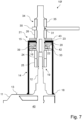
- FIG.7 an adapter arrangement 10f according to a sixth embodiment is shown, which differs from the other embodiments according to the invention by a clamping means 39 which is arranged between the bearing means 19 and the first insulating means 20 for applying pressure to the first insulating means 20 in the direction of the cover 15.
- the clamping means 39 is clamped between a first washer 42 and a third washer 33.
- Fig.8 shows a component assembly 100 which comprises a gas container 11 as described above with an outer surface 13 and a projection-like power connection 12 which extends beyond the outer surface 13 of the gas container 11 for conducting the electrical current into the gas container 11.
- the component assembly 100 further comprises a Fig.7 illustrated adapter arrangement 10f, which is attached to the outer surface 13 and to the connecting component 17 by a container sealant 18 in the form of a weld seam.
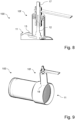
- Fig.9 is the Fig.8 shown component assembly 100 is shown in a perspective overall view.
- the gas container 11 is designed as a catalyst housing of an electrically heatable metal catalyst.
- the invention allows for further design principles. This means that the invention should not be considered limited to the embodiments explained with reference to the figures.
Landscapes
- Engineering & Computer Science (AREA)
- Chemical & Material Sciences (AREA)
- Chemical Kinetics & Catalysis (AREA)
- Combustion & Propulsion (AREA)
- Health & Medical Sciences (AREA)
- Toxicology (AREA)
- Mechanical Engineering (AREA)
- General Engineering & Computer Science (AREA)
- Ceramic Engineering (AREA)
- Architecture (AREA)
- Civil Engineering (AREA)
- Structural Engineering (AREA)
- Connector Housings Or Holding Contact Members (AREA)
- Filling Or Discharging Of Gas Storage Vessels (AREA)
- Casings For Electric Apparatus (AREA)
Description
- Die vorliegende Erfindung betrifft eine Adapteranordnung zum gasdichten Leiten von elektrischem Strom in einen Gasbehälter. Ferner betrifft die Erfindung einen Bauteilverbund mit einem Gasbehälter und einer Adapteranordnung zur Unterstützung eines stromdichten Leitens von elektrischem Strom in den Gasbehälter.
- Im Stand der Technik ist es bekannt, für den Startbetrieb eines Brennstoffzellensystems eine elektrische Heizvorrichtungen zu verwenden, um das Brennstoffzellensystem, insbesondere einen Brennstoffzellenstapel des Brennstoffzellensystems, möglichst schnell auf die gewünschte Betriebstemperatur zu bringen. Als Heizvorrichtungen sind elektrisch beheizbare Metallkatalysatoren bekannt. Diese weisen ein Katalysatorgehäuse auf, in welchem sich Katalysatormaterial befindet, das durch eine elektrisch betreibbare Hilfsvorrichtung schnell auf eine gewünschte Betriebstemperatur gebracht werden kann. Der Strom für die sich im Katalysatorgehäuse positionierte Hilfsvorrichtung wird durch einen über das Katalysatorgehäuse hinausragenden Stromanschluss in das Katalysatorgehäuse geleitet. In der Praxis hat sich nun gezeigt, dass die Dichtung am Stromanschluss zur Vermeidung eines Gasaustritts aus dem Katalysatorgehäuse während eines Funktionsbetriebs des Katalysators nicht den gewünschten Anforderungen entspricht. Genauer gesagt konnte bei unterschiedlichen Versuchen jeweils ein Gasaustritt im Bereich des Stromanschlusses festgestellt werden.
-
JP H07 208154 A JP H07 259543 A JP H09 032533 A DE 1 127 422 A undDE 196 27 840 A1 offenbaren jeweils eine Anordnung mit einer gasdichten elektrischen Durchführung durch einen Wandabschnitt. - Aufgabe der vorliegenden Erfindung ist es, der voranstehend beschriebenen Problematik zumindest teilweise Rechnung zu tragen. Insbesondere ist es Aufgabe der vorliegenden Erfindung, ein Hilfsmittel zum gasdichten Leiten von elektrischem Strom in einen Gasbehälter, insbesondere in Form eines wie einleitend beschriebenen Metallkatalysators, zu schaffen.
- Die voranstehende Aufgabe wird durch die Patentansprüche gelöst. Insbesondere wird die voranstehende Aufgabe durch die Adapteranordnung gemäß Anspruch 1, die Adapteranordnung gemäß Anspruch 7 sowie den Bauteilverbund gemäß Anspruch 15 gelöst. Weitere Vorteile der Erfindung ergeben sich aus den Unteransprüchen, der Beschreibung und den Zeichnungen. Dabei gelten Merkmale und Details, die im Zusammenhang mit den Adapteranordnungen beschrieben sind, selbstverständlich auch im Zusammenhang mit dem erfindungsgemäßen Bauteilverbund und jeweils umgekehrt, sodass bezüglich der Offenbarung zu den einzelnen Erfindungsaspekten stets wechselseitig Bezug genommen wird bzw. werden kann.
- Gemäß einem ersten Aspekt der vorliegenden Erfindung wird eine Adapteranordnung, zum gasdichten Leiten von elektrischem Strom in einen Gasbehälter, zur Verfügung gestellt, wobei der Gasbehälter einen vorsprungartigen Stromanschluss umfasst, der sich, zum Leiten des elektrischen Stroms in den Gasbehälter, von einem Innenvolumen des Gasbehälters über eine Außenfläche des Gasbehälters hinaus erstreckt. Die Adapteranordnung umfasst:
- ein Gehäuse zum wenigstens teilweisen Umschließen des Stromanschlusses in einer Umfangsrichtung des Stromanschlusses, wobei das Gehäuse einen Deckel mit einer Durchgangsöffnung für ein kontaktfreies Herausführen des Stromanschlusses aus dem Gehäuse aufweist,
- ein Behälter-Dichtmittel zum gasdichten Befestigen des Gehäuses am Gasbehälter,
- ein Lagermittel zum Befestigen am Stromanschluss innerhalb des Gehäuses,
- ein erstes Isoliermittel zum Positionieren zumindest teilweise zwischen dem Lagermittel und dem Deckel innerhalb des Gehäuses für eine elektrische Isolierung zwischen dem Lagermittel und dem Deckel,
- ein Gehäuse-Dichtmittel zum Befestigen an dem aus dem Gehäuse herausgeführten Stromanschluss zum Abdichten einer Lücke zwischen dem Stromanschluss und dem Deckel, und
- ein zweites Isoliermittel zum Positionieren zumindest teilweise zwischen dem Gehäuse-Dichtmittel und dem Deckel außerhalb des Gehäuses für eine elektrische Isolierung zwischen dem Gehäuse-Dichtmittel und dem Deckel.
- Mittels der erfindungsgemäßen Adapteranordnung ist es auf einfache und zuverlässige Weise möglich, gasdicht Strom in den Gasbehälter zu leiten. D.h., es kann verhindert werden, dass Gas aus dem Gasbehälter über die Adapteranordnung hinaus in die Umgebung des Gasbehälters austritt, während der Strom in den Gasbehälter geleitet wird. Unter dem Gasbehälter kann ein Katalysatorgehäuse eines elektrisch beheizbaren Katalysators, insbesondere eines Metallkatalysators wie beispielsweise eines Emicats, verstanden werden.
- Die erfindungsgemäße Adapteranordnung lässt sich mit einfachen Mitteln realisieren. Neben Standardbauteilen können zur Umsetzung der Adapteranordnung einfache geometrische Körper, beispielsweise ein einfacher Hohlzylinder für das Gehäuse, genutzt werden. Dadurch kann die Fertigung der Adapteranordnung schnell und kostengünstig realisiert werden. Ferner lässt sich die Adapteranordnung auf relativ kleinem Bauraum realisieren.
- Das Gehäuse kann einen Gehäusemantelabschnitt aufweisen, der ich zumindest abschnittsweise mantelförmig um den Stromanschluss herum erstreckt. Der Gehäusemantelabschnitt ist vorzugsweise zylinder- und/oder röhrenförmig ausgestaltet. Darunter, dass das Gehäuse den Stromanschluss wenigstens teilweise umschließt, kann verstanden werden, dass sich das Gehäuse und/oder der Gehäusemantelabschnitt nur um einen Teil des Stromanschlusses in Längsrichtung des Stromanschlusses herum erstreckt. Dass das Gehäuse zum wenigstens teilweisen Umschließen des Stromanschlusses in einer Umfangsrichtung des Stromanschlusses ausgestaltet ist kann verstanden werden, dass das Gehäuse den Stromanschluss in einer Längsrichtung des Stromanschlusses mantelförmig umgibt.
- Der Deckel ist, losgelöst von einem wie vorstehend beschriebenen Gehäusemantelabschnitt betrachtet, vorzugsweise scheibenförmig und/oder plattenförmig mit einer vorzugsweise zentral darin ausgestalteten Durchgangsöffnung konfiguriert. Besonders bevorzugt können der Gehäusemantelabschnitt und der Deckel als an wenigstens einer Stelle stoffschlüssig miteinander verbundene Bauteile bereitgestellt sein. Damit kann das Anbringen der Adapteranordnung am Gasbehälter vereinfacht werden.
- Unter dem kontaktfreien Herausführen des Stromanschlusses aus dem Gehäuse ist ein Herausführen des Stromanschlusses aus dem Gehäuse ohne direkten mechanischen Kontakt zwischen dem Stromanschluss und dem Gehäuse zu verstehen. Da der Stromanschluss sowie das Gehäuse vorzugsweise aus Metall und/oder einem elektrisch leitfähigen Material bestehen, können damit ein Kurzschluss und/oder eine andere elektrische Fehlfunktion verhindert werden.
- Ein Durchmesser und/oder eine Dimension der Durchgangsöffnung sind entsprechend größer als der Durchmesser und/oder die Dimension eines vorliegenden und/oder gewünschten Stromanschlusses im Bereich der Durchgangsöffnung gewählt.
- Unter dem Behälter-Dichtmittel kann ein Mittel zum stoffschlüssigen Verbinden des Gehäuses mit dem Gasbehälter verstanden werden. Das Behälter-Dichtmittel weist vorzugsweise eine Schweißnaht auf, durch welche das Gehäuse am Gasbehälter, insbesondere wenigstens an der Außenfläche des Gasbehälters, befestigt werden kann. Das Behälter-Dichtmittel wird vorzugsweise bereitgestellt, um den Bereich, in welchem das Gehäuse am Gasbehälter befestigt wird, gasdicht zu gestalten. D.h., das Behälter-Dichtmittel muss nicht den gesamten Behälter gegen einen Gasaustritt abdichten.
- Das Lagermittel dient zur Fixierung des ersten Isoliermittels in der gewünschten Position. Das Lagermittel kann mithin als Gegenlager zum Deckel, genauer gesagt zu einer Innenseite des Deckels, die in ein Innenvolumen des Gehäuses zeigt, verstanden werden. Das Lagermittel kann zur Positionierung des ersten Isoliermittels direkt am ersten Isoliermittel, bevorzugt mit direktem Flächenkontakt zwischen dem Lagermittel und dem ersten Isoliermittel, positioniert werden.
- Unter dem Abdichten der Lücke kann ein gasdichtes Verschließen wenigstens einer Lücke zwischen dem Stromanschluss und dem Deckel, die sich durch das kontaktfreie Herausführen des Stromanschlusses aus dem Gehäuse durch die Durchgangsöffnung ergibt, verstanden werden. D.h., das Gehäuse-Dichtmittel ist vorzugsweise zum Verhindern eines Gasaustritts aus dem Gehäuse konfiguriert. Das Verhindern des Gasaustritts kann direkt oder indirekt bewirkt werden. So kann das Gehäuse-Dichtmittel die Lücke direkt oder durch Hilfsmittel wie das zweite Isoliermittel gasdicht verschließen.
- Das erste Isoliermittel und das zweite Isoliermittel kann jeweils einen scheibenförmigen Isolierring aufweisen oder als scheibenförmiger Isolierring, zum ringförmigen Anordnen um den Stromanschluss, ausgestaltet sein. Das erste Isoliermittel und/oder das zweite Isoliermittel kann jeweils zum Abdichten des Behälters gegen einen Gasaustritt aus dem Gehäuse ausgestaltet sein.
- Das erste Isoliermittel und/oder das zweite Isoliermittel kann entsprechend aus elastischem Kunststoff bestehen oder einen entsprechenden elastischen Kunststoff aufweisen. Das erste Dichtmittel und/oder das zweite Dichtmittel ist bevorzugt jeweils einstückig ausgestaltet. Das Isoliermittel kann in einer bevorzugten Ausführungsform jedoch auch aus einem formstabilen, elektrisch nicht leitendem Material, beispielsweise aus Keramik, bestehen oder dieses Material für die elektrische Isolierfunktion zumindest entsprechend aufweisen.
- Gemäß einer weiteren Ausführungsform der vorliegenden Erfindung ist es möglich, dass bei einer Adapteranordnung der Stromanschluss einen ersten Stromanschluss-Gewindeabschnitt aufweist und das Lagermittel wenigstens eine Mutter zum Aufdrehen auf den ersten Gewindeabschnitt aufweist. Damit kann das Lagermittel besonders einfach und kostengünstig zur Verfügung gestellt werden. Bevorzugt weist das Lagermittel zwei Muttern auf, wobei eine Mutter als Kontermutter dient. Unter dem Aufdrehen kann ein Aufschrauben, ein Einschrauben oder ein Aufdrehen verstanden werden. Der Gewindeabschnitt kann mithin ein Außengewinde oder ein Innengewinde aufweisen. Der erste Stromanschluss-Gewindeabschnitt ist bevorzugt als Innengewinde an einer Innenumfangsfläche des Lagermittels und/oder der wenigstens einen Mutter ausgestaltet oder weist entsprechend ein Innengewinde auf, das auf ein korrespondierendes Außengewinde des Stromanschlusses aufgeschraubt werden kann.
- Ferner ist es möglich, dass bei einer Adapteranordnung gemäß der vorliegenden Erfindung der Stromanschluss einen zweiten Stromanschluss-Gewindeabschnitt aufweist und das Gehäuse-Dichtmittel wenigstens eine Mutter zum Aufdrehen auf den zweiten Gewindeabschnitt aufweist. D.h., die Mutter kann auf den zweiten Gewindeabschnitt aufgedreht werden. Auch damit lässt sich die Adapteranordnung relativ einfach und kostengünstig gestalten. Die wenigstens eine Mutter des Gehäuse-Dichtmittels kann beispielsweise auf das zweite Isoliermittel gedreht werden, bis sich ein gasdichter Verschluss zum Abdichten des Gehäuses ergibt. Das Gehäuse-Dichtmittel kann eine weitere Mutter aufweisen, die zur Fixierung der ersten Mutter des Gehäuse-Dichtmittels als Kontermutter auf den zweiten Stromanschluss-Gewindeabschnitt gedreht werden kann.
- Von weiterem Vorteil ist es, wenn eine erfindungsgemäße Adapteranordnung ein Spannmittel aufweist, das zur Druckbeaufschlagung des ersten Isoliermittels in Richtung des Deckels zumindest teilweise zwischen dem Lagermittel und dem ersten Isoliermittel angeordnet ist.
- Damit lässt sich eine einfache Positionierung des ersten Isoliermittels an einer gewünschten Position am Deckel, genauer gesagt an einer Innenseite des Deckels, erreichen. Das Spannmittel kann ein einstückiges Federelement aufweisen. Das Spannmittel ist zum Aufschieben auf den Stromanschluss bevorzugt ringförmig ausgestaltet. Eine erfindungsgemäße Adapteranordnung kann ferner wenigstens eine ringförmige Unterlegscheibe zur Positionierung zwischen dem Lagermittel und dem ersten Isoliermittel, zwischen dem Gehäuse-Dichtmittel und dem zweiten Isoliermittel und/oder zwischen dem Lagermittel und dem Spannmittel und/oder zwischen dem Spannmittel und dem ersten Isoliermittel aufweisen. Damit lassen sich die Kräfte auf die jeweiligen Bauteile auf kostengünstige und sichere Weise einfach, zuverlässig und effektiv übertragen. Unter einer Ringform ist vorliegend bevorzugt eine Form zu verstehen, die durch zwei konzentrisch zueinander angeordnete, im Querschnitt kreisförmige Mantelabschnitte gebildet wird. Gleichwohl können eine Außenumfangsfläche und/oder eine Innenumfangsfläche einer erfindungsgemäßen Ringform auch elliptisch und/oder eckig, beispielsweise sechseckig wie eine Mutter, ausgestaltet sein. Die Isoliermittel sind jeweils bevorzugt scheibenförmig, also mit einer ebenen oder im Wesentlichen ebenen Oberseite und einer ebenen Unterseite, ausgestaltet.
- Gemäß einer weiteren Ausgestaltungsvariante der vorliegenden Erfindung ist es möglich, dass eine Adapteranordnung ein elastisch verformbares erstes Stromleitmittel mit einem Stromleitmittel-Befestigungsabschnitt zum Befestigen des ersten Stromleitmittels außerhalb des Gehäuses am Stromanschluss zum Abgreifen von Strom vom Stromanschluss über das erste Stromleitmittel aufweist. Durch das erste Stromleitmittel können auf einfache und kostengünstige Weise thermisch bedingte Größenunterschiede des Gasbehälters, des Stromanschlusses und/oder des Gehäuses ausgeglichen werden. Der Stromleitmittel-Befestigungsabschnitt weist vorzugweise einen Stromleitmittel-Gewindeabschnitt, insbesondere ein Innengewinde im und/oder am Stromleitmittel, zum Aufdrehen des Stromleitmittels auf den Stromanschluss, auf.
- Das erste Stromleitmittel ist vorzugsweise plattenförmig oder im Wesentlichen plattenförmig ausgestaltet. D.h., eine Länge und eine Breite des Stromleitmittels sind jeweils um ein vielfaches länger und/oder höher als eine Höhe des Stromleitmittels. Außerdem weist das Stromleitmittel bevorzugt eine ebene oder im Wesentlichen ebene Oberseite und eine ebene oder im Wesentlichen ebene Unterseite auf.
- Das Stromleitmittel kann, insbesondere mit Bezug auf die Außenkontur des Stromleitmittels, quaderförmig oder im Wesentlichen quaderförmig ausgestaltet sein.
- Darüber hinaus kann eine Adapteranordnung gemäß der vorliegenden Erfindung ein Fixiermittel, zum zerstörungsfrei lösbaren Fixieren des ersten Stromleitmittels am Stromanschluss zumindest teilweise zwischen dem Fixiermittel und dem Gehäuse-Dichtmittel, aufweisen. Durch das Fixiermittel können der Zusammenbau sowie ein Auseinanderbauen im Wartungs- und/oder Reparaturfall besonders einfach durchgeführt werden. Bei einer Adapteranordnung gemäß der vorliegenden Erfindung kann es von Vorteil sein, wenn der Stromanschluss einen zweiten Stromanschluss-Gewindeabschnitt aufweist und das Fixiermittel wenigstens eine Mutter zum Aufdrehen auf den zweiten Stromanschluss-Gewindeabschnitt aufweist.
- Gemäß einem weiteren Aspekt der vorliegenden Erfindung wird eine Adapteranordnung zum gasdichten Leiten von elektrischem Strom in einen Gasbehälter zur Verfügung gestellt, wobei der Gasbehälter einen vorsprungartigen Stromanschluss umfasst, der sich, zum Leiten des elektrischen Stroms in den Gasbehälter, von einem Innenvolumen des Gasbehälters über eine Außenfläche des Gasbehälters hinaus erstreckt. Diese Adapteranordnung umfasst:
- ein Gehäuse zum wenigstens teilweisen Umschließen des Stromanschlusses in einer Umfangsrichtung des Stromanschlusses, wobei das Gehäuse einen Deckel mit einer Durchgangsöffnung aufweist,
- ein Verbindungsbauteil mit einem Verbindungsbauteil-Befestigungsabschnitt zum Befestigen des Verbindungsbauteils am Stromanschluss für einen elektrischen Kontakt zwischen dem Stromanschluss und dem Verbindungsbauteil und zum Leiten des elektrischen Stroms über das Verbindungsteil durch den Stromanschluss in den Gasbehälter, wobei die Durchgangsöffnung für ein kontaktloses Herausführen des am Stromanschluss befestigten Verbindungsbauteils aus dem Gehäuse ausgestaltet ist,
- ein Behälter-Dichtmittel zum gasdichten Befestigen des Gehäuses am Gasbehälter,
- ein Lagermittel, das innerhalb des Gehäuses am Verbindungsbauteil befestigt ist
- ein erstes Isoliermittel, das zumindest teilweise zwischen dem Lagermittel und dem Deckel innerhalb des Gehäuses für eine elektrische Isolierung zwischen dem Lagermittel und dem Deckel positioniert ist,
- ein Gehäuse-Dichtmittel, das an einem aus dem Gehäuse herausgeführten Abschnitt des Verbindungsbauteils zum Abdichten einer Lücke zwischen dem Verbindungsbauteil und dem Deckel befestigt ist, und
- ein zweites Isoliermittel, das zumindest teilweise zwischen dem Gehäuse-Dichtmittel und dem Deckel außerhalb des Gehäuses für eine elektrische Isolierung zwischen dem Gehäuse-Dichtmittel und dem Deckel positioniert ist.
- Die Adapteranordnung gemäß diesem Aspekt entspricht im Wesentlichen der Ausführungsform gemäß dem ersten Aspekt, wobei das Gehäuse nicht um den Stromanschluss, sondern um das Verbindungsbauteil herum abgedichtet wird. Dies hat den Vorteil, dass die Adapteranordnung noch einfacher und/oder flexibler an unterschiedlichen Gasbehältern und/oder Stromanschlüssen verwendet und/oder montiert werden kann. Die vorstehend mit Bezug auf die Adapteranordnung am Stromanschluss im Bereich des Gehäuses und insbesondere im Bereich der Durchgangsöffnung beschriebenen Merkmale treffen auf analoge Weise auf die Adapteranordnung gemäß dem zweiten Aspekt und mit Bezug auf das Verbindungsbauteil zu.
- So ist es bei einer Adapteranordnung gemäß dem zweiten Aspekt beispielsweise möglich, dass das Verbindungsbauteil einen ersten Verbindungsbauteil-Gewindeabschnitt aufweist und das Lagermittel wenigstens eine Mutter zum Aufdrehen auf den ersten Gewindeabschnitt aufweist. Ferner ist es möglich, dass das Verbindungsbauteil einen zweiten Verbindungsbauteil-Gewindeabschnitt aufweist und das Gehäuse-Dichtmittel wenigstens eine Mutter zum Aufdrehen auf den zweiten Verbindungsbauteil-Gewindeabschnitt aufweist.
- Die Adapteranordnung mit Verbindungsbauteil weist ebenso ein Spannmittel auf, das zur Druckbeaufschlagung des ersten Isoliermittels in Richtung des Deckels zumindest teilweise zwischen dem Lagermittel und dem ersten Isoliermittel angeordnet ist.
- Das elastisch verformbare erste Stromleitmittel kann den Stromleitmittel-Befestigungsabschnitt zum Befestigen des ersten Stromleitmittels außerhalb des Gehäuses am Verbindungsbauteil zum Abgreifen von Strom von dem Verbindungsbauteil über das erste Stromleitmittel aufweisen. Das Fixiermittel kann zum zerstörungsfrei lösbaren Fixieren des ersten Stromleitmittels am Verbindungsbauteil zumindest teilweise zwischen dem Fixiermittel und dem Gehäuse-Dichtmittel konfiguriert sein.
- Darüber hinaus ist es bei einer Adapteranordnung gemäß dem zweiten Aspekt möglich, dass das Verbindungsbauteil einen zweiten Verbindungsbauteil-Gewindeabschnitt aufweist und das Fixiermittel wenigstens eine Mutter zum Aufdrehen auf den zweiten Verbindungsbauteil-Gewindeabschnitt aufweist. Der Verbindungsbauteil-Befestigungsabschnitt kann einen dritten Verbindungsbauteil-Gewindeabschnitt zum Aufdrehen des Verbindungsbauteils auf einen korrespondierenden Stromanschluss-Gewindeabschnitt des Stromanschlusses aufweisen. Damit lässt sich das Verbindungsbauteil schnell, einfach und zuverlässig mit dem Stromanschluss verbinden. Der dritte Verbindungsbauteil-Gewindeabschnitt weist vorzugsweise ein Innengewinde auf, das auf ein korrespondierendes Außengewinde des Stromanschlusses geschraubt werden kann.
- Gemäß einer weiteren Ausgestaltungsvariante der vorliegenden Erfindung ist es möglich, dass das Verbindungsbauteil bei einer Adapteranordnung gemäß dem zweiten Aspekt einstückig, insbesondere stift- und/oder zapfenförmig, ausgestaltet ist. Die Adapteranordnung kann damit besonders stabil, platzsparend und kostengünstig zur Verfügung gestellt werden.
- Von weiterem Vorteil kann es sein, wenn das Verbindungsbauteil bei einer Adapteranordnung gemäß der vorliegenden Erfindung einen vierten Verbindungsbauteil-Gewindeabschnitt an einer Stirnseite des Verbindungsbauteils, für eine Schraubverbindung zwischen einem weiteren Stromanschluss und dem Verbindungsbauteil, aufweist.
- Damit lässt sich auf platzsparende und einfache Weise ein Stromanschlussabschnitt zum Anbinden eines weiteren Stromanschlusses an das Verbindungsbauteil außerhalb des Gehäuses realisieren.
- Ferner kann eine Adapteranordnung gemäß der vorliegenden Erfindung ein elastisch verformbares zweites Stromleitmittel aufweisen, wobei der Stromanschluss und das Verbindungsbauteil für eine elektrische Verbindung zwischen dem Stromanschluss und dem Verbindungsbauteil durch das zweite Stromleitmittel mechanisch miteinander verbunden sind. Durch das zweite Stromleitmittel können auf einfache und kostengünstige Weise thermisch bedingte Größenunterschiede des Gasbehälters, des Stromanschlusses, des Verbindungsbauteils und/oder des Gehäuses ausgeglichen werden. Das zweite Stromleitmittel weist vorzugweise einen ersten Stromleitmittel-Gewindeabschnitt und/oder einen zweiten Stromleitmittel-Gewindeabschnitt auf, die jeweils insbesondere ein Innengewinde im und/oder am zweiten Stromleitmittel aufweisen. Durch die Gewindeabschnitte kann das zweite Stromleitmittel einfach mit dem Stromanschluss und/oder dem Verbindungsbauteil zum Herstellen der gewünschten elektrischen Verbindung zwischen dem Stromanschluss, dem zweiten Stromleitmittel und dem Verbindungsbauteil, verbunden werden.
- Das zweite Stromleitmittel ist bevorzugt plattenförmig oder im Wesentlichen plattenförmig ausgestaltet. Außerdem weist das zweite Stromleitmittel bevorzugt eine ebene oder im Wesentlichen ebene Oberseite und eine ebene oder im Wesentlichen ebene Unterseite auf. Das Stromleitmittel kann, insbesondere mit Bezug auf die Außenkontur des Stromleitmittels, quaderförmig oder im Wesentlichen quaderförmig ausgestaltet sein.
- Gemäß einem weiteren Aspekt der vorliegenden Erfindung wird ein Bauteilverbund zur Verfügung gestellt. Der Bauteilverbund weist einen Gasbehälter mit einer Außenfläche und einem vorsprungartigen Stromanschluss auf, wobei sich der Stromanschluss, zum Leiten eines elektrischen Stroms in den Gasbehälter, von einem Innenvolumen des Gasbehälters über die Außenfläche des Gasbehälters hinaus erstreckt. Ferner weist der Bauteilverbund eine an der Außenfläche sowie am Stromanschluss befestigte und wie vorstehend im Detail beschriebene Adapteranordnung auf.
- Damit bringt ein erfindungsgemäßer Bauteilverbund die gleichen Vorteile mit sich, wie sie ausführlich mit Bezug auf die erfindungsgemäße Adapteranordnung beschrieben worden sind. Der Stromanschluss ist bevorzugt stift- und/oder zapfenförmig ausgestaltet.
- Weitere, die Erfindung verbessernde Maßnahmen ergeben sich aus der nachfolgenden Beschreibung zu verschiedenen Ausführungsbeispielen der Erfindung, welche in den Figuren schematisch dargestellt sind.
- Es zeigen jeweils schematisch:
- Figur 1
- eine Adapteranordnung gemäß einer ersten Ausführungsform der vorliegenden Erfindung,
- Figur 2
- eine Adapteranordnung gemäß einer zweiten Ausführungsform der vorliegenden Erfindung,
- Figur 3
- ein erfindungsgemäßes Verbindungsbauteil,
- Figur 4
- eine Adapteranordnung gemäß einer dritten Ausführungsform der vorliegenden Erfindung,
- Figur 5
- eine Adapteranordnung gemäß einer vierten Ausführungsform der vorliegenden Erfindung,
- Figur 6
- eine Adapteranordnung gemäß einer fünften Ausführungsform der vorliegenden Erfindung,
- Figur 7
- eine Adapteranordnung gemäß einer sechsten Ausführungsform der vorliegenden Erfindung,
- Figur 8
- einen Bauteilverbund gemäß einer bevorzugten Ausführungsform der vorliegenden Erfindung in einer Schnittdarstellung, und
- Figur 9
- eine perspektivische Gesamtansicht des in
Fig. 8 dargestellten Bauteilverbunds. - Elemente mit gleicher Funktion und Wirkungsweise sind in den Figuren jeweils mit den gleichen Bezugszeichen versehen.
-
Fig. 1 zeigt eine Adapteranordnung 10a zum gasdichten Leiten von elektrischem Strom in einen Gasbehälter 11 gemäß einer ersten Ausführungsform. Der Gasbehälter 11 weist einen stiftförmigen, vorsprungartigen Stromanschluss 12 auf, der sich, zum Leiten des elektrischen Stroms in den Gasbehälter 11, von einem Innenvolumen 40 des Gasbehälters 11 über eine Außenfläche 13 des Gasbehälters 11 hinaus erstreckt. Die Adapteranordnung 10a weist ein Gehäuse 14 zum Umschließen des Stromanschlusses 12 in einer Umfangsrichtung des Stromanschlusses 12 in dem Bereich, in welchem der Stromanschluss 12 aus dem Gasbehälter 11 ragt, auf. Das Gehäuse 14 weist einen Deckel 15 mit einer Durchgangsöffnung 16 für ein kontaktfreies Herausführen des Stromanschlusses 12 aus dem Gehäuse 14 auf. Die Adapteranordnung 10a weist ferner ein Behälter-Dichtmittel 18 in Form einer Schweißnaht zum gasdichten Befestigen des Gehäuses 14 am Gasbehälter 11 auf. D.h., das Gehäuse 14 ist durch die Schweißnaht des Behälter-Dichtmittels 18 am Gasbehälter 11 stoffschlüssig angebunden. Außerdem weist die Adapteranordnung 10a ein innerhalb des Gehäuses 14 am Stromanschluss 12 befestigtes Lagermittel 19 auf. Das inFig. 1 dargestellte Lagermittel 19 weist eine erste Mutter 24 und eine Kontermutter 25 auf, die jeweils auf einen korrespondierenden Gewindeabschnitt des Stromanschlusses 12 gedreht sind. Ferner weist die gezeigte Adapteranordnung 10a ein erstes Isoliermittel 20 auf, das zwischen dem Lagermittel 19 und dem Deckel 15 innerhalb des Gehäuses 14 für eine elektrische Isolierung zwischen dem Lagermittel 19 und dem Deckel 15 positioniert ist. Die Adapteranordnung 10a weist zudem ein Gehäuse-Dichtmittel 21 auf, das an dem aus dem Gehäuse 14 herausgeführten Stromanschluss 12 befestigt ist, um eine Lücke 22 zwischen dem Stromanschluss 12 und dem Deckel 15 gegen Gasaustritt aus dem Innenvolumen 40 abzudichten. Darüber hinaus weist die gezeigte Adapteranordnung 10a ein zweites Isoliermittel 23 auf, das zwischen dem Gehäuse-Dichtmittel 21 und dem Deckel 15 außerhalb des Gehäuses 14 für eine elektrische Isolierung zwischen dem Gehäuse-Dichtmittel 21 und dem Deckel 15 positioniert ist. - Das erste Isoliermittel 20 und das zweite Isoliermittel 23 sind jeweils ringscheibenförmig ausgestaltet. Das Gehäuse-Dichtmittel 21 weist wenigstens eine Mutter 26 auf, die auf einen zweiten Stromanschluss-Gewindeabschnitt des Stromanschlusses 12 gedreht und dort befestigt ist.
- Die in
Fig. 1 dargestellte Adapteranordnung 10a weist ferner ein elastisch verformbares erstes Stromleitmittel 30 mit einem inFig. 7 dargestellten Stromleitmittel-Befestigungsabschnitt 31 auf, durch welchen das erste Stromleitmittel 30 außerhalb des Gehäuses 14 am Stromanschluss 12 befestigt ist, sodass Strom vom Stromanschluss 17 über das erste Stromleitmittel 30 geleitet werden kann. Der Stromleitmittel-Befestigungsabschnitt 31 ist im gezeigten Beispiel in Form eines Gewindeabschnitts ausgestaltet, durch welchen das erste Stromleitmittel 30 an einem korrespondierenden Gewinde des Stromanschlusses 12 befestigt ist. - Die gezeigte Adapteranordnung 10a weist zudem ein Fixiermittel 34 in Form einer ersten Mutter 35 und einer zweiten Mutter 36 in Form einer zum zerstörungsfrei lösbaren Fixieren des ersten Stromleitmittels 30 am Stromanschluss 12 zwischen dem Fixiermittel 34 und dem Gehäuse-Dichtmittel 21 auf. Das dargestellte Stromleitmittel 30 ist demnach zwischen der Mutter 26 des Gehäuse-Dichtmittels 21 und der Mutter 35 des Fixiermittels 34 eingespannt.
- Bei dem gezeigten Beispiel sind zwischen dem ersten Isoliermittel 20 und dem Deckel 15 eine erste Unterlegscheibe 42 und zwischen dem zweiten Isoliermittel 23 und der Mutter 26 eine zweite Unterlegscheibe 43 angeordnet. In einem Bereich, in welchem der Stromanschluss 12 aus dem Gasbehälter 11 geführt wird, ist ein drittes Isoliermittel 41 angeordnet, durch welches der Stromanschluss 12 vom Gasbehälter 11 elektrisch isoliert ist.
- In
Fig. 2 ist eine Adapteranordnung 10b gemäß einer zweiten Ausführungsform dargestellt. Die inFig. 2 gezeigte Adapteranordnung 10b unterscheidet sich von der inFig. 1 gezeigten Adapteranordnung 10a insbesondere durch ein einstückiges Verbindungsbauteil 17. Das dargestellte Verbindungsbauteil 17 weist einen inFig. 3 dargestellten Verbindungsbauteil-Befestigungsabschnitt 27a zum Befestigen des Verbindungsbauteils 17 am Stromanschluss 12 auf, um einen elektrischen Kontakt zwischen dem Stromanschluss 12 und dem Verbindungsbauteil 17 herzustellen und um den elektrischen Strom über das Verbindungsteil 17 durch den Stromanschluss 12 in den Gasbehälter 11 zu leiten. Die Durchgangsöffnung 16 ist entsprechend für ein kontaktloses Herausführen des am Stromanschluss 12 befestigten Verbindungsbauteils 17 aus dem Gehäuse 14 ausgestaltet. - Das Gehäuse-Dichtmittel 21 ist an einem aus dem Gehäuse 14 herausgeführten Abschnitt des Verbindungsbauteils 17 befestigt, um eine Lücke 22 zwischen dem Verbindungsbauteil 17 und dem Deckel 15 abzudichten.
- Das Verbindungsbauteil 17 weist einen in
Fig. 3 dargestellten ersten Verbindungsbauteil-Gewindeabschnitt 28 auf, an welchem das Lagermittel 19 in Form der beiden Muttern 24, 25 befestigt ist. Das Verbindungsbauteil 17 weist einen ebenfalls inFig. 3 dargestellten zweiten Verbindungsbauteil-Gewindeabschnitt 29 auf, an welchem das Gehäuse-Dichtmittel 21 in Form der Mutter 26 befestigt ist. Am zweiten Verbindungsbauteil-Gewindeabschnitt 29 ist ferner das Fixiermittel 34 in Form der beiden Muttern 35, 36 befestigt. - In
Fig. 3 ist ein zapfenförmiges Verbindungsbauteil 17 dargestellt, an welchem der Verbindungsbauteil-Befestigungsabschnitt 27a, ein zugehöriger dritter Verbindungsbauteil-Gewindeabschnitt 37, ein erster Verbindungsbauteil-Gewindeabschnitt 28, ein zweiter Verbindungsbauteil-Gewindeabschnitt 29 sowie ein vierter Verbindungsbauteil-Gewindeabschnitt 38 ausgestaltet sind. Der Verbindungsbauteil-Gewindeabschnitt 37 ist zum Aufdrehen des Verbindungsbauteils 17 auf einen korrespondierenden Stromanschluss-Gewindeabschnitt des Stromanschlusses 12 ausgestaltet. Der vierte Verbindungsbauteil-Gewindeabschnitt 38 ist an einer Stirnseite des Verbindungsbauteils 17 für eine Schraubverbindung zwischen einem inFig. 6 dargestellten weiteren Stromanschluss 12' und dem Verbindungsbauteil 17 ausgestaltet. -
Fig. 4 zeigt eine Adapteranordnung 10c gemäß einer dritten Ausführungsform. In dieser Ausführungsform ist ein weiterer Stromanschluss 12' dargestellt, der am ersten Stromleitmittel befestigbar ist. - In
Fig. 5 ist eine Adapteranordnung 10d gemäß einer vierten Ausführungsform dargestellt. Diese Ausführungsform ist durch ein elastisch verformbares zweites Stromleitmittel 32 gekennzeichnet, wobei der Stromanschluss 12 und das Verbindungsbauteil 17 für eine elektrische Verbindung zwischen dem Stromanschluss 12 und dem Verbindungsbauteil 17 durch das zweite Stromleitmittel 32 mechanisch miteinander verbunden sind. - Das zweite Stromleitmittel 32 ist in der dargestellten Ausführungsform plattenförmig oder im Wesentlichen plattenförmig ausgestaltet und sowohl am Verbindungsbauteil 17, genauer gesagt an einem Verbindungsbauteil-Befestigungsabschnitt 27b des Verbindungsbauteils 17, als auch am Stromanschluss 12 jeweils durch zwei Muttern gesichert.
-
Fig. 6 zeigt eine Adapteranordnung 10e gemäß einer fünften Ausführungsform, bei welcher im vierten Verbindungsbauteil-Gewindeabschnitt 38 an der Stirnseite des Verbindungsbauteils 17 ein weiterer Stromanschluss 12' eingeschraubt ist. - In
Fig. 7 ist eine Adapteranordnung 10f gemäß einer sechsten Ausführungsform dargestellt, die sich von den anderen Ausführungsformen erfindungsgemäss durch ein Spannmittel 39 unterscheidet, das zur Druckbeaufschlagung des ersten Isoliermittels 20 in Richtung des Deckels 15 zwischen dem Lagermittel 19 und dem ersten Isoliermittel 20 angeordnet ist. Das Spannmittel 39 ist zwischen einer ersten Unterlegscheibe 42 und einer dritten Unterlegscheibe 33 eingespannt. -
Fig. 8 zeigt einen Bauteilverbund 100, der einen wie vorstehend beschriebenen Gasbehälter 11 mit einer Außenfläche 13 und einem vorsprungartigen Stromanschluss 12 umfasst, der sich, zum Leiten des elektrischen Stroms in den Gasbehälter 11, über die Außenfläche 13 des Gasbehälters 11 hinaus erstreckt. Der Bauteilverbund 100 umfasst ferner eine wie inFig. 7 dargestellte Adapteranordnung 10f, die durch ein Behälter-Dichtmittel 18 in Form einer Schweißnaht an der Außenfläche 13 sowie am Verbindungsbauteil 17 befestigt ist. InFig. 9 ist der inFig. 8 dargestellte Bauteilverbund 100 in einer perspektivischen Gesamtansicht dargestellt. Der Gasbehälter 11 ist in der gezeigten Ausführungsform als Katalysatorgehäuse eines elektrisch beheizbaren Metallkatalysators ausgestaltet. Die Erfindung lässt neben den dargestellten Ausführungsformen weitere Gestaltungsgrundsätze zu. D. h. die Erfindung soll nicht auf die mit Bezug auf die Figuren erläuterten Ausführungsbeispiele beschränkt betrachtet werden. -
- 10a - 10f
- Adapteranordnung
- 11
- Gasbehälter
- 12
- Stromanschluss
- 13
- Außenfläche
- 14
- Gehäuse
- 15
- Deckel
- 16
- Durchgangsöffnung
- 17
- Verbindungsbauteil
- 18
- Behälter-Dichtmittel
- 19
- Lagermittel
- 20
- erstes Isoliermittel
- 21
- Gehäuse-Dichtmittel
- 22
- Lücke
- 23
- zweites Isoliermittel
- 24
- Mutter
- 25
- Mutter
- 26
- Mutter
- 27a
- Verbindungsbauteil-Befestigungsabschnitt
- 27b
- Verbindungsbauteil-Befestigungsabschnitt
- 28
- erster Verbindungsbauteil-Gewindeabschnitt
- 29
- zweiter Verbindungsbauteil-Gewindeabschnitt
- 30
- erstes Stromleitmittel
- 31
- Stromleitmittel-Befestigungsabschnitt
- 32
- zweites Stromleitmittel
- 33
- dritte Unterlegscheibe
- 34
- Fixiermittel
- 35
- Mutter
- 36
- Mutter
- 37
- dritter Verbindungsbauteil-Gewindeabschnitt
- 38
- vierter Verbindungsbauteil-Gewindeabschnitt
- 39
- Spannmittel
- 40
- Innenvolumen
- 41
- drittes Isoliermittel
- 42
- erste Unterlegscheibe
- 43
- zweite Unterlegscheibe
- 100
- Bauteilverbund
Claims (15)
- Adapteranordnung (10a; 10b; 10c; 10d; 10e; 10f) zum gasdichten Leiten von elektrischem Strom in einen Gasbehälter (11), wobei der Gasbehälter (11) einen vorsprungartigen Stromanschluss (12) umfasst, der sich, zum Leiten des elektrischen Stroms in den Gasbehälter (11), von einem Innenvolumen (40) des Gasbehälters (11) über eine Außenfläche (13) des Gasbehälters (11) hinaus erstreckt, aufweisend:- ein Gehäuse (14) zum wenigstens teilweisen Umschließen des Stromanschlusses (12) in einer Umfangsrichtung des Stromanschlusses (12), wobei das Gehäuse (14) einen Deckel (15) mit einer Durchgangsöffnung (16) für ein kontaktfreies Herausführen des Stromanschlusses (12) aus dem Gehäuse (14) aufweist,- ein Behälter-Dichtmittel (18) zum gasdichten Befestigen des Gehäuses (14) am Gasbehälter (11),- ein Lagermittel (19) zum Befestigen am Stromanschluss (12) innerhalb des Gehäuses (14),- ein erstes Isoliermittel (20) zum Positionieren zumindest teilweise zwischen dem Lagermittel (19) und dem Deckel (15) innerhalb des Gehäuses (14) für eine elektrische Isolierung zwischen dem Lagermittel (19) und dem Deckel (15),- ein Gehäuse-Dichtmittel (21) zum Befestigen an dem aus dem Gehäuse (14) herausgeführten Stromanschluss (12) zum Abdichten einer Lücke (22) zwischen dem Stromanschluss (12) und dem Deckel (15), und- ein zweites Isoliermittel (23) zum Positionieren zumindest teilweise zwischen dem Gehäuse-Dichtmittel (21) und dem Deckel (15) außerhalb des Gehäuses (14) für eine elektrische Isolierung zwischen dem Gehäuse-Dichtmittel (21) und dem Deckel (15),gekennzeichnet durch
ein Spannmittel (39), das zur Druckbeaufschlagung des ersten Isoliermittels (20) in Richtung des Deckels (15) zumindest teilweise zwischen dem Lagermittel (19) und dem ersten Isoliermittel (20) angeordnet ist. - Adapteranordnung (10a; 10b; 10c; 10d; 10e; 10f) nach Anspruch 1, wobei der Stromanschluss (12) einen ersten Stromanschluss-Gewindeabschnitt aufweist und das Lagermittel (19) wenigstens eine Mutter (24, 25) zum Aufdrehen auf den ersten Stromanschluss-Gewindeabschnitt aufweist.
- Adapteranordnung (10a; 10b; 10c; 10d; 10e; 10f) nach einem der voranstehenden Ansprüche,
wobei der Stromanschluss (12) einen zweiten Stromanschluss-Gewindeabschnitt aufweist und das Gehäuse-Dichtmittel (21) wenigstens eine Mutter (26) zum Aufdrehen auf den zweiten Stromanschluss-Gewindeabschnitt aufweist. - Adapteranordnung (10a; 10b; 10c; 10d; 10e; 10f) nach einem der voranstehenden Ansprüche,
aufweisend ein elastisch verformbares erstes Stromleitmittel (30) mit einem Stromleitmittel-Befestigungsabschnitt (31) zum Befestigen des ersten Stromleitmittels (30) außerhalb des Gehäuses (14) am Stromanschluss (12) zum Abgreifen von Strom vom Stromanschluss (17) über das erste Stromleitmittel (30). - Adapteranordnung (10a; 10b; 10c; 10d; 10e; 10f) nach Anspruch 4, aufweisend ein Fixiermittel (34) zum zerstörungsfrei lösbaren Fixieren des ersten Stromleitmittels (30) am Stromanschluss (12) zumindest teilweise zwischen dem Fixiermittel (34) und dem Gehäuse-Dichtmittel (21).
- Adapteranordnung (10a; 10b; 10c; 10d; 10e; 10f) nach Anspruch 5, wobei der Stromanschluss (12) einen zweiten Stromanschluss-Gewindeabschnitt aufweist und das Fixiermittel (34) wenigstens eine Mutter (35, 36) zum Aufdrehen auf den zweiten Stromanschluss-Gewindeabschnitt aufweist.
- Adapteranordnung (10b; 10c; 10d; 10e; 10f) zum gasdichten Leiten von elektrischem Strom in einen Gasbehälter (11), wobei der Gasbehälter (11) einen vorsprungartigen Stromanschluss (12) umfasst, der sich, zum Leiten des elektrischen Stroms in den Gasbehälter (11), von einem Innenvolumen (40) des Gasbehälters (11) über eine Außenfläche (13) des Gasbehälters (11) hinaus erstreckt, aufweisend:- ein Gehäuse (14) zum wenigstens teilweisen Umschließen des Stromanschlusses (12) in einer Umfangsrichtung des Stromanschlusses (12), wobei das Gehäuse (14) einen Deckel (15) mit einer Durchgangsöffnung (16) aufweist,- ein Verbindungsbauteil (17) mit einem Verbindungsbauteil-Befestigungsabschnitt (27a; 27b) zum Befestigen des Verbindungsbauteils (17) am Stromanschluss (12) für einen elektrischen Kontakt zwischen dem Stromanschluss (12) und dem Verbindungsbauteil (17) und zum Leiten des elektrischen Stroms über das Verbindungsteil (17) durch den Stromanschluss (12) in den Gasbehälter (11), wobei die Durchgangsöffnung (16) für ein kontaktloses Herausführen des am Stromanschluss (12) befestigten Verbindungsbauteils (17) aus dem Gehäuse (14) ausgestaltet ist,- ein Behälter-Dichtmittel (18) zum gasdichten Befestigen des Gehäuses (14) am Gasbehälter (11),- ein Lagermittel (19), das innerhalb des Gehäuses (14) am Verbindungsbauteil (17) befestigt ist- ein erstes Isoliermittel (20), das zumindest teilweise zwischen dem Lagermittel (19) und dem Deckel (15) innerhalb des Gehäuses (14) für eine elektrische Isolierung zwischen dem Lagermittel (19) und dem Deckel (15) positioniert ist,- ein Gehäuse-Dichtmittel (21), das an einem aus dem Gehäuse (14) herausgeführten Abschnitt des Verbindungsbauteils (17) zum Abdichten einer Lücke (22) zwischen dem Verbindungsbauteil (17) und dem Deckel (15) befestigt ist, und- ein zweites Isoliermittel (23), das zumindest teilweise zwischen dem Gehäuse-Dichtmittel (21) und dem Deckel (15) außerhalb des Gehäuses (14) für eine elektrische Isolierung zwischen dem Gehäuse-Dichtmittel (21) und dem Deckel (15) positioniert ist,gekennzeichnet durch
ein Spannmittel (39), das zur Druckbeaufschlagung des ersten Isoliermittels (20) in Richtung des Deckels (15) zumindest teilweise zwischen dem Lagermittel (19) und dem ersten Isoliermittel (20) angeordnet ist. - Adapteranordnung (10b; 10c; 10d; 10e; 10f) nach Anspruch 7,
wobei das Verbindungsbauteil (17) einen ersten Verbindungsbauteil-Gewindeabschnitt (28) aufweist und das Lagermittel (19) wenigstens eine Mutter (24, 25) zum Aufdrehen auf den ersten Gewindeabschnitt (28) aufweist. - Adapteranordnung (10b; 10c; 10d; 10e; 10f) nach einem der Ansprüche 7 bis 8, wobei das Verbindungsbauteil (17) einen zweiten Verbindungsbauteil-Gewindeabschnitt (29) aufweist und das Gehäuse-Dichtmittel (21) wenigstens eine Mutter (26) zum Aufdrehen auf den zweiten Verbindungsbauteil-Gewindeabschnitt (29) aufweist.
- Adapteranordnung (10b; 10c; 10d; 10f) nach einem der Ansprüche 7 bis 9, aufweisend ein elastisch verformbares erstes Stromleitmittel (30) mit einem Stromleitmittel-Befestigungsabschnitt (31) zum Befestigen des ersten Stromleitmittels (30) außerhalb des Gehäuses (14) am Verbindungsbauteil (17) zum Abgreifen von Strom von dem Verbindungsbauteil (17) über das erste Stromleitmittel (30).
- Adapteranordnung (10b; 10c; 10d; 10f) nach Anspruch 10,
aufweisend ein Fixiermittel (34) zum zerstörungsfrei lösbaren Fixieren des ersten Stromleitmittels (30) am Verbindungsbauteil (17) zumindest teilweise zwischen dem Fixiermittel (34) und dem Gehäuse-Dichtmittel (21). - Adapteranordnung (10b; 10c; 10e; 10f) nach einem der Ansprüche 7 bis 11, wobei der Verbindungsbauteil-Befestigungsabschnitt (27a) einen dritten Verbindungsbauteil-Gewindeabschnitt (37) zum Aufdrehen des Verbindungsbauteils (17) auf einen korrespondierenden Stromanschluss-Gewindeabschnitt des Stromanschlusses (12) aufweist.
- Adapteranordnung (10b; 10c; 10d; 10e; 10f) nach einem der Ansprüche 7 bis 12,
wobei das Verbindungsbauteil (17) einstückig ausgestaltet ist. - Adapteranordnung (10d) nach einem der Ansprüche 7 bis 13,
aufweisend ein elastisch verformbares zweites Stromleitmittel (32), wobei der Stromanschluss (12) und das Verbindungsbauteil (17) für eine elektrische Verbindung zwischen dem Stromanschluss (12) und dem Verbindungsbauteil (17) durch das zweite Stromleitmittel (32) mechanisch miteinander verbunden sind. - Bauteilverbund (100), aufweisend einen Gasbehälter (11) mit einer Außenfläche (13) und einem vorsprungartigen Stromanschluss (12), wobei sich der Stromanschluss (12), zum Leiten eines elektrischen Stroms in den Gasbehälter (11), von einem Innenvolumen (40) des Gasbehälters (11) über die Außenfläche (13) des Gasbehälters (11) hinaus erstreckt, und einer an der Außenfläche (13) sowie am Stromanschluss (12) befestigten Adapteranordnung (10d) nach einem der voranstehenden Ansprüche.
Applications Claiming Priority (2)
| Application Number | Priority Date | Filing Date | Title |
|---|---|---|---|
| ATA50292/2020A AT523645B1 (de) | 2020-04-06 | 2020-04-06 | Adapteranordnung und Bauteilverbund |
| PCT/AT2021/060111 WO2021203152A1 (de) | 2020-04-06 | 2021-04-01 | Adapteranordnung und bauteilverbund |
Publications (2)
| Publication Number | Publication Date |
|---|---|
| EP4133166A1 EP4133166A1 (de) | 2023-02-15 |
| EP4133166B1 true EP4133166B1 (de) | 2024-08-28 |
Family
ID=75438534
Family Applications (1)
| Application Number | Title | Priority Date | Filing Date |
|---|---|---|---|
| EP21717309.5A Active EP4133166B1 (de) | 2020-04-06 | 2021-04-01 | Adapteranordnung und bauteilverbund |
Country Status (6)
| Country | Link |
|---|---|
| EP (1) | EP4133166B1 (de) |
| JP (1) | JP7747653B2 (de) |
| CN (1) | CN115667682B (de) |
| AT (1) | AT523645B1 (de) |
| DE (1) | DE112021001036A5 (de) |
| WO (1) | WO2021203152A1 (de) |
Families Citing this family (1)
| Publication number | Priority date | Publication date | Assignee | Title |
|---|---|---|---|---|
| DE102022113905A1 (de) | 2022-06-02 | 2023-12-07 | Purem GmbH | Anschlusseinheit |
Family Cites Families (24)
| Publication number | Priority date | Publication date | Assignee | Title |
|---|---|---|---|---|
| DE913334C (de) * | 1943-03-09 | 1954-06-10 | Voigt & Haeffner Ag | Fluessigkeits- und gasdichter Verschluss fuer Rohrheizkoerper |
| DE921511C (de) * | 1949-01-20 | 1954-12-20 | Hayward Tyler & Co Ltd | Fluessigkeitsdichte Durchfuehrung fuer elektrische Leiter |
| DE1678790U (de) * | 1953-12-10 | 1954-06-24 | Hydrawerk Ag | Elektrische durchfuehrung. |
| DE1127422B (de) * | 1960-03-08 | 1962-04-12 | Siemens Ag | Gasdichte elektrische Mehrfachdurchfuehrung durch die Wand eines Hochdruckbehaelters |
| CH428881A (de) * | 1965-07-16 | 1967-01-31 | Balzers Patent Beteilig Ag | Elektrische Durchführung in der Wand einer Vakuumaufdampfanlage |
| US4015228A (en) * | 1974-06-10 | 1977-03-29 | Matsushita Electric Industrial Co., Ltd. | Surge absorber |
| AT377345B (de) * | 1983-04-07 | 1985-03-11 | Ver Edelstahlwerke Ag | Drehdurchfuehrung |
| DE3418156A1 (de) * | 1984-05-16 | 1985-11-28 | Standard Elektrik Lorenz Ag, 7000 Stuttgart | Elektrische durchfuehrung durch eine metallplatte |
| JPH06260305A (ja) * | 1993-03-08 | 1994-09-16 | Fuji Electric Co Ltd | 避雷器の電流端子引出し構造 |
| JP3179651B2 (ja) * | 1993-03-22 | 2001-06-25 | 日本碍子株式会社 | ヒーターユニット |
| JPH07208154A (ja) * | 1994-01-18 | 1995-08-08 | Nippondenso Co Ltd | 自己発熱型メタル担体 |
| JP3680320B2 (ja) * | 1994-06-17 | 2005-08-10 | 株式会社デンソー | 自己発熱型触媒コンバータ |
| JPH0932533A (ja) * | 1995-07-12 | 1997-02-04 | Nissan Motor Co Ltd | 内燃機関の排気浄化装置 |
| DE19533088A1 (de) * | 1995-09-07 | 1997-03-13 | Emitec Emissionstechnologie | Elektrische isolierende Durchführung mit einer Elektrokorrosionsschutzeinrichtung |
| DE19627840A1 (de) * | 1996-07-10 | 1998-01-15 | Roth Technik Gmbh | Verbindung |
| CA2256987C (en) * | 1998-12-23 | 2003-01-07 | Peter Ling | Terminal seal for electrolytic devices |
| FR2838248B1 (fr) * | 2002-04-05 | 2004-07-02 | Midi Moulages Plast | Appareil electrique comportant un raccordement electrique rapide a l'alimentation electrique, notamment luminaire etanche |
| US7401511B2 (en) * | 2003-12-12 | 2008-07-22 | Vega Grieshaber Kg | Coaxial gapless guide-through assembly for a filing level sensor |
| DE102004040072B4 (de) * | 2004-08-18 | 2009-06-25 | Continental Automotive Gmbh | Abdichtungsanordnung eines Piezoaktors und Verfahren zur Abdichtung eines Piezoaktors |
| EP2325859B1 (de) * | 2009-11-24 | 2013-04-17 | ABB Technology AG | Gasisolierter Hochspannungsschalter |
| EP2669903B1 (de) * | 2012-05-30 | 2018-09-12 | Siemens Aktiengesellschaft | Gekapselter überspannungsableiter mit zentraldurchführung |
| CN104577482A (zh) * | 2014-12-26 | 2015-04-29 | 欧普照明股份有限公司 | 一种电连接器及线缆连接器组合 |
| DE102015221555A1 (de) * | 2015-11-03 | 2017-05-04 | VW-VM Forschungsgesellschaft mbH & Co. KG | Dichtsystem für Poldurchführung |
| DE102015225434B3 (de) * | 2015-12-16 | 2017-05-18 | Continental Automotive Gmbh | Sensor und dessen Herstellungsverfahren zur Anwendung in einem Abgasstrang |
-
2020
- 2020-04-06 AT ATA50292/2020A patent/AT523645B1/de active
-
2021
- 2021-04-01 EP EP21717309.5A patent/EP4133166B1/de active Active
- 2021-04-01 DE DE112021001036.0T patent/DE112021001036A5/de active Pending
- 2021-04-01 JP JP2022559708A patent/JP7747653B2/ja active Active
- 2021-04-01 CN CN202180026002.6A patent/CN115667682B/zh active Active
- 2021-04-01 WO PCT/AT2021/060111 patent/WO2021203152A1/de not_active Ceased
Also Published As
| Publication number | Publication date |
|---|---|
| EP4133166A1 (de) | 2023-02-15 |
| CN115667682B (zh) | 2025-08-26 |
| DE112021001036A5 (de) | 2023-01-05 |
| AT523645A4 (de) | 2021-10-15 |
| WO2021203152A1 (de) | 2021-10-14 |
| AT523645B1 (de) | 2021-10-15 |
| JP2023519993A (ja) | 2023-05-15 |
| JP7747653B2 (ja) | 2025-10-01 |
| CN115667682A (zh) | 2023-01-31 |
Similar Documents
| Publication | Publication Date | Title |
|---|---|---|
| DE102020212760A1 (de) | Kontaktverbinder | |
| EP3292603B1 (de) | Kabel-/leitungseinführung | |
| EP3847726A1 (de) | Elektrischer steckverbinder, hochvoltleitungssatz, hochvoltsystem und verfahren zum anbringen eines elektrischen steckverbinders | |
| DE102019205050A1 (de) | Buchsenvorrichtung zum berührsicheren elektrischen Kontaktieren einer korrespondierenden Steckervorrichtung, Steckervorrichtung und Batteriemodul für eine Hochvoltbatterie | |
| DE102021113768A1 (de) | Kontaktanordnung mit reibschlüssig gefügtem Kontaktelement sowie Modulverbinder, Verbindungsanordnung, Batteriezelle und Batteriemodul mit solchen Kontaktanordnungen | |
| DE4239648A1 (de) | Steckverbindungseinrichtung für Kabel | |
| DE102018208029B4 (de) | Anschlussvorrichtung | |
| EP1999831B1 (de) | Sammelschienenkupplung | |
| WO2022242980A1 (de) | Berührgeschützte schraubverbindungseinrichtung | |
| EP2351157B1 (de) | Elektrische trennwanddurchführung | |
| EP2885795B1 (de) | Einrichtung zur gasdichten durchführung eines leiters durch eine gehäusewand | |
| DE69712850T2 (de) | Vorrichtung zur mechanischen und elektrischen Verbindung von zwei Teilbaugruppen eines Kraftfahrzeugwechselstromgenerators | |
| DE102009053779B3 (de) | Hochspannungsstecker mit Kontaktanordnung und Sicherungsplatte zur redundanten Fixierung der Kontaktanordnung | |
| EP3688851B1 (de) | Kabelverschraubung | |
| AT523645B1 (de) | Adapteranordnung und Bauteilverbund | |
| EP0850351A1 (de) | Verbindung | |
| EP0674375A1 (de) | Lösbare Kupplungsvorrichtung zwischen zwei miteinander fluchtenden elektrischen Leitern | |
| EP3893342B1 (de) | Kabelanschluss | |
| DE102022108585A1 (de) | Schraube für eine berührungssichere Schraubverbindung | |
| DE102022206634A1 (de) | Hochvoltschnittstelle | |
| EP4384422B1 (de) | Vorrichtung und verfahren zur herstellung einer elektrischen verbindung zwischen einem elektrischen traktionsenergiespeicher und einem hochvolt-bordnetz für ein kraftfahrzeug | |
| DE102022004518B3 (de) | Vorrichtung zum Herstellen einer elektrischen Verbindung zwischen einer Hochvolt-Leitung und einer Hochvolt-Komponente | |
| DE202004005259U1 (de) | Verbindungseinrichtung zum Verbinden eines Wellrohres und eines Abschirmschlauches mit einer Befestigungsarmatur | |
| EP4168285B1 (de) | Hochleistungssteckverbindersystem | |
| DE102024104779B3 (de) | Batteriemodul-Verbindungselement und Batteriemodul |
Legal Events
| Date | Code | Title | Description |
|---|---|---|---|
| STAA | Information on the status of an ep patent application or granted ep patent |
Free format text: STATUS: UNKNOWN |
|
| STAA | Information on the status of an ep patent application or granted ep patent |
Free format text: STATUS: THE INTERNATIONAL PUBLICATION HAS BEEN MADE |
|
| PUAI | Public reference made under article 153(3) epc to a published international application that has entered the european phase |
Free format text: ORIGINAL CODE: 0009012 |
|
| STAA | Information on the status of an ep patent application or granted ep patent |
Free format text: STATUS: REQUEST FOR EXAMINATION WAS MADE |
|
| 17P | Request for examination filed |
Effective date: 20221027 |
|
| AK | Designated contracting states |
Kind code of ref document: A1 Designated state(s): AL AT BE BG CH CY CZ DE DK EE ES FI FR GB GR HR HU IE IS IT LI LT LU LV MC MK MT NL NO PL PT RO RS SE SI SK SM TR |
|
| RAP1 | Party data changed (applicant data changed or rights of an application transferred) |
Owner name: RENAULT S.A.S. |
|
| DAV | Request for validation of the european patent (deleted) | ||
| DAX | Request for extension of the european patent (deleted) | ||
| GRAP | Despatch of communication of intention to grant a patent |
Free format text: ORIGINAL CODE: EPIDOSNIGR1 |
|
| STAA | Information on the status of an ep patent application or granted ep patent |
Free format text: STATUS: GRANT OF PATENT IS INTENDED |
|
| INTG | Intention to grant announced |
Effective date: 20240320 |
|
| GRAS | Grant fee paid |
Free format text: ORIGINAL CODE: EPIDOSNIGR3 |
|
| GRAA | (expected) grant |
Free format text: ORIGINAL CODE: 0009210 |
|
| STAA | Information on the status of an ep patent application or granted ep patent |
Free format text: STATUS: THE PATENT HAS BEEN GRANTED |
|
| AK | Designated contracting states |
Kind code of ref document: B1 Designated state(s): AL AT BE BG CH CY CZ DE DK EE ES FI FR GB GR HR HU IE IS IT LI LT LU LV MC MK MT NL NO PL PT RO RS SE SI SK SM TR |
|
| REG | Reference to a national code |
Ref country code: CH Ref legal event code: EP |
|
| REG | Reference to a national code |
Ref country code: DE Ref legal event code: R096 Ref document number: 502021004950 Country of ref document: DE |
|
| REG | Reference to a national code |
Ref country code: IE Ref legal event code: FG4D Free format text: LANGUAGE OF EP DOCUMENT: GERMAN |
|
| REG | Reference to a national code |
Ref country code: LT Ref legal event code: MG9D |
|
| PG25 | Lapsed in a contracting state [announced via postgrant information from national office to epo] |
Ref country code: NO Free format text: LAPSE BECAUSE OF FAILURE TO SUBMIT A TRANSLATION OF THE DESCRIPTION OR TO PAY THE FEE WITHIN THE PRESCRIBED TIME-LIMIT Effective date: 20241128 |
|
| PG25 | Lapsed in a contracting state [announced via postgrant information from national office to epo] |
Ref country code: NL Free format text: LAPSE BECAUSE OF FAILURE TO SUBMIT A TRANSLATION OF THE DESCRIPTION OR TO PAY THE FEE WITHIN THE PRESCRIBED TIME-LIMIT Effective date: 20240828 Ref country code: PL Free format text: LAPSE BECAUSE OF FAILURE TO SUBMIT A TRANSLATION OF THE DESCRIPTION OR TO PAY THE FEE WITHIN THE PRESCRIBED TIME-LIMIT Effective date: 20240828 Ref country code: GR Free format text: LAPSE BECAUSE OF FAILURE TO SUBMIT A TRANSLATION OF THE DESCRIPTION OR TO PAY THE FEE WITHIN THE PRESCRIBED TIME-LIMIT Effective date: 20241129 Ref country code: FI Free format text: LAPSE BECAUSE OF FAILURE TO SUBMIT A TRANSLATION OF THE DESCRIPTION OR TO PAY THE FEE WITHIN THE PRESCRIBED TIME-LIMIT Effective date: 20240828 Ref country code: PT Free format text: LAPSE BECAUSE OF FAILURE TO SUBMIT A TRANSLATION OF THE DESCRIPTION OR TO PAY THE FEE WITHIN THE PRESCRIBED TIME-LIMIT Effective date: 20241230 |
|
| PG25 | Lapsed in a contracting state [announced via postgrant information from national office to epo] |
Ref country code: BG Free format text: LAPSE BECAUSE OF FAILURE TO SUBMIT A TRANSLATION OF THE DESCRIPTION OR TO PAY THE FEE WITHIN THE PRESCRIBED TIME-LIMIT Effective date: 20240828 |
|
| PG25 | Lapsed in a contracting state [announced via postgrant information from national office to epo] |
Ref country code: LV Free format text: LAPSE BECAUSE OF FAILURE TO SUBMIT A TRANSLATION OF THE DESCRIPTION OR TO PAY THE FEE WITHIN THE PRESCRIBED TIME-LIMIT Effective date: 20240828 |
|
| REG | Reference to a national code |
Ref country code: NL Ref legal event code: MP Effective date: 20240828 |
|
| PG25 | Lapsed in a contracting state [announced via postgrant information from national office to epo] |
Ref country code: IS Free format text: LAPSE BECAUSE OF FAILURE TO SUBMIT A TRANSLATION OF THE DESCRIPTION OR TO PAY THE FEE WITHIN THE PRESCRIBED TIME-LIMIT Effective date: 20241228 |
|
| PG25 | Lapsed in a contracting state [announced via postgrant information from national office to epo] |
Ref country code: HR Free format text: LAPSE BECAUSE OF FAILURE TO SUBMIT A TRANSLATION OF THE DESCRIPTION OR TO PAY THE FEE WITHIN THE PRESCRIBED TIME-LIMIT Effective date: 20240828 |
|
| PG25 | Lapsed in a contracting state [announced via postgrant information from national office to epo] |
Ref country code: ES Free format text: LAPSE BECAUSE OF FAILURE TO SUBMIT A TRANSLATION OF THE DESCRIPTION OR TO PAY THE FEE WITHIN THE PRESCRIBED TIME-LIMIT Effective date: 20240828 Ref country code: RS Free format text: LAPSE BECAUSE OF FAILURE TO SUBMIT A TRANSLATION OF THE DESCRIPTION OR TO PAY THE FEE WITHIN THE PRESCRIBED TIME-LIMIT Effective date: 20241128 |
|
| PG25 | Lapsed in a contracting state [announced via postgrant information from national office to epo] |
Ref country code: RS Free format text: LAPSE BECAUSE OF FAILURE TO SUBMIT A TRANSLATION OF THE DESCRIPTION OR TO PAY THE FEE WITHIN THE PRESCRIBED TIME-LIMIT Effective date: 20241128 Ref country code: PT Free format text: LAPSE BECAUSE OF FAILURE TO SUBMIT A TRANSLATION OF THE DESCRIPTION OR TO PAY THE FEE WITHIN THE PRESCRIBED TIME-LIMIT Effective date: 20241230 Ref country code: PL Free format text: LAPSE BECAUSE OF FAILURE TO SUBMIT A TRANSLATION OF THE DESCRIPTION OR TO PAY THE FEE WITHIN THE PRESCRIBED TIME-LIMIT Effective date: 20240828 Ref country code: NO Free format text: LAPSE BECAUSE OF FAILURE TO SUBMIT A TRANSLATION OF THE DESCRIPTION OR TO PAY THE FEE WITHIN THE PRESCRIBED TIME-LIMIT Effective date: 20241128 Ref country code: NL Free format text: LAPSE BECAUSE OF FAILURE TO SUBMIT A TRANSLATION OF THE DESCRIPTION OR TO PAY THE FEE WITHIN THE PRESCRIBED TIME-LIMIT Effective date: 20240828 Ref country code: LV Free format text: LAPSE BECAUSE OF FAILURE TO SUBMIT A TRANSLATION OF THE DESCRIPTION OR TO PAY THE FEE WITHIN THE PRESCRIBED TIME-LIMIT Effective date: 20240828 Ref country code: IS Free format text: LAPSE BECAUSE OF FAILURE TO SUBMIT A TRANSLATION OF THE DESCRIPTION OR TO PAY THE FEE WITHIN THE PRESCRIBED TIME-LIMIT Effective date: 20241228 Ref country code: HR Free format text: LAPSE BECAUSE OF FAILURE TO SUBMIT A TRANSLATION OF THE DESCRIPTION OR TO PAY THE FEE WITHIN THE PRESCRIBED TIME-LIMIT Effective date: 20240828 Ref country code: GR Free format text: LAPSE BECAUSE OF FAILURE TO SUBMIT A TRANSLATION OF THE DESCRIPTION OR TO PAY THE FEE WITHIN THE PRESCRIBED TIME-LIMIT Effective date: 20241129 Ref country code: FI Free format text: LAPSE BECAUSE OF FAILURE TO SUBMIT A TRANSLATION OF THE DESCRIPTION OR TO PAY THE FEE WITHIN THE PRESCRIBED TIME-LIMIT Effective date: 20240828 Ref country code: ES Free format text: LAPSE BECAUSE OF FAILURE TO SUBMIT A TRANSLATION OF THE DESCRIPTION OR TO PAY THE FEE WITHIN THE PRESCRIBED TIME-LIMIT Effective date: 20240828 Ref country code: BG Free format text: LAPSE BECAUSE OF FAILURE TO SUBMIT A TRANSLATION OF THE DESCRIPTION OR TO PAY THE FEE WITHIN THE PRESCRIBED TIME-LIMIT Effective date: 20240828 |
|
| PG25 | Lapsed in a contracting state [announced via postgrant information from national office to epo] |
Ref country code: DK Free format text: LAPSE BECAUSE OF FAILURE TO SUBMIT A TRANSLATION OF THE DESCRIPTION OR TO PAY THE FEE WITHIN THE PRESCRIBED TIME-LIMIT Effective date: 20240828 Ref country code: SM Free format text: LAPSE BECAUSE OF FAILURE TO SUBMIT A TRANSLATION OF THE DESCRIPTION OR TO PAY THE FEE WITHIN THE PRESCRIBED TIME-LIMIT Effective date: 20240828 Ref country code: RO Free format text: LAPSE BECAUSE OF FAILURE TO SUBMIT A TRANSLATION OF THE DESCRIPTION OR TO PAY THE FEE WITHIN THE PRESCRIBED TIME-LIMIT Effective date: 20240828 |
|
| PG25 | Lapsed in a contracting state [announced via postgrant information from national office to epo] |
Ref country code: EE Free format text: LAPSE BECAUSE OF FAILURE TO SUBMIT A TRANSLATION OF THE DESCRIPTION OR TO PAY THE FEE WITHIN THE PRESCRIBED TIME-LIMIT Effective date: 20240828 |
|
| PG25 | Lapsed in a contracting state [announced via postgrant information from national office to epo] |
Ref country code: CZ Free format text: LAPSE BECAUSE OF FAILURE TO SUBMIT A TRANSLATION OF THE DESCRIPTION OR TO PAY THE FEE WITHIN THE PRESCRIBED TIME-LIMIT Effective date: 20240828 |
|
| PG25 | Lapsed in a contracting state [announced via postgrant information from national office to epo] |
Ref country code: SK Free format text: LAPSE BECAUSE OF FAILURE TO SUBMIT A TRANSLATION OF THE DESCRIPTION OR TO PAY THE FEE WITHIN THE PRESCRIBED TIME-LIMIT Effective date: 20240828 Ref country code: IT Free format text: LAPSE BECAUSE OF FAILURE TO SUBMIT A TRANSLATION OF THE DESCRIPTION OR TO PAY THE FEE WITHIN THE PRESCRIBED TIME-LIMIT Effective date: 20240828 |
|
| REG | Reference to a national code |
Ref country code: DE Ref legal event code: R097 Ref document number: 502021004950 Country of ref document: DE |
|
| PLBE | No opposition filed within time limit |
Free format text: ORIGINAL CODE: 0009261 |
|
| STAA | Information on the status of an ep patent application or granted ep patent |
Free format text: STATUS: NO OPPOSITION FILED WITHIN TIME LIMIT |
|
| PGFP | Annual fee paid to national office [announced via postgrant information from national office to epo] |
Ref country code: DE Payment date: 20250422 Year of fee payment: 5 |
|
| PGFP | Annual fee paid to national office [announced via postgrant information from national office to epo] |
Ref country code: GB Payment date: 20250423 Year of fee payment: 5 |
|
| PGFP | Annual fee paid to national office [announced via postgrant information from national office to epo] |
Ref country code: FR Payment date: 20250425 Year of fee payment: 5 |
|
| PGFP | Annual fee paid to national office [announced via postgrant information from national office to epo] |
Ref country code: AT Payment date: 20250721 Year of fee payment: 5 |
|
| 26N | No opposition filed |
Effective date: 20250530 |
|
| PG25 | Lapsed in a contracting state [announced via postgrant information from national office to epo] |
Ref country code: SE Free format text: LAPSE BECAUSE OF FAILURE TO SUBMIT A TRANSLATION OF THE DESCRIPTION OR TO PAY THE FEE WITHIN THE PRESCRIBED TIME-LIMIT Effective date: 20240828 |
|
| REG | Reference to a national code |
Ref country code: CH Ref legal event code: H13 Free format text: ST27 STATUS EVENT CODE: U-0-0-H10-H13 (AS PROVIDED BY THE NATIONAL OFFICE) Effective date: 20251125 |
|
| PG25 | Lapsed in a contracting state [announced via postgrant information from national office to epo] |
Ref country code: LU Free format text: LAPSE BECAUSE OF NON-PAYMENT OF DUE FEES Effective date: 20250401 |
|
| PG25 | Lapsed in a contracting state [announced via postgrant information from national office to epo] |
Ref country code: MC Free format text: LAPSE BECAUSE OF FAILURE TO SUBMIT A TRANSLATION OF THE DESCRIPTION OR TO PAY THE FEE WITHIN THE PRESCRIBED TIME-LIMIT Effective date: 20240828 |
|
| REG | Reference to a national code |
Ref country code: BE Ref legal event code: MM Effective date: 20250430 |
|
| PG25 | Lapsed in a contracting state [announced via postgrant information from national office to epo] |
Ref country code: BE Free format text: LAPSE BECAUSE OF NON-PAYMENT OF DUE FEES Effective date: 20250430 |
|
| PG25 | Lapsed in a contracting state [announced via postgrant information from national office to epo] |
Ref country code: CH Free format text: LAPSE BECAUSE OF NON-PAYMENT OF DUE FEES Effective date: 20250430 |
|
| PG25 | Lapsed in a contracting state [announced via postgrant information from national office to epo] |
Ref country code: IE Free format text: LAPSE BECAUSE OF NON-PAYMENT OF DUE FEES Effective date: 20250401 |