EP4132743B1 - Hochfester lotplattierter al-mg-si-aluminiumwerkstoff - Google Patents
Hochfester lotplattierter al-mg-si-aluminiumwerkstoff Download PDFInfo
- Publication number
- EP4132743B1 EP4132743B1 EP21717430.9A EP21717430A EP4132743B1 EP 4132743 B1 EP4132743 B1 EP 4132743B1 EP 21717430 A EP21717430 A EP 21717430A EP 4132743 B1 EP4132743 B1 EP 4132743B1
- Authority
- EP
- European Patent Office
- Prior art keywords
- aluminium
- aluminum
- layer
- brazing
- alloy
- Prior art date
- Legal status (The legal status is an assumption and is not a legal conclusion. Google has not performed a legal analysis and makes no representation as to the accuracy of the status listed.)
- Active
Links
Images


Classifications
-
- B—PERFORMING OPERATIONS; TRANSPORTING
- B23—MACHINE TOOLS; METAL-WORKING NOT OTHERWISE PROVIDED FOR
- B23K—SOLDERING OR UNSOLDERING; WELDING; CLADDING OR PLATING BY SOLDERING OR WELDING; CUTTING BY APPLYING HEAT LOCALLY, e.g. FLAME CUTTING; WORKING BY LASER BEAM
- B23K1/00—Soldering, e.g. brazing, or unsoldering
- B23K1/0008—Soldering, e.g. brazing, or unsoldering specially adapted for particular articles or work
- B23K1/0012—Brazing of heat exchangers
-
- C—CHEMISTRY; METALLURGY
- C22—METALLURGY; FERROUS OR NON-FERROUS ALLOYS; TREATMENT OF ALLOYS OR NON-FERROUS METALS
- C22F—CHANGING THE PHYSICAL STRUCTURE OF NON-FERROUS METALS AND NON-FERROUS ALLOYS
- C22F1/00—Changing the physical structure of non-ferrous metals or alloys by heat treatment or by hot or cold working
- C22F1/04—Changing the physical structure of non-ferrous metals or alloys by heat treatment or by hot or cold working of aluminium or alloys based thereon
- C22F1/043—Changing the physical structure of non-ferrous metals or alloys by heat treatment or by hot or cold working of aluminium or alloys based thereon of alloys with silicon as the next major constituent
-
- B—PERFORMING OPERATIONS; TRANSPORTING
- B23—MACHINE TOOLS; METAL-WORKING NOT OTHERWISE PROVIDED FOR
- B23K—SOLDERING OR UNSOLDERING; WELDING; CLADDING OR PLATING BY SOLDERING OR WELDING; CUTTING BY APPLYING HEAT LOCALLY, e.g. FLAME CUTTING; WORKING BY LASER BEAM
- B23K35/00—Rods, electrodes, materials, or media, for use in soldering, welding, or cutting
- B23K35/22—Rods, electrodes, materials, or media, for use in soldering, welding, or cutting characterised by the composition or nature of the material
- B23K35/24—Selection of soldering or welding materials proper
- B23K35/28—Selection of soldering or welding materials proper with the principal constituent melting at less than 950°C
- B23K35/286—Al as the principal constituent
-
- B—PERFORMING OPERATIONS; TRANSPORTING
- B23—MACHINE TOOLS; METAL-WORKING NOT OTHERWISE PROVIDED FOR
- B23K—SOLDERING OR UNSOLDERING; WELDING; CLADDING OR PLATING BY SOLDERING OR WELDING; CUTTING BY APPLYING HEAT LOCALLY, e.g. FLAME CUTTING; WORKING BY LASER BEAM
- B23K1/00—Soldering, e.g. brazing, or unsoldering
- B23K1/008—Soldering within a furnace
-
- B—PERFORMING OPERATIONS; TRANSPORTING
- B23—MACHINE TOOLS; METAL-WORKING NOT OTHERWISE PROVIDED FOR
- B23K—SOLDERING OR UNSOLDERING; WELDING; CLADDING OR PLATING BY SOLDERING OR WELDING; CUTTING BY APPLYING HEAT LOCALLY, e.g. FLAME CUTTING; WORKING BY LASER BEAM
- B23K1/00—Soldering, e.g. brazing, or unsoldering
- B23K1/19—Soldering, e.g. brazing, or unsoldering taking account of the properties of the materials to be soldered
-
- B—PERFORMING OPERATIONS; TRANSPORTING
- B23—MACHINE TOOLS; METAL-WORKING NOT OTHERWISE PROVIDED FOR
- B23K—SOLDERING OR UNSOLDERING; WELDING; CLADDING OR PLATING BY SOLDERING OR WELDING; CUTTING BY APPLYING HEAT LOCALLY, e.g. FLAME CUTTING; WORKING BY LASER BEAM
- B23K1/00—Soldering, e.g. brazing, or unsoldering
- B23K1/20—Preliminary treatment of work or areas to be soldered, e.g. in respect of a galvanic coating
- B23K1/203—Fluxing, i.e. applying flux onto surfaces
-
- B—PERFORMING OPERATIONS; TRANSPORTING
- B23—MACHINE TOOLS; METAL-WORKING NOT OTHERWISE PROVIDED FOR
- B23K—SOLDERING OR UNSOLDERING; WELDING; CLADDING OR PLATING BY SOLDERING OR WELDING; CUTTING BY APPLYING HEAT LOCALLY, e.g. FLAME CUTTING; WORKING BY LASER BEAM
- B23K35/00—Rods, electrodes, materials, or media, for use in soldering, welding, or cutting
- B23K35/02—Rods, electrodes, materials, or media, for use in soldering, welding, or cutting characterised by mechanical features, e.g. shape
- B23K35/0222—Rods, electrodes, materials, or media, for use in soldering, welding, or cutting characterised by mechanical features, e.g. shape for use in soldering or brazing
- B23K35/0233—Sheets or foils
- B23K35/0238—Sheets or foils layered
-
- B—PERFORMING OPERATIONS; TRANSPORTING
- B32—LAYERED PRODUCTS
- B32B—LAYERED PRODUCTS, i.e. PRODUCTS BUILT-UP OF STRATA OF FLAT OR NON-FLAT, e.g. CELLULAR OR HONEYCOMB, FORM
- B32B15/00—Layered products comprising a layer of metal
- B32B15/01—Layered products comprising a layer of metal all layers being exclusively metallic
- B32B15/016—Layered products comprising a layer of metal all layers being exclusively metallic all layers being formed of aluminium or aluminium alloys
-
- C—CHEMISTRY; METALLURGY
- C22—METALLURGY; FERROUS OR NON-FERROUS ALLOYS; TREATMENT OF ALLOYS OR NON-FERROUS METALS
- C22C—ALLOYS
- C22C21/00—Alloys based on aluminium
- C22C21/02—Alloys based on aluminium with silicon as the next major constituent
-
- C—CHEMISTRY; METALLURGY
- C22—METALLURGY; FERROUS OR NON-FERROUS ALLOYS; TREATMENT OF ALLOYS OR NON-FERROUS METALS
- C22C—ALLOYS
- C22C21/00—Alloys based on aluminium
- C22C21/06—Alloys based on aluminium with magnesium as the next major constituent
-
- C—CHEMISTRY; METALLURGY
- C22—METALLURGY; FERROUS OR NON-FERROUS ALLOYS; TREATMENT OF ALLOYS OR NON-FERROUS METALS
- C22C—ALLOYS
- C22C21/00—Alloys based on aluminium
- C22C21/06—Alloys based on aluminium with magnesium as the next major constituent
- C22C21/08—Alloys based on aluminium with magnesium as the next major constituent with silicon
-
- C—CHEMISTRY; METALLURGY
- C22—METALLURGY; FERROUS OR NON-FERROUS ALLOYS; TREATMENT OF ALLOYS OR NON-FERROUS METALS
- C22F—CHANGING THE PHYSICAL STRUCTURE OF NON-FERROUS METALS AND NON-FERROUS ALLOYS
- C22F1/00—Changing the physical structure of non-ferrous metals or alloys by heat treatment or by hot or cold working
- C22F1/04—Changing the physical structure of non-ferrous metals or alloys by heat treatment or by hot or cold working of aluminium or alloys based thereon
- C22F1/047—Changing the physical structure of non-ferrous metals or alloys by heat treatment or by hot or cold working of aluminium or alloys based thereon of alloys with magnesium as the next major constituent
-
- B—PERFORMING OPERATIONS; TRANSPORTING
- B23—MACHINE TOOLS; METAL-WORKING NOT OTHERWISE PROVIDED FOR
- B23K—SOLDERING OR UNSOLDERING; WELDING; CLADDING OR PLATING BY SOLDERING OR WELDING; CUTTING BY APPLYING HEAT LOCALLY, e.g. FLAME CUTTING; WORKING BY LASER BEAM
- B23K2101/00—Articles made by soldering, welding or cutting
- B23K2101/04—Tubular or hollow articles
- B23K2101/14—Heat exchangers
-
- B—PERFORMING OPERATIONS; TRANSPORTING
- B23—MACHINE TOOLS; METAL-WORKING NOT OTHERWISE PROVIDED FOR
- B23K—SOLDERING OR UNSOLDERING; WELDING; CLADDING OR PLATING BY SOLDERING OR WELDING; CUTTING BY APPLYING HEAT LOCALLY, e.g. FLAME CUTTING; WORKING BY LASER BEAM
- B23K2101/00—Articles made by soldering, welding or cutting
- B23K2101/34—Coated articles ; Surface treated articles
-
- B—PERFORMING OPERATIONS; TRANSPORTING
- B23—MACHINE TOOLS; METAL-WORKING NOT OTHERWISE PROVIDED FOR
- B23K—SOLDERING OR UNSOLDERING; WELDING; CLADDING OR PLATING BY SOLDERING OR WELDING; CUTTING BY APPLYING HEAT LOCALLY, e.g. FLAME CUTTING; WORKING BY LASER BEAM
- B23K2103/00—Materials to be soldered, welded or cut
- B23K2103/08—Non-ferrous metals or alloys
-
- B—PERFORMING OPERATIONS; TRANSPORTING
- B23—MACHINE TOOLS; METAL-WORKING NOT OTHERWISE PROVIDED FOR
- B23K—SOLDERING OR UNSOLDERING; WELDING; CLADDING OR PLATING BY SOLDERING OR WELDING; CUTTING BY APPLYING HEAT LOCALLY, e.g. FLAME CUTTING; WORKING BY LASER BEAM
- B23K2103/00—Materials to be soldered, welded or cut
- B23K2103/08—Non-ferrous metals or alloys
- B23K2103/10—Aluminium or alloys thereof
Definitions
- the invention relates to an aluminum material for the production of high-strength, soldered components comprising an aluminum alloy of type AA6xxx, the aluminum material preferably being in material contact at least in areas directly or indirectly with at least one solder layer comprising an aluminum solder alloy after soldering.
- the invention relates to an aluminum composite material comprising at least one core layer having the aluminum material according to the invention as an aluminum core alloy layer and at least one outer solder layer having an aluminum solder alloy, the solder layer being arranged on the core layer.
- the invention relates to a method for thermally joining components, the use of the aluminum material or the aluminum composite material in a thermal joining process and a soldered component.
- hardenable aluminum materials based on AlMgSi alloys the main alloy components of which are magnesium and silicon, are known, which are not only characterized by particularly high strength values, but at the same time a very have good forming behavior and enable high degrees of forming.
- Typical areas of application include the body, body parts such as doors, flaps, hoods, etc. and chassis parts.
- the mechanical requirements for corresponding components include being able to withstand the considerable loads that occur in practical use on components installed in motor vehicles due to shock-like shocks, long-term vibrations, corrosion, high operating pressures, high operating temperatures and temperature changes.
- solution annealing is annealing at temperatures above the solvus and below the solidus temperature of the
- the respective material is carried out and then cooled at a high and defined speed.
- the maximum strength is then achieved after subsequent hot aging at temperatures between 100 and 220 ° C, for example during a paint stoving treatment in the form of cathodic dip painting at approx. 200 ° C for approx. 15 minutes.
- Heat exchangers for motor vehicles are usually made from aluminum strips or sheets by thermally joining the individual prefabricated components of the heat exchanger, such as fins, tubes and distributors. Corresponding heat exchangers are usually components of the heating and cooling systems in motor vehicles.
- the various tasks of such thermally joined heat exchangers made of aluminum materials include cooling cooling water or oil, use as intercoolers and use in air conditioning systems.
- concepts for large-area cooling plates are known. These typically consist of a thicker, flat base plate and a structured second plate with molded cooling channels.
- thermal joining is most often carried out as brazing under an inert gas atmosphere using non-corrosive flux, which is known as the "Controlled Atmosphere Brazing” (CAB) process.
- CAB Controlled Atmosphere Brazing
- EN-AW 6063 common aluminum materials made from an aluminum alloy such as EN-AW 6063 only have a low hardening effect at the typical cooling rates when soldering.
- the achievable strength is limited by restrictions in the chemical composition, especially in the elements silicon and magnesium, which are responsible for hardenability, as well as the dispersoid formers manganese and chromium.
- the solidus temperature of the material must not be below the soldering temperature, which is typically at 590 °C to 610 °C.
- High-strength to medium-strength AlMgSi alloys generally have comparatively high Mg and Si contents.
- small metastable precipitates of the ⁇ (or MgzSi) precipitate sequence clusters ⁇ Guinier-Preston zones (GP zones) ⁇ ⁇ " ⁇ ⁇ ', U1, U2, B', ⁇ ⁇ are formed during the aging process , Si, which contain both Mg and Si and increase strength, with in particular the GP zones and the ⁇ " phases being observed at maximum strength. So the trivial solution to increasing strength seems to be to add the Mg and to increase the Si content so that more strength-increasing precipitates of the ⁇ -precipitation sequence can form.
- the Mg content of the aluminum material can affect the solderability of the material in the so-called CAB soldering process, in which the aluminum components are usually made using fluxes are soldered and are exposed to a precisely controlled atmosphere, for example a nitrogen atmosphere, during the soldering process, because the Mg reacts with the flux during soldering to form high-melting phases and thus loses its function.
- the processability up to higher Mg contents of more than 0.3% by weight can only be extended by using expensive fluxes containing cesium.
- the CAB process with the aluminum materials available to date in addition to insufficient mechanical strength, there is also the problem of low corrosion resistance.
- vacuum soldering in which the components to be soldered are soldered in an atmosphere with a very low pressure, for example around 10 -5 mbar or less. Vacuum soldering can be carried out without flux, although a certain proportion of magnesium is often added to the aluminum solder in order to achieve a better soldering result. Another disadvantage of vacuum soldering is that maintaining the vacuum and the cleanliness requirements for the components to be soldered are very cost-intensive.
- the aluminum materials go through soldering processes and are preferably in material contact, at least in some areas, directly or indirectly with at least one solder layer comprising an aluminum solder alloy.
- a direct material contact the aluminum material is immediately adjacent to a solder layer of a component involved in the soldering process after soldering. This can be done by soldering with a solder plated component, using solder foil, or other methods.
- the direct cohesive contact can be provided after soldering by the plated solder alloy layer.
- An indirect contact is understood to mean the cohesive contact with the solder layer via at least one further alloy layer, i.e.
- the aluminum material is provided with a further aluminum layer that does not include a solder alloy, but with which it is in turn cohesively connected in some areas to, for example, a solder-plated component.
- a solder-plated component aluminum materials that go through a soldering process, whether they are connected to a solder layer or not, have their strength properties significantly influenced by the heat applied during the soldering process. As a rule, the strength drops significantly immediately after the soldering process has been completed.
- the present invention is therefore based on the object of providing an aluminum material and an aluminum composite material comprising this aluminum material, which not only brings good soldering properties and good formability, but also high strength after soldering.
- the present invention lies beyond this the object is to propose an advantageous, in particular cost-effective method for thermally joining components, advantageous uses of the aluminum material or aluminum composite material according to the invention and advantageous thermally joined components.
- the above-mentioned object is achieved for an aluminum material or aluminum composite material mentioned above in that the aluminum alloy of the aluminum material or the aluminum core alloy of an aluminum composite material has a solidus temperature Tsol of at least 595 ° C and the aluminum material or the aluminum composite material after soldering at least 595 °C and cooling with an average cooling rate of at least 0.5 °C/s from 595 °C to 200 °C and hot aging at 205 °C for 45 minutes, an increase in the yield strength R p0.2 compared to the state after dem Soldering of at least 90 MPa, at least 110 MPa or preferably at least 120 MPa.
- the aluminum material has an aluminum alloy of type AA6xxx.
- the aluminum material according to the invention or the aluminum composite material according to the invention Due to the selected solidus temperature, the aluminum material according to the invention or the aluminum composite material according to the invention has sufficient reserves to reliably avoid melting during the soldering process. Due to the large increases in strength after hot aging, an aluminum material and an aluminum composite material are provided, which provide high yield strength values in the soldered and hot aging state. High-strength, soldered components can be produced using the aluminum material or the aluminum composite material. Since the increase in strength only occurs after brazing through hot aging, the aluminum material or the aluminum composite material can be provided in a highly formable state, formed and then hardened by the brazing process with hot aging. The claimed increase in the yield strength at fixed cooling rates requires that the structure of the aluminum material and the aluminum core alloy of the aluminum composite material must provide a low sensitivity to quenching.
- the aluminum material or aluminum composite material according to the invention is preferably strip-shaped and designed as a rolled sheet.
- both cladding, in particular roll cladding, and simultaneous casting can be used. It is also possible to apply the layers by thermal spraying.
- roll cladding and simultaneous casting are the methods currently used on a large industrial scale for producing an aluminum composite material, with the simultaneously cast material differing from the discrete layer compositions of the roll-clad material due to its clear concentration gradients between the different aluminum alloy layers.
- the rolled billet is first cast from the aluminum core alloy and optionally homogenized. The editions are usually made of one Cast rolled billets are hot rolled to the required thickness and cut to the required length.
- the supports can also be made from a rolled billet by sawing.
- the overlays with the core alloy are then assembled into a package and heated to the hot rolling temperature.
- homogenization can also take place after the package has been built.
- the package, preheated to the hot rolling temperature is then hot-rolled to an intermediate thickness and finally cold-rolled to the final thickness with or without intermediate annealing. Cold rolling may be followed by a final optional solution or soft annealing/reannealing.
- the aluminum composite material is in the form of sheets, which are separated from a strip, for example.
- the aluminum material can be produced, for example, by casting an ingot or a casting strip, homogenizing the ingot or casting strip, hot rolling and cold rolling.
- the aluminum material or the aluminum composite material has a yield point after brazing at at least 595 ° C and cooling at an average cooling rate of at least 0.5 ° C / s from 595 ° C to 200 ° C and hot aging at 205 ° C for 45 minutes R p0.2 of at least 150 MPa, preferably at least 180 MPa, particularly preferably more than 200 MPa. Due to the low quenching sensitivity of the aluminum alloy of the aluminum material or the aluminum core alloy of the aluminum composite material, this enables high yield limit values even at the cooling rates from the soldering process. The high yield limit values allow the production of components with smaller wall thicknesses without melting occurring during the soldering process.
- the aluminum material or the aluminum composite material can, for example, be in a work-hardened, for example roll-hard or fully hardened (4/4-hard), or soft-annealed state.
- the aluminum composite material may be in the solution annealed "T4" state before soldering. Highly formable states are preferred in order to increase the forming potential of the Make full use of aluminum composite material in the production of the components to be soldered.
- the quenching sensitivity is adjusted such that the brazing process can function as solution annealing, for example in a typical CAB process, with the average cooling rates at least 0.5 ° C / s between the brazing temperature and 200 ° C.
- the aluminum composite material can thus be converted into the advantageous T4 state after soldering, which enables hardening through hot aging.
- the heat aging takes place, for example, at an aging temperature between 100 ° C and 280 ° C, preferably between 140 ° C and 250 ° C, preferably at 180 ° C and 230 ° C for at least 10 minutes, preferably at least 30 minutes or at least 45 minutes and allows the achievement of strengths R p0.2 of at least 150MPa.
- Hot aging can be carried out immediately after soldering, but also later. If this is carried out immediately, ie if the components are aged at 205 °C for 45 minutes after soldering, energy costs can be reduced.
- Silicon enables the material to harden through the formation of fine intermetallic precipitation phases of the ⁇ (or Mg2Si) precipitation sequence (clusters ⁇ Guinier-Preston zones (GP zones) - ⁇ " ⁇ ⁇ ', U1, U2, B', ⁇ ⁇ , Si.
- a silicon content that is too low leads to a hardening effect that is too low, while contents that are too high lower the solidus temperature of the material.
- the aim is therefore to achieve a minimum silicon content of 0.5% by weight, while the maximum content is 0.9% by weight .-% is limited.
- the Si content is further preferably to 0.50 wt.-% ⁇ Si ⁇ 0.65 wt.-% or to 0.50 wt.-% ⁇ Si ⁇ 0.60 wt.-% limited in order to combine a particularly large process window for soldering with a significant increase in strength through hot aging.
- a limitation of 0.60% by weight ⁇ Si ⁇ 0.75% by weight a higher increase in strength can be achieved with a smaller process window for soldering achieved through hot aging.
- Iron has a negative influence on the strength properties of the material, as iron forms very stable intermetallic phases with silicon during the casting process in material production and thus deprives the material of the silicon required for the desired hardening effect.
- iron is typically present in significant amounts in both primary aluminum and aluminum scrap, so that a very low iron content makes the material difficult to produce would make it unacceptably more expensive.
- the maximum iron content of the alloy is therefore limited to a maximum of 0.5% by weight.
- the alloy preferably contains iron in the range of 0.05% by weight to 0.5% by weight or 0.05% by weight to 0.3% by weight, on the one hand, in order to produce recycled aluminum for the production of the aluminum material or the To be able to use aluminum core alloy and at the same time increase the proportion of silicon available for hardening.
- copper can have a positive effect on the hot hardening of the material. It is known from the literature that the type of hardening phase shifts from MgzSi towards a quatenary Q phase AlMgSiCu. In addition, the kinetics of curing are accelerated. On the other hand, copper lowers the solidus temperature of the material and thus narrows the process window for a brazing process, since the maximum soldering temperature must be below the solidus temperature of the materials to be soldered.
- the copper content in the core alloy is therefore limited to a maximum of 0.5% by weight, preferably 0.05% by weight ⁇ Cu ⁇ 0.3% by weight, particularly preferably a maximum of 0.10% by weight ⁇ Cu ⁇ 0.3% by weight limited. Below 0.05% by weight, the effect of copper on curing becomes smaller. Above 0.1% by weight, the kinetics of curing are improved without significantly reducing the solidus temperature at a maximum value of 0.3% by weight.
- Manganese increases the strength of aluminum materials through solid solution hardening and the formation of fine intermetallic phases.
- manganese increases the quenching sensitivity of AlMgSi alloys and requires very high cooling rates after solution annealing treatment.
- the manganese content must be limited to a maximum of 0.5% by weight, preferably a maximum of 0.2% by weight. With an Mn content of 0.01% by weight ⁇ Mn ⁇ 0.15% by weight, both solid solution hardening and low quenching sensitivity are achieved.
- Magnesium, in conjunction with silicon, enables the material to harden through the formation of fine intermetallic precipitation phases.
- a magnesium content that is too low leads to a hardening effect that is too low, while contents that are too high lower the solidus temperature of the material and thus narrow the process window for a brazing process too much, since the maximum soldering temperature must be below the solidus temperature of the materials to be soldered.
- the aim is therefore to have a minimum magnesium content of 0.4% by weight, while the maximum content is limited to 0.8% by weight.
- the high strengths are achieved through precipitation hardening due to the Mg content in conjunction with the selected Si content.
- the Mg content is preferably limited to 0.45% by weight to 0.80% by weight, more preferably to 0.45% by weight to 0.75% by weight.
- Chromium forms fine intermetallic precipitation phases in aluminum materials, which counteract coarsening of the grain size during heat treatments.
- chromium is known to increase the quenching sensitivity of AlMgSi alloys, thus requiring high cooling rates after solution annealing treatment.
- the chromium content must be limited to a maximum of 0.3% by weight, preferably to a maximum of 0.1%, particularly preferably to a maximum of 0.05% by weight become.
- Zinc is used in aluminum alloys, among other things, to influence the corrosion potential. Since zinc shifts the corrosion potential in a less noble direction, the content in the aluminum material or the core alloy must be a maximum of 0.3% by weight, preferably a maximum of 0.1% by weight, particularly preferably a maximum of 0.05% by weight. be limited. A too strict restriction on the zinc content would limit the use of scrap in material production.
- Titanium is used as a grain refiner when casting aluminum alloys, for example in the form of TiB.
- a too strict restriction on the titanium content would prevent its use of scrap in material production is too severely limited, which is why a maximum titanium content of 0.3% by weight is specified.
- Zirconium forms fine intermetallic precipitation phases in aluminum materials, which counteract coarsening of the grain size during heat treatments.
- zirconium usually has to be alloyed into the alloy.
- Zr contents are preferably a maximum of 0.1%, preferably a maximum of 0.05% by weight, in the aluminum alloy or in the aluminum core alloy.
- the aluminum solder alloy, with which the aluminum material is in direct or indirect cohesive contact at least in areas after soldering, or the solder layer of the aluminum composite material has the following composition in% by weight: 7.0 % ⁇ Si ⁇ 13.0 % , Fe ⁇ 0.8 % , Cu ⁇ 2.5 % , Mn ⁇ 0.1 % , Mg ⁇ 0.1 % , Cr ⁇ 0.1 % , Zn ⁇ 2.5 % , Ti ⁇ 0.3 % , Zr ⁇ 0.1 % , Rest Al and unavoidable impurities individually maximum 0.05%, in total maximum 0.15%.
- Aluminum solder alloys with a corresponding composition have a particularly low melting point.
- the melting temperature of the aluminum solder alloy is in particular lower than the solidus temperature of the aluminum alloy of the aluminum material or the aluminum core alloy and the aluminum alloy of a clad layer, which may be provided and is not a solder layer.
- this is Aluminum solder alloy of the solder layer of type AA4xxx, particularly preferably of type AA4343 or AA4045, which show particularly excellent soldering properties when used in heat exchangers.
- the aluminum material is preferably designed as an aluminum composite material, wherein the aluminum composite material comprises at least one outer solder layer on one or both sides having an aluminum solder alloy.
- the aforementioned solder alloy composition is preferably used for the solder layer of the aluminum composite material.
- the aluminum material or the aluminum composite material has at least one cladding layer provided on one or both sides of the aluminum material or the core layer of the aluminum composite material, the cladding layer being an aluminum alloy with a Mg content of ⁇ 0.1% by weight, preferably ⁇ 0.05% by weight.
- the cladding layer of the aluminum material according to the invention or the aluminum composite material plays the role of a multifunctional layer.
- This design of the aluminum material or composite material therefore brings with it a novel combination of properties.
- high corrosion resistance after soldering and high formability before soldering can also be achieved.
- the high strength and ductility also enable favorable crash properties to be achieved.
- the composite material which has a low-magnesium plating layer on one or both sides, can be soldered using standard fluxes in the CAB soldering process even with relatively high Mg contents.
- CAB soldering with flux is also available as a joining process, which also eliminates the need for expensive cesium-containing fluxes. Instead, for example, an inexpensive standard Nocolok ® flux is sufficient.
- the plating layer allows soldering under inert gas and using standard fluxes, as the Mg concentration on the surface of the composite is minimized.
- the cladding layer counteracts the diffusion of Mg from the core to the surface of the solder cladding.
- an aluminum alloy with a maximum Mg content of 0.1% by weight is used as at least one cladding layer
- aluminum composite materials can be produced with established alloys, for example, which have extremely good forming properties when combined. It was found that core layers made of an aluminum core alloy of the AlMgSi type, on which a cladding layer with a maximum Mg content of 0.1% by weight is applied, significantly increased bending angles in the platelet bending test compared to mono-AA6xxx alloys of the same composition can be achieved, which demonstrates a significantly increased ductility of the composite material.
- the plating layer which is arranged, for example, on the non-solder-plated side, thus improves the bending angles of the stressed multi-layer composite.
- An increase in the bending angle is, on the one hand, for manufacturing steps such as: B. promotes folding and, on the other hand, the achievable bending angle correlates with high ductility in the event of a crash.
- the combination of a higher-strength core material with a ductility-promoting plating consequently improves the performance in the event of a crash, for example of a structural component.
- improved underbody protection of a battery box can be achieved.
- the aluminum alloy of the at least one cladding layer preferably has a Mg content of a maximum of 0.05% by weight, particularly preferably a maximum of 0.01% by weight.
- Mg content a maximum of 0.05% by weight, particularly preferably a maximum of 0.01% by weight.
- a SWAAT corrosion test in accordance with ASTM G85-A3 was able to determine that the corrosion attack in the soldered state is concentrated on the cladding layer, thus preventing corrosion attack on the core material.
- the cladding layer therefore simultaneously plays the role of a sacrificial anode for the electrochemically more noble core material and a high level of corrosion resistance can be achieved. The prerequisite for this is that after soldering the cladding layer has a less noble corrosion potential than the core material.
- At least one cladding layer is applied to one or both sides of the core layer.
- three layers are provided, with the cladding layer being arranged on one side and the solder layer on the other side of the core layer.
- the cladding layer is arranged between the core layer and the solder layer. This embodiment is particularly advantageous for corrosion protection and soldering behavior, since the cladding layer serves as a diffusion barrier for Mg and at the same time the corrosion attack on the core is reduced or prevented.
- the cladding layer is preferably arranged directly on the core layer. In addition to a three-layer structure, other conceivable composite materials come into consideration.
- a further cladding layer or solder layer is additionally provided on the side of the core layer that faces away from the cladding layer and the solder layer.
- a five-layer variant can be provided, with a cladding layer being provided on both sides of the core layer and an outer solder layer being provided in each case.
- the cladding layer can therefore be an outer and/or an intermediate layer.
- the aluminum alloy of the cladding layer has the following composition in% by weight: Si ⁇ 1.0 % , Fe ⁇ 2.0 % , preferably 0.1 % ⁇ Fe ⁇ 2.0 % , Cu ⁇ 0.3 % , Mn ⁇ 0.3 % , Mg ⁇ 0.1 % , preferably ⁇ 0.05 % , Cr ⁇ 0.1 % , Zn ⁇ 2.0 % , Ti ⁇ 0.3 % , Zr ⁇ 0.20 % , Rest Al and unavoidable impurities individually maximum 0.05%, in total maximum 0.15%.
- Silicon can be added to the alloy to increase strength, and silicon is also contained in many aluminum scraps that can be used to melt the material. Excessively high silicon contents reduce the solidus temperature of the material too much and thereby narrow the process window for a brazing process too much, since the maximum soldering temperature is below Solidus temperature of the materials to be soldered must be. The maximum silicon content is therefore limited to a maximum of 1.0% by weight.
- Iron is used in alloys of the AlFeSi type in combination with silicon to limit the grain size.
- a small grain size has proven to be positive for the forming-promoting effect of the cladding layer.
- iron contents that are too high lead to the formation of coarse intermetallic casting phases, which negatively influence the forming behavior of the material.
- the maximum iron content of the alloy is therefore limited to a maximum of 2.0% by weight; a range of 0.1% ⁇ Fe ⁇ 2.0% is preferably aimed for.
- Copper lowers the solidus temperature of the material and thus narrows the process window for a brazing process, since the maximum soldering temperature must be below the solidus temperature of the materials to be soldered.
- the maximum content of copper in the cladding layer is therefore limited to a maximum of 0.3% by weight.
- Manganese increases the strength of aluminum materials through solid solution hardening and the formation of fine intermetallic phases. In the case of the cladding layer, too high a strength is undesirable in order to achieve the desired effect of improved formability and improved crash properties of the composite material.
- the maximum content of manganese in the plating layer is therefore limited to a maximum of 0.3% by weight.
- Magnesium is critical in an inert atmosphere brazing process using flux because the solubility of flux for magnesium oxide is limited.
- the cladding layer in the composite material therefore has the function of preventing direct contact of the magnesium-containing core material with the soldering zone, either as an outer layer of the composite material or as an intermediate layer between the core material and the solder layer. Therefore, the maximum content of magnesium in the plating layer is limited to a maximum of 0.1% by weight, preferably a maximum of 0.05% by weight.
- Chromium forms fine intermetallic precipitation phases in aluminum materials, which counteract coarsening of the grain size during heat treatments. A sufficient effect is achieved with a maximum chromium content of 0.1% by weight.
- Zinc is used in aluminum alloys, among other things, to influence the corrosion potential.
- the corrosion potential after a soldering process can be adjusted so that it is less noble than that of the core alloy and the cladding layer acts as a sacrificial anode and provides galvanic corrosion protection for the core alloy.
- Excessively high zinc contents lower the solidus temperature of the material too much and thereby narrow the process window for a brazing process too much, since the maximum soldering temperature must be below the solidus temperature of the materials to be soldered.
- the maximum zinc content in the plating layer must therefore be limited to a maximum of 2.0% by weight.
- Titanium is used as a grain refiner when casting aluminum alloys, e.g. in the form of TiB.
- a too strict restriction on the titanium content would limit the use of scrap in material production, which is why a maximum titanium content of 0.3% by weight is specified.
- Zirconium forms fine intermetallic precipitation phases in aluminum materials, which counteract coarsening of the grain size during heat treatments. Contents of a maximum of 0.20% by weight are sufficient for a sufficient effect.
- the cladding layer is of an aluminum alloy of type AA1xxx or AA8xxx, preferably of type AA1050, AA1100, AA1200, AA8011, AA8014, AA8021 or AA8079.
- aluminum alloys of type AA1xxx or AA8xxx low-magnesium alloys of type AA3xxx, AA4xxx or AA7xxx can also be used as a cladding layer.
- the corrosion potential of the cladding layer after soldering and after soldering with subsequent aging is less noble than the corrosion potential of the core layer.
- the potential difference between the clad layer and the core layer after soldering is at least 10 mV.
- the cladding layer as an outer or intermediate layer also functions as a sacrificial anode layer for improved corrosion resistance due to an increased, i.e. less noble, electrochemical potential.
- the cladding layer has 3% to 15% of the thickness of the entire aluminum composite material, the technical effect of the composite material according to the invention can be used without the strength of the aluminum composite material being affected by the outer layers and their proportion of the total thickness of the aluminum composite material is reduced too much.
- the aluminum material or the aluminum composite material preferably has an average thickness of 0.1 mm to 5.0 mm and more preferably 0.2 mm to 3 mm or 0.5 mm to 2.0 mm. With these thickness ranges, a wide range of applications with soldered connections can be covered, especially in the area of heat exchangers.
- the object set out above is achieved by a method for thermally joining components made of an aluminum material or aluminum composite material according to the invention, in which soldering, preferably CAB or vacuum soldering, is carried out at a soldering temperature of at least 585 ° C solved that after heating and remaining at the soldering temperature, the components cool down from the soldering temperature to 200 °C with an average cooling rate of at least 0.5 °C/s, at least 0.66 °C/s or at least 0.75 °C/s and the thermally joined components are subjected to heat aging.
- soldering preferably CAB or vacuum soldering
- the aluminum material according to the invention or the aluminum composite material can be converted into the T4 state by the selected cooling rate.
- a significant increase in the strength, in particular the yield strength R p0.2 , of the composite material can be achieved, so that new areas of application and design options, for example reductions in wall thickness for lightweight construction, arise.
- the aluminum material or the aluminum composite material according to the invention can be in a work-hardened to soft state or a solution-annealed T4 state before brazing.
- the method according to the invention for thermal joining the aluminum material or the aluminum composite material is, as already stated, placed in a solution-annealed T4 state. Due to the specially selected composition of the core material, the quenching sensitivity is adjusted so that the soldering process acts as solution annealing and the quenching is achieved by the selected cooling rate. In this way, a cost-effective process for the thermal joining of components is made possible, in which solution annealing and quenching are integrated into the soldering process and the soldered components can be hardened via hot aging.
- cooling takes place at a cooling rate of at least 0.5 ° C / sec to 200 ° C, whereby a cooling adapted to the quenching sensitivity of the aluminum material or the aluminum composite material is achieved, which leads to the advantageous T4 state.
- higher cooling rates i.e. at least 0.66 °C/s or at least 0.75 °C/s or, for example, at least 1 °C/s.
- the increase in yield strength is even higher after hot aging, for example at 205 °C for 45 minutes.
- the method comprises heat aging of the soldered components at temperatures between 100 ° C and 280 ° C, preferably between 140 ° C and 250 ° C, preferably at 180 to 230 ° C, the duration of the heat aging being at least 10 Minutes, preferably at least 30 minutes or at least 45 minutes.
- the strength in particular, for example, the yield limit values of the aluminum material or the aluminum composite material, can be increased up to a maximum value.
- the hot aging can therefore be carried out in a manner adapted to a subsequent production step. For example, aging can be carried out for 20 minutes at 185 °C to 205 °C. This enables the integration of hot aging into the baking interval of a cathodic dip coating.
- a battery cooling plate, a heat exchanger or a structural component of a motor vehicle is preferably soldered.
- a heat exchanger is a device that transfers thermal energy from one material stream to another.
- Battery cooling plates are used, for example, at different outside temperatures and load conditions for the needs-based cooling and heating of battery systems, such as lithium-ion batteries in hybrid and electric vehicles.
- Structural components can consist of several individual parts, with the components being connected to one another by thermal joining.
- the method according to the invention for thermal joining allows in particular for structural components that consist of several individual parts and for battery cooling plates an optimized design. Due to the forming-optimized alloy composition of the aluminum material according to the invention or the aluminum composite material, in particular more complex 3D structures can be realized. For example, it is possible to expand the flat base plate of a battery cooling system into a 3D structure, such as a trough with small radii.
- the object set out above is achieved by using an aluminum material or aluminum composite material according to the invention for producing a component, in particular a battery cooling plate, a structural component or a heat exchanger, in a thermal joining process.
- a component in particular a battery cooling plate, a structural component or a heat exchanger
- the use of the aluminum material according to the invention or the aluminum composite material for producing a heat exchanger allows, for example, that the heat exchanger can also take on a structural function due to the high strength.
- the use of the aluminum material or the aluminum composite material for the production of structural components allows, for example, to replace alternative joining processes such as welding or shaping processes such as hydroforming.
- the aluminum material or aluminum composite material according to the invention allows solderability and formability to be combined with very high strength through precipitation hardening, so that a smaller wall thickness is required, which in turn allows weight to be reduced.
- the use includes thermal joining, for example brazing in a CAB process, whereby advantageous properties of the aluminum material or the aluminum composite material are achieved.
- the joining process takes place in a vacuum or in the presence of a protective gas.
- the use of the aluminum material according to the invention or the aluminum composite material offers the advantage that, in addition to the usual expensive Vacuum soldering can also be used for cost-effective CAB soldering with flux, eliminating the need for expensive cesium-containing fluxes.
- the above-mentioned task is achieved by a thermally joined component comprising an aluminum material or aluminum composite material described above.
- the thermally joined component can, for example, have another metal or another composite material.
- the aluminum composite material according to the invention can be used to join the other metal parts.
- the aluminum material according to the invention can be joined, for example, by using a soldering foil or a solder layer of a separate component.
- the thermally joined component can be designed as a structural component of a motor vehicle, as a heat exchanger or as a battery cooling plate.
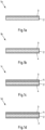
- Fig. 1a shows a two-layer aluminum composite material
- Fig. 1b a three-layer and Figs. 1c and 1d show a four-layer variant of the aluminum composite material according to the invention
- Fig. 1a 1 shows a sectional view of an exemplary embodiment of an aluminum material according to the invention in the form of an aluminum composite material 1a with a core layer 2 and a solder layer 3.
- the solder layer 3 can also be provided by a soldering foil F or a component K with a solder layer, so that after soldering the aluminum material is in direct, materially bonded contact with at least one solder layer 3, at least in some areas.
- solder layer 3 can also be provided by a soldering foil F or a component K with a solder layer, so that after soldering the aluminum material is in direct, materially bonded contact with at least one solder layer 3, at least in some areas.
- Fig. 1b shows an aluminum composite material 1b with an aluminum material according to the invention as a core layer 2, a solder layer 3 and an additional cladding layer 4.
- Fig. 1c illustrates a further exemplary embodiment of the aluminum material according to the invention in the form of a four-layer composite material 1c with a core layer 2 with a cladding layer 4 on both sides and an outer solder layer 3.
- the solder layer 3 according to an exemplary embodiment is provided by a solder foil or another component with a solder layer
- the aluminum material can After soldering, core layer 2 is in indirect, cohesive contact with the solder layer.
- the contact of the core layer 2 via the cladding layer 4 with the solder layer 3 is referred to as indirect material contact.
- the four-layer composite material 1c can also be provided by an aluminum material 2a with cladding layers 4 by providing the solder layer 3 via at least one separate component K after soldering.
- Fig. 1d shows a four-layer variant of the composite material 1d with a core layer 2, a cladding layer 4 arranged on the core layer 2 and two outer solder layers 3.
- an indirect cohesive contact after soldering between the aluminum material 2, here formed as the core layer of an aluminum composite material, and the Solder layer 3 can be provided.
- the solder layer is provided by a soldering foil or another component or part, the properties according to the invention can be achieved after soldering.
- All aluminum composite materials 1a, 1b, 1c and 1d shown can be used, for example, for the production of heat exchangers, structural components of motor vehicles or battery cooling plates.
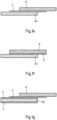
- Fig. 1e to Fig. 1g show exemplary embodiments in a sectional view in which the aluminum material 2a according to the invention has direct material contact in some areas after soldering.
- the solder layer is provided by a soldering foil F.
- the solder layer is provided by another component K.
- An aluminum material 2a with a plating layer on both sides for example made of an AA8079 alloy, which after soldering is at least partially in indirect contact with a solder layer provided as a soldering foil F Fig. 1g .
- the properties of the aluminum material according to the invention are presented and described based on the design as an aluminum composite material.
- the measured strength properties in particular are provided by the core alloy and thus by the aluminum material according to the invention of the exemplary embodiments.
- the aluminum composite materials 1a, 1b, 1c, 1d shown and the aluminum material 2a are usually present as a strip, which was produced, for example, by hot rolling or roll cladding, the total thickness can be 0.1 mm to 5 mm.
- Other manufacturing processes such as “simultaneous casting” followed by rolling are also conceivable for producing the strips.
- the core layer 2 or the aluminum material 2a consists of an aluminum alloy of the AlMgSi type and has a solidus temperature Tsol of at least 595 ° C, the aluminum composite material after soldering at at least 595 ° C with an average cooling rate of at least 0.5 ° C / s from 595 ° C to 200 ° C and a hot aging at 205 ° C for 45 minutes an increase in the yield strength R p0.2 compared to the state after soldering of at least 90 MPa, at least 110 MPa or preferably at least 120 MPa.
- the increase in the yield limit values in the aluminum composite material 1a, 1b, 1c, 1d and the aluminum material 2a is due to the hardening of the core layer 2 by the heat aging and enables economical provision of high-strength, soldered components, for example heat exchangers, battery cooling plates or structural components of a motor vehicle.
- This AlMgSi core alloy or alloy of the aluminum material has a low sensitivity to quenching and at the same time has a sufficiently high solidus temperature Tsol so that melting during soldering is avoided.
- Tsol solidus temperature
- the aluminum solder alloy of the solder layer preferably has the following composition in% by weight: 7.0 % ⁇ Si ⁇ 13.0 % , Fe ⁇ 0.8 % , Cu ⁇ 2.5 % , Mn ⁇ 0.1 % , Mg ⁇ 0.1 % , Cr ⁇ 0.1 % , Zn ⁇ 2.5 % , Ti ⁇ 0.3 % , Zr ⁇ 0.1 % , Rest Al and unavoidable impurities individually maximum 0.05%, in total maximum 0.15%.
- the solder layer consists of an aluminum solder alloy of type AA4045 or AA4343.
- the thickness of the solder layer 3 is typically 5% to 15% of the total thickness of the composite material.
- the aluminum composite material 1a can also be provided with a solder layer 3 on both sides (not shown here).
- a plating layer 4 can be applied, which has an aluminum alloy with a Mg content of ⁇ 0.1% by weight, preferably ⁇ 0.05% by weight, in order to improve the properties of the aluminum composite material 1 in terms of formability and solderability as well as corrosion protection.
- the plating layer 3 has an aluminum alloy with the following composition in% by weight: Si ⁇ 1.0 % , Fe ⁇ 2.0 % , preferably 0.1 % ⁇ Fe ⁇ 2.0 % , Cu ⁇ 0.3 % , Mn ⁇ 0.3 % , Mg ⁇ 0.1 % , preferably ⁇ 0.05 % , Cr ⁇ 0.1 % , Zn ⁇ 2.0 % , Ti ⁇ 0.3 % , Zr ⁇ 0.1 % , Rest Al and unavoidable impurities individually maximum 0.05%, in total maximum 0.15%.
- the cladding layer 3 preferably has 3% to 15% of the thickness of the entire aluminum composite material 1,1'.
- a cladding layer 4 between the core layer 2 and a solder layer 3 is arranged.
- a five-layer variant can be provided, with a cladding layer 4 lying on both sides of the core layer 2 and between the core layer 2 and an outer solder layer 3.
- composite materials 1-8 were produced with the layer structure listed in Table 1.
- the composite materials 1 and 2 have a cladding layer 4 on both sides of the core layer 2.
- a solder layer 3 is plated on a plating layer 4.
- the composite materials 3 to 6 have two layers and, in addition to the core layer, only have a one-sided solder layer 3.
- the composite material 7 is again designed with four layers, but only has a cladding layer 4 and a solder layer 3 on both sides on one side of the core layer 2.
- composite material 8 has a core layer 2 with a cladding layer attached thereto.
- the aluminum alloys of the core layer, the cladding layer and the solder layer with the chemical composition given in Table 2 were melted and cast as rolled ingots using the so-called direct chill casting process.
- the rolling ingots for the cladding layer and the solder layer were preheated to a rolling temperature in the range of 450°C to 525°C and hot-rolled to the required layer thickness.
- the cast ingot of the core material was subjected to homogenization annealing at 575 ° C with a holding time of 6 hours and subsequently assembled with the pre-rolled plates of the cladding layer and the solder material to form a so-called cladding package.
- This cladding package was preheated to a rolling temperature in the range of 450°C to 500°C and hot rolled to a thickness of 7mm.
- the test materials were subsequently cold-rolled to the final thicknesses shown in Table 1.
- Table 1 Sample no See/Ref Number of shifts core D (mm) Solder alloy No. / (thickness in %) Cladding layer (thickness in %) 1 See. 4 1 2.5 6/ (5%) 5/ (5%) 2 Req. 4 2 2.5 6 /(5%) 5 /(5%) 3 See. 2 3 1.5 6/ (5%) - 4 Req. 2 2 2.5 6 /(5%) 5 See. 2 3 1.5 6 /(5%) 6 See. 2 4 0.92 6 /(5%) 7 Req. 4 7 2.5 6 /(5%) 8(5%) 8th Req. 3 9 2.0 - 10 (7.5%)
- the solidus temperatures Tsol given in Table 2 were calculated for aluminum using the commercial software FactSage 7.0 and associated thermodynamic databases.
- Table 2 Chemical composition [% by weight] of the layers of the composite materials alloy function Si Fe Cu Mn Mg Cr Zn Ti Tsol 1 core 0.44 0.24 0.04 0.05 0.61 0.05 0.00 0.01 618°C 2 core 0.74 0.19 0.08 0.09 0.59 0.00 0.00 0.02 600°C 3 core 0.60 0.29 0.29 0.34 0.22 0.11 0.08 0.01 619°C 4 core 1.0 0.27 0.03 0.11 0.40 0.01 0.04 0.02 593°C 5 plating layer 0.07 0.87 0.00 0.021 0.00 0.00 0.01 0.01 650°C 6 solder layer 10.1 0.17 0.00 0.00 0.00 0.00 0.01 575°C 7 core 0.53 0.18 0.14 0.10 0.49 0.001 0.00 0.00 612°C 8th plating layer 0.03 0.24 - - - - - 9 core 0.64 0.16 0.10 0.07 0.61 0.01
- the samples were heated to 595 °C, representative of a typical soldering temperature, held at soldering temperature for 6 minutes and then cooled to 200 °C at the specified average cooling rate.
- the average cooling rate results from the temperature difference divided by the time required to reach 200 °C.
- hot aging is specified in the Condition column, where "45 min @ 205 °C” means hot aging for 45 minutes at 205 °C metal temperature. "14 d @ RT” indicates storage at room temperature for 14 days.
- yield strengths R p02 of more than 150 MPa were achieved during a short hot aging period of 45 minutes at 205 °C.
- the core layer has an Si content that is too high and therefore a solidus temperature Tsol that is too low, so that the composite material 6 tends to melt during soldering.
- Samples 1, 3 and 5 do not have core material compositions according to the invention. Samples 3 and 5 have Mn and Cr contents that are too high, so that due to the increased sensitivity to quenching, a sufficient increase in strength could not be achieved at the cooling rates that can be set in the soldering process.
- Table 3 Tensile test characteristics Sample no.
- Table 4 shows the strengths that can be achieved for different cooling rates using the example of aluminum composite material No. 2 according to the invention.
- Table 4 Tensile test characteristics vs.
- Cooling rate Soldering temperature and holding time Mean Cooling rate soldering temperature up to 200°C Hot aging
- Rm [MPa] A [%] 595°C 0.66°C/s 45min 185 243 16.0 6 mins 205°C 595°C 0.5°C/s 45min 165 230 17.0 6mm 205°C 595°C 0.33°C/s 45min 133 206 18.0 6 mins 205°C 595°C 0.16°C/s 45min 50 149 27.4 6 mins 205°C
- Fig. 2 shows a perspective view of the experimental setup for carrying out the bending tests to determine the maximum bending angle.
- the tests are based on the specification of the Association of the German Automotive Industry (VDA) 238-100.
- the experimental arrangement consists of a bending punch 14, which in the present case has a punch radius of 0.4 mm. Sample 15 was previously transverse to the Rolling direction cut out with a size of 250 mm x 68 mm.
- the sample 15 was then subjected to two annealing processes, with the first annealing simulating the typical temperature profile of CAB soldering, with the soldering temperature at 595°C with a holding time of 5 minutes and the cooling rate >0.5°C/sec up to 200°C being maintained , and the second annealing corresponds to a hot aging for 45 minutes at 205°C.
- the sample 15 was then cut to a size of 60 x 60 mm, with the edges being milled, and fed to the bending device.
- the force with which the bending punch bends the sample is measured and the bending process is ended after a maximum is exceeded and a decrease from this maximum by 60 N.
- the opening angle of the bent sample is then measured.
- the bending behavior of the sample is usually measured transversely to the rolling direction in order to obtain reliable information regarding the bending behavior when producing components with high forming requirements. In the present case, the bending behavior was tested transversely to the rolling direction in the solder-simulated and heat-aged condition, since the bending angle correlates with the ductility in the event of a crash.
- the bending punch 14 which as in Fig. 3 shown, runs parallel to the rolling direction, so that the bending line 18 also runs parallel to the rolling direction, with a force Fb the sample between two rollers 16,17 with a roller diameter of 30 mm, which are arranged at a distance of twice the sample thickness + 0.5 mm .
- the punch force Fb is measured. If the punch force Fb reaches a maximum and then drops by 60 N, the maximum achievable bending angle has been reached.
- the sample 15 is then removed from the bending device and the bending angle is as in Fig. 4 measured shown.
- ⁇ standard ⁇ Meas ⁇ d m 1 / 2 / d standard 1 / 2 calculated, where ⁇ norm is the standardized bending angle, ⁇ Mess is the measured bending angle, d norm is the standardized sheet thickness 2mm and d m is the measured sheet thickness.
- Table 5 shows the different variants that were examined. Table 5: Sample no Cf./Ref. Number of shifts Solder layer alloy (thickness in %) Core layer no. Cladding layer No., (thickness in %) 9 Req. 2 6 (5%) 2 - 10 Req. 4 6 (5%) 2 5, bilateral, (5% each)
- test sample No. 9 was plated on one side with a solder layer 4 and a layer thickness of 5%
- test sample 10 was plated on both sides with a plating layer 3 consisting of alloy No. 5 of type AA8079 with a layer thickness of 5% and on one side with a outer solder layer 4 made of alloy No. 6 is plated with a layer thickness of 5%.
- the plumb side was aligned towards the rollers 16, 17.
- the solder side of the aluminum composite material was aligned towards the stamp 14.
- sample 10 with a plating layer 3 allowed significantly higher bending angles than sample 9 made from conventional mono-AA6xxx alloys with a solder layer.
- the plating layer 3 therefore results in higher ductility in the event of a crash.
- the combination of a higher-strength core material with a ductility-promoting plating improves performance in the event of a crash, for example of a structural component.
- Table 6a Plumb side aligned with the rollers Sample no. Opening angle ⁇ standard [°] Bending angle ⁇ standard [°] 9 Req. 123 57 10 Req. 93 87 Sample no. Opening angle ⁇ norm [°] Bending angle ⁇ standard [°] 9 Req. 103 77 10 Req. 91 89
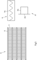
- a heat exchanger 10 a battery cooling plate 19 and a structural part of a motor vehicle 20 is shown in a schematic top view.
- the components of the heat exchanger for example the fins 11 of the heat exchanger 10, consist of a bare aluminum material 1a, 1b, 1c, 1d, 1e, 1f according to the invention described above or coated on both sides with an aluminum solder.
- the slats 11 are soldered to tubes 12 in a meandering shape, so that a large number of soldered connections are required.
- formed plates can also be used, which form cavities for guiding media.
- the tubes 12 can also be made from the aluminum composite material 1 according to the invention.
- a heat exchanger 10 can be used e.g. B. in a motor vehicle be exposed to corrosive substances, so that use of the aluminum composite material 1 according to the invention with a plating layer 3 is particularly advantageous.
- the battery cooling plate 19 is shown in a sectional view parallel to the plate plane.
- a battery cooling plate is usually a large-area component with meandering cooling channels 19a, which are closed by a soldered sheet metal as an upper part, not shown here.
- the parts of the battery cooling plate are preferably made of the aluminum composite material described in order to provide the necessary strength after soldering.
- a sectional view shows, as an example, a structural component 20 of a motor vehicle in the form of a closed, soldered profile consisting of a U-profile 20a and a striking plate 20b soldered thereto.
- These typical structural components of a motor vehicle can be provided with high strength aluminum composite material according to the invention.
- an aluminum material according to the invention can also be used, which, after soldering with a solder layer, is at least partially in direct or indirect cohesive contact with a solder layer, which has been provided, for example, by a soldering foil or a soldering component, in order to achieve the advantages according to the invention in relation to the properties of the soldered component Fig. 5 to provide.
Landscapes
- Engineering & Computer Science (AREA)
- Mechanical Engineering (AREA)
- Chemical & Material Sciences (AREA)
- Materials Engineering (AREA)
- Metallurgy (AREA)
- Organic Chemistry (AREA)
- Physics & Mathematics (AREA)
- Thermal Sciences (AREA)
- Crystallography & Structural Chemistry (AREA)
- Laminated Bodies (AREA)
- Pressure Welding/Diffusion-Bonding (AREA)
- Electric Connection Of Electric Components To Printed Circuits (AREA)
Priority Applications (1)
| Application Number | Priority Date | Filing Date | Title |
|---|---|---|---|
| EP23020526.2A EP4309839A3 (de) | 2020-04-08 | 2021-04-08 | Hochfester lotplattierter al-mg-si-aluminiumwerkstoff |
Applications Claiming Priority (2)
| Application Number | Priority Date | Filing Date | Title |
|---|---|---|---|
| EP20168844 | 2020-04-08 | ||
| PCT/EP2021/059143 WO2021204929A1 (de) | 2020-04-08 | 2021-04-08 | Hochfester lotplattierter al-mg-si-aluminiumwerkstoff |
Related Child Applications (1)
| Application Number | Title | Priority Date | Filing Date |
|---|---|---|---|
| EP23020526.2A Division EP4309839A3 (de) | 2020-04-08 | 2021-04-08 | Hochfester lotplattierter al-mg-si-aluminiumwerkstoff |
Publications (3)
| Publication Number | Publication Date |
|---|---|
| EP4132743A1 EP4132743A1 (de) | 2023-02-15 |
| EP4132743C0 EP4132743C0 (de) | 2023-11-29 |
| EP4132743B1 true EP4132743B1 (de) | 2023-11-29 |
Family
ID=70277259
Family Applications (2)
| Application Number | Title | Priority Date | Filing Date |
|---|---|---|---|
| EP21717430.9A Active EP4132743B1 (de) | 2020-04-08 | 2021-04-08 | Hochfester lotplattierter al-mg-si-aluminiumwerkstoff |
| EP23020526.2A Pending EP4309839A3 (de) | 2020-04-08 | 2021-04-08 | Hochfester lotplattierter al-mg-si-aluminiumwerkstoff |
Family Applications After (1)
| Application Number | Title | Priority Date | Filing Date |
|---|---|---|---|
| EP23020526.2A Pending EP4309839A3 (de) | 2020-04-08 | 2021-04-08 | Hochfester lotplattierter al-mg-si-aluminiumwerkstoff |
Country Status (8)
| Country | Link |
|---|---|
| US (1) | US20230078028A1 (pl) |
| EP (2) | EP4132743B1 (pl) |
| JP (1) | JP7493056B2 (pl) |
| KR (1) | KR102689028B1 (pl) |
| CN (1) | CN115427188B (pl) |
| HU (1) | HUE064969T2 (pl) |
| PL (1) | PL4132743T3 (pl) |
| WO (1) | WO2021204929A1 (pl) |
Families Citing this family (4)
| Publication number | Priority date | Publication date | Assignee | Title |
|---|---|---|---|---|
| US20250018508A1 (en) * | 2021-12-23 | 2025-01-16 | Arconic Technologies Llc | Brazing sheets, articles formed from brazing sheets, and methods of forming articles |
| FR3134584B1 (fr) | 2022-04-19 | 2025-05-16 | Constellium Neuf Brisach | Echangeur de chaleur à base d’un alliage d’aluminium obtenu par brasage |
| FR3137168B1 (fr) * | 2022-06-24 | 2024-08-02 | Valeo Systemes Thermiques | Plaque d’échange thermique pour pack batteries à plaque structurelle |
| CN116533607A (zh) * | 2023-04-24 | 2023-08-04 | 银邦金属复合材料股份有限公司 | 一种低淬火敏感性合金及其制备方法 |
Citations (11)
| Publication number | Priority date | Publication date | Assignee | Title |
|---|---|---|---|---|
| FR2185946A5 (pl) | 1972-05-23 | 1974-01-04 | Chausson Usines Sa | |
| JPH04178293A (ja) | 1990-11-08 | 1992-06-25 | Furukawa Alum Co Ltd | アルミニウムブレージングシート |
| EP0718072A1 (en) | 1994-12-19 | 1996-06-26 | Hoogovens Aluminium Walzprodukte GmbH | Brazing sheet |
| SE514234C2 (sv) | 1996-02-27 | 2001-01-29 | Sapa Heat Transfer Ab | Aluminiumlegering för lödda produkter |
| WO2002049789A1 (de) | 2000-12-21 | 2002-06-27 | Sms Demag Aktiengesellschaft | Profilbeeinflussbare giessrolle für das giessen von metallband in einer giessrollenanlage |
| WO2002049798A2 (en) | 2000-12-21 | 2002-06-27 | Alcoa Inc. | Multi-layer, heat treatable brazing sheet with aluminium interlayer |
| EP1712319A1 (de) | 2005-04-12 | 2006-10-18 | Behr GmbH & Co. KG | Anlage zum Herstellen von gelöteten Bauteilen mit einem Durchlauflötofen und einer statischen Abkühlzone |
| JP2011042823A (ja) | 2009-08-20 | 2011-03-03 | Furukawa-Sky Aluminum Corp | 時効硬化性アルミニウム合金ブレージングシート、その製造方法、およびそれを用いた熱交換器 |
| JP2014077179A (ja) | 2012-10-12 | 2014-05-01 | Uacj Corp | 高強度アルミニウム合金ブレージングシート及びその製造方法 |
| WO2017182145A1 (de) | 2016-04-19 | 2017-10-26 | Hydro Aluminium Rolled Products Gmbh | Aluminiumverbundwerkstoff mit korrosionsschutzschicht |
| WO2019164487A1 (en) | 2018-02-22 | 2019-08-29 | Arconic Inc. | Composite braze liner for low temperature brazing and high strength materials |
Family Cites Families (14)
| Publication number | Priority date | Publication date | Assignee | Title |
|---|---|---|---|---|
| CA2493037A1 (en) | 2002-07-24 | 2004-02-05 | Corus Aluminium Walzprodukte Gmbh | Brazing product and method of manufacturing a brazing product |
| EP1505163A3 (de) * | 2003-07-25 | 2005-02-16 | Hydro Aluminium Deutschland GmbH | Hochfeste Aluminium-Legierung für Wärmetauscher |
| US20100279143A1 (en) * | 2009-04-30 | 2010-11-04 | Kamat Rajeev G | Multi-alloy composite sheet for automotive panels |
| US8247083B2 (en) * | 2010-05-18 | 2012-08-21 | Kobe Steel, Ltd. | Aluminium alloy brazing sheet |
| JP5466080B2 (ja) | 2010-05-18 | 2014-04-09 | 株式会社神戸製鋼所 | アルミニウム合金ブレージングシート |
| JP5537256B2 (ja) | 2010-05-18 | 2014-07-02 | 株式会社神戸製鋼所 | アルミニウム合金ブレージングシート |
| FR2979576B1 (fr) * | 2011-09-02 | 2018-07-20 | Constellium France | Tole plaquee pour carrosserie automobile |
| EP2570257B1 (de) * | 2011-09-15 | 2021-05-12 | Hydro Aluminium Rolled Products GmbH | Aluminiumverbundwerkstoff mit AlMgSi-Kernlegierungsschicht |
| CN104080935A (zh) * | 2011-11-02 | 2014-10-01 | 株式会社Uacj | 成型加工用的铝合金包层材料 |
| EP2846961B1 (en) * | 2012-05-10 | 2023-04-12 | Arconic Technologies LLC | Tube for a heat exchanger |
| JP5756439B2 (ja) * | 2012-07-31 | 2015-07-29 | 株式会社神戸製鋼所 | アルミニウム合金ブレージングシート |
| JP5339560B1 (ja) * | 2012-11-14 | 2013-11-13 | 古河スカイ株式会社 | アルミニウム合金ブレージングシート及びその製造方法 |
| HUE042051T2 (hu) * | 2013-07-05 | 2019-06-28 | Hydro Aluminium Rolled Prod | Alumínium összetett anyag, mely belefektetett szilárd réteget tartalmaz |
| PL3359326T3 (pl) * | 2015-10-05 | 2019-05-31 | Hydro Aluminium Rolled Prod | Aluminiowy materiał kompozytowy do stosowania w sposobach termicznego łączenia bez użycia topnika i sposób jego wytwarzania |
-
2021
- 2021-04-08 KR KR1020227035538A patent/KR102689028B1/ko active Active
- 2021-04-08 JP JP2022561461A patent/JP7493056B2/ja active Active
- 2021-04-08 EP EP21717430.9A patent/EP4132743B1/de active Active
- 2021-04-08 HU HUE21717430A patent/HUE064969T2/hu unknown
- 2021-04-08 CN CN202180027390.XA patent/CN115427188B/zh active Active
- 2021-04-08 WO PCT/EP2021/059143 patent/WO2021204929A1/de not_active Ceased
- 2021-04-08 PL PL21717430.9T patent/PL4132743T3/pl unknown
- 2021-04-08 EP EP23020526.2A patent/EP4309839A3/de active Pending
-
2022
- 2022-09-15 US US17/945,656 patent/US20230078028A1/en active Pending
Patent Citations (11)
| Publication number | Priority date | Publication date | Assignee | Title |
|---|---|---|---|---|
| FR2185946A5 (pl) | 1972-05-23 | 1974-01-04 | Chausson Usines Sa | |
| JPH04178293A (ja) | 1990-11-08 | 1992-06-25 | Furukawa Alum Co Ltd | アルミニウムブレージングシート |
| EP0718072A1 (en) | 1994-12-19 | 1996-06-26 | Hoogovens Aluminium Walzprodukte GmbH | Brazing sheet |
| SE514234C2 (sv) | 1996-02-27 | 2001-01-29 | Sapa Heat Transfer Ab | Aluminiumlegering för lödda produkter |
| WO2002049789A1 (de) | 2000-12-21 | 2002-06-27 | Sms Demag Aktiengesellschaft | Profilbeeinflussbare giessrolle für das giessen von metallband in einer giessrollenanlage |
| WO2002049798A2 (en) | 2000-12-21 | 2002-06-27 | Alcoa Inc. | Multi-layer, heat treatable brazing sheet with aluminium interlayer |
| EP1712319A1 (de) | 2005-04-12 | 2006-10-18 | Behr GmbH & Co. KG | Anlage zum Herstellen von gelöteten Bauteilen mit einem Durchlauflötofen und einer statischen Abkühlzone |
| JP2011042823A (ja) | 2009-08-20 | 2011-03-03 | Furukawa-Sky Aluminum Corp | 時効硬化性アルミニウム合金ブレージングシート、その製造方法、およびそれを用いた熱交換器 |
| JP2014077179A (ja) | 2012-10-12 | 2014-05-01 | Uacj Corp | 高強度アルミニウム合金ブレージングシート及びその製造方法 |
| WO2017182145A1 (de) | 2016-04-19 | 2017-10-26 | Hydro Aluminium Rolled Products Gmbh | Aluminiumverbundwerkstoff mit korrosionsschutzschicht |
| WO2019164487A1 (en) | 2018-02-22 | 2019-08-29 | Arconic Inc. | Composite braze liner for low temperature brazing and high strength materials |
Non-Patent Citations (16)
| Title |
|---|
| "FactStage 8.3", 24 June 2024 (2024-06-24), XP093224434, Retrieved from the Internet <URL:https://factsage.com/> |
| AFNOR: " NF EN 515 - Aluminium et alliages d'aluminium — Produits corroyés — Désignation des états métallurgiques", NORMES FRANCAISES., AFNOR, 15 April 2017 (2017-04-15), Paris, FR, pages 1 - 26, XP093224552, ISSN: 0335-3931 |
| AFSETH ANDREAS: " Development of high strength sheet crash alloy for BIW structures", MATERIALS IN CAR BODY ENGINEERING 2013, 8 May 2013 (2013-05-08) - 8 May 2013 (2013-05-08), XP093224559 |
| ANONYMOUS: "Demi produits aluminium", PECHINEY RHENALU, 1 May 1997 (1997-05-01), pages 14, 15, 28 - 29, XP055774979, [retrieved on 20210211] |
| ANONYMOUS: "Heat Exchanger Aluminum", ALERIS CORPORATION, 1 January 2014 (2014-01-01), pages 1 - 12, XP093219061, Retrieved from the Internet <URL:https://imstur.com/img/sTa26pja.pdf> |
| ASTRID MAGNUSSON, TORKEL STENQVIST: "MULTICLAD - A WAY TO HANDLE MG CONTAINING ALLOYS IN CONTROLLED ATMOSPHERE BRAZING", 1999 INTERNATIONAL INVITATIONAL ALUMINIUM BRAZING SEMINAR; OCTOBER 1999; DEARBORN, MI, USA, 1 October 1999 (1999-10-01), pages 1 - 14, XP009559932 |
| D13 - D18 - Usage antérieur : various documents |
| D4 - ALUMINIUM BRAZING - NEWS, KNOWLEDGE & TECHNOLOGY: "Cladding Alloys", 29 September 2010 (2010-09-29), Retrieved from the Internet <URL:https://www.aluminium-brazing.com/2010/09/29/cladding-alloys/> [retrieved on 20190910] |
| EDWARD GHALI: "CORROSION RESISTANCE OF ALUMINIUM AND MAGNESIUM ALLOYS. UNDERSTANDING, PERFORMANCE, AND TESTING", 26 April 2010, JOHN WILEY AND SONS INC. , NEW JERSEY , ISBN: 978-0-471-71576-4, article EDWARD GHALI: "General, Galvanic, and Localized Corrosion of Aluminum and Its Alloys", pages: 176 - 214, XP009557736 |
| EUROPEAN ALUMINIUM ASSOCIATION: "Applications – Power train – Heat exchangers", 1 January 2011 (2011-01-01), pages 1 - 46, XP093219065, Retrieved from the Internet <URL:https://european-aluminium.eu/wp-content/uploads/2022/11/aam-applications-power-train-7-heat-exchangers.pdf> |
| GRÄNGES: "Multiclad tube product for CAB brochure", 5 November 2018 (2018-11-05), XP009558275, Retrieved from the Internet <URL:<URL:http://www.granges.com/products-innovaton/our-products/product-brochure/multiclad-tube-product/>> |
| HUI ZHAO, STEFAN EBEL AND PEGA HRNJAK: "Controlled atmosphere brazing of aluminium heat exchangers", WELDING JOURNAL., AMERICAN WELDING SOCIETY, vol. 92, no. 2, 1 February 2013 (2013-02-01), US , pages 44 - 46, XP001581616, ISSN: 0043-2296 |
| JOHANSSON H, ET AL: "Controlled atmosphere brazing of heat treatable alloys with cesium flux C599/013/2003", IMECHE, 1 January 2003 (2003-01-01), pages 1 - 12, XP093219002, Retrieved from the Internet <URL:https://www.aluminium-brazing.com/sponsor/nocolok/Files/PDFs/Publications_05.pdf> |
| STENQVIST, TORKEL: "A New High Strength Aluminium Alloy for Controlled Atmosphere Brazing", PROCEEDINGS OF THE 2001 VEHICLE THERMAL MANAGEMENT SYSTEMS CONFERENCE : [NASHVILLE, TENNESSEE, MAY 14 - 17, 2001], SOCIETY OF AUTOMOTIVE ENGINEERS, WARRENDALE, US, 14 May 2001 (2001-05-14) - 17 May 2001 (2001-05-17), Warrendale, US, pages 325 - 331, XP009558730, ISBN: 0-7680-0779-8, DOI: 10.4271/2001-01-1727 |
| THE ALUMINUN ASSOCIATION: "International Alloy Designations and Chemical Composition Limits for Wrought Aluminum and Wrought Aluminum Alloys", THE ALUMINUN ASSOCIATION, 1 August 2018 (2018-08-01), pages 1 - 45, XP093219020, ISSN: 2377-6692, Retrieved from the Internet <URL:https://www.aluminum.org/sites/default/files/2021-10/Teal%20Sheet.pdf> |
| TORKEL STENQVIST, ANNIKA MOBERG, DOUG HAWKSWORTH: "Brazeability of FA7827 multiclad, evaluated with a simple test", 2000 INTERNATIONAL INVITATIONAL ALUMINIUM BRAZING SEMINAR; OCTOBER 2000, DEARBORN, MI, USA, 1 October 2000 (2000-10-01), pages 1 - 9, XP009559931 |
Also Published As
| Publication number | Publication date |
|---|---|
| EP4132743C0 (de) | 2023-11-29 |
| WO2021204929A1 (de) | 2021-10-14 |
| JP7493056B2 (ja) | 2024-05-30 |
| US20230078028A1 (en) | 2023-03-16 |
| KR20220148291A (ko) | 2022-11-04 |
| PL4132743T3 (pl) | 2024-05-27 |
| EP4132743A1 (de) | 2023-02-15 |
| KR102689028B1 (ko) | 2024-07-29 |
| CN115427188B (zh) | 2023-12-19 |
| JP2023511790A (ja) | 2023-03-22 |
| HUE064969T2 (hu) | 2024-04-28 |
| EP4309839A3 (de) | 2024-05-08 |
| CN115427188A (zh) | 2022-12-02 |
| EP4309839A2 (de) | 2024-01-24 |
Similar Documents
| Publication | Publication Date | Title |
|---|---|---|
| EP3026134B1 (de) | Wärmetauscher, verwendung einer aluminiumlegierung und eines aluminiumbands sowie verfahren zur herstellung eines aluminiumbands | |
| DE60021619T2 (de) | Hartlötblech | |
| DE60004398T2 (de) | Aluminiumlotlegierung | |
| EP4309839A2 (de) | Hochfester lotplattierter al-mg-si-aluminiumwerkstoff | |
| EP1730320B1 (de) | Herstellungsverfahren eines aluminiumlegierungsbandes oder -bleches für wärmetauscher | |
| DE202017100499U1 (de) | Aluminium Multi-Schicht Hartlötblechprodukt | |
| DE10116636C2 (de) | Verfahren zur Herstellung von AIMn-Bändern oder Blechen | |
| EP2888382B1 (de) | Gegen interkristalline korrosion beständiges aluminiumlegierungsband und verfahren zu seiner herstellung | |
| DE112013000740T5 (de) | Hoch korrosionsbeständiges Hartlötblech aus Aluminiumlegierung und daraus hergestellte kanalbildende Komponente für einen Fahrzeugwärmetauscher | |
| EP2370229B1 (de) | Mehrschichtiges aluminiumband zum löten, lötbauteil, herstellungsverfahren und wärmetauscher und verwendung | |
| AT521441B1 (de) | Aluminium-Hartlotblechmaterial, das zum flussmittelfreien Löten in einer Schutzgasatmosphäre geeignet ist | |
| DE112017001484T5 (de) | Aluminiumlegierungswerkstoff für wärmetauscher und verfahren zu dessen herstellung sowie plattierter aluminiumlegierungswerkstoff für wärmetauscher und verfahren zu dessen herstellung | |
| EP2888383B1 (de) | Hochumformbares und ik-beständiges almg-band | |
| EP2039790A1 (de) | Korrosionsschutzschicht | |
| EP2302087B1 (de) | Fahrwerkteil aus AL-Verbundwerkstoff | |
| EP2302086B1 (de) | Korrosionsbeständiger Aluminiumverbundwerkstoff für eine Fahrzeugkarosserie | |
| DE60206099T2 (de) | Hochfeste Aluminiumlegierung geeignet für ein Rohr | |
| CH700835B1 (de) | Aluminium-Verbundwalzblechprodukt. | |
| EP1505163A2 (de) | Hochfeste Aluminium-Legierung für Wärmetauscher | |
| DE112022003734T5 (de) | Aluminiumlegierungshartlotblech und verfahren zum herstellen desselben | |
| DE69901905T2 (de) | Mit einer Aluminium-Legierung plattiertes Material für einen Wärmetauscher mit hoher Festigkeit und guter Korrosionsbeständigkeit | |
| DE112022004260T5 (de) | Aluminiumlegierungsplattierungsmaterial für wärmetauscher |
Legal Events
| Date | Code | Title | Description |
|---|---|---|---|
| STAA | Information on the status of an ep patent application or granted ep patent |
Free format text: STATUS: UNKNOWN |
|
| STAA | Information on the status of an ep patent application or granted ep patent |
Free format text: STATUS: THE INTERNATIONAL PUBLICATION HAS BEEN MADE |
|
| PUAI | Public reference made under article 153(3) epc to a published international application that has entered the european phase |
Free format text: ORIGINAL CODE: 0009012 |
|
| STAA | Information on the status of an ep patent application or granted ep patent |
Free format text: STATUS: REQUEST FOR EXAMINATION WAS MADE |
|
| 17P | Request for examination filed |
Effective date: 20220915 |
|
| AK | Designated contracting states |
Kind code of ref document: A1 Designated state(s): AL AT BE BG CH CY CZ DE DK EE ES FI FR GB GR HR HU IE IS IT LI LT LU LV MC MK MT NL NO PL PT RO RS SE SI SK SM TR |
|
| GRAP | Despatch of communication of intention to grant a patent |
Free format text: ORIGINAL CODE: EPIDOSNIGR1 |
|
| STAA | Information on the status of an ep patent application or granted ep patent |
Free format text: STATUS: GRANT OF PATENT IS INTENDED |
|
| DAV | Request for validation of the european patent (deleted) | ||
| DAX | Request for extension of the european patent (deleted) | ||
| INTG | Intention to grant announced |
Effective date: 20230612 |
|
| GRAS | Grant fee paid |
Free format text: ORIGINAL CODE: EPIDOSNIGR3 |
|
| GRAA | (expected) grant |
Free format text: ORIGINAL CODE: 0009210 |
|
| STAA | Information on the status of an ep patent application or granted ep patent |
Free format text: STATUS: THE PATENT HAS BEEN GRANTED |
|
| AK | Designated contracting states |
Kind code of ref document: B1 Designated state(s): AL AT BE BG CH CY CZ DE DK EE ES FI FR GB GR HR HU IE IS IT LI LT LU LV MC MK MT NL NO PL PT RO RS SE SI SK SM TR |
|
| REG | Reference to a national code |
Ref country code: GB Ref legal event code: FG4D Free format text: NOT ENGLISH |
|
| REG | Reference to a national code |
Ref country code: CH Ref legal event code: EP |
|
| REG | Reference to a national code |
Ref country code: DE Ref legal event code: R096 Ref document number: 502021002090 Country of ref document: DE |
|
| REG | Reference to a national code |
Ref country code: IE Ref legal event code: FG4D Free format text: LANGUAGE OF EP DOCUMENT: GERMAN |
|
| U01 | Request for unitary effect filed |
Effective date: 20231219 |
|
| U07 | Unitary effect registered |
Designated state(s): AT BE BG DE DK EE FI FR IT LT LU LV MT NL PT SE SI Effective date: 20240108 |
|
| PG25 | Lapsed in a contracting state [announced via postgrant information from national office to epo] |
Ref country code: GR Free format text: LAPSE BECAUSE OF FAILURE TO SUBMIT A TRANSLATION OF THE DESCRIPTION OR TO PAY THE FEE WITHIN THE PRESCRIBED TIME-LIMIT Effective date: 20240301 |
|
| PG25 | Lapsed in a contracting state [announced via postgrant information from national office to epo] |
Ref country code: IS Free format text: LAPSE BECAUSE OF FAILURE TO SUBMIT A TRANSLATION OF THE DESCRIPTION OR TO PAY THE FEE WITHIN THE PRESCRIBED TIME-LIMIT Effective date: 20240329 |
|
| PG25 | Lapsed in a contracting state [announced via postgrant information from national office to epo] |
Ref country code: ES Free format text: LAPSE BECAUSE OF FAILURE TO SUBMIT A TRANSLATION OF THE DESCRIPTION OR TO PAY THE FEE WITHIN THE PRESCRIBED TIME-LIMIT Effective date: 20231129 |
|
| REG | Reference to a national code |
Ref country code: HU Ref legal event code: AG4A Ref document number: E064969 Country of ref document: HU |
|
| PG25 | Lapsed in a contracting state [announced via postgrant information from national office to epo] |
Ref country code: IS Free format text: LAPSE BECAUSE OF FAILURE TO SUBMIT A TRANSLATION OF THE DESCRIPTION OR TO PAY THE FEE WITHIN THE PRESCRIBED TIME-LIMIT Effective date: 20240329 Ref country code: GR Free format text: LAPSE BECAUSE OF FAILURE TO SUBMIT A TRANSLATION OF THE DESCRIPTION OR TO PAY THE FEE WITHIN THE PRESCRIBED TIME-LIMIT Effective date: 20240301 Ref country code: ES Free format text: LAPSE BECAUSE OF FAILURE TO SUBMIT A TRANSLATION OF THE DESCRIPTION OR TO PAY THE FEE WITHIN THE PRESCRIBED TIME-LIMIT Effective date: 20231129 |
|
| U20 | Renewal fee for the european patent with unitary effect paid |
Year of fee payment: 4 Effective date: 20240327 |
|
| PG25 | Lapsed in a contracting state [announced via postgrant information from national office to epo] |
Ref country code: RS Free format text: LAPSE BECAUSE OF FAILURE TO SUBMIT A TRANSLATION OF THE DESCRIPTION OR TO PAY THE FEE WITHIN THE PRESCRIBED TIME-LIMIT Effective date: 20231129 Ref country code: NO Free format text: LAPSE BECAUSE OF FAILURE TO SUBMIT A TRANSLATION OF THE DESCRIPTION OR TO PAY THE FEE WITHIN THE PRESCRIBED TIME-LIMIT Effective date: 20240229 Ref country code: HR Free format text: LAPSE BECAUSE OF FAILURE TO SUBMIT A TRANSLATION OF THE DESCRIPTION OR TO PAY THE FEE WITHIN THE PRESCRIBED TIME-LIMIT Effective date: 20231129 |
|
| PG25 | Lapsed in a contracting state [announced via postgrant information from national office to epo] |
Ref country code: CZ Free format text: LAPSE BECAUSE OF FAILURE TO SUBMIT A TRANSLATION OF THE DESCRIPTION OR TO PAY THE FEE WITHIN THE PRESCRIBED TIME-LIMIT Effective date: 20231129 |
|
| PG25 | Lapsed in a contracting state [announced via postgrant information from national office to epo] |
Ref country code: SK Free format text: LAPSE BECAUSE OF FAILURE TO SUBMIT A TRANSLATION OF THE DESCRIPTION OR TO PAY THE FEE WITHIN THE PRESCRIBED TIME-LIMIT Effective date: 20231129 |
|
| PG25 | Lapsed in a contracting state [announced via postgrant information from national office to epo] |
Ref country code: SM Free format text: LAPSE BECAUSE OF FAILURE TO SUBMIT A TRANSLATION OF THE DESCRIPTION OR TO PAY THE FEE WITHIN THE PRESCRIBED TIME-LIMIT Effective date: 20231129 Ref country code: SK Free format text: LAPSE BECAUSE OF FAILURE TO SUBMIT A TRANSLATION OF THE DESCRIPTION OR TO PAY THE FEE WITHIN THE PRESCRIBED TIME-LIMIT Effective date: 20231129 Ref country code: CZ Free format text: LAPSE BECAUSE OF FAILURE TO SUBMIT A TRANSLATION OF THE DESCRIPTION OR TO PAY THE FEE WITHIN THE PRESCRIBED TIME-LIMIT Effective date: 20231129 |
|
| REG | Reference to a national code |
Ref country code: DE Ref legal event code: R026 Ref document number: 502021002090 Country of ref document: DE |
|
| PLBI | Opposition filed |
Free format text: ORIGINAL CODE: 0009260 |
|
| PLAB | Opposition data, opponent's data or that of the opponent's representative modified |
Free format text: ORIGINAL CODE: 0009299OPPO |
|
| PLAX | Notice of opposition and request to file observation + time limit sent |
Free format text: ORIGINAL CODE: EPIDOSNOBS2 |
|
| 26 | Opposition filed |
Opponent name: GRAENGES AB Effective date: 20240828 Opponent name: C-TEC CONSTELLIUM TECHNOLOGY CENTER /CONSTELLIUM NEUF-BRISACH Effective date: 20240826 |
|
| R26 | Opposition filed (corrected) |
Opponent name: GRAENGES AB Effective date: 20240828 Opponent name: C-TEC CONSTELLIUM TECHNOLOGY CENTER /CONSTELLIUM NEUF-BRISACH Effective date: 20240826 |
|
| PG25 | Lapsed in a contracting state [announced via postgrant information from national office to epo] |
Ref country code: MC Free format text: LAPSE BECAUSE OF FAILURE TO SUBMIT A TRANSLATION OF THE DESCRIPTION OR TO PAY THE FEE WITHIN THE PRESCRIBED TIME-LIMIT Effective date: 20231129 |
|
| PG25 | Lapsed in a contracting state [announced via postgrant information from national office to epo] |
Ref country code: MC Free format text: LAPSE BECAUSE OF FAILURE TO SUBMIT A TRANSLATION OF THE DESCRIPTION OR TO PAY THE FEE WITHIN THE PRESCRIBED TIME-LIMIT Effective date: 20231129 |
|
| REG | Reference to a national code |
Ref country code: CH Ref legal event code: PL |
|
| PLAF | Information modified related to communication of a notice of opposition and request to file observations + time limit |
Free format text: ORIGINAL CODE: EPIDOSCOBS2 |
|
| PG25 | Lapsed in a contracting state [announced via postgrant information from national office to epo] |
Ref country code: CH Free format text: LAPSE BECAUSE OF NON-PAYMENT OF DUE FEES Effective date: 20240430 |
|
| PLBB | Reply of patent proprietor to notice(s) of opposition received |
Free format text: ORIGINAL CODE: EPIDOSNOBS3 |
|
| PG25 | Lapsed in a contracting state [announced via postgrant information from national office to epo] |
Ref country code: IE Free format text: LAPSE BECAUSE OF NON-PAYMENT OF DUE FEES Effective date: 20240408 |
|
| U20 | Renewal fee for the european patent with unitary effect paid |
Year of fee payment: 5 Effective date: 20250424 |
|
| PGFP | Annual fee paid to national office [announced via postgrant information from national office to epo] |
Ref country code: HU Payment date: 20250312 Year of fee payment: 5 |
|
| PG25 | Lapsed in a contracting state [announced via postgrant information from national office to epo] |
Ref country code: CY Free format text: LAPSE BECAUSE OF FAILURE TO SUBMIT A TRANSLATION OF THE DESCRIPTION OR TO PAY THE FEE WITHIN THE PRESCRIBED TIME-LIMIT; INVALID AB INITIO Effective date: 20210408 |
|
| GBPC | Gb: european patent ceased through non-payment of renewal fee |
Effective date: 20250408 |
|
| PG25 | Lapsed in a contracting state [announced via postgrant information from national office to epo] |
Ref country code: GB Free format text: LAPSE BECAUSE OF NON-PAYMENT OF DUE FEES Effective date: 20250408 |
|
| PGFP | Annual fee paid to national office [announced via postgrant information from national office to epo] |
Ref country code: RO Payment date: 20260302 Year of fee payment: 6 |
|
| PGFP | Annual fee paid to national office [announced via postgrant information from national office to epo] |
Ref country code: PL Payment date: 20260317 Year of fee payment: 6 |