EP4131773B1 - Photovoltaic frame, photovoltaic module and method for manufacturing photovoltaic frame - Google Patents
Photovoltaic frame, photovoltaic module and method for manufacturing photovoltaic frame Download PDFInfo
- Publication number
- EP4131773B1 EP4131773B1 EP22198520.3A EP22198520A EP4131773B1 EP 4131773 B1 EP4131773 B1 EP 4131773B1 EP 22198520 A EP22198520 A EP 22198520A EP 4131773 B1 EP4131773 B1 EP 4131773B1
- Authority
- EP
- European Patent Office
- Prior art keywords
- edge portion
- support portion
- side edge
- photovoltaic frame
- photovoltaic
- Prior art date
- Legal status (The legal status is an assumption and is not a legal conclusion. Google has not performed a legal analysis and makes no representation as to the accuracy of the status listed.)
- Active
Links
- 238000000034 method Methods 0.000 title claims description 26
- 238000004519 manufacturing process Methods 0.000 title description 49
- 239000000463 material Substances 0.000 claims description 163
- 229910000975 Carbon steel Inorganic materials 0.000 claims description 123
- 239000010962 carbon steel Substances 0.000 claims description 123
- 239000011241 protective layer Substances 0.000 claims description 59
- 239000010410 layer Substances 0.000 claims description 31
- 230000008569 process Effects 0.000 claims description 13
- 239000002313 adhesive film Substances 0.000 claims description 6
- 239000000956 alloy Substances 0.000 claims description 5
- 229910045601 alloy Inorganic materials 0.000 claims description 4
- 238000007747 plating Methods 0.000 claims description 4
- 238000005452 bending Methods 0.000 description 53
- 230000003014 reinforcing effect Effects 0.000 description 18
- 238000010586 diagram Methods 0.000 description 17
- 238000005187 foaming Methods 0.000 description 17
- 229910052799 carbon Inorganic materials 0.000 description 14
- 239000000126 substance Substances 0.000 description 13
- OKTJSMMVPCPJKN-UHFFFAOYSA-N Carbon Chemical compound [C] OKTJSMMVPCPJKN-UHFFFAOYSA-N 0.000 description 12
- QVGXLLKOCUKJST-UHFFFAOYSA-N atomic oxygen Chemical compound [O] QVGXLLKOCUKJST-UHFFFAOYSA-N 0.000 description 12
- 229910052760 oxygen Inorganic materials 0.000 description 12
- 239000001301 oxygen Substances 0.000 description 12
- XLYOFNOQVPJJNP-UHFFFAOYSA-N water Substances O XLYOFNOQVPJJNP-UHFFFAOYSA-N 0.000 description 12
- 238000012545 processing Methods 0.000 description 11
- 238000013461 design Methods 0.000 description 9
- XUIMIQQOPSSXEZ-UHFFFAOYSA-N Silicon Chemical compound [Si] XUIMIQQOPSSXEZ-UHFFFAOYSA-N 0.000 description 7
- 229910052782 aluminium Inorganic materials 0.000 description 7
- XAGFODPZIPBFFR-UHFFFAOYSA-N aluminium Chemical compound [Al] XAGFODPZIPBFFR-UHFFFAOYSA-N 0.000 description 7
- 229920002635 polyurethane Polymers 0.000 description 7
- 239000004814 polyurethane Substances 0.000 description 7
- 229910052710 silicon Inorganic materials 0.000 description 7
- 239000010703 silicon Substances 0.000 description 7
- 238000003466 welding Methods 0.000 description 7
- PWHULOQIROXLJO-UHFFFAOYSA-N Manganese Chemical compound [Mn] PWHULOQIROXLJO-UHFFFAOYSA-N 0.000 description 6
- OAICVXFJPJFONN-UHFFFAOYSA-N Phosphorus Chemical compound [P] OAICVXFJPJFONN-UHFFFAOYSA-N 0.000 description 6
- 229910000831 Steel Inorganic materials 0.000 description 6
- NINIDFKCEFEMDL-UHFFFAOYSA-N Sulfur Chemical compound [S] NINIDFKCEFEMDL-UHFFFAOYSA-N 0.000 description 6
- 230000006872 improvement Effects 0.000 description 6
- 229910052698 phosphorus Inorganic materials 0.000 description 6
- 239000011574 phosphorus Substances 0.000 description 6
- 239000010959 steel Substances 0.000 description 6
- 229910052717 sulfur Inorganic materials 0.000 description 6
- 239000011593 sulfur Substances 0.000 description 6
- 238000005260 corrosion Methods 0.000 description 5
- 230000007797 corrosion Effects 0.000 description 5
- 239000011521 glass Substances 0.000 description 5
- 229920003023 plastic Polymers 0.000 description 5
- 239000004033 plastic Substances 0.000 description 5
- 239000000243 solution Substances 0.000 description 5
- 239000000853 adhesive Substances 0.000 description 4
- 230000001070 adhesive effect Effects 0.000 description 4
- 238000005516 engineering process Methods 0.000 description 4
- 230000006870 function Effects 0.000 description 4
- 230000001788 irregular Effects 0.000 description 4
- 239000002356 single layer Substances 0.000 description 4
- RNFJDJUURJAICM-UHFFFAOYSA-N 2,2,4,4,6,6-hexaphenoxy-1,3,5-triaza-2$l^{5},4$l^{5},6$l^{5}-triphosphacyclohexa-1,3,5-triene Chemical compound N=1P(OC=2C=CC=CC=2)(OC=2C=CC=CC=2)=NP(OC=2C=CC=CC=2)(OC=2C=CC=CC=2)=NP=1(OC=1C=CC=CC=1)OC1=CC=CC=C1 RNFJDJUURJAICM-UHFFFAOYSA-N 0.000 description 3
- 230000009471 action Effects 0.000 description 3
- 238000005520 cutting process Methods 0.000 description 3
- 229910003460 diamond Inorganic materials 0.000 description 3
- 239000010432 diamond Substances 0.000 description 3
- 239000003063 flame retardant Substances 0.000 description 3
- 230000001965 increasing effect Effects 0.000 description 3
- 229910052748 manganese Inorganic materials 0.000 description 3
- 239000011572 manganese Substances 0.000 description 3
- 230000002035 prolonged effect Effects 0.000 description 3
- 239000006104 solid solution Substances 0.000 description 3
- 238000005728 strengthening Methods 0.000 description 3
- XKRFYHLGVUSROY-UHFFFAOYSA-N Argon Chemical compound [Ar] XKRFYHLGVUSROY-UHFFFAOYSA-N 0.000 description 2
- XEEYBQQBJWHFJM-UHFFFAOYSA-N Iron Chemical compound [Fe] XEEYBQQBJWHFJM-UHFFFAOYSA-N 0.000 description 2
- UQSXHKLRYXJYBZ-UHFFFAOYSA-N Iron oxide Chemical compound [Fe]=O UQSXHKLRYXJYBZ-UHFFFAOYSA-N 0.000 description 2
- 229920005830 Polyurethane Foam Polymers 0.000 description 2
- 230000009286 beneficial effect Effects 0.000 description 2
- 238000003490 calendering Methods 0.000 description 2
- 150000001721 carbon Chemical class 0.000 description 2
- 238000011161 development Methods 0.000 description 2
- 230000002708 enhancing effect Effects 0.000 description 2
- 239000003365 glass fiber Substances 0.000 description 2
- 238000009434 installation Methods 0.000 description 2
- 229910052751 metal Inorganic materials 0.000 description 2
- 239000002184 metal Substances 0.000 description 2
- 238000000465 moulding Methods 0.000 description 2
- 239000011496 polyurethane foam Substances 0.000 description 2
- 238000003825 pressing Methods 0.000 description 2
- 150000003839 salts Chemical class 0.000 description 2
- 239000007921 spray Substances 0.000 description 2
- 229920006305 unsaturated polyester Polymers 0.000 description 2
- 229910000838 Al alloy Inorganic materials 0.000 description 1
- 239000002033 PVDF binder Substances 0.000 description 1
- 239000004698 Polyethylene Substances 0.000 description 1
- 238000005275 alloying Methods 0.000 description 1
- SNAAJJQQZSMGQD-UHFFFAOYSA-N aluminum magnesium Chemical compound [Mg].[Al] SNAAJJQQZSMGQD-UHFFFAOYSA-N 0.000 description 1
- 238000004458 analytical method Methods 0.000 description 1
- 229910052786 argon Inorganic materials 0.000 description 1
- 239000010426 asphalt Substances 0.000 description 1
- 150000001875 compounds Chemical class 0.000 description 1
- 239000004567 concrete Substances 0.000 description 1
- 238000012938 design process Methods 0.000 description 1
- 230000000694 effects Effects 0.000 description 1
- 239000000945 filler Substances 0.000 description 1
- 238000010438 heat treatment Methods 0.000 description 1
- 230000002209 hydrophobic effect Effects 0.000 description 1
- 238000005286 illumination Methods 0.000 description 1
- 239000003999 initiator Substances 0.000 description 1
- 229910052742 iron Inorganic materials 0.000 description 1
- WPBNNNQJVZRUHP-UHFFFAOYSA-L manganese(2+);methyl n-[[2-(methoxycarbonylcarbamothioylamino)phenyl]carbamothioyl]carbamate;n-[2-(sulfidocarbothioylamino)ethyl]carbamodithioate Chemical compound [Mn+2].[S-]C(=S)NCCNC([S-])=S.COC(=O)NC(=S)NC1=CC=CC=C1NC(=S)NC(=O)OC WPBNNNQJVZRUHP-UHFFFAOYSA-L 0.000 description 1
- 239000007769 metal material Substances 0.000 description 1
- 150000002739 metals Chemical class 0.000 description 1
- 238000012986 modification Methods 0.000 description 1
- 230000004048 modification Effects 0.000 description 1
- 239000011368 organic material Substances 0.000 description 1
- 238000004806 packaging method and process Methods 0.000 description 1
- -1 polyethylene Polymers 0.000 description 1
- 229920000573 polyethylene Polymers 0.000 description 1
- 229920000915 polyvinyl chloride Polymers 0.000 description 1
- 239000004800 polyvinyl chloride Substances 0.000 description 1
- 229920002981 polyvinylidene fluoride Polymers 0.000 description 1
- 238000003672 processing method Methods 0.000 description 1
- 230000009993 protective function Effects 0.000 description 1
- 238000013000 roll bending Methods 0.000 description 1
- 238000005096 rolling process Methods 0.000 description 1
- 239000004576 sand Substances 0.000 description 1
- 238000007789 sealing Methods 0.000 description 1
- 239000003707 silyl modified polymer Substances 0.000 description 1
- 229910001220 stainless steel Inorganic materials 0.000 description 1
- 239000010935 stainless steel Substances 0.000 description 1
- 239000002562 thickening agent Substances 0.000 description 1
- 229920006337 unsaturated polyester resin Polymers 0.000 description 1
- 239000002023 wood Substances 0.000 description 1
Images


Classifications
-
- H—ELECTRICITY
- H02—GENERATION; CONVERSION OR DISTRIBUTION OF ELECTRIC POWER
- H02S—GENERATION OF ELECTRIC POWER BY CONVERSION OF INFRARED RADIATION, VISIBLE LIGHT OR ULTRAVIOLET LIGHT, e.g. USING PHOTOVOLTAIC [PV] MODULES
- H02S30/00—Structural details of PV modules other than those related to light conversion
- H02S30/10—Frame structures
-
- Y—GENERAL TAGGING OF NEW TECHNOLOGICAL DEVELOPMENTS; GENERAL TAGGING OF CROSS-SECTIONAL TECHNOLOGIES SPANNING OVER SEVERAL SECTIONS OF THE IPC; TECHNICAL SUBJECTS COVERED BY FORMER USPC CROSS-REFERENCE ART COLLECTIONS [XRACs] AND DIGESTS
- Y02—TECHNOLOGIES OR APPLICATIONS FOR MITIGATION OR ADAPTATION AGAINST CLIMATE CHANGE
- Y02E—REDUCTION OF GREENHOUSE GAS [GHG] EMISSIONS, RELATED TO ENERGY GENERATION, TRANSMISSION OR DISTRIBUTION
- Y02E10/00—Energy generation through renewable energy sources
- Y02E10/50—Photovoltaic [PV] energy
Definitions
- the embodiments of the present disclosure relate to the field of photovoltaic module technology, in particular to a frame for a photovoltaic module ("photovoltaic frame" hereafter for short), a photovoltaic module and a method for manufacturing the photovoltaic frame.
- a frame is installed around the photovoltaic module, an edge of a solar cell laminate is accommodated in a notch of the frame, and the photovoltaic module is installed on a bracket through the frame.
- the frame of the photovoltaic module plays a role in enhancing the strength of the module and sealing the edge of the module.
- CN 208272919U discloses a frame structure for a photovoltaic cell module and a photovoltaic cell module.
- the technical solution provided by the embodiment of the present disclosure has the following advantages.
- the photovoltaic frame is molded by selecting the carbon steel sheet material after processing. Since the strength of the carbon steel sheet material may reach more than three times the strength of the aluminum material, the structural strength of the photovoltaic frame is enhanced, thereby improving the stability of the photovoltaic frame. In addition, due to the high structural strength of the photovoltaic frame, the present disclosure does not need to set a height of the photovoltaic frame higher to adapt to a large-sized photovoltaic module, thereby effectively reducing the thickness and weight of the photovoltaic frame, improving a production efficiency of the photovoltaic frame and reducing a production cost of the photovoltaic frame.
- the production efficiency of a photovoltaic frame is low and the cost is high.
- the strength of the existing aluminum frame is limited.
- the size of the photovoltaic module has changed from 250*175*25 mm to the current 1950*995*45 mm. That is to say, the size of the photovoltaic module is constantly increasing, and will develop towards larger size in the future.
- the size of an aluminum photovoltaic module frame is developing towards the direction of a larger frame section and thicker thickness.
- the essential reason for this phenomenon is the low strength of the aluminum material itself.
- the frame section of the module needs to be reinforced by a structure with larger section and thicker thickness, which may increase the use cost.
- the present disclosure provides a photovoltaic frame, a photovoltaic module and a method for manufacturing the photovoltaic frame.
- the photovoltaic frame in an embodiment of the present disclosure is molded by a carbon steel sheet material after processing.
- the photovoltaic frame manufactured from the above sheet material can improve a production efficiency of the photovoltaic frame and reduce a production cost, while improving the stability of the photovoltaic frame, which facilitates the production and supply of a whole industrial chain.
- a first embodiment of the present disclosure relates to a photovoltaic frame.
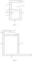
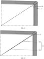
- a specific structure is shown in FIG. 1 , and includes: a top support portion 1, a bottom support portion 2, and a transverse edge portion 5; the top support portion 1 and the transverse edge portion 5 enclose a holding slot 10, and the top support portion 1 has a bearing surface 101 facing the holding slot 10, the bottom support portion 2 is arranged opposite to the top support portion 1, and the transverse edge portion 5 is located at one side of the top support portion 1 away from the bottom support portion 2.
- the photovoltaic frame is molded by a carbon steel sheet material after processing.
- the photovoltaic frame further includes: a first side edge portion 3, a second side edge portion 4, and a third side edge portion 7; the top support portion 1, the second side edge portion 4 and the transverse edge portion 5 enclose the above holding slot 10; the first side edge portion 3 connects the top support portion 1 and the bottom support portion 2; the third side edge portion 7 connects the top support portion 1 and the bottom support portion 2; and the third side edge portion 7, the first side edge portion 3, the top support portion 1 and the bottom support portion 2 enclose a closed cavity 20.
- adjacent structures are separated by dotted lines in FIG. 1 , and the dotted lines are not illustrated in subsequent figures.
- the photovoltaic frame is a photovoltaic frame without a C-edge.
- FIG. 2 is another sectional view of the photovoltaic frame of this embodiment.
- the photovoltaic frame further includes a third side edge portion 7.
- the third side edge portion 7 connects the top support portion 1 and the bottom support portion 2, and the third side edge portion 7 is connected with one side edge of the bottom support portion 2.
- a joint between the first side edge portion 3 and the bottom support portion 2 is spaced from the other side edge of the bottom support portion 2.
- the photovoltaic frame shown in FIG. 2 is a photovoltaic frame with a C-edge (as shown in FIG. 2 , the length of the bottom support portion 2 is greater than the length of the top support portion 1)
- the photovoltaic frame shown in FIG. 1 is a photovoltaic frame without a C-edge.
- the structure of the photovoltaic frame is not specifically limited in this embodiment, and the photovoltaic frames with different structures may be designed according to actual needs, only by ensuring that the photovoltaic frame is molded by the carbon steel sheet material after processing.
- the photovoltaic frame may also be an S-shaped frame, that is, the photovoltaic frame may not need to be provided with the above-described third side edge portion.
- the carbon steel sheet material in this embodiment contains carbon, and a mass fraction of the carbon is in a range of 0.04% to 0.25%. Since too low carbon content in the carbon steel sheet material may lead to a weak strength of the carbon steel sheet material, which is difficult to meet the structural strength requirements of the photovoltaic frame. The excessive carbon content in the carbon steel sheet material may lead to an increase in a salt spray corrosion rate of the carbon steel sheet material, which is difficult to meet the requirement of a warranty period of the photovoltaic frame. By using the carbon steel sheet material with this carbon content range to manufacture the photovoltaic frame, the strength of the photovoltaic frame may meet the design requirements without affecting the warranty period of the photovoltaic frame.
- the mass fraction of the carbon content in the carbon steel sheet material in this embodiment is preferably 0.12% or 0.13%. Using the carbon steel sheet material with such a carbon content value to manufacture the photovoltaic frame may make the photovoltaic frame have stronger strength and longer warranty period.
- the carbon steel sheet material may further contain at least one of silicon, manganese, phosphorus or sulfur, and a mass fraction of the silicon is less than or equal to 0.5 %, a mass fraction of the manganese is less than or equal to 0.6%, a mass fraction of the phosphorus is less than or equal to 0.1%, and a mass fraction of the sulfur is less than or equal to 0.045%.
- the carbon steel sheet material has a small amount of sulfur element or phosphorus element, which may enhance the strength and hardness of the carbon steel sheet material, and improve the formability and processing property of the carbon steel sheet material, such as a cold roll forming formability, a bending property or a cutting processing property of the carbon steel sheet material. If the content of the sulfur element or the phosphorus element is too high, a toughness of the carbon steel sheet material may be reduced correspondingly, which easily leads to a problem of brittle fracture. Therefore, the mass fraction of the phosphorus is less than or equal to 0.1%, such as 0.01%, 0.05% and 0.08%; the mass fraction of the sulfur is less than or equal to 0.045%, such as 0.015%, 0.02% and 0.04%.
- the strength and hardness of the carbon steel sheet material are improved, while preventing the toughness of the carbon steel sheet material from being too low.
- Adding a manganese element or a silicon element as a deoxidizer in the process of manufacturing the carbon steel sheet material may reduce an iron oxide into an iron and prevent the carbon steel sheet material from becoming brittle.
- a proper amount of the manganese element or the silicon element may bring a solid solution strengthening effect.
- the solid solution strengthening refers to a phenomenon that the strength and hardness of a pure metal are improved after proper alloying.
- the solid solution strengthening may improve the strength and hardness of the carbon steel sheet material, which makes the property of the carbon steel sheet material better, and is more conductive to improving a cold roll forming or a grooving and bending forming to make a photovoltaic frame with excellent property, thus further avoiding problems such as the fracture in the forming process.
- the mass fraction of the silicon is less than or equal to 0.5%, such as 0.1%, 0.25%, and 0.4%.
- the mass fraction of the manganese is less than or equal to 0.6%, such as 0.01%, 0.4% and 0.5%.
- the aforementioned mass fraction refers to a ratio of a relative atomic mass (need to multiply a coefficient) of each atom in a compound to a total formula weight, that is, a proportion of an element in a certain substance.
- the mass fraction of the carbon refers to a proportion of the carbon element in the carbon steel sheet material.
- the strength of the carbon steel sheet material is in a range of 200 MPa to 600 MPa.
- the strength of the carbon steel sheet material represents a mechanical property of the carbon steel sheet material against fracture and excessive deformation.
- the manufactured photovoltaic frame may meet the design requirements and is not easy to deform under an action of an external force, which improves the stability of the photovoltaic frame.
- the strength of the carbon steel sheet material in this embodiment is preferably 300 MPa or 400 MPa.
- the photovoltaic frame manufactured by the carbon steel sheet material with such strength may make the photovoltaic frame more stable.
- a percentage of breaking elongation of the carbon steel sheet material is within a range of 15% to 36%.
- a ratio of an elongation length after stretching to a length before stretching is the percentage of breaking elongation of the carbon steel sheet material.
- the photovoltaic frame is molded by selecting the carbon steel sheet material after processing. Since the strength of the carbon steel sheet material may reach more than three times the strength of the aluminum material, the structural strength of the photovoltaic frame is enhanced, thereby improving the stability of the photovoltaic frame. In addition, due to the high structural strength of the photovoltaic frame, the present disclosure does not need to set a height of the photovoltaic frame higher to adapt to a large-sized photovoltaic module, thereby effectively reducing the thickness and weight of the photovoltaic frame, improving a production efficiency of the photovoltaic frame and reducing a production cost of the photovoltaic frame.
- a thickness of the carbon steel sheet material in this embodiment is in a range of 0.2 mm to 2 mm.
- the carbon steel sheet material with such a thickness range may reduce the production cost of the photovoltaic frame while ensuring the strength of the photovoltaic frame.
- the thickness of the carbon steel sheet material in this embodiment is preferably 0.6-1mm. Adopting the carbon steel sheet material with such thickness to manufacture the photovoltaic frame may reduce the production cost of the photovoltaic frame as much as possible while ensuring the strength of the photovoltaic frame.
- any one of a thickness of the top support portion 1, a thickness of the bottom support portion 2, a thickness of the first side edge portion 3, a thickness of the second side edge portion 4 and a thickness of the transverse edge portion 5 is a frame thickness, and a ratio of the frame thickness to the thickness of the carbon steel sheet material is in a range of 1 to 4. That is to say, after the photovoltaic frame is molded in this embodiment, the thickness of the frame is not limited to the same everywhere.
- the carbon steel sheet material may be folded and extruded by calendaring, so that the ratio of the thickness of the top support portion 1, the bottom support portion 2, the first side edge portion 3, the second side edge portion 4 and the transverse edge portion 5 to the thickness of the carbon steel sheet material is in the range of 1 to 4.
- the shape and structure of the photovoltaic frame are diversified, which may meet various design requirements. It should be noted that, in practical applications, the specific structure of the photovoltaic frame is not limited to only having the top support portion 1, the bottom support portion 2, the first side edge portion 3, the second side edge portion 4 and the transverse edge portion 5, but may also have other structures.
- the ratio of the frame thickness of the structure to the thickness of the carbon steel sheet material is also in the range of 1 to 4.
- an included angle between any two adjacent ones of the top support portion 1, the bottom support portion 2, the first side edge portion 3, the second side edge portion 4 and the transverse edge portion 5 is in a range of 20-160 degree.
- the photovoltaic frame in this embodiment is molded by the carbon steel sheet material after processing.
- the photovoltaic frame is molded by extruding and stretching the carbon steel sheet material.
- the manufacturing process of the photovoltaic frame is simple, the cost is low, and there is no pollution in the manufacturing process.
- the photovoltaic frame is molded by cold roll forming the carbon steel sheet material.
- the cold roll forming process is to mechanically bend the carbon steel sheet material into a profile with a certain shape and size at room temperature.
- the advantages of the cold roll forming are: it may produce all kinds of extremely thin, extremely wide and complex profiles that may not be produced by rolling; it saves metal materials; the mechanical property of the products is good.
- Commonly used cold roll forming processing methods include a roll bending, a press bending, a drawing bending and a bending.
- a second embodiment of the present disclosure relates to a photovoltaic frame, and this embodiment is further improved on the basis of the first embodiment.
- the specific improvement lies in that the photovoltaic frame in this embodiment further includes a weather-resistant protective layer, which at least covers an outer surface of at least one of a top support portion, a bottom support portion, a first side edge portion, a second side edge portion or a transverse edge portion, so as to further improve the reliability of the photovoltaic frame.
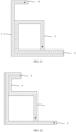
- FIG. 3 is a schematic structural diagram of the photovoltaic frame.
- a weather-resistant protective layer 6 covers the outer surfaces of a top support portion 1, a bottom support portion 2, a first side edge portion 3, a second side edge portion 4 and a transverse edge portion 5.
- the weather-resistant protective layer 6 includes an alloy plating layer or an organic film layer.
- the outer surfaces of the top support portion 1, the bottom support portion 2, the first side edge portion 3, the second side edge portion 4 and the transverse edge portion 5 shown in FIG. 3 are all covered by the weather-resistant protective layer 6.
- the weather-resistant protective layer 6 may only cover the outer surfaces which are in contact with the external environment among the top support portion 1, the bottom support portion 2, the first side edge portion 3, the second side edge portion 4 and the transverse edge portion 5 (for example, it may only cover the top support portion 1, the bottom support portion 2 and the transverse edge portion 5), so as to reduce the production cost of the photovoltaic frame while ensuring that the photovoltaic frame is difficult to be corroded by external water, oxygen or other substances and the service life of the photovoltaic frame is prolonged.
- a position and thickness of the weather-resistant protective layer 6 in this embodiment may be set according to actual requirements, so as to obtain a photovoltaic frame that meets the requirements.
- the photovoltaic frames shown in FIGs. 4-7 are specifically described below.
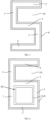
- FIG. 4 is a sectional view of a photovoltaic frame in a feasible embodiment.
- the photovoltaic frame further includes a third side edge portion 7, which connects the top support portion 1 and the bottom support portion 2.
- the third side edge portion 7, the first side edge portion 3, the top support portion 1 and the bottom support portion 2 enclose a closed cavity 20.
- the weather-resistant protective layer 6 further covers an inner wall surface of the closed cavity 20.
- the closed cavity 20 is also in contact with the external environment.
- the inner wall surface of the closed cavity 20 may not be corroded by external water, oxygen or other substances, thus further prolonging a service life of the photovoltaic frame.
- the weather-resistant protective layer 6 covers all the inner wall surfaces 201 of the closed cavity 20. However, in practical applications, the weather-resistant protective layer 6 may only cover some inner wall surfaces 201 of the closed cavity 20.
- the specific structure is shown in FIG. 5 .
- the inner wall surface 201 includes: a first surface 201A, which is a surface of the first side edge portion 3 facing the third side edge portion 7; a second surface 201B, which is a surface of the third side edge portion 7 facing the first side edge portion 3; a third surface 201C, which is a surface of the top support portion 1 facing the bottom support portion 2; and a fourth surface 201D , which is a surface of the bottom support portion 2 facing the top support portion 1.
- the weather-resistant protective layer 6 covers only the first surface 201A and the second surface 201B.
- a surface area of the first surface 201A and the second surface 201B of the photovoltaic frame is larger than that of the third surface 201C and the fourth surface 201D, resulting in that the first surface 201A and the second surface 201B have a larger contact surface with the external environment, and are more vulnerable to be corroded by external water, oxygen or other substances.
- the weather resistant protective layer 6 is set to only cover the first side 201A and the second side 201B, so that the production cost of the photovoltaic frame is reduced while ensuring that the inner wall surface 201 is difficult to be corroded by external water, oxygen or other substances, and the service life of the photovoltaic frame is prolonged.
- the weather-resistant protective layer 6 includes a first weather-resistant protective layer 61 covering an outer surface of the top support portion 1, the bottom support portion 2, the first side edge portion 3, the second side edge portion 4 or the transverse edge portion 5; a second weather-resistant protective layer 62 covering the inner wall surface 201 of the closed cavity 20, and a thickness of the second weather-resistant protective layer 62 is smaller than a thickness of the first weather-resistant protective layer 61.
- the outer surface of the photovoltaic frame is more easily to be corroded by external water, oxygen or other substances, and the thicker the weather-resistant protective layer 6 is, the stronger its protection ability will be, but the production cost of the weather-resistant protective layer 6 may be higher. Therefore, an arrangement with such structure may ensure that the outer surface and the inner wall surface 201 of the photovoltaic frame are not corroded by external water, oxygen or other substances, while further reducing the production cost of the photovoltaic frame.
- the outer surfaces of the top support portion 1, the bottom support portion 2, the first side edge portion 3, the second side edge portion 4 and the transverse edge portion 5 shown in FIG. 6 are all covered by the weather-resistant protective layer 6.
- the weather-resistant protective layer 6 may only cover the outer surfaces which are in contact with the external environment among the top support portion 1, the bottom support portion 2, the first side edge portion 3, the second side edge portion 4 and the transverse edge portion 5.
- the weather-resistant protective layer 6 shown in FIG. 6 also covers all the inner wall surfaces 201 of the closed cavity 20, but in practical applications, the weather-resistant protective layer 6 may only cover some inner wall surfaces 201 of the closed cavity 20.
- a grammage of the first weather-resistant protective layer 61 in this embodiment is in a range of 20g/m 2 to 500g/m 2 .
- the production cost of the first weather-resistant protective layer 61 may be effectively controlled while ensuring that the first weather-resistant protective layer 61 may isolate the external water, oxygen or other substances, and the property of the photovoltaic frame may not be affected due to the excessive thickness of the first weather-resistant protective layer 61.
- the grammage of the first weather-resistant protective layer 61 is 260g/m 2 or 900 g/m 2 .
- the first weather-resistant protective layer 61 in this grammage range may ensure that the first weather-resistant protective layer 61 isolates the external water, oxygen or other substances while reducing the production cost of the first weather-resistant protective layer 61 as much as possible.
- a grammage of the second weather-resistant protective layer 62 is in a range of 0g/m 2 to 500g/m 2 .
- the production cost of the second weather-resistant protective layer 62 may be effectively controlled while ensuring that the second weather-resistant protective layer 62 may isolate the external water, oxygen or other substances.
- the grammage of the second weather-resistant protective layer 62 is 240g/m 2 or 250g/m 2 .
- the second weather-resistant protective layer 62 in this grammage range may ensure that the second weather-resistant protective layer 62 isolates the external water, oxygen or other substances while reducing the production cost of the second weather-resistant protective layer 62 as much as possible, without making the thickness of the second weather-resistant protective layer 62 exceed the thickness of the first weather-resistant protective layer 61.
- the second side edge portion 4 includes a first inner surface 41 and a first outer surface 42 which are opposite to each other, and the first inner surface 41 is an inner wall of the holding slot 10.
- the transverse edge portion 5 includes a second inner surface 51 and a second outer surface 52 which are opposite to each other, and the second inner surface 51 faces the top support portion 1.
- the top support portion 1 includes a third inner surface 11 and a third outer surface 12 which are opposite to each other, and the third inner surface 11 faces the transverse edge portion 5.
- the weather-resistant protective layer 6 includes a first protective layer 601 covering the first inner surface 41, the second inner surface 51 and the third inner surface 11; a second protective layer 602 covering the first outer surface 42, the second outer surface 52 and the third outer surface 12, and a thickness of the second protective layer 602 is greater than a thickness of the first protective layer 601. Since the holding slot 10 is usually used to hold a photovoltaic module, that is, the inner wall of the holding slot 10 may contact with the photovoltaic module, which may cause the second protective layer 602 provided on the inner wall of the holding slot 10 to be worn, thus causing the function of the second protective layer 602 to be affected.
- the second protective layer 602 may still play its due protective function (i.e., isolate the external water, oxygen or other substances from contacting the inner wall of the holding slot 10) even if it is worn after contacting with the photovoltaic modules, thereby further improving the reliability of the photovoltaic frame.
- the weather-resistant protective layer 6 is an alloy plating layer, and the material of the alloy plating layer includes any one or more of galvanization, galvanized aluminum or galvanized magnesium aluminum.
- the weather-resistant protective layer 6 of this embodiment may also be an organic film layer, and the material of the organic film layer includes any one or more of polyethylene, polyvinylidene fluoride, polyurethane, polyvinyl chloride or silane-modified polymer.
- a third embodiment of the present disclosure relates to a photovoltaic frame, and this embodiment is further improved on the basis of the first embodiment.
- the specific improvement lies in that the photovoltaic frame further has a closed cavity 20, and the closed cavity 20 is filled with a foaming layer 20A to further improve the stability of the photovoltaic frame.
- the photovoltaic frame includes a third side edge portion 7, which connects a top support portion 1 and a bottom support portion 2, and the third side edge portion 7, a first side edge portion 3, the top support portion 1 and the bottom support portion 2 enclose the closed cavity 20; the foaming layer 20A is filled in the closed cavity 20.
- the foaming layer 20A with a high strength and a good adhesion is arranged in the closed cavity 20, so that the foaming layer 20A and the photovoltaic frame made of a carbon steel bear a force together, thereby further enhancing a yield strength of the photovoltaic frame.
- the material of the foaming layer 20A is an organic foaming material or an inorganic foaming material, preferably made of a rigid polyurethane foaming plastic or an unsaturated polyester plastic.
- the unsaturated polyester plastic includes a component A and a component B, where the component A includes an unsaturated polyester resin, a thickener, an initiator and a filler, and the component B is a glass fiber coarse sand or a glass fiber mat.
- the polyurethane foaming plastic in the present disclosure referred to as a rigid polyurethane foam for short, has excellent properties such as a light weight, a high strength, a good dimensional stability, a strong adhesive force, and has a good adhesive strength to metals such as steel, aluminum and stainless steel, and most plastic materials such as wood, concrete and asphalt, etc.
- a closed cell rate of the rigid polyurethane is more than 95%, which belongs to a hydrophobic material
- the photovoltaic frame in this embodiment has moisture-proof and waterproof properties.
- the polyurethane is a kind of flame-retardant self-extinguishing material after adding a flame retardant, and its softening point may reach above 250°C, so that the photovoltaic frame in this embodiment has properties of fireproof, flame retardant and high-temperature resistance.
- a ratio of a volume of the foaming layer 20A to a volume of the closed cavity 20 shown in FIG. 8 is almost equal to 100%, that is, the foaming layer 20A fills the closed cavity 20.
- the foaming layer 20A may not fill the closed cavity 20, and the ratio of the volume of the foaming layer 20A to the volume of the closed cavity 20 is in a range of 60% to 100%.
- the ratio of the volume of the foaming layer 20A to the volume of the closed cavity 20 is 80% or 85%. With the foaming layer 20A with such a volume ratio in the closed cavity 20, the photovoltaic frame has higher yield strength and lower production cost.
- a fourth embodiment of the present disclosure relates to a photovoltaic frame, and this embodiment is further improved on the basis of the first embodiment.
- the specific improvement lies in that the photovoltaic frame further has a closed cavity 20 and a reinforcing rib 20B.
- the reinforcing rib 20B is located on an inner wall surface of the closed cavity 20 to further improve the stability of the photovoltaic frame.
- the reinforcing rib 20B includes: a first reinforcing rib 20B1 and a second reinforcing ribs 20B2.
- the first reinforcing rib 20B1 connects a first vertex angle and a second vertex angle, where the first vertex angle is an included angle between a first side edge portion 3 and a top support portion 1, and the second vertex angle is an included angle between a third side edge portion 7 and a bottom support portion 2;
- the second reinforcing ribs 20B2 connects a third vertex angle and a fourth vertex angle, where the third vertex angle is an included angle between the first side edge portion 3 and the bottom support portion 2, and the fourth vertex angle is an included angle between the third side edge portion 7 and the bottom support portion 2.
- the number and setting position of the reinforcing rib 20B in this embodiment are not limited to this.
- the positions and numbers of other reinforcing ribs 20B which are arranged in the closed cavity 20 and may increase the strength of the closed cavity 20 may be set according to the actual needs, which are all within the protection scope of the present disclosure.
- a fifth embodiment of the present disclosure relates to a photovoltaic frame, and this embodiment is further improved on the basis of the first embodiment.
- the specific improvement lies in that the photovoltaic frame further has a closed cavity 20 and a protrusion 20C.
- the protrusion 20C is located on an inner wall surface 201 of the closed cavity 20 to further enhance a strength of the photovoltaic frame.
- the protrusion 20C includes: a first protrusion 20C1 and a second protrusion 20C2; the first protrusion 20C1 is provided on a surface of a first side edge portion 3 facing the third side edge portion 7; the second protrusion 20C2 is provided on a surface of a third side edge portion 7 facing the first side edge portion 3.
- the protrusion 20C shown in FIG. 9 is only provided on the surface of the first side edge portion 3 facing the third side edge portion 7, and the surface of the third side edge portion 7 facing the first side edge portion 3.
- the setting position of the protrusion 20C is not limited to this, and may also be provided on all other surfaces of the closed cavity, which is not specifically limited in this embodiment.
- a plurality of the first protrusions 20C1 are arranged at intervals on the surface of the first side edge portion 3 facing the third side edge portion 7; and a plurality of the second protrusions are arranged at intervals on the surface of the third side edge portion 7 facing the first side edge portion 1.
- the first side edge portion 3 and/or the third side edge 7 may be stressed evenly, thus further improving the stability of the photovoltaic frame.
- the number of the first protrusions 20C1 is the same as the number of the second protrusions 20C2.
- a sixth embodiment of the present disclosure relates to a carbon steel sheet material, and this embodiment is a further improvement of the first embodiment.
- the specific improvement lies in that in this embodiment, the carbon steel sheet material includes a plurality of portions to be bent 80, and a photovoltaic frame is molded by bending the portions to be bent 80 of the carbon steel sheet material. In this way, a production efficiency of the photovoltaic frame may be improved and a production process of the photovoltaic frame may be simplified.
- the carbon steel sheet material includes a top surface 81 and a bottom surface 82 which are oppositely arranged.
- the portion to be bent 80 has at least one groove 83 recessed from the top surface 81 toward the bottom surface 82.
- An extending direction of each of the portions to be bent 80 is a first direction, and an extending direction of a top opening of the groove 83 is the same as the first direction.
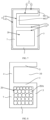
- FIG. 11 is a partial three-dimensional structural diagram of the carbon steel sheet material.
- the material of the carbon steel sheet material is a steel profile.
- the steel profile is a carbon steel, and a hardness of the steel profile varies with a carbon content.
- the carbon steel sheet material includes a plurality of portions to be bent 80. In the process of forming the photovoltaic frame, the carbon steel sheet material is bent along the portions to be bent 80.
- the number of the portions to be bent 80 in the carbon steel sheet material may be set according to a specific structure of the photovoltaic frame, and a distance between adjacent portions to be bent 80 may be set according to a length of each edge of the photovoltaic frame.
- FIG. 12 is a first sectional view of the portion to be bent 80 in FIG. 11 along the first direction.
- the portion to be bent 80 has a groove 83 extending from one end to the other end of the carbon steel sheet material in the first direction. That is, one portion to be bent 80 corresponds to one groove 83, and the groove 83 crosses the carbon steel sheet material, that is, a length of the top opening of the groove 83 is the same as a width of the carbon steel sheet material along the first direction.
- the groove 83 occupies a large space in the portion to be bent 80, so that the carbon steel sheet material is easier to be bent into shape.
- the carbon steel sheet material of a hard material such as the steel profile it is suitable to adopt the groove 83 across both ends of the carbon steel sheet material.
- a bottom of the groove 83 is located in the portion to be bent 80, and a ratio of a depth c of the groove 83 to a thickness f of the carbon steel sheet material between the adjacent portions to be bent 80 is in a range of 0.2-0.6, such as 0.3 or 0.5.
- the ratio is within the range, it may not only ensure that the portion to be bent 80 has a certain strength, avoid a fracture of the carbon steel sheet material, but also ensure that the portion to be bent 80 is easy to bend.
- a single groove 83 across the carbon steel sheet material shall not penetrate through the top surface 81 and the bottom surface 82 of the carbon steel sheet material; otherwise the carbon steel sheet material is no longer integrally formed.
- a thickness e of the portion to be bent 80 directly opposite to the groove 83 is in a range of 1.2-4mm. If the thickness e is too large, it will easily lead to a problem of inability to bend; and if the thickness e is too small, it will easily lead to a problem of breakage.
- the portion to be bent 80 within the above thickness range has both good strength and toughness, which may avoid the above two problems.
- FIG. 13 is a second sectional view of the portion to be bent 80 in FIG. 11 along the first direction.
- the portion to be bent 80 has a groove 83, but the groove 83 does not cross the carbon steel sheet material, that is, there is no opening at both ends of the carbon steel sheet material along the first direction. In this way, the fracture of the carbon steel sheet material caused by an excessive bending angle or an excessive bending force may be avoided.
- FIGs. 14 to 16 are four different sectional views of the upper portion to be bent 80 in FIG. 11 along the first direction.
- the portion to be bent 80 has at least two grooves 83 arranged at intervals, and an arrangement direction of the grooves 83 arranged at intervals is the same as the first direction. Since a plurality of the grooves 83 are arranged adjacent to each other, the carbon steel sheet material between the adjacent grooves 83 still has enough thickness, which may ensure that the portion to be bent 80 has a high strength and prevent the portion to be bent 80 from breaking.
- a length b of the top opening of the groove 83 is smaller than a distance a between the adjacent grooves 83. Since the carbon steel sheet material between the adjacent grooves 83 has high strength, when the distance a between the adjacent grooves 83 is large, the portion to be bent 80 may be ensured to have high strength. Specifically, when a width of the carbon steel sheet material along the first direction is within a range of 20mm-400mm, one groove 83 and the carbon steel sheet material between the grooves 83 serve as one group of a unit structure.
- N groups of the unit structures for one portion to be bent 80 there are N groups of the unit structures for one portion to be bent 80, and (a+b)*N is the same as the width of the carbon steel sheet material along the first direction, where a/b is less than 100% and n is 2-20.
- N may be 2.5 (that is, having two groups of the unit structures and one groove 83 in a group of the unit structure or the carbon steel sheet material between the grooves 83), 5, 10, etc.
- the carbon steel sheet material further includes a first side surface 801 and a second side surface 802 both for connecting the top surface 81 and the bottom surface 82, and the first side surface 801 is opposite to the second side surface 802.
- the groove 83 at least includes: a first groove 831, which penetrates through the first side surface 801; a second groove 832, which penetrates through the second side surface 802. In this way, when the portion to be bent 80 is bent, both ends of the portion to be bent 80 may maintain a good flatness and improve the aesthetics.
- the bottom of the groove 83 is located in the portion to be bent 80, and the ratio of the depth c of the groove 83 to the thickness f of the carbon steel sheet material between the adjacent portions to be bent 80 is in a range of 0.5-1.
- the ratio of the depth c of the grooves 83 arranged at intervals to the thickness f of the carbon steel sheet material between the adjacent portions to be bent 80 is larger.
- the main reason for this design is that the carbon steel sheet material between the grooves 83 arranged at intervals has high strength and is not easy to bend.
- the ratio of the depth of the groove 83 to the thickness f of the carbon steel sheet material between the adjacent portions to be bent 80 is less than 0.5, the whole portion to be bent 80 is difficult to be bent. Therefore, the groove 83 is correspondingly deepened, then the thickness of the portion to be bent 80 corresponding to the groove 83 becomes smaller, which may make the whole portion to be bent 80 be bent more easily.
- Example two referring to FIGs. 11 and 15 , the groove 83 does not penetrate through the first side surface 801 and the second side surface 802.
- Example three referring to FIGs. 11 and 16 , the groove 83 penetrates through the top surface 81 and the bottom surface 82 of the portion to be bent 80. Since the ratio between the depth of the groove 83 and the thickness of the carbon steel sheet material does not need to be considered, the process difficulty is reduced.
- FIG. 17 is a sectional structural diagram of the portion to be bent 80 in FIG. 11 along a direction perpendicular to the first direction.
- a cross section shape of the groove 83 includes an inverted triangle or an inverted trapezoid, and the top opening of the groove 83 is larger than a bottom opening of the groove 83.
- a certain width d is reserved at the bottom of the groove 83, designing a certain width is easy to maintain an original deformation of the carbon steel sheet material, so that the carbon steel sheet material has a certain space for combination during the bending process, which is conducive to fixation and bending.
- the width d of the bottom opening of the groove 83 is in a range of 4-10mm, and the opening in this width range is closest to the deformation of the carbon steel sheet material when bending. If the reserved width d is greater than 10mm, an excessive gap may be left between the opposite side walls of the groove 83 after the portion to be bent 80 is bent.
- an included angle between the opposite side walls of the groove 83 is in a range of 20 degrees to 160 degrees.
- photovoltaic frames with different shapes may be manufactured, such as parallelogram, triangle, diamond and other irregular shapes.
- the photovoltaic frames with various shapes may be applied to different application scenarios.
- the photovoltaic frames in the shape of parallelogram, triangle or diamond may be applied to building integrated photovoltaic (BIPV).
- BIPV building integrated photovoltaic
- a difference in the lengths of the opposite side edges of the groove 83 is in a range of 0-15mm. That is, the lengths of the opposite side edges may be different. For example, a length of one side edge is within a cavity of the long side edge and a length of the other side edge is within a cavity of the short side edge. Since the carbon steel sheet material should be fixed in a certain way after bending and molding, such as welding or riveting, if the length difference between the opposite side edges exceeds a threshold, a firmness of the finally formed photovoltaic frame may be affected, which is not conducive to the fixing and installation of the four edges and is easy to fall apart. The length difference between the opposite side edges being within a threshold range of 15mm may ensure the stability of the finally formed photovoltaic frame.
- the lengths of the opposite side edges of the groove 83 are equal. In this way, it is beneficial to improve the aesthetics of the finally formed photovoltaic frame; and may maintain a uniform stress during installation, packaging and transportation to avoid deformation.
- the carbon steel sheet material provided in this embodiment has the plurality of portions to be bent 80 and the groove 83 on the portion to be bent 80.
- an integrated photovoltaic frame may be formed.
- the number and type of the grooves 83 may be changed according to the size and shape of the photovoltaic frame. In this way, an automation degree of the photovoltaic frame production may be improved, and the production efficiency may be improved.
- a seventh embodiment of the present disclosure provides a photovoltaic frame, and the photovoltaic frame of this embodiment may be made of the carbon steel sheet material of the sixth embodiment.
- FIGs. 18- 25 are schematic structural diagrams of the photovoltaic frame.
- the photovoltaic frame includes: a plurality of connection portions 30 connected in sequence, where the connection portions 30 are used for forming a top support portion 1, a bottom support portion 2, a first side edge portion 3, a second side edge portion 4 and a transverse edge portion 5; the top support portion 1, the second side edge portion 4 and the transverse edge portion 5 enclose a holding slot, and the top support portion 1 has a bearing surface facing the holding slot;
- the bottom support portion 2 is arranged opposite to the top support portion 1;
- the first side edge portion 3, the top support portion 1 and the bottom support portion 2 enclose a closed cavity 20, and the first side edge portion 3 and the second side edge portion 4 are respectively located on opposite sides of the top support portion 1;
- a bending portion 9 which connects two
- FIGs. 21 and 22 are enlarged views of the bending portion of the photovoltaic frame.
- the two abutting side surfaces 90 of the bending portion 9 are attached to each other. At this time, a contact area between the two side surfaces 90 is large, and a firmness of the bending portion 9 is good.
- the two abutting side surfaces 90 of the bending portion 9 include: two contact surfaces 901 which are attached to each other; a connection surface 902 connected with each of the contact surfaces 901, with a gap between the two opposite connection surfaces 902. Accordingly, an adhesive may be filled in the gap to improve the firmness of the bending portion 9.
- the included angles between the connection portions 30 are different. If different portions to be bent 80 are manufactured for different included angles (refer to FIG. 11 ), the process is more complicated and the cost is high. Therefore, the same type of the portions to be bent 80 may be manufactured.
- two side surfaces 90 of some of the bending portions 9 have gaps, and two side surfaces 90 of some of the bending portions 9 are attached to each other. The some of the bending portions 9 having the gaps are filled with the adhesive. In this way, not only the process may be simplified and the cost may be saved, but also the firmness of the photovoltaic frame may be improved.
- FIGs. 18 to 20 are schematic diagrams of three kinds of three-dimensional structures of the photovoltaic frame. Referring to FIGs. 18 to 20 , the top support portion 1, the second side edge portion 4 and the transverse edge portion 5 enclose the holding slot for placing a photovoltaic panel, and the bearing surface of the top support portion 1 supports the photovoltaic panel.
- the first side edge portion 3, the top support portion 1 and the bottom support portion 2 enclose the closed cavity 20, and the closed cavity 20 is an open cavity.
- the bending portion 9 is arranged between any two adjacent connection portions 30.
- the photovoltaic frame with the open cavity has a simple structure and low cost.
- connection portions 30 is a single-layer sheet material structure, which may simplify the process, save materials and reduce the cost.
- connection portion 30 further includes: a third side edge portion 7, which connects the top support portion 1 and the bottom support portion 2 to enclose an enclosed closed cavity 20, and the bending portion 9 is also arranged between the third side edge portion 7 and the top support portion 1 and/or between the first side edge portion 3 and the bottom support portion 2.
- the enclosed closed cavity 20 may protect a filling inside the enclosed closed cavity 20 to enhance the strength of the photovoltaic frame.
- the third side edge portion 7 also has a supporting function, and the photovoltaic frame is not easily deformed.
- the top support portion 1 is a single layer structure. Therefore, consumables are fewer and the structure is simple.
- the top support portion 1 is divided into a first part and a second part.
- the first part corresponds to the closed cavity 20, and the first part is a single-layer sheet material structure.
- the second part is outside the closed cavity 20, and the second part is a double-layer sheet material structure. Therefore, a contact area between the top support portion 1 and the photovoltaic panel is larger and the stability is better.
- the photovoltaic frame may have various shapes, such as parallelogram, triangle, diamond and other irregular shapes.
- the photovoltaic frame with various shapes may be applied to buildings, which may increase the aesthetics.
- At least two adjacent connection portions 30 have an overlapping part, and the overlapping part is a double-layer sheet material structure. Since the photovoltaic frame is integrally formed, for the photovoltaic frame with a complex configuration, the overlapping method may be used to avoid cutting the sheet material into two pieces, thus reducing the process steps. In addition, the double-layer sheet material structure may also enhance the strength of photovoltaic frame.
- One of the top support portion 1, the bottom support portion 2, the first side edge portion 3, the second side edge portion 4, or the transverse edge portion 5 is formed by abutting two connection portions 30 at the head and tail. That is, an enclosed area of the photovoltaic frame is formed by abutting the two connection portions 30. In this way, a firmness of the enclosed area may be ensured, and the deformation of the photovoltaic frame may be avoided.
- the photovoltaic frame is not easily deformed by selecting the connection portion 30 with a weak bearing function such as the top support portion 1, the second side edge portion 4 or the transverse edge portion 5 as the enclosed area.
- FIG. 23 is a first side view of the photovoltaic frame.
- a start point of bending is on the first side edge portion 3, and an ending point is on the transverse edge portion 5; or, the start point of the bending is on the transverse edge portion 5 and the ending point is on the first side edge portion 3.
- connection portion 30 (refer to FIGs. 18-20 ) corresponding to two dotted lines is the double-layer sheet material structure, and the connection portion 30 corresponding to one dotted line is the single-layer sheet material structure.
- the third side edge portion 7 and the bottom support portion 2 are the double-layer sheet material structure, and the photovoltaic frame has high strength.
- the whole photovoltaic frame is integrally formed by a sheet material, so that the manufacturing time may be shortened and the process difficulty may be reduced.
- FIG. 24 is a second side view of the photovoltaic frame.
- the configuration of the photovoltaic frame in FIG. 24 is the same as the configuration of the photovoltaic frame in FIG. 23 , except that a folding order and the number of layers of the connection portion 30 (refer to FIGs. 18-20 ) are different.
- Example two the start point of bending is on the first side edge portion 3, and the end point is on the bottom support portion 2; or the start point of bending is on the bottom support portion 2 and the end point is on the first side edge portion 3.
- the second side edge portion 4 and the transverse edge portion 5 are the double-layer sheet material structure. Since the lengths of the second side edge portion 4 and the transverse edge portion 5 are short, even if the second side edge portion 4 and the transverse edge portion 5 are the double-layer sheet material structure, the photovoltaic frame consumes less sheet material.
- FIG. 25 is the third side view of the photovoltaic frame.
- the connection portion 30 further includes a first connection portion 301 and a second connection portion 302 respectively connected with the third side edge portion 7; and the first connection portion 301, the third side edge portion 7 and the second connection portion 302 enclose a pressing block area, and the bending portion 9 is also arranged between the first connection portion 301 and the third side edge portion 7 and/or between the second connection portion 302 and the third side edge portion 7.
- the pressing block area may be used for fixing the photovoltaic frame to prevent the photovoltaic frame from collapsing.
- the first connection portion 301 and the second connection portion 302 have a double-layer sheet material structure. Since the first connection portion 301 and the second connection portion 302 have a function of fixing the photovoltaic frame, the first connection portion 301 and the second connection portion 302 adopt the double-layer sheet material structure to be firmer and prevent the photovoltaic frame from collapsing.
- the start point of the bending is located at the bottom support portion 2, and the end point of the bending is located at the first side edge portion 3; or the start point of the bending is located at the first side edge portion 3, and the end point of the bending is located at the bottom support portion 2.
- the transverse edge portion 5 and the second side edge portion 4 also have a double-layer sheet material structure.
- the specific structure of the photovoltaic frame provided in this embodiment is not limited to the several examples provided above, and that the photovoltaic frame formed by bending the sheet material body along the portion to be bent is within the scope of this embodiment.
- the photovoltaic frame further includes a reinforcing member (not shown), and the reinforcing member penetrates through the two abutting side surfaces of the bending portion 9.
- the reinforcing member includes a welding reinforcing member, a riveting reinforcing member or a mortise and tenon reinforcing member.
- the reinforcing member may strengthen the firmness of the bending portion 9 and avoid the deformation of the photovoltaic frame.
- the photovoltaic frame provided in this embodiment has the connection portions 30 connected in sequence and the bending portions 9 connecting the adjacent connection portions 30, and the connection portions 30 and the bending portions 9 are integrally formed, so that the production efficiency of the photovoltaic frame may be improved and the production cost may be reduced.
- the overall strength and firmness of the photovoltaic frame may be improved by arranging some of the connection portions 30 with the double-layer structure, reinforcing the bending portion 9 and filling the closed cavity 20.
- An eighth embodiment of the present disclosure provides a method for manufacturing a photovoltaic frame, and the specific process as shown in FIG. 26 includes: In S801, a carbon steel sheet material is provided.
- a carbon content in the carbon steel sheet material in this embodiment is in a range of 0.04% to 0.25%. Since too low carbon content in the carbon steel sheet material may lead to a weak strength of the carbon steel sheet material, which is difficult to meet the structural strength requirements of the photovoltaic frame. The excessive carbon content in the carbon steel sheet material may lead to an increase in a salt spray corrosion rate of the carbon steel sheet material, which is difficult to meet the requirement of a warranty period of the photovoltaic frame. By using the carbon steel sheet material with this carbon content range to manufacture the photovoltaic frame, the strength of the photovoltaic frame may meet the design requirements without affecting the warranty period of the photovoltaic frame.
- the strength of the carbon steel sheet material is in a range of 200 MPa to 600 MPa.
- the strength of the carbon steel sheet material represents a mechanical property of the carbon steel sheet material against fracture and excessive deformation.
- a percentage of breaking elongation of the carbon steel sheet material is within a range of 15% to 36%.
- a ratio of an elongation length after stretching to a length before stretching is the percentage of breaking elongation of the carbon steel sheet material.
- the photovoltaic frame is formed by processing and molding the carbon steel sheet material.
- the photovoltaic frame includes: a top support portion, a bottom support portion, a first side edge portion, a second side edge portion and a transverse edge portion, where the top support portion, the second side edge portion, and the transverse edge portion enclose a holding slot, and the top support portion has a bearing surface facing the holding slot, the bottom support portion is arranged opposite to the top support portion, and the transverse edge portion is located one side of the top support portion away from the bottom support portion; the first side edge portion connects the top support portion and the bottom support portion.
- the photovoltaic frame in this embodiment is not limited to the above-mentioned structure, but may also include other structures, which have been described in detail in the foregoing embodiments, and are not be described here to avoid repetition.
- the carbon steel sheet material is molded after processing. Specifically, a calendaring and cold roll forming process is adopted for the carbon steel sheet material to form the photovoltaic frame. In this way, the method for manufacturing the photovoltaic frame is simple, the cost is low, and there is no pollution in the manufacturing process.
- the carbon steel sheet material of this embodiment includes a plurality of portions to be bent.
- the carbon steel sheet material includes a top surface and a bottom surface which are oppositely arranged.
- the portions to be bent have at least one groove recessed from the top surface toward the bottom surface.
- An extending direction of each of the portions to be bent is a first direction, and an extending direction of a top opening of the groove is the same as the first direction.
- the processing includes: bending the portion to be bent to form the photovoltaic frame. Through an arrangement of this structure, the carbon steel sheet material is easier to bend, thus reducing the difficulty of manufacturing the photovoltaic frame.
- FIG. 27 is a schematic structural diagram corresponding to each step of the manufacturing method.
- the sheet material of the first embodiment is provided.
- the method for manufacturing the sheet material includes: designing the number of the portions to be bent required by a sheet material body and a distance between adjacent portions to be bent according to a required layout of the photovoltaic frame. Further, the shape and number of grooves on the portion to be bent are designed.
- the sheet material body is cut by laser to form the portion to be bent and the groove on the portion to be bent. After forming the portion to be bent, the sheet material is cut off according to a required assembly size. In this way, the sheet material in the first embodiment may be manufactured.
- the remaining sheet material body may still form another photovoltaic frame in succession.
- connection portions and bending portions connected in sequence are formed by bending along the portions to be bent on the sheet material.
- the bending portion connects two adjacent connection portions, and the bending portion includes two abutting side surfaces.
- the plurality of the connection portions and bending portions connected in sequence are integrally formed.
- the bending mode may be a stamping.
- the portion to be bent may also be heated to improve a toughness of the portion to be bent.
- the bending portion is reinforced, such as by welding (resistance welding and argon arc welding may be selected), riveting, mortise and tenon, and other connection assembly scheme, so as to avoid the photovoltaic frame loosing.
- a cavity may also be filled with an organic material such as a polyurethane foam and extruded to enhance the strength of the sheet material.
- a polyurethane foaming temperature should be met in this step. When the temperature is low, an ambient temperature may be raised by means of illumination, hot plate heating, etc., so that the polyurethane meets the foaming requirements.
- the method for manufacturing the photovoltaic frame provided in this embodiment adopts an integrated cutting method, and the cut sheet material is bent to form the photovoltaic frame. Therefore, it is beneficial to improve productivity efficiency and realize a full automation of photovoltaic frame production.
- an embodiment of the present disclosure further provides a photovoltaic module, which includes a stacked structure and the photovoltaic frame provided in any of the above embodiments, where the stacked structure includes a panel, a first adhesive film, a cell piece, a second adhesive film and a backplane which are sequentially stacked.
- a bearing surface of the photovoltaic frame bears the stacked structure.
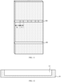
- FIG. 28 is a schematic diagram of a partial three-dimensional structure of the photovoltaic module.
- the photovoltaic module includes a photovoltaic frame 102 and a stacked structure 101.
- a holding slot 10 of the photovoltaic frame 102 holds the stacked structure 101, so that the stacked structure 101 is stably fixed with the photovoltaic frame 102, thereby improving the stability of the photovoltaic module.
- the photovoltaic module may further include a filling portion 10 for filling a gap area between the stacked structure 101 and the holding slot 10.
- the filling portion 10 may also fill other areas of the photovoltaic frame, which may further improve the stability of the photovoltaic frame.
- FIG. 29 is a sectional structural diagram of the stacked structure in FIG. 28 .
- the stacked structure 101 includes a panel 101A, a first adhesive film 101B, a cell piece 101C, a second adhesive film 101D and a backplane 101E which are stacked in sequence, where the panel 101A is located on a light receiving surface of the cell piece 101C, and adjacent cell pieces 101 are overlapped.
- the backplane 101E may be a glass or an organic backplane.
- FIG. 30 is another sectional structural diagram of the stacked structure in FIG. 28 .
- the adjacent cell pieces 101C are not overlapped and an electrical connection may be realized by a ribbon 101F.
- the stacked structure 101 may be a single glass assembly, that is, the panel 101A is the glass, and the backplane 101E may be an organic backplane or a non-transparent backplane.
- the stacked structure 101 may also be a double glass assembly, that is, both the panel 101A and the back panel 101E are the glass.
- the panel 101A includes a long side edge and a short side edge adjacent to each other, where a length of the long side edge is greater than or equal to 2m, and a length of the short side edge is greater than or equal to 1m.
- the stacked structure 101 may be defined as a large-size assembly.
- the photovoltaic frame provided in the foregoing embodiments is combined with the stacked structure 101 to form the photovoltaic assembly, so that when the photovoltaic assembly has the backplane or panel with a poor structural strength, the photovoltaic frame may play a good supporting role, avoiding the backplane or the panel being damaged under the external force, thereby improving the reliability of the photovoltaic assembly.
Landscapes
- Photovoltaic Devices (AREA)
Description
- The embodiments of the present disclosure relate to the field of photovoltaic module technology, in particular to a frame for a photovoltaic module ("photovoltaic frame" hereafter for short), a photovoltaic module and a method for manufacturing the photovoltaic frame.
- Generally, a frame is installed around the photovoltaic module, an edge of a solar cell laminate is accommodated in a notch of the frame, and the photovoltaic module is installed on a bracket through the frame. The frame of the photovoltaic module plays a role in enhancing the strength of the module and sealing the edge of the module.
- At present, in order to adapt to the development of photovoltaic modules, various photovoltaic frames have appeared. However, the existing production process of photovoltaic frame is complicated and costly, and the quality of the photovoltaic frame needs to be improved. Therefore, how to improve the quality of the photovoltaic frame while meeting the requirements of the shape and structure of the finished product without adding too many process steps has become an urgent problem to be solved in the design and manufacturing process of photovoltaic solar modules.
-
CN 208272919U discloses a frame structure for a photovoltaic cell module and a photovoltaic cell module. - The present invention is set out in the appended set of claims.
- Compared with related technologies, the technical solution provided by the embodiment of the present disclosure has the following advantages.
- The photovoltaic frame is molded by selecting the carbon steel sheet material after processing. Since the strength of the carbon steel sheet material may reach more than three times the strength of the aluminum material, the structural strength of the photovoltaic frame is enhanced, thereby improving the stability of the photovoltaic frame. In addition, due to the high structural strength of the photovoltaic frame, the present disclosure does not need to set a height of the photovoltaic frame higher to adapt to a large-sized photovoltaic module, thereby effectively reducing the thickness and weight of the photovoltaic frame, improving a production efficiency of the photovoltaic frame and reducing a production cost of the photovoltaic frame.
- One or more embodiments are described as examples with reference to the corresponding figures in the accompanying drawings, and the examples do not constitute a limitation to the embodiments. Elements with the same reference numerals in the accompanying drawings represent similar elements. The figures in the accompanying drawings do not constitute a proportion limitation unless otherwise stated.
-
FIG. 1 is a sectional view of a photovoltaic frame provided according to a first embodiment not part of the invention; -
FIG. 2 is another sectional view of the photovoltaic frame provided according to the first embodiment of the present disclosure; -
FIG. 3 is a sectional view of a photovoltaic frame provided with a structure not part of the invention and according to a second embodiment of the present disclosure; -
FIG. 4 is a sectional view of a photovoltaic frame with another structure not part of the invention and provided according to the second embodiment of the present disclosure; -
FIG. 5 is a sectional view of a photovoltaic frame with another structure not part of the invention and provided according to the second embodiment of the present disclosure; -
FIG. 6 is a sectional view of a photovoltaic frame with another structure provided according to the second embodiment of the present disclosure; -
FIG. 7 is a sectional view of a photovoltaic frame with another structure not part of the invention and provided according to the second embodiment of the present disclosure; -
FIG. 8 is a sectional view of a photovoltaic frame provided according to a third embodiment of the present disclosure; -
FIG. 9 is a sectional view of a photovoltaic frame provided according to a fourth embodiment of the present disclosure; -
FIG. 10 is a sectional view of a photovoltaic frame provided according to a fifth embodiment of the present disclosure; -
FIG. 11 is a schematic structural diagram of a plate material provided according to a sixth embodiment of the present disclosure; -
FIG. 12 is a first sectional view of a portion to be bent inFIG. 11 along a first direction; -
FIG. 13 is a second sectional view of the portion to be bent inFIG. 11 along the first direction; -
FIG. 14 is a third sectional view of the portion to be bent inFIG. 11 along the first direction; -
FIG. 15 is a fourth sectional view of the portion to be bent inFIG. 11 along the first direction; -
FIG. 16 is a fifth sectional view of the portion to be bent inFIG. 11 along the first direction; -
FIG. 17 is a sectional view of the portion to be bent inFIG. 11 along a direction perpendicular to the first direction; -
FIG. 18 is a structural schematic diagram of a first photovoltaic frame provided by a seventh embodiment not part of the invention; -
FIG. 19 is a schematic structural diagram of a second photovoltaic frame provided by the seventh embodiment; -
FIG. 20 is a schematic structural diagram of a third photovoltaic frame provided by the seventh embodiment; -
FIG. 21 is a first enlarged view of a bending portion of the photovoltaic frame provided by the seventh embodiment; -
FIG. 22 is a second enlarged view of the bending portion of the photovoltaic frame provided by the seventh embodiment; -
FIG. 23 is a first side view of the photovoltaic frame provided by the seventh embodiment; -
FIG. 24 is a second side view of the photovoltaic frame provided by the seventh embodiment; -
FIG. 25 is a third side view of the photovoltaic frame provided by the seventh embodiment; -
FIG. 26 is a flowchart of a method for manufacturing a photovoltaic frame provided by an eighth embodiment not part of the invention; -
FIG. 27 is a schematic structural diagram corresponding to each step of the method for manufacturing the photovoltaic frame provided by the eighth embodiment; -
FIG. 28 is a schematic diagram of a partial three-dimensional structure of a photovoltaic module provided by an embodiment of the present disclosure; -
FIG. 29 is a sectional structural diagram of a stacked structure inFIG. 28 ; -
FIG. 30 is another sectional structural diagram of the stacked structure inFIG. 28 . - According to the background technology, the production efficiency of a photovoltaic frame is low and the cost is high.
- Through an analysis, it is found that the main reasons include: the strength of the existing aluminum frame is limited. Throughout the development history of photovoltaic modules, the size of the photovoltaic module has changed from 250*175*25 mm to the current 1950*995*45 mm. That is to say, the size of the photovoltaic module is constantly increasing, and will develop towards larger size in the future. However, with the increasing size of the photovoltaic module, the size of an aluminum photovoltaic module frame is developing towards the direction of a larger frame section and thicker thickness. The essential reason for this phenomenon is the low strength of the aluminum material itself. When the module size is increased, using an aluminum alloy material to make a section steel, the frame section of the module needs to be reinforced by a structure with larger section and thicker thickness, which may increase the use cost.
- To solve the above problems, the present disclosure provides a photovoltaic frame, a photovoltaic module and a method for manufacturing the photovoltaic frame. The photovoltaic frame in an embodiment of the present disclosure is molded by a carbon steel sheet material after processing. The photovoltaic frame manufactured from the above sheet material can improve a production efficiency of the photovoltaic frame and reduce a production cost, while improving the stability of the photovoltaic frame, which facilitates the production and supply of a whole industrial chain.
- The embodiments of the present disclosure will be described in detail below with reference to the accompanying drawings in order to make the objectives, technical solutions and advantages of the present disclosure clearer. However, it will be apparent to those skilled in the art that, in the various embodiments of the present disclosure, numerous technical details are set forth in order to provide the reader with a better understanding of the present disclosure. However, the technical solutions claimed in the present disclosure may be implemented without these technical details and various changes and modifications based on the following embodiments.
- A first embodiment of the present disclosure relates to a photovoltaic frame. A specific structure is shown in
FIG. 1 , and includes: atop support portion 1, abottom support portion 2, and atransverse edge portion 5; thetop support portion 1 and thetransverse edge portion 5 enclose aholding slot 10, and thetop support portion 1 has abearing surface 101 facing theholding slot 10, thebottom support portion 2 is arranged opposite to thetop support portion 1, and thetransverse edge portion 5 is located at one side of thetop support portion 1 away from thebottom support portion 2. The photovoltaic frame is molded by a carbon steel sheet material after processing. - Specifically, as shown in
FIG. 1 , the photovoltaic frame further includes: a firstside edge portion 3, a secondside edge portion 4, and a thirdside edge portion 7; thetop support portion 1, the secondside edge portion 4 and thetransverse edge portion 5 enclose theabove holding slot 10; the firstside edge portion 3 connects thetop support portion 1 and thebottom support portion 2; the thirdside edge portion 7 connects thetop support portion 1 and thebottom support portion 2; and the thirdside edge portion 7, the firstside edge portion 3, thetop support portion 1 and thebottom support portion 2 enclose aclosed cavity 20. For convenience of marking and distinguishing, adjacent structures are separated by dotted lines inFIG. 1 , and the dotted lines are not illustrated in subsequent figures. - As shown in
FIG. 1 , thebottom support portion 2 and thetop support portion 1 have the same length. The photovoltaic frame is a photovoltaic frame without a C-edge. - Please refer to
FIG. 2 , which is another sectional view of the photovoltaic frame of this embodiment. The photovoltaic frame further includes a thirdside edge portion 7. The thirdside edge portion 7 connects thetop support portion 1 and thebottom support portion 2, and the thirdside edge portion 7 is connected with one side edge of thebottom support portion 2. A joint between the firstside edge portion 3 and thebottom support portion 2 is spaced from the other side edge of thebottom support portion 2. Specifically, the photovoltaic frame shown inFIG. 2 is a photovoltaic frame with a C-edge (as shown inFIG. 2 , the length of thebottom support portion 2 is greater than the length of the top support portion 1), and the photovoltaic frame shown inFIG. 1 is a photovoltaic frame without a C-edge. The structure of the photovoltaic frame is not specifically limited in this embodiment, and the photovoltaic frames with different structures may be designed according to actual needs, only by ensuring that the photovoltaic frame is molded by the carbon steel sheet material after processing. - It should be noted that, in other embodiments, the photovoltaic frame may also be an S-shaped frame, that is, the photovoltaic frame may not need to be provided with the above-described third side edge portion.
- It is worth mentioning that the carbon steel sheet material in this embodiment contains carbon, and a mass fraction of the carbon is in a range of 0.04% to 0.25%. Since too low carbon content in the carbon steel sheet material may lead to a weak strength of the carbon steel sheet material, which is difficult to meet the structural strength requirements of the photovoltaic frame. The excessive carbon content in the carbon steel sheet material may lead to an increase in a salt spray corrosion rate of the carbon steel sheet material, which is difficult to meet the requirement of a warranty period of the photovoltaic frame. By using the carbon steel sheet material with this carbon content range to manufacture the photovoltaic frame, the strength of the photovoltaic frame may meet the design requirements without affecting the warranty period of the photovoltaic frame. The mass fraction of the carbon content in the carbon steel sheet material in this embodiment is preferably 0.12% or 0.13%. Using the carbon steel sheet material with such a carbon content value to manufacture the photovoltaic frame may make the photovoltaic frame have stronger strength and longer warranty period.
- In addition, the carbon steel sheet material may further contain at least one of silicon, manganese, phosphorus or sulfur, and a mass fraction of the silicon is less than or equal to 0.5 %, a mass fraction of the manganese is less than or equal to 0.6%, a mass fraction of the phosphorus is less than or equal to 0.1%, and a mass fraction of the sulfur is less than or equal to 0.045%.
- Specifically, the carbon steel sheet material has a small amount of sulfur element or phosphorus element, which may enhance the strength and hardness of the carbon steel sheet material, and improve the formability and processing property of the carbon steel sheet material, such as a cold roll forming formability, a bending property or a cutting processing property of the carbon steel sheet material. If the content of the sulfur element or the phosphorus element is too high, a toughness of the carbon steel sheet material may be reduced correspondingly, which easily leads to a problem of brittle fracture. Therefore, the mass fraction of the phosphorus is less than or equal to 0.1%, such as 0.01%, 0.05% and 0.08%; the mass fraction of the sulfur is less than or equal to 0.045%, such as 0.015%, 0.02% and 0.04%. By doping the phosphorus or the sulfur with the above content, the strength and hardness of the carbon steel sheet material are improved, while preventing the toughness of the carbon steel sheet material from being too low. Adding a manganese element or a silicon element as a deoxidizer in the process of manufacturing the carbon steel sheet material may reduce an iron oxide into an iron and prevent the carbon steel sheet material from becoming brittle. In addition, a proper amount of the manganese element or the silicon element may bring a solid solution strengthening effect. The solid solution strengthening refers to a phenomenon that the strength and hardness of a pure metal are improved after proper alloying. The solid solution strengthening may improve the strength and hardness of the carbon steel sheet material, which makes the property of the carbon steel sheet material better, and is more conductive to improving a cold roll forming or a grooving and bending forming to make a photovoltaic frame with excellent property, thus further avoiding problems such as the fracture in the forming process. If the content of the manganese element or the silicon element is too high, a corrosion resistance and a welding property of the carbon steel sheet material may be weakened. Therefore, in this embodiment, the mass fraction of the silicon is less than or equal to 0.5%, such as 0.1%, 0.25%, and 0.4%. The mass fraction of the manganese is less than or equal to 0.6%, such as 0.01%, 0.4% and 0.5%. By doping the silicon or the manganese with the above content, in addition to ensuring that the carbon steel sheet material has good strength and hardness characteristics, the carbon steel sheet material also has good corrosion resistance and welding property.
- It should be noted that the aforementioned mass fraction refers to a ratio of a relative atomic mass (need to multiply a coefficient) of each atom in a compound to a total formula weight, that is, a proportion of an element in a certain substance. For example, the mass fraction of the carbon refers to a proportion of the carbon element in the carbon steel sheet material.
- Preferably, the strength of the carbon steel sheet material is in a range of 200 MPa to 600 MPa. The strength of the carbon steel sheet material represents a mechanical property of the carbon steel sheet material against fracture and excessive deformation. By adopting the carbon steel sheet material with such strength range, the manufactured photovoltaic frame may meet the design requirements and is not easy to deform under an action of an external force, which improves the stability of the photovoltaic frame. The strength of the carbon steel sheet material in this embodiment is preferably 300 MPa or 400 MPa. The photovoltaic frame manufactured by the carbon steel sheet material with such strength may make the photovoltaic frame more stable.
- More preferably, a percentage of breaking elongation of the carbon steel sheet material is within a range of 15% to 36%. When the carbon steel sheet material is subjected to the external force to break, a ratio of an elongation length after stretching to a length before stretching is the percentage of breaking elongation of the carbon steel sheet material. By adopting the carbon steel sheet material with such percentage of breaking elongation range, the manufactured photovoltaic frame may meet the design requirements, has a certain deformation capability, and does not break after a slight deformation, which improves the stability of the photovoltaic frame. The percentage of breaking elongation of the carbon steel sheet material in this embodiment is preferably 25% or 26%. The photovoltaic frame manufactured by the carbon steel sheet material with such percentage of breaking elongation may make the photovoltaic frame more stable.
- Compared with related technologies, the photovoltaic frame is molded by selecting the carbon steel sheet material after processing. Since the strength of the carbon steel sheet material may reach more than three times the strength of the aluminum material, the structural strength of the photovoltaic frame is enhanced, thereby improving the stability of the photovoltaic frame. In addition, due to the high structural strength of the photovoltaic frame, the present disclosure does not need to set a height of the photovoltaic frame higher to adapt to a large-sized photovoltaic module, thereby effectively reducing the thickness and weight of the photovoltaic frame, improving a production efficiency of the photovoltaic frame and reducing a production cost of the photovoltaic frame.
- It should be noted that a thickness of the carbon steel sheet material in this embodiment is in a range of 0.2 mm to 2 mm. The carbon steel sheet material with such a thickness range may reduce the production cost of the photovoltaic frame while ensuring the strength of the photovoltaic frame. The thickness of the carbon steel sheet material in this embodiment is preferably 0.6-1mm. Adopting the carbon steel sheet material with such thickness to manufacture the photovoltaic frame may reduce the production cost of the photovoltaic frame as much as possible while ensuring the strength of the photovoltaic frame.
- It is worth mentioning that any one of a thickness of the
top support portion 1, a thickness of thebottom support portion 2, a thickness of the firstside edge portion 3, a thickness of the secondside edge portion 4 and a thickness of thetransverse edge portion 5 is a frame thickness, and a ratio of the frame thickness to the thickness of the carbon steel sheet material is in a range of 1 to 4. That is to say, after the photovoltaic frame is molded in this embodiment, the thickness of the frame is not limited to the same everywhere. The carbon steel sheet material may be folded and extruded by calendaring, so that the ratio of the thickness of thetop support portion 1, thebottom support portion 2, the firstside edge portion 3, the secondside edge portion 4 and thetransverse edge portion 5 to the thickness of the carbon steel sheet material is in the range of 1 to 4. With the arrangement of such structure, the shape and structure of the photovoltaic frame are diversified, which may meet various design requirements. It should be noted that, in practical applications, the specific structure of the photovoltaic frame is not limited to only having thetop support portion 1, thebottom support portion 2, the firstside edge portion 3, the secondside edge portion 4 and thetransverse edge portion 5, but may also have other structures. When the photovoltaic frame has other structures, the ratio of the frame thickness of the structure to the thickness of the carbon steel sheet material is also in the range of 1 to 4. - Specifically, an included angle between any two adjacent ones of the
top support portion 1, thebottom support portion 2, the firstside edge portion 3, the secondside edge portion 4 and thetransverse edge portion 5 is in a range of 20-160 degree. With the arrangement of such structure, the shape and structure of the photovoltaic frame are diversified, which may meet various design requirements. - It may be understood that the photovoltaic frame in this embodiment is molded by the carbon steel sheet material after processing. Specifically, the photovoltaic frame is molded by extruding and stretching the carbon steel sheet material. In this way, the manufacturing process of the photovoltaic frame is simple, the cost is low, and there is no pollution in the manufacturing process. Specifically, the photovoltaic frame is molded by cold roll forming the carbon steel sheet material. The cold roll forming process is to mechanically bend the carbon steel sheet material into a profile with a certain shape and size at room temperature. The advantages of the cold roll forming are: it may produce all kinds of extremely thin, extremely wide and complex profiles that may not be produced by rolling; it saves metal materials; the mechanical property of the products is good. Commonly used cold roll forming processing methods include a roll bending, a press bending, a drawing bending and a bending.
- A second embodiment of the present disclosure relates to a photovoltaic frame, and this embodiment is further improved on the basis of the first embodiment. The specific improvement lies in that the photovoltaic frame in this embodiment further includes a weather-resistant protective layer, which at least covers an outer surface of at least one of a top support portion, a bottom support portion, a first side edge portion, a second side edge portion or a transverse edge portion, so as to further improve the reliability of the photovoltaic frame.
- Please refer to
FIG. 3 , which is a schematic structural diagram of the photovoltaic frame. A weather-resistantprotective layer 6 covers the outer surfaces of atop support portion 1, abottom support portion 2, a firstside edge portion 3, a secondside edge portion 4 and atransverse edge portion 5. The weather-resistantprotective layer 6 includes an alloy plating layer or an organic film layer. Through an arrangement with such structure, a carbon steel may be prevented from contacting an external environment, so that the photovoltaic frame is difficult to be corroded by external water, oxygen or other substances, a service life of the photovoltaic frame is prolonged, and the problems of easy corrosion and short service life of the carbon steel sheet material are fundamentally solved. - It should be noted that the outer surfaces of the
top support portion 1, thebottom support portion 2, the firstside edge portion 3, the secondside edge portion 4 and thetransverse edge portion 5 shown inFIG. 3 are all covered by the weather-resistantprotective layer 6. In practical applications, the weather-resistantprotective layer 6 may only cover the outer surfaces which are in contact with the external environment among thetop support portion 1, thebottom support portion 2, the firstside edge portion 3, the secondside edge portion 4 and the transverse edge portion 5 (for example, it may only cover thetop support portion 1, thebottom support portion 2 and the transverse edge portion 5), so as to reduce the production cost of the photovoltaic frame while ensuring that the photovoltaic frame is difficult to be corroded by external water, oxygen or other substances and the service life of the photovoltaic frame is prolonged. - It is worth mentioning that, as shown in
FIGs. 4- 7 , a position and thickness of the weather-resistantprotective layer 6 in this embodiment may be set according to actual requirements, so as to obtain a photovoltaic frame that meets the requirements. For the convenience of understanding, the photovoltaic frames shown inFIGs. 4-7 are specifically described below. - Please refer to
FIG. 4 , which is a sectional view of a photovoltaic frame in a feasible embodiment. The photovoltaic frame further includes a thirdside edge portion 7, which connects thetop support portion 1 and thebottom support portion 2. The thirdside edge portion 7, the firstside edge portion 3, thetop support portion 1 and thebottom support portion 2 enclose aclosed cavity 20. The weather-resistantprotective layer 6 further covers an inner wall surface of theclosed cavity 20. - Since the photovoltaic frame is usually of a hollow str0ucture, that is, the
closed cavity 20 is also in contact with the external environment. By covering the inner wall surface of theclosed cavity 20 with the weather-resistantprotective layer 6, the inner wall surface of theclosed cavity 20 may not be corroded by external water, oxygen or other substances, thus further prolonging a service life of the photovoltaic frame. - It can be understood that in the photovoltaic frame shown in
FIG. 4 , the weather-resistantprotective layer 6 covers all the inner wall surfaces 201 of theclosed cavity 20. However, in practical applications, the weather-resistantprotective layer 6 may only cover some inner wall surfaces 201 of theclosed cavity 20. The specific structure is shown inFIG. 5 . - Referring to
FIG. 5 , theinner wall surface 201 includes: afirst surface 201A, which is a surface of the firstside edge portion 3 facing the thirdside edge portion 7; asecond surface 201B, which is a surface of the thirdside edge portion 7 facing the firstside edge portion 3; athird surface 201C, which is a surface of thetop support portion 1 facing thebottom support portion 2; and a fourth surface 201D , which is a surface of thebottom support portion 2 facing thetop support portion 1. The weather-resistantprotective layer 6 covers only thefirst surface 201A and thesecond surface 201B. - Generally speaking, a surface area of the
first surface 201A and thesecond surface 201B of the photovoltaic frame is larger than that of thethird surface 201C and the fourth surface 201D, resulting in that thefirst surface 201A and thesecond surface 201B have a larger contact surface with the external environment, and are more vulnerable to be corroded by external water, oxygen or other substances. The weather resistantprotective layer 6 is set to only cover thefirst side 201A and thesecond side 201B, so that the production cost of the photovoltaic frame is reduced while ensuring that theinner wall surface 201 is difficult to be corroded by external water, oxygen or other substances, and the service life of the photovoltaic frame is prolonged. - Referring to
FIG. 6 , the weather-resistantprotective layer 6 includes a first weather-resistantprotective layer 61 covering an outer surface of thetop support portion 1, thebottom support portion 2, the firstside edge portion 3, the secondside edge portion 4 or thetransverse edge portion 5; a second weather-resistantprotective layer 62 covering theinner wall surface 201 of theclosed cavity 20, and a thickness of the second weather-resistantprotective layer 62 is smaller than a thickness of the first weather-resistantprotective layer 61. Compared with theinner wall surface 201, the outer surface of the photovoltaic frame is more easily to be corroded by external water, oxygen or other substances, and the thicker the weather-resistantprotective layer 6 is, the stronger its protection ability will be, but the production cost of the weather-resistantprotective layer 6 may be higher. Therefore, an arrangement with such structure may ensure that the outer surface and theinner wall surface 201 of the photovoltaic frame are not corroded by external water, oxygen or other substances, while further reducing the production cost of the photovoltaic frame. - It can be understood that the outer surfaces of the
top support portion 1, thebottom support portion 2, the firstside edge portion 3, the secondside edge portion 4 and thetransverse edge portion 5 shown inFIG. 6 are all covered by the weather-resistantprotective layer 6. In practical applications, the weather-resistantprotective layer 6 may only cover the outer surfaces which are in contact with the external environment among thetop support portion 1, thebottom support portion 2, the firstside edge portion 3, the secondside edge portion 4 and thetransverse edge portion 5. The weather-resistantprotective layer 6 shown inFIG. 6 also covers all the inner wall surfaces 201 of theclosed cavity 20, but in practical applications, the weather-resistantprotective layer 6 may only cover some inner wall surfaces 201 of theclosed cavity 20. - It is worth mentioning that a grammage of the first weather-resistant
protective layer 61 in this embodiment is in a range of 20g/m2 to 500g/m2. In this way, the production cost of the first weather-resistantprotective layer 61 may be effectively controlled while ensuring that the first weather-resistantprotective layer 61 may isolate the external water, oxygen or other substances, and the property of the photovoltaic frame may not be affected due to the excessive thickness of the first weather-resistantprotective layer 61. Preferably, the grammage of the first weather-resistantprotective layer 61 is 260g/m2 or 900 g/m2. The first weather-resistantprotective layer 61 in this grammage range may ensure that the first weather-resistantprotective layer 61 isolates the external water, oxygen or other substances while reducing the production cost of the first weather-resistantprotective layer 61 as much as possible. - In this embodiment, a grammage of the second weather-resistant
protective layer 62 is in a range of 0g/m2 to 500g/m2. In this way, the production cost of the second weather-resistantprotective layer 62 may be effectively controlled while ensuring that the second weather-resistantprotective layer 62 may isolate the external water, oxygen or other substances. Preferably, the grammage of the second weather-resistantprotective layer 62 is 240g/m2 or 250g/m2. The second weather-resistantprotective layer 62 in this grammage range may ensure that the second weather-resistantprotective layer 62 isolates the external water, oxygen or other substances while reducing the production cost of the second weather-resistantprotective layer 62 as much as possible, without making the thickness of the second weather-resistantprotective layer 62 exceed the thickness of the first weather-resistantprotective layer 61. - Referring to
FIG. 7 , the secondside edge portion 4 includes a first inner surface 41 and a firstouter surface 42 which are opposite to each other, and the first inner surface 41 is an inner wall of the holdingslot 10. Thetransverse edge portion 5 includes a secondinner surface 51 and a secondouter surface 52 which are opposite to each other, and the secondinner surface 51 faces thetop support portion 1. Thetop support portion 1 includes a third inner surface 11 and a third outer surface 12 which are opposite to each other, and the third inner surface 11 faces thetransverse edge portion 5. The weather-resistantprotective layer 6 includes a firstprotective layer 601 covering the first inner surface 41, the secondinner surface 51 and the third inner surface 11; a secondprotective layer 602 covering the firstouter surface 42, the secondouter surface 52 and the third outer surface 12, and a thickness of the secondprotective layer 602 is greater than a thickness of the firstprotective layer 601. Since the holdingslot 10 is usually used to hold a photovoltaic module, that is, the inner wall of the holdingslot 10 may contact with the photovoltaic module, which may cause the secondprotective layer 602 provided on the inner wall of the holdingslot 10 to be worn, thus causing the function of the secondprotective layer 602 to be affected. Through an arrangement with such structure, the secondprotective layer 602 may still play its due protective function (i.e., isolate the external water, oxygen or other substances from contacting the inner wall of the holding slot 10) even if it is worn after contacting with the photovoltaic modules, thereby further improving the reliability of the photovoltaic frame. - With reference to
FIGs. 4 to 7 , the weather-resistantprotective layer 6 is an alloy plating layer, and the material of the alloy plating layer includes any one or more of galvanization, galvanized aluminum or galvanized magnesium aluminum. In addition, the weather-resistantprotective layer 6 of this embodiment may also be an organic film layer, and the material of the organic film layer includes any one or more of polyethylene, polyvinylidene fluoride, polyurethane, polyvinyl chloride or silane-modified polymer. - A third embodiment of the present disclosure relates to a photovoltaic frame, and this embodiment is further improved on the basis of the first embodiment. The specific improvement lies in that the photovoltaic frame further has a closed
cavity 20, and theclosed cavity 20 is filled with afoaming layer 20A to further improve the stability of the photovoltaic frame. - Referring to
FIG. 8 , the photovoltaic frame includes a thirdside edge portion 7, which connects atop support portion 1 and abottom support portion 2, and the thirdside edge portion 7, a firstside edge portion 3, thetop support portion 1 and thebottom support portion 2 enclose theclosed cavity 20; thefoaming layer 20A is filled in the closed cavity 20.Thefoaming layer 20A with a high strength and a good adhesion is arranged in theclosed cavity 20, so that thefoaming layer 20A and the photovoltaic frame made of a carbon steel bear a force together, thereby further enhancing a yield strength of the photovoltaic frame. - Herein, the material of the
foaming layer 20A is an organic foaming material or an inorganic foaming material, preferably made of a rigid polyurethane foaming plastic or an unsaturated polyester plastic. The unsaturated polyester plastic includes a component A and a component B, where the component A includes an unsaturated polyester resin, a thickener, an initiator and a filler, and the component B is a glass fiber coarse sand or a glass fiber mat. - Specifically, the polyurethane foaming plastic in the present disclosure, referred to as a rigid polyurethane foam for short, has excellent properties such as a light weight, a high strength, a good dimensional stability, a strong adhesive force, and has a good adhesive strength to metals such as steel, aluminum and stainless steel, and most plastic materials such as wood, concrete and asphalt, etc. Moreover, since a closed cell rate of the rigid polyurethane is more than 95%, which belongs to a hydrophobic material, the photovoltaic frame in this embodiment has moisture-proof and waterproof properties. Furthermore, the polyurethane is a kind of flame-retardant self-extinguishing material after adding a flame retardant, and its softening point may reach above 250°C, so that the photovoltaic frame in this embodiment has properties of fireproof, flame retardant and high-temperature resistance.
- It is worth mentioning that a ratio of a volume of the
foaming layer 20A to a volume of theclosed cavity 20 shown inFIG. 8 is almost equal to 100%, that is, thefoaming layer 20A fills theclosed cavity 20. However, in practical applications, thefoaming layer 20A may not fill theclosed cavity 20, and the ratio of the volume of thefoaming layer 20A to the volume of theclosed cavity 20 is in a range of 60% to 100%. In this way, a yield strength of the photovoltaic frame may be improved while the production cost of the photovoltaic frame may be reduced. Preferably, the ratio of the volume of thefoaming layer 20A to the volume of theclosed cavity 20 is 80% or 85%. With thefoaming layer 20A with such a volume ratio in theclosed cavity 20, the photovoltaic frame has higher yield strength and lower production cost. - A fourth embodiment of the present disclosure relates to a photovoltaic frame, and this embodiment is further improved on the basis of the first embodiment. The specific improvement lies in that the photovoltaic frame further has a closed
cavity 20 and a reinforcingrib 20B. The reinforcingrib 20B is located on an inner wall surface of theclosed cavity 20 to further improve the stability of the photovoltaic frame. - Referring to
FIG. 9 , the reinforcingrib 20B includes: a first reinforcing rib 20B1 and a second reinforcing ribs 20B2. The first reinforcing rib 20B1 connects a first vertex angle and a second vertex angle, where the first vertex angle is an included angle between a firstside edge portion 3 and atop support portion 1, and the second vertex angle is an included angle between a thirdside edge portion 7 and abottom support portion 2; The second reinforcing ribs 20B2 connects a third vertex angle and a fourth vertex angle, where the third vertex angle is an included angle between the firstside edge portion 3 and thebottom support portion 2, and the fourth vertex angle is an included angle between the thirdside edge portion 7 and thebottom support portion 2. By providing the "X"-shaped reinforcingrib 20B, a strength of the photovoltaic frame may be further strengthened, and the hollowclosed cavity 20 may be prevented from being deformed under an action of an external force. - It is worth mentioning that the number and setting position of the reinforcing
rib 20B in this embodiment are not limited to this. The positions and numbers of other reinforcingribs 20B which are arranged in theclosed cavity 20 and may increase the strength of theclosed cavity 20 may be set according to the actual needs, which are all within the protection scope of the present disclosure. - A fifth embodiment of the present disclosure relates to a photovoltaic frame, and this embodiment is further improved on the basis of the first embodiment. The specific improvement lies in that the photovoltaic frame further has a closed
cavity 20 and aprotrusion 20C. Theprotrusion 20C is located on aninner wall surface 201 of theclosed cavity 20 to further enhance a strength of the photovoltaic frame. - Referring to
FIG. 10 , theprotrusion 20C includes: a first protrusion 20C1 and a second protrusion 20C2; the first protrusion 20C1 is provided on a surface of a firstside edge portion 3 facing the thirdside edge portion 7; the second protrusion 20C2 is provided on a surface of a thirdside edge portion 7 facing the firstside edge portion 3. It can be understood that theprotrusion 20C shown inFIG. 9 is only provided on the surface of the firstside edge portion 3 facing the thirdside edge portion 7, and the surface of the thirdside edge portion 7 facing the firstside edge portion 3. In practical applications, the setting position of theprotrusion 20C is not limited to this, and may also be provided on all other surfaces of the closed cavity, which is not specifically limited in this embodiment. - Preferably, a plurality of the first protrusions 20C1 are arranged at intervals on the surface of the first
side edge portion 3 facing the thirdside edge portion 7; and a plurality of the second protrusions are arranged at intervals on the surface of the thirdside edge portion 7 facing the firstside edge portion 1. Through an arrangement with such structure, the firstside edge portion 3 and/or thethird side edge 7 may be stressed evenly, thus further improving the stability of the photovoltaic frame. - More preferably, the number of the first protrusions 20C1 is the same as the number of the second protrusions 20C2. Through an arrangement with such structure, the two sides of the photovoltaic frame are stressed evenly, thus further improving the stability of the photovoltaic frame.
- A sixth embodiment of the present disclosure relates to a carbon steel sheet material, and this embodiment is a further improvement of the first embodiment. The specific improvement lies in that in this embodiment, the carbon steel sheet material includes a plurality of portions to be bent 80, and a photovoltaic frame is molded by bending the portions to be bent 80 of the carbon steel sheet material. In this way, a production efficiency of the photovoltaic frame may be improved and a production process of the photovoltaic frame may be simplified.
- Referring to
FIGs. 11 to FIG. 17 , in this embodiment, the carbon steel sheet material includes atop surface 81 and abottom surface 82 which are oppositely arranged. The portion to be bent 80 has at least onegroove 83 recessed from thetop surface 81 toward thebottom surface 82. An extending direction of each of the portions to be bent 80 is a first direction, and an extending direction of a top opening of thegroove 83 is the same as the first direction. - The following will be described in detail with reference to the accompanying drawings.
- Please refer to
FIG. 11 , which is a partial three-dimensional structural diagram of the carbon steel sheet material. The material of the carbon steel sheet material is a steel profile. The steel profile is a carbon steel, and a hardness of the steel profile varies with a carbon content. - The carbon steel sheet material includes a plurality of portions to be bent 80. In the process of forming the photovoltaic frame, the carbon steel sheet material is bent along the portions to be bent 80. The number of the portions to be bent 80 in the carbon steel sheet material may be set according to a specific structure of the photovoltaic frame, and a distance between adjacent portions to be bent 80 may be set according to a length of each edge of the photovoltaic frame.
- Referring to
FIG. 11 and FIG. 12, FIG. 12 is a first sectional view of the portion to be bent 80 inFIG. 11 along the first direction. In one example, the portion to be bent 80 has agroove 83 extending from one end to the other end of the carbon steel sheet material in the first direction. That is, one portion to be bent 80 corresponds to onegroove 83, and thegroove 83 crosses the carbon steel sheet material, that is, a length of the top opening of thegroove 83 is the same as a width of the carbon steel sheet material along the first direction. - The
groove 83 occupies a large space in the portion to be bent 80, so that the carbon steel sheet material is easier to be bent into shape. For the carbon steel sheet material of a hard material such as the steel profile, it is suitable to adopt thegroove 83 across both ends of the carbon steel sheet material. - A bottom of the
groove 83 is located in the portion to be bent 80, and a ratio of a depth c of thegroove 83 to a thickness f of the carbon steel sheet material between the adjacent portions to be bent 80 is in a range of 0.2-0.6, such as 0.3 or 0.5. When the ratio is within the range, it may not only ensure that the portion to be bent 80 has a certain strength, avoid a fracture of the carbon steel sheet material, but also ensure that the portion to be bent 80 is easy to bend. - In addition, it can be understood that a
single groove 83 across the carbon steel sheet material shall not penetrate through thetop surface 81 and thebottom surface 82 of the carbon steel sheet material; otherwise the carbon steel sheet material is no longer integrally formed. - A thickness e of the portion to be bent 80 directly opposite to the
groove 83 is in a range of 1.2-4mm. If the thickness e is too large, it will easily lead to a problem of inability to bend; and if the thickness e is too small, it will easily lead to a problem of breakage. The portion to be bent 80 within the above thickness range has both good strength and toughness, which may avoid the above two problems. - Referring to
FIG. 13, FIG. 13 is a second sectional view of the portion to be bent 80 inFIG. 11 along the first direction. In another example, the portion to be bent 80 has agroove 83, but thegroove 83 does not cross the carbon steel sheet material, that is, there is no opening at both ends of the carbon steel sheet material along the first direction. In this way, the fracture of the carbon steel sheet material caused by an excessive bending angle or an excessive bending force may be avoided. - With reference to
FIG. 11 and14 to16 ,FIGs. 14 to 16 are four different sectional views of the upper portion to be bent 80 inFIG. 11 along the first direction. Specifically, the portion to be bent 80 has at least twogrooves 83 arranged at intervals, and an arrangement direction of thegrooves 83 arranged at intervals is the same as the first direction. Since a plurality of thegrooves 83 are arranged adjacent to each other, the carbon steel sheet material between theadjacent grooves 83 still has enough thickness, which may ensure that the portion to be bent 80 has a high strength and prevent the portion to be bent 80 from breaking. - In addition, in the first direction, a length b of the top opening of the
groove 83 is smaller than a distance a between theadjacent grooves 83. Since the carbon steel sheet material between theadjacent grooves 83 has high strength, when the distance a between theadjacent grooves 83 is large, the portion to be bent 80 may be ensured to have high strength. Specifically, when a width of the carbon steel sheet material along the first direction is within a range of 20mm-400mm, onegroove 83 and the carbon steel sheet material between thegrooves 83 serve as one group of a unit structure. There are N groups of the unit structures for one portion to be bent 80, and (a+b)*N is the same as the width of the carbon steel sheet material along the first direction, where a/b is less than 100% and n is 2-20. For example, N may be 2.5 (that is, having two groups of the unit structures and onegroove 83 in a group of the unit structure or the carbon steel sheet material between the grooves 83), 5, 10, etc. - The technical solution for the portion to be bent 80 having at least two
grooves 83 arranged at intervals includes the following specific examples:
In Example one, referring toFIGs. 11 and14 , the carbon steel sheet material further includes afirst side surface 801 and asecond side surface 802 both for connecting thetop surface 81 and thebottom surface 82, and thefirst side surface 801 is opposite to thesecond side surface 802. Thegroove 83 at least includes: afirst groove 831, which penetrates through thefirst side surface 801; asecond groove 832, which penetrates through thesecond side surface 802. In this way, when the portion to be bent 80 is bent, both ends of the portion to be bent 80 may maintain a good flatness and improve the aesthetics. - In addition, the bottom of the
groove 83 is located in the portion to be bent 80, and the ratio of the depth c of thegroove 83 to the thickness f of the carbon steel sheet material between the adjacent portions to be bent 80 is in a range of 0.5-1. Compared with thegroove 83 across the carbon steel sheet material, the ratio of the depth c of thegrooves 83 arranged at intervals to the thickness f of the carbon steel sheet material between the adjacent portions to be bent 80 is larger. The main reason for this design is that the carbon steel sheet material between thegrooves 83 arranged at intervals has high strength and is not easy to bend. If the ratio of the depth of thegroove 83 to the thickness f of the carbon steel sheet material between the adjacent portions to be bent 80 is less than 0.5, the whole portion to be bent 80 is difficult to be bent. Therefore, thegroove 83 is correspondingly deepened, then the thickness of the portion to be bent 80 corresponding to thegroove 83 becomes smaller, which may make the whole portion to be bent 80 be bent more easily. - In Example two, referring to
FIGs. 11 and15 , thegroove 83 does not penetrate through thefirst side surface 801 and thesecond side surface 802. - In Example three, referring to
FIGs. 11 and16 , thegroove 83 penetrates through thetop surface 81 and thebottom surface 82 of the portion to be bent 80. Since the ratio between the depth of thegroove 83 and the thickness of the carbon steel sheet material does not need to be considered, the process difficulty is reduced. - Referring to
FIGs. 11 and17, FIG. 17 is a sectional structural diagram of the portion to be bent 80 inFIG. 11 along a direction perpendicular to the first direction. On a cross section perpendicular to the first direction, a cross section shape of thegroove 83 includes an inverted triangle or an inverted trapezoid, and the top opening of thegroove 83 is larger than a bottom opening of thegroove 83. - For the inverted
trapezoidal groove 83, that is, a certain width d is reserved at the bottom of thegroove 83, designing a certain width is easy to maintain an original deformation of the carbon steel sheet material, so that the carbon steel sheet material has a certain space for combination during the bending process, which is conducive to fixation and bending. - The width d of the bottom opening of the
groove 83 is in a range of 4-10mm, and the opening in this width range is closest to the deformation of the carbon steel sheet material when bending. If the reserved width d is greater than 10mm, an excessive gap may be left between the opposite side walls of thegroove 83 after the portion to be bent 80 is bent. - On the cross section perpendicular to the first direction, an included angle between the opposite side walls of the
groove 83 is in a range of 20 degrees to 160 degrees. By designing this angle range, photovoltaic frames with different shapes may be manufactured, such as parallelogram, triangle, diamond and other irregular shapes. The photovoltaic frames with various shapes may be applied to different application scenarios. For example, the photovoltaic frames in the shape of parallelogram, triangle or diamond may be applied to building integrated photovoltaic (BIPV). For example, when the included angle between the opposite side walls of thegroove 83 is 90 degree, after the portion to be bent 80 is bent, the opposite side walls of thegroove 83 are attached to each other to form an included angle of 90 degree. When the included angle between the opposite side walls of thegroove 83 is 60 degree, after the portion to be bent 80 is bent, the opposite side walls of thegroove 83 are attached to each other to form an included angle of 120 degree. - On the cross section perpendicular to the first direction, a difference in the lengths of the opposite side edges of the
groove 83 is in a range of 0-15mm. That is, the lengths of the opposite side edges may be different. For example, a length of one side edge is within a cavity of the long side edge and a length of the other side edge is within a cavity of the short side edge. Since the carbon steel sheet material should be fixed in a certain way after bending and molding, such as welding or riveting, if the length difference between the opposite side edges exceeds a threshold, a firmness of the finally formed photovoltaic frame may be affected, which is not conducive to the fixing and installation of the four edges and is easy to fall apart. The length difference between the opposite side edges being within a threshold range of 15mm may ensure the stability of the finally formed photovoltaic frame. - Preferably, the lengths of the opposite side edges of the
groove 83 are equal. In this way, it is beneficial to improve the aesthetics of the finally formed photovoltaic frame; and may maintain a uniform stress during installation, packaging and transportation to avoid deformation. - To sum up, the carbon steel sheet material provided in this embodiment has the plurality of portions to be bent 80 and the
groove 83 on the portion to be bent 80. In this way, by bending the portion to be bent 80, an integrated photovoltaic frame may be formed. In addition, the number and type of thegrooves 83 may be changed according to the size and shape of the photovoltaic frame. In this way, an automation degree of the photovoltaic frame production may be improved, and the production efficiency may be improved. - A seventh embodiment of the present disclosure provides a photovoltaic frame, and the photovoltaic frame of this embodiment may be made of the carbon steel sheet material of the sixth embodiment.
FIGs. 18- 25 are schematic structural diagrams of the photovoltaic frame. The photovoltaic frame includes: a plurality ofconnection portions 30 connected in sequence, where theconnection portions 30 are used for forming atop support portion 1, abottom support portion 2, a firstside edge portion 3, a secondside edge portion 4 and atransverse edge portion 5; thetop support portion 1, the secondside edge portion 4 and thetransverse edge portion 5 enclose a holding slot, and thetop support portion 1 has a bearing surface facing the holding slot; thebottom support portion 2 is arranged opposite to thetop support portion 1; the firstside edge portion 3, thetop support portion 1 and thebottom support portion 2 enclose aclosed cavity 20, and the firstside edge portion 3 and the secondside edge portion 4 are respectively located on opposite sides of thetop support portion 1; a bendingportion 9 which connects twoadjacent connection portions 30 and includes two abutting side surfaces 90; the plurality of theconnection portions 30 connected in sequence and the bendingportion 9 being integrally formed. - The following will be described in detail with reference to the accompanying drawings.
-
FIGs. 21 and 22 are enlarged views of the bending portion of the photovoltaic frame. Referring toFIG. 21 , the two abutting side surfaces 90 of the bendingportion 9 are attached to each other. At this time, a contact area between the twoside surfaces 90 is large, and a firmness of the bendingportion 9 is good. - Referring to
FIG. 22 , the two abutting side surfaces 90 of the bendingportion 9 include: twocontact surfaces 901 which are attached to each other; aconnection surface 902 connected with each of the contact surfaces 901, with a gap between the two opposite connection surfaces 902. Accordingly, an adhesive may be filled in the gap to improve the firmness of the bendingportion 9. - For irregular photovoltaic frames, the included angles between the
connection portions 30 are different. If different portions to be bent 80 are manufactured for different included angles (refer toFIG. 11 ), the process is more complicated and the cost is high. Therefore, the same type of the portions to be bent 80 may be manufactured. After the irregular photovoltaic frame is formed, twoside surfaces 90 of some of the bendingportions 9 have gaps, and twoside surfaces 90 of some of the bendingportions 9 are attached to each other. The some of the bendingportions 9 having the gaps are filled with the adhesive. In this way, not only the process may be simplified and the cost may be saved, but also the firmness of the photovoltaic frame may be improved. -
FIGs. 18 to 20 are schematic diagrams of three kinds of three-dimensional structures of the photovoltaic frame. Referring toFIGs. 18 to 20 , thetop support portion 1, the secondside edge portion 4 and thetransverse edge portion 5 enclose the holding slot for placing a photovoltaic panel, and the bearing surface of thetop support portion 1 supports the photovoltaic panel. - Referring to
FIG. 18 , the firstside edge portion 3, thetop support portion 1 and thebottom support portion 2 enclose theclosed cavity 20, and theclosed cavity 20 is an open cavity. The bendingportion 9 is arranged between any two adjacent connection portions 30.The photovoltaic frame with the open cavity has a simple structure and low cost. - Each of the
connection portions 30 is a single-layer sheet material structure, which may simplify the process, save materials and reduce the cost. - Referring to
FIGs. 19 and 20 , theconnection portion 30 further includes: a thirdside edge portion 7, which connects thetop support portion 1 and thebottom support portion 2 to enclose an enclosedclosed cavity 20, and the bendingportion 9 is also arranged between the thirdside edge portion 7 and thetop support portion 1 and/or between the firstside edge portion 3 and thebottom support portion 2. - The enclosed
closed cavity 20 may protect a filling inside the enclosedclosed cavity 20 to enhance the strength of the photovoltaic frame. In addition, the thirdside edge portion 7 also has a supporting function, and the photovoltaic frame is not easily deformed. - Further, referring to
FIG. 19 , thetop support portion 1 is a single layer structure. Therefore, consumables are fewer and the structure is simple. - Referring to
FIG. 20 , thetop support portion 1 is divided into a first part and a second part. The first part corresponds to theclosed cavity 20, and the first part is a single-layer sheet material structure. The second part is outside theclosed cavity 20, and the second part is a double-layer sheet material structure. Therefore, a contact area between thetop support portion 1 and the photovoltaic panel is larger and the stability is better. - An included angle between any two adjacent ones of the
bottom support portion 2, thetop support portion 1, the firstside edge portion 3 and the thirdside edge portion 7 is in a range of 20-160 degrees. In this way, the photovoltaic frame may have various shapes, such as parallelogram, triangle, diamond and other irregular shapes. The photovoltaic frame with various shapes may be applied to buildings, which may increase the aesthetics. - At least two
adjacent connection portions 30 have an overlapping part, and the overlapping part is a double-layer sheet material structure. Since the photovoltaic frame is integrally formed, for the photovoltaic frame with a complex configuration, the overlapping method may be used to avoid cutting the sheet material into two pieces, thus reducing the process steps. In addition, the double-layer sheet material structure may also enhance the strength of photovoltaic frame. - One of the
top support portion 1, thebottom support portion 2, the firstside edge portion 3, the secondside edge portion 4, or thetransverse edge portion 5 is formed by abutting twoconnection portions 30 at the head and tail. That is, an enclosed area of the photovoltaic frame is formed by abutting the twoconnection portions 30. In this way, a firmness of the enclosed area may be ensured, and the deformation of the photovoltaic frame may be avoided. - Since the first
side edge portion 3, the thirdside edge portion 7 and thebottom support portion 2 support the whole photovoltaic frame, the photovoltaic frame is not easily deformed by selecting theconnection portion 30 with a weak bearing function such as thetop support portion 1, the secondside edge portion 4 or thetransverse edge portion 5 as the enclosed area. - The technical solutions for a bending mode of the photovoltaic frame include the following specific examples:
For Example one, referring toFIG. 23, FIG. 23 is a first side view of the photovoltaic frame. A start point of bending is on the firstside edge portion 3, and an ending point is on thetransverse edge portion 5; or, the start point of the bending is on thetransverse edge portion 5 and the ending point is on the firstside edge portion 3. - The connection portion 30 (refer to
FIGs. 18-20 ) corresponding to two dotted lines is the double-layer sheet material structure, and theconnection portion 30 corresponding to one dotted line is the single-layer sheet material structure. - In Example one, the third
side edge portion 7 and thebottom support portion 2 are the double-layer sheet material structure, and the photovoltaic frame has high strength. In addition, the whole photovoltaic frame is integrally formed by a sheet material, so that the manufacturing time may be shortened and the process difficulty may be reduced. - For Example two, referring to
FIG. 24, FIG. 24 is a second side view of the photovoltaic frame. The configuration of the photovoltaic frame inFIG. 24 is the same as the configuration of the photovoltaic frame inFIG. 23 , except that a folding order and the number of layers of the connection portion 30 (refer toFIGs. 18-20 ) are different. - Specifically, in Example two, the start point of bending is on the first
side edge portion 3, and the end point is on thebottom support portion 2; or the start point of bending is on thebottom support portion 2 and the end point is on the firstside edge portion 3. - Correspondingly, the second
side edge portion 4 and thetransverse edge portion 5 are the double-layer sheet material structure. Since the lengths of the secondside edge portion 4 and thetransverse edge portion 5 are short, even if the secondside edge portion 4 and thetransverse edge portion 5 are the double-layer sheet material structure, the photovoltaic frame consumes less sheet material. - For Example three, referring to
FIG. 25, FIG. 25 is the third side view of the photovoltaic frame. Theconnection portion 30 further includes afirst connection portion 301 and asecond connection portion 302 respectively connected with the thirdside edge portion 7; and thefirst connection portion 301, the thirdside edge portion 7 and thesecond connection portion 302 enclose a pressing block area, and the bendingportion 9 is also arranged between thefirst connection portion 301 and the thirdside edge portion 7 and/or between thesecond connection portion 302 and the thirdside edge portion 7. The pressing block area may be used for fixing the photovoltaic frame to prevent the photovoltaic frame from collapsing. - The
first connection portion 301 and thesecond connection portion 302 have a double-layer sheet material structure. Since thefirst connection portion 301 and thesecond connection portion 302 have a function of fixing the photovoltaic frame, thefirst connection portion 301 and thesecond connection portion 302 adopt the double-layer sheet material structure to be firmer and prevent the photovoltaic frame from collapsing. - The start point of the bending is located at the
bottom support portion 2, and the end point of the bending is located at the firstside edge portion 3; or the start point of the bending is located at the firstside edge portion 3, and the end point of the bending is located at thebottom support portion 2. In addition, thetransverse edge portion 5 and the secondside edge portion 4 also have a double-layer sheet material structure. - It should be noted that the specific structure of the photovoltaic frame provided in this embodiment is not limited to the several examples provided above, and that the photovoltaic frame formed by bending the sheet material body along the portion to be bent is within the scope of this embodiment.
- The photovoltaic frame further includes a reinforcing member (not shown), and the reinforcing member penetrates through the two abutting side surfaces of the bending
portion 9. The reinforcing member includes a welding reinforcing member, a riveting reinforcing member or a mortise and tenon reinforcing member. The reinforcing member may strengthen the firmness of the bendingportion 9 and avoid the deformation of the photovoltaic frame. - To sum up, the photovoltaic frame provided in this embodiment has the
connection portions 30 connected in sequence and thebending portions 9 connecting theadjacent connection portions 30, and theconnection portions 30 and thebending portions 9 are integrally formed, so that the production efficiency of the photovoltaic frame may be improved and the production cost may be reduced. In addition, the overall strength and firmness of the photovoltaic frame may be improved by arranging some of theconnection portions 30 with the double-layer structure, reinforcing the bendingportion 9 and filling theclosed cavity 20. - An eighth embodiment of the present disclosure provides a method for manufacturing a photovoltaic frame, and the specific process as shown in
FIG. 26 includes:
In S801, a carbon steel sheet material is provided. - Specifically, a carbon content in the carbon steel sheet material in this embodiment is in a range of 0.04% to 0.25%. Since too low carbon content in the carbon steel sheet material may lead to a weak strength of the carbon steel sheet material, which is difficult to meet the structural strength requirements of the photovoltaic frame. The excessive carbon content in the carbon steel sheet material may lead to an increase in a salt spray corrosion rate of the carbon steel sheet material, which is difficult to meet the requirement of a warranty period of the photovoltaic frame. By using the carbon steel sheet material with this carbon content range to manufacture the photovoltaic frame, the strength of the photovoltaic frame may meet the design requirements without affecting the warranty period of the photovoltaic frame.
- The strength of the carbon steel sheet material is in a range of 200 MPa to 600 MPa. The strength of the carbon steel sheet material represents a mechanical property of the carbon steel sheet material against fracture and excessive deformation. By adopting the carbon steel sheet material with such strength range, the manufactured photovoltaic frame may meet the design requirements and is not easy to deform under an action of an external force, which improves the stability of the photovoltaic frame.
- A percentage of breaking elongation of the carbon steel sheet material is within a range of 15% to 36%. When the carbon steel sheet material is subjected to the external force to break, a ratio of an elongation length after stretching to a length before stretching is the percentage of breaking elongation of the carbon steel sheet material. By adopting the carbon steel sheet material with such percentage of breaking elongation range, the manufactured photovoltaic frame may meet the design requirements, has a certain deformation capability, and does not break after a slight deformation, which improves the stability of the photovoltaic frame.
- In S802, the photovoltaic frame is formed by processing and molding the carbon steel sheet material.
- Specifically, the photovoltaic frame includes: a top support portion, a bottom support portion, a first side edge portion, a second side edge portion and a transverse edge portion, where the top support portion, the second side edge portion, and the transverse edge portion enclose a holding slot, and the top support portion has a bearing surface facing the holding slot, the bottom support portion is arranged opposite to the top support portion, and the transverse edge portion is located one side of the top support portion away from the bottom support portion; the first side edge portion connects the top support portion and the bottom support portion.
- It can be understood that the photovoltaic frame in this embodiment is not limited to the above-mentioned structure, but may also include other structures, which have been described in detail in the foregoing embodiments, and are not be described here to avoid repetition.
- It is worth mentioning that, in this embodiment, the carbon steel sheet material is molded after processing. Specifically, a calendaring and cold roll forming process is adopted for the carbon steel sheet material to form the photovoltaic frame. In this way, the method for manufacturing the photovoltaic frame is simple, the cost is low, and there is no pollution in the manufacturing process.
- More preferably, the carbon steel sheet material of this embodiment includes a plurality of portions to be bent. The carbon steel sheet material includes a top surface and a bottom surface which are oppositely arranged. The portions to be bent have at least one groove recessed from the top surface toward the bottom surface. An extending direction of each of the portions to be bent is a first direction, and an extending direction of a top opening of the groove is the same as the first direction. The processing includes: bending the portion to be bent to form the photovoltaic frame. Through an arrangement of this structure, the carbon steel sheet material is easier to bend, thus reducing the difficulty of manufacturing the photovoltaic frame.
-
FIG. 27 is a schematic structural diagram corresponding to each step of the manufacturing method. - Referring to
FIG. 27(A) , the sheet material of the first embodiment is provided. - The method for manufacturing the sheet material includes: designing the number of the portions to be bent required by a sheet material body and a distance between adjacent portions to be bent according to a required layout of the photovoltaic frame. Further, the shape and number of grooves on the portion to be bent are designed. The sheet material body is cut by laser to form the portion to be bent and the groove on the portion to be bent. After forming the portion to be bent, the sheet material is cut off according to a required assembly size. In this way, the sheet material in the first embodiment may be manufactured. The remaining sheet material body may still form another photovoltaic frame in succession.
- Referring to
FIGs. 27 (B)-(D) , a plurality of connection portions and bending portions connected in sequence are formed by bending along the portions to be bent on the sheet material. The bending portion connects two adjacent connection portions, and the bending portion includes two abutting side surfaces. The plurality of the connection portions and bending portions connected in sequence are integrally formed. - The bending mode may be a stamping. In addition, before the bending, the portion to be bent may also be heated to improve a toughness of the portion to be bent.
- After the bending, the bending portion is reinforced, such as by welding (resistance welding and argon arc welding may be selected), riveting, mortise and tenon, and other connection assembly scheme, so as to avoid the photovoltaic frame loosing.
- In addition, a cavity may also be filled with an organic material such as a polyurethane foam and extruded to enhance the strength of the sheet material. It is worth noting that a polyurethane foaming temperature should be met in this step. When the temperature is low, an ambient temperature may be raised by means of illumination, hot plate heating, etc., so that the polyurethane meets the foaming requirements.
- To sum up, the method for manufacturing the photovoltaic frame provided in this embodiment adopts an integrated cutting method, and the cut sheet material is bent to form the photovoltaic frame. Therefore, it is beneficial to improve productivity efficiency and realize a full automation of photovoltaic frame production.
- Correspondingly, an embodiment of the present disclosure further provides a photovoltaic module, which includes a stacked structure and the photovoltaic frame provided in any of the above embodiments, where the stacked structure includes a panel, a first adhesive film, a cell piece, a second adhesive film and a backplane which are sequentially stacked. A bearing surface of the photovoltaic frame bears the stacked structure.
-
FIG. 28 is a schematic diagram of a partial three-dimensional structure of the photovoltaic module. The photovoltaic module includes aphotovoltaic frame 102 and astacked structure 101. A holdingslot 10 of thephotovoltaic frame 102 holds the stackedstructure 101, so that thestacked structure 101 is stably fixed with thephotovoltaic frame 102, thereby improving the stability of the photovoltaic module. - The photovoltaic module may further include a filling
portion 10 for filling a gap area between thestacked structure 101 and the holdingslot 10. In addition, the fillingportion 10 may also fill other areas of the photovoltaic frame, which may further improve the stability of the photovoltaic frame. -
FIG. 29 is a sectional structural diagram of the stacked structure inFIG. 28 . Thestacked structure 101 includes apanel 101A, a firstadhesive film 101B, acell piece 101C, asecond adhesive film 101D and abackplane 101E which are stacked in sequence, where thepanel 101A is located on a light receiving surface of thecell piece 101C, andadjacent cell pieces 101 are overlapped. Thebackplane 101E may be a glass or an organic backplane. -
FIG. 30 is another sectional structural diagram of the stacked structure inFIG. 28 . Theadjacent cell pieces 101C are not overlapped and an electrical connection may be realized by aribbon 101F. - In one example, the
stacked structure 101 may be a single glass assembly, that is, thepanel 101A is the glass, and thebackplane 101E may be an organic backplane or a non-transparent backplane. - In another example, the
stacked structure 101 may also be a double glass assembly, that is, both thepanel 101A and theback panel 101E are the glass. - In yet another example, the
panel 101A includes a long side edge and a short side edge adjacent to each other, where a length of the long side edge is greater than or equal to 2m, and a length of the short side edge is greater than or equal to 1m. Thestacked structure 101 may be defined as a large-size assembly. - Since the transparent backplane assembly and the large-size assembly have a limited structural strength and are easy to be damaged under an external force, the photovoltaic frame provided in the foregoing embodiments is combined with the
stacked structure 101 to form the photovoltaic assembly, so that when the photovoltaic assembly has the backplane or panel with a poor structural strength, the photovoltaic frame may play a good supporting role, avoiding the backplane or the panel being damaged under the external force, thereby improving the reliability of the photovoltaic assembly. - Those skilled in the art should appreciate that the aforementioned embodiments are specific embodiments for implementing the present disclosure. In practice, however, various changes may be made in the forms and details of the specific embodiments without departing from the scope of the present disclosure.
Claims (6)
- A frame for a photovoltaic module, characterized by comprising:a top support portion (1),a bottom support portion (2), arranged opposite to the top support portion (1);a first side edge portion (3), configured to connect the top support portion (1) and the bottom support portion (2);a transverse edge portion (5), located at one side of the top support portion (1) away from the bottom support portion (2);a second side edge portion (4), configured to connect the top support portion (1) and the transverse edge portion (5);a third side edge portion (7), configured to connect the top support portion (1) and the bottom support portion (2); wherein:the top support portion (1), the second side edge portion (4) and the transverse edge portion (5) form a holding slot (10) configured to hold a photoovoltaic panel;the third side edge portion (7), the first side edge portion (3), the top support portion (1) and the bottom support portion (2) form a closed cavity;the top support portion (1) has a bearing surface facing the holding slot (10);the second side edge portion (4) has a first inner surface and a first outer surface which are opposite to each other, the first inner surface being a part of an inner wall of the holding slot (10);the transverse edge portion (5) has a second inner surface and a second outer surface which are opposite to each other, the second inner surface facing the top support portion (1);the top support portion (1) has a third inner surface and a third outer surface which are opposite to each other, the third inner surface facing the transverse edge portion (5);the bottom support portion (2) has an upper surface and a lower surface which are opposite to each other;the first side edge portion (3) has a left surface and a right surface which are opposite to each other; andthe third side edge portion (7) has a left surface and a right surface which are opposite to each other, the right surface of the third side edge portion (7) facing the first side edge portion (3);wherein the closed cavity has an inner wall surface including the right surface of the third side edge portion (7), the third outer surface of the top support portion (1), the left surface of the first side edge portion (3) and the upper surface of the bottom support portion (2);
anda first weather-resistant protective layer, configured to at least cover the first outer surface, the second outer surface, the left surface of the third side edge portion (7), the lower surface of the bottom support portion (2) and the right surface of the first side edge portion (3); anda second weather-resistant protective layer, configured to cover at least part of the inner wall surface of the closed cavity;wherein a thickness of the second weather-resistant protective layer is less than a thickness of the first weather-resistant protective layer, the first and second weather-resistant protective layers include an alloy plating layer or an organic film layer, and the photovoltaic frame is formed from a carbon steel sheet material by a cold roll forming process. - The frame according to claim 1, wherein the second weather-resistant protective layer is configured to cover the right surface of the third side edge portion (7), the third outer surface of the top support portion (1), the upper surface of the bottom support portion (2), and the left surface of the first side edge portion (3).
- The frame according to claim 1 or claim 2, wherein a grammage of the first weather-resistant protective layer is in a range of 20 g/m2 to 500 g/m2; a grammage of the second weather-resistant protective layer is in a range of 0 g/m2 to 500 g/m2.
- The frame according to any one of claims 1 to 3, wherein the inner wall of the holding slot (10) includes the first inner surface, the second inner surface and the third inner surface, and the inner wall is not covered with the first and second weather-resistant protective layers.
- A photovoltaic module, comprising a stacked structure and a photovoltaic frame according to any one of claims 1 to 4;
wherein the stacked structure comprises a panel, a first adhesive film, a cell piece, a second adhesive film and a backplane that are sequentially stacked. - The photovoltaic module according to claim 5, wherein the photovoltaic module further includes a filling portion for filling a gap area between the stacked structure and the holding slot.
Priority Applications (1)
| Application Number | Priority Date | Filing Date | Title |
|---|---|---|---|
| EP24162250.5A EP4358399A3 (en) | 2020-09-30 | 2020-11-03 | Photovoltaic frame, photovoltaic module and method for manufacturing photovoltaic frame |
Applications Claiming Priority (2)
| Application Number | Priority Date | Filing Date | Title |
|---|---|---|---|
| CN202011061500.8A CN112165298B (en) | 2020-09-30 | 2020-09-30 | Photovoltaic frame, photovoltaic assembly and manufacturing method of photovoltaic frame |
| EP20205561.2A EP3979491B1 (en) | 2020-09-30 | 2020-11-03 | Photovoltaic frame, photovoltaic module and method for manufacturing photovoltaic frame |
Related Parent Applications (2)
| Application Number | Title | Priority Date | Filing Date |
|---|---|---|---|
| EP20205561.2A Division EP3979491B1 (en) | 2020-09-30 | 2020-11-03 | Photovoltaic frame, photovoltaic module and method for manufacturing photovoltaic frame |
| EP20205561.2A Division-Into EP3979491B1 (en) | 2020-09-30 | 2020-11-03 | Photovoltaic frame, photovoltaic module and method for manufacturing photovoltaic frame |
Related Child Applications (2)
| Application Number | Title | Priority Date | Filing Date |
|---|---|---|---|
| EP24162250.5A Division-Into EP4358399A3 (en) | 2020-09-30 | 2020-11-03 | Photovoltaic frame, photovoltaic module and method for manufacturing photovoltaic frame |
| EP24162250.5A Division EP4358399A3 (en) | 2020-09-30 | 2020-11-03 | Photovoltaic frame, photovoltaic module and method for manufacturing photovoltaic frame |
Publications (3)
| Publication Number | Publication Date |
|---|---|
| EP4131773A1 EP4131773A1 (en) | 2023-02-08 |
| EP4131773C0 EP4131773C0 (en) | 2024-05-15 |
| EP4131773B1 true EP4131773B1 (en) | 2024-05-15 |
Family
ID=73059634
Family Applications (4)
| Application Number | Title | Priority Date | Filing Date |
|---|---|---|---|
| EP20205561.2A Active EP3979491B1 (en) | 2020-09-30 | 2020-11-03 | Photovoltaic frame, photovoltaic module and method for manufacturing photovoltaic frame |
| EP24162250.5A Pending EP4358399A3 (en) | 2020-09-30 | 2020-11-03 | Photovoltaic frame, photovoltaic module and method for manufacturing photovoltaic frame |
| EP22198520.3A Active EP4131773B1 (en) | 2020-09-30 | 2020-11-03 | Photovoltaic frame, photovoltaic module and method for manufacturing photovoltaic frame |
| EP22198269.7A Pending EP4131772A1 (en) | 2020-09-30 | 2020-11-03 | Photovoltaic frame, photovoltaic module and method for manufacturing photovoltaic frame |
Family Applications Before (2)
| Application Number | Title | Priority Date | Filing Date |
|---|---|---|---|
| EP20205561.2A Active EP3979491B1 (en) | 2020-09-30 | 2020-11-03 | Photovoltaic frame, photovoltaic module and method for manufacturing photovoltaic frame |
| EP24162250.5A Pending EP4358399A3 (en) | 2020-09-30 | 2020-11-03 | Photovoltaic frame, photovoltaic module and method for manufacturing photovoltaic frame |
Family Applications After (1)
| Application Number | Title | Priority Date | Filing Date |
|---|---|---|---|
| EP22198269.7A Pending EP4131772A1 (en) | 2020-09-30 | 2020-11-03 | Photovoltaic frame, photovoltaic module and method for manufacturing photovoltaic frame |
Country Status (4)
| Country | Link |
|---|---|
| US (4) | US11356053B2 (en) |
| EP (4) | EP3979491B1 (en) |
| JP (1) | JP6960205B1 (en) |
| CN (3) | CN112165298B (en) |
Families Citing this family (6)
| Publication number | Priority date | Publication date | Assignee | Title |
|---|---|---|---|---|
| CN113242005A (en) * | 2021-04-16 | 2021-08-10 | 永臻科技(滁州)有限公司 | Novel aluminum-magnesium alloy material for solar module and preparation process |
| WO2022225961A2 (en) * | 2021-04-19 | 2022-10-27 | Origami Solar, Inc. | Frames for solar panels |
| WO2022271656A1 (en) * | 2021-06-22 | 2022-12-29 | Origami Solar, Inc. | Methods and systems for mounting solar panel frames |
| WO2023114790A1 (en) * | 2021-12-16 | 2023-06-22 | Origami Solar | Frame fabrication for solar panels |
| WO2024097312A1 (en) * | 2022-11-01 | 2024-05-10 | Enstall Us, Inc. | Frames for photovoltaic modules |
| WO2024102009A1 (en) * | 2022-11-08 | 2024-05-16 | Dorynek Krzysztof | Photovoltaic module with support frame. |
Family Cites Families (48)
| Publication number | Priority date | Publication date | Assignee | Title |
|---|---|---|---|---|
| JPH10308522A (en) * | 1997-05-01 | 1998-11-17 | Kanegafuchi Chem Ind Co Ltd | Frame for solar cell module |
| US6877349B2 (en) * | 2000-08-17 | 2005-04-12 | Industrial Origami, Llc | Method for precision bending of sheet of materials, slit sheets fabrication process |
| JP2003147485A (en) * | 2001-11-14 | 2003-05-21 | Nisshin Steel Co Ltd | High toughness high carbon steel sheet having excellent workability, and production method therefor |
| FR2842443B1 (en) * | 2002-07-19 | 2005-02-11 | Alfred Chocroun | METAL PLATE, ITS MANUFACTURING METHOD AND FOLDING METHOD |
| CN100366358C (en) * | 2005-09-16 | 2008-02-06 | 王引 | Making process of curved surface with hole/column |
| JP2008102445A (en) * | 2006-10-20 | 2008-05-01 | Seiko Epson Corp | Method of manufacturing developing roller, developing roller, developing device and image forming apparatus |
| US20100147362A1 (en) * | 2007-03-07 | 2010-06-17 | Greenrey, Inc. | Multi-function frame and integrated mounting system for photovoltaic power generating laminates |
| FR2915345B1 (en) * | 2007-04-20 | 2009-07-03 | Imphy Alloys Sa | BATI SUPPORT OF AN ELECTRICALLY ACTIVE PANEL SUCH AS A PHOTOVOLTAIC PANEL |
| US20090139567A1 (en) * | 2007-11-29 | 2009-06-04 | Philip Chihchau Liu | Conformal protective coating for solar panel |
| US20090260316A1 (en) * | 2008-02-03 | 2009-10-22 | Tilt Solar Llc | Method of construction for solar energy systems |
| US20140339179A1 (en) * | 2009-10-06 | 2014-11-20 | Zep Solar Llc | Photovoltaic module frame |
| JP5549186B2 (en) * | 2009-11-10 | 2014-07-16 | Jfeスチール株式会社 | Resin-coated metal plate for containers |
| JP2011176266A (en) * | 2010-01-29 | 2011-09-08 | Fujifilm Corp | SUBSTRATE FOR Se COMPOUND SEMICONDUCTOR, METHOD OF MANUFACTURING SUBSTRATE FOR Se COMPOUND SEMICONDUCTOR, AND THIN-FILM SOLAR CELL |
| JP2011253836A (en) * | 2010-05-31 | 2011-12-15 | Sanyo Electric Co Ltd | Solar cell module |
| EP2423977A1 (en) * | 2010-08-31 | 2012-02-29 | Solarkey S.r.l. | Photovoltaic panel for greenhouses and greenhouse photovoltaic covering structure comprising the panel |
| CN102479857A (en) | 2010-11-29 | 2012-05-30 | 比亚迪股份有限公司 | Solar cell module border and solar cell module |
| JP2012229021A (en) * | 2011-04-23 | 2012-11-22 | Onc:Kk | Protective module for frameless photovoltaic power generation panel |
| DE102011100633A1 (en) * | 2011-05-05 | 2012-11-08 | Pilepro Llc | Method for producing a steel profile |
| JP5730155B2 (en) * | 2011-08-09 | 2015-06-03 | シャープ株式会社 | CONNECTION MEMBER, SOLAR CELL MODULE USING THE CONNECTION MEMBER, AND ITS MANUFACTURING METHOD |
| CN202217683U (en) * | 2011-09-19 | 2012-05-09 | 浚鑫科技股份有限公司 | Edge frame made of aluminum profiles |
| CN202230217U (en) * | 2011-09-30 | 2012-05-23 | 沈志刚 | Optically-focused Fresnel lens used for gallium arsenide solar cell |
| CN102569465B (en) | 2012-02-27 | 2014-12-03 | 杭州帷盛科技有限公司 | Solar panel border |
| CN104284777B (en) * | 2012-05-14 | 2017-10-27 | 新日铁住金化学株式会社 | Flexible base board containing polyimide layer, the flexible solar battery substrate containing polyimide layer, flexible solar battery and their manufacture method |
| CN102760782A (en) | 2012-06-05 | 2012-10-31 | 丁锋 | Sectional material for photovoltaic module frame |
| US9656297B1 (en) * | 2012-06-22 | 2017-05-23 | Nei Corporation | Steel pretreatment solution and method for enhanced corrosion and cathodic disbondment resistance |
| WO2014050078A1 (en) * | 2012-09-28 | 2014-04-03 | 三洋電機株式会社 | Solar cell module |
| JP2015018866A (en) * | 2013-07-09 | 2015-01-29 | 三菱電機株式会社 | Frame for solar cell module, and solar cell module |
| JP6129059B2 (en) * | 2013-11-25 | 2017-05-17 | 三菱電機株式会社 | Solar cell module mounting structure |
| CN203774347U (en) * | 2013-12-27 | 2014-08-13 | 比亚迪股份有限公司 | Photovoltaic battery component |
| CN203746873U (en) * | 2013-12-27 | 2014-07-30 | 比亚迪股份有限公司 | Photovoltaic cell module |
| CN104158480B (en) * | 2014-08-01 | 2016-09-14 | 湖南红太阳新能源科技有限公司 | A kind of reinforced solar photovoltaic assembly frame |
| JP6477346B2 (en) * | 2015-08-07 | 2019-03-06 | 住友電気工業株式会社 | Coil wire |
| CN204794852U (en) * | 2015-06-08 | 2015-11-18 | 湖州织里鼎盛金属制品有限公司 | Solar PV modules's frame section bar |
| CN105870228A (en) | 2016-06-02 | 2016-08-17 | 苏州思博露光伏能源科技有限公司 | Light photovoltaic module |
| CN206697500U (en) * | 2017-04-24 | 2017-12-01 | 无锡英富光能有限公司 | High-mechanic crystal silicon cell component |
| CN109150083B (en) * | 2017-06-28 | 2024-07-16 | 江苏携创新能源科技有限公司 | Solar photovoltaic module and installation method thereof |
| CN107342734A (en) * | 2017-06-29 | 2017-11-10 | 韩华新能源(启东)有限公司 | A kind of photovoltaic component frame and preparation method thereof |
| CN207853825U (en) * | 2017-09-12 | 2018-09-11 | 国家电投集团西安太阳能电力有限公司 | Anti- dust accumulation photovoltaic component mounting structure |
| CN207460068U (en) * | 2017-11-22 | 2018-06-05 | 北京铂阳顶荣光伏科技有限公司 | Photovoltaic module support and photovoltaic module assembly |
| CN207994980U (en) * | 2018-02-11 | 2018-10-19 | 江阴南方新能源科技有限公司 | Top load photovoltaic bracket proximate matter |
| CN208272919U (en) * | 2018-06-28 | 2018-12-21 | 天合光能股份有限公司 | Novel photovoltaic cell module's frame structure and photovoltaic cell module |
| CN208572012U (en) * | 2018-08-30 | 2019-03-01 | 苏州携创新能源科技有限公司 | Bindiny mechanism, solar photovoltaic assembly and solar energy top surface between solar energy layer casting die |
| CN209200993U (en) * | 2018-10-22 | 2019-08-02 | 汉能移动能源控股集团有限公司 | A kind of photovoltaic power generation road block and road |
| CN209526099U (en) * | 2019-05-08 | 2019-10-22 | 浙江创盛光能源有限公司 | A kind of corrosion-resistant photovoltaic module |
| CN111064426A (en) * | 2019-08-28 | 2020-04-24 | 林丽芬 | Frame for solar photovoltaic module and photovoltaic module |
| CN110666456A (en) * | 2019-10-08 | 2020-01-10 | 杭州海之威标牌工程有限公司 | Metal plate production process |
| CN211209641U (en) * | 2019-12-19 | 2020-08-07 | 韩华新能源(启东)有限公司 | Frame for photovoltaic module and photovoltaic module |
| CN111669110A (en) * | 2020-06-23 | 2020-09-15 | 西安隆基绿能建筑科技有限公司 | BIPV (building integrated photovoltaics) waterproof component and photovoltaic module |
-
2020
- 2020-09-30 CN CN202011061500.8A patent/CN112165298B/en active Active
- 2020-09-30 CN CN202111500510.1A patent/CN114268271B/en active Active
- 2020-09-30 CN CN202111498485.8A patent/CN114157228B/en active Active
- 2020-10-23 JP JP2020178161A patent/JP6960205B1/en active Active
- 2020-11-03 EP EP20205561.2A patent/EP3979491B1/en active Active
- 2020-11-03 EP EP24162250.5A patent/EP4358399A3/en active Pending
- 2020-11-03 EP EP22198520.3A patent/EP4131773B1/en active Active
- 2020-11-03 EP EP22198269.7A patent/EP4131772A1/en active Pending
- 2020-11-06 US US17/092,174 patent/US11356053B2/en active Active
-
2022
- 2022-04-26 US US17/730,179 patent/US11545930B2/en active Active
- 2022-04-26 US US17/730,178 patent/US11888437B2/en active Active
-
2023
- 2023-12-06 US US18/531,640 patent/US20240128924A1/en active Pending
Also Published As
| Publication number | Publication date |
|---|---|
| US20220255497A1 (en) | 2022-08-11 |
| EP3979491A1 (en) | 2022-04-06 |
| US11545930B2 (en) | 2023-01-03 |
| CN114268271A (en) | 2022-04-01 |
| CN112165298A (en) | 2021-01-01 |
| CN114157228A (en) | 2022-03-08 |
| EP4131773C0 (en) | 2024-05-15 |
| EP4131772A1 (en) | 2023-02-08 |
| CN112165298B (en) | 2021-12-28 |
| US20240128924A1 (en) | 2024-04-18 |
| EP4131773A1 (en) | 2023-02-08 |
| US11888437B2 (en) | 2024-01-30 |
| CN114157228B (en) | 2023-11-17 |
| JP2022058066A (en) | 2022-04-11 |
| CN114268271B (en) | 2023-11-21 |
| EP4358399A2 (en) | 2024-04-24 |
| EP3979491B1 (en) | 2023-01-04 |
| US20220103117A1 (en) | 2022-03-31 |
| US11356053B2 (en) | 2022-06-07 |
| EP4358399A3 (en) | 2024-07-17 |
| US20220255498A1 (en) | 2022-08-11 |
| JP6960205B1 (en) | 2021-11-05 |
Similar Documents
| Publication | Publication Date | Title |
|---|---|---|
| EP4131773B1 (en) | Photovoltaic frame, photovoltaic module and method for manufacturing photovoltaic frame | |
| WO2021036273A1 (en) | Frame for solar photovoltaic module and photovoltaic module | |
| AU2006275119A1 (en) | A composite spacer strip material | |
| EP3241972A1 (en) | Spacer for an insulating glazing unit | |
| KR20200101022A (en) | Exterior panel for construction and manufacturing method thereof and sandwich panel using the exterior panel | |
| KR20230013641A (en) | Roof tile integrated with solar cell module and method for making the same | |
| CN211531036U (en) | Purline for photovoltaic module installation | |
| CN111186498A (en) | Light high strength carriage curb plate | |
| CN220711418U (en) | Composite material frame for solar cell module | |
| CN217917101U (en) | Improved stainless steel composite board | |
| KR102605474B1 (en) | Panel structure for ess baterry container and manufacturing method using thereofp | |
| CN213233867U (en) | Metal covering sandwich panel with excellent heat insulation effect | |
| CN217630887U (en) | Be applied to assembled side fascia on roof | |
| CN216159306U (en) | Heat preservation panel for air handling unit and air handling unit using same | |
| CN211499497U (en) | Color steel tile | |
| KR20120088418A (en) | exterior panel for and manufacturing method | |
| JP5574811B2 (en) | roof | |
| JP5378665B2 (en) | Composite insulation board for refrigerated warehouse | |
| US20110311775A1 (en) | Constructional element, and a method for producing the element | |
| CN116852118A (en) | Battery monomer shell, shell metal plate preparation device and preparation technology | |
| CN102182272A (en) | Building board and manufacturing method thereof | |
| CN201776568U (en) | Structure for welding corners of automobile door frame | |
| CN115126294A (en) | Warehouse board, warehouse board combined unit and power conversion station or energy storage station | |
| WO2019201809A1 (en) | A spacer with double side surfaces | |
| GB2374878A (en) | Composite panel for curved roofs or walls |
Legal Events
| Date | Code | Title | Description |
|---|---|---|---|
| PUAI | Public reference made under article 153(3) epc to a published international application that has entered the european phase |
Free format text: ORIGINAL CODE: 0009012 |
|
| STAA | Information on the status of an ep patent application or granted ep patent |
Free format text: STATUS: REQUEST FOR EXAMINATION WAS MADE |
|
| 17P | Request for examination filed |
Effective date: 20220928 |
|
| AC | Divisional application: reference to earlier application |
Ref document number: 3979491 Country of ref document: EP Kind code of ref document: P |
|
| AK | Designated contracting states |
Kind code of ref document: A1 Designated state(s): AL AT BE BG CH CY CZ DE DK EE ES FI FR GB GR HR HU IE IS IT LI LT LU LV MC MK MT NL NO PL PT RO RS SE SI SK SM TR |
|
| STAA | Information on the status of an ep patent application or granted ep patent |
Free format text: STATUS: EXAMINATION IS IN PROGRESS |
|
| 17Q | First examination report despatched |
Effective date: 20230828 |
|
| GRAP | Despatch of communication of intention to grant a patent |
Free format text: ORIGINAL CODE: EPIDOSNIGR1 |
|
| STAA | Information on the status of an ep patent application or granted ep patent |
Free format text: STATUS: GRANT OF PATENT IS INTENDED |
|
| INTG | Intention to grant announced |
Effective date: 20240131 |
|
| RAP3 | Party data changed (applicant data changed or rights of an application transferred) |
Owner name: ZHEJIANG JINKO SOLAR CO., LTD. Owner name: JINKO SOLAR CO., LTD |
|
| GRAS | Grant fee paid |
Free format text: ORIGINAL CODE: EPIDOSNIGR3 |
|
| GRAA | (expected) grant |
Free format text: ORIGINAL CODE: 0009210 |
|
| STAA | Information on the status of an ep patent application or granted ep patent |
Free format text: STATUS: THE PATENT HAS BEEN GRANTED |
|
| AC | Divisional application: reference to earlier application |
Ref document number: 3979491 Country of ref document: EP Kind code of ref document: P |
|
| AK | Designated contracting states |
Kind code of ref document: B1 Designated state(s): AL AT BE BG CH CY CZ DE DK EE ES FI FR GB GR HR HU IE IS IT LI LT LU LV MC MK MT NL NO PL PT RO RS SE SI SK SM TR |
|
| REG | Reference to a national code |
Ref country code: CH Ref legal event code: EP |
|
| REG | Reference to a national code |
Ref country code: DE Ref legal event code: R096 Ref document number: 602020031144 Country of ref document: DE |
|
| REG | Reference to a national code |
Ref country code: IE Ref legal event code: FG4D |
|
| U01 | Request for unitary effect filed |
Effective date: 20240604 |
|
| U07 | Unitary effect registered |
Designated state(s): AT BE BG DE DK EE FI FR IT LT LU LV MT NL PT SE SI Effective date: 20240613 |