EP4131655A1 - Drahtloses übertragungssystem - Google Patents
Drahtloses übertragungssystem Download PDFInfo
- Publication number
- EP4131655A1 EP4131655A1 EP20929502.1A EP20929502A EP4131655A1 EP 4131655 A1 EP4131655 A1 EP 4131655A1 EP 20929502 A EP20929502 A EP 20929502A EP 4131655 A1 EP4131655 A1 EP 4131655A1
- Authority
- EP
- European Patent Office
- Prior art keywords
- electromagnetic wave
- reflector
- production line
- base station
- reflection
- Prior art date
- Legal status (The legal status is an assumption and is not a legal conclusion. Google has not performed a legal analysis and makes no representation as to the accuracy of the status listed.)
- Granted
Links
Images


Classifications
-
- H—ELECTRICITY
- H04—ELECTRIC COMMUNICATION TECHNIQUE
- H04B—TRANSMISSION
- H04B7/00—Radio transmission systems, i.e. using radiation field
- H04B7/14—Relay systems
- H04B7/145—Passive relay systems
-
- H—ELECTRICITY
- H01—ELECTRIC ELEMENTS
- H01Q—ANTENNAS, i.e. RADIO AERIALS
- H01Q1/00—Details of, or arrangements associated with, antennas
- H01Q1/12—Supports; Mounting means
- H01Q1/22—Supports; Mounting means by structural association with other equipment or articles
- H01Q1/24—Supports; Mounting means by structural association with other equipment or articles with receiving set
- H01Q1/241—Supports; Mounting means by structural association with other equipment or articles with receiving set used in mobile communications, e.g. GSM
- H01Q1/246—Supports; Mounting means by structural association with other equipment or articles with receiving set used in mobile communications, e.g. GSM specially adapted for base stations
-
- H—ELECTRICITY
- H01—ELECTRIC ELEMENTS
- H01Q—ANTENNAS, i.e. RADIO AERIALS
- H01Q15/00—Devices for reflection, refraction, diffraction or polarisation of waves radiated from an antenna, e.g. quasi-optical devices
- H01Q15/0006—Devices acting selectively as reflecting surface, as diffracting or as refracting device, e.g. frequency filtering or angular spatial filtering devices
- H01Q15/0086—Devices acting selectively as reflecting surface, as diffracting or as refracting device, e.g. frequency filtering or angular spatial filtering devices said selective devices having materials with a synthesized negative refractive index, e.g. metamaterials or left-handed materials
-
- H—ELECTRICITY
- H01—ELECTRIC ELEMENTS
- H01Q—ANTENNAS, i.e. RADIO AERIALS
- H01Q15/00—Devices for reflection, refraction, diffraction or polarisation of waves radiated from an antenna, e.g. quasi-optical devices
- H01Q15/14—Reflecting surfaces; Equivalent structures
-
- H—ELECTRICITY
- H01—ELECTRIC ELEMENTS
- H01Q—ANTENNAS, i.e. RADIO AERIALS
- H01Q19/00—Combinations of primary active antenna elements and units with secondary devices, e.g. with quasi-optical devices, for giving the antenna a desired directional characteristic
- H01Q19/10—Combinations of primary active antenna elements and units with secondary devices, e.g. with quasi-optical devices, for giving the antenna a desired directional characteristic using reflecting surfaces
- H01Q19/104—Combinations of primary active antenna elements and units with secondary devices, e.g. with quasi-optical devices, for giving the antenna a desired directional characteristic using reflecting surfaces using a substantially flat reflector for deflecting the radiated beam, e.g. periscopic antennas
-
- H—ELECTRICITY
- H01—ELECTRIC ELEMENTS
- H01Q—ANTENNAS, i.e. RADIO AERIALS
- H01Q19/00—Combinations of primary active antenna elements and units with secondary devices, e.g. with quasi-optical devices, for giving the antenna a desired directional characteristic
- H01Q19/10—Combinations of primary active antenna elements and units with secondary devices, e.g. with quasi-optical devices, for giving the antenna a desired directional characteristic using reflecting surfaces
- H01Q19/18—Combinations of primary active antenna elements and units with secondary devices, e.g. with quasi-optical devices, for giving the antenna a desired directional characteristic using reflecting surfaces having two or more spaced reflecting surfaces
-
- H—ELECTRICITY
- H01—ELECTRIC ELEMENTS
- H01Q—ANTENNAS, i.e. RADIO AERIALS
- H01Q3/00—Arrangements for changing or varying the orientation or the shape of the directional pattern of the waves radiated from an antenna or antenna system
- H01Q3/44—Arrangements for changing or varying the orientation or the shape of the directional pattern of the waves radiated from an antenna or antenna system varying the electric or magnetic characteristics of reflecting, refracting, or diffracting devices associated with the radiating element
- H01Q3/46—Active lenses or reflecting arrays
-
- H—ELECTRICITY
- H04—ELECTRIC COMMUNICATION TECHNIQUE
- H04B—TRANSMISSION
- H04B7/00—Radio transmission systems, i.e. using radiation field
- H04B7/02—Diversity systems; Multi-antenna system, i.e. transmission or reception using multiple antennas
- H04B7/04—Diversity systems; Multi-antenna system, i.e. transmission or reception using multiple antennas using two or more spaced independent antennas
- H04B7/04013—Intelligent reflective surfaces
-
- H—ELECTRICITY
- H01—ELECTRIC ELEMENTS
- H01Q—ANTENNAS, i.e. RADIO AERIALS
- H01Q1/00—Details of, or arrangements associated with, antennas
- H01Q1/36—Structural form of radiating elements, e.g. cone, spiral, umbrella; Particular materials used therewith
- H01Q1/364—Structural form of radiating elements, e.g. cone, spiral, umbrella; Particular materials used therewith using a particular conducting material, e.g. superconductor
Definitions
- the radio communication environments in production facilities such as factories or plants are different from the environment of the public cellular communication networks.
- electromagnetic wave reflector With the electromagnetic wave reflector, radio propagation in mobile communications, including the wireless transmission system, at production facilities such as factories or plants can be improved.
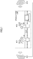
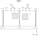
- Base stations BS1 and BS2 are provided to connect the machines and equipment in the production line to the network.
- Machines M1 and M2 used in the production line are equipped with wireless transceiver units WT1 and WT2, respectively, to access at least one of the base stations BS1 and BS2 for the connection to the network.
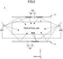
- Equipment used in the production line 3 includes all kinds of equipment involved in the production, such as microdevices including sensors and actuators, assembling equipment, manufacturing machines, or management systems.
- the equipment in the production line 3 is not limited to static devices or machines, but includes mobile devices and machines capable of moving freely in the production line 3.
- the reflective surface 105 of the electromagnetic wave reflector 10 is configured to reflect the radio waves in the frequency band from 1 GHz to 170 GHz.
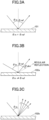
- the reflective surface 105 may include a normal reflector 101, which provides regular reflection with an angle of reflection the same as the angle of incidence, and/or a meta-reflector 102, which has an artificial surface capable of controlling the reflection characteristics of the incident electromagnetic waves.
- a "meta-reflector” is a kind of "metasurface” representing an artificial surface that regulates the transmission and/or reflection characteristics of the incident electromagnetic waves.
- a large number of scatterers sufficiently smaller than the wavelength are arranged in the meta-reflector to regulate the reflection phase distribution and the amplitude distribution, thereby reflecting the incident radio waves in a direction other than that of specular reflection.
- the meta-reflector 102 may be designed so as to provide diffusion and wave-front formation at a predetermined angular distribution, in addition to the meta-reflection in directions other than the specular reflection.
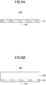
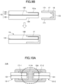
- FIG. 8 shows an example of the electrical connector part 15 of the support body 11 in a cross-sectional view taken along a horizontal plane when the electromagnetic wave reflector 10 stands up on the plane P (see FIG. 7 ).
- the electrical connector part 15 is designed to propagate the reference potential of reflection from one panel to the adjacent panel so that the reference potential of the reflection phenomenon is shared between the adjacent panels 13.
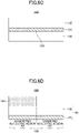
- the CFRP which holds the edge jackets 17-1 and 17-2, serves by itself as the electrical connector part 15A. Electrical connection can be established between the edge jackets 17-1 and 17-2 without using a bridge electrode 112.
- carbon fiber has better reflective performance than bulk metal, and the reflective characteristics of the frame 111A can be improved.
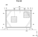
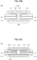
- FIG. 10D shows a configuration of an electrical connector part 15D of a support body 11D.
- the electrical connector part 15D has a bridge electrode 114 that electrically connects the edge jackets 17-1 and 17-2.
- the bridge electrode 114 connects the bottom surfaces 172 of the edge jackets 17-1 and 17-2.
- the configuration of FIG. 10D is advantageous in that the high frequency current can flow in the shortest path from the conductor 131-1 to the along the shortest path through the edge jacket 17-1, the bridge electrode 114, the edge jacket 17-2, and the conductor 131-2.
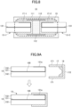
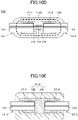
- FIG. 10E shows a configuration using a frame 111E of a composite type of metal and resin.
- the frame 111E has a metal connector 141 and a resin reinforcement 142 that covers the metal connector 141.
- the metal connector 141 can be easily manufactured by extrusion molding or the like, and the connector itself has a certain degree of strength while ensuring electrical connection.
- the resin reinforcement 142 may be formed of an adhesive such as an acrylic adhesive or an epoxy adhesive, thereby reducing the thickness of the metal connector 141 and suppressing residual inductance caused by current detours.
- the corners may be rounded to prevent diffraction at the corners.
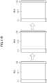
- FIG. 11B shows the state of the electromagnetic wave reflectors 10 before connection.
- a frame 111 having an electrical connector part 15 is attached in advance to one of the side edges of the panel 13, and a guide beam 118 is attached to the other side edge.
- the reflective surfaces 105 of the electromagnetic wave reflector 10-1 to 10-3 may have any configuration shown in FIG. 6A to FIG. 6D .
- a base 119 may be provided in advance to one or both of the guide beam 118 and the frame 111, thereby allowing the connected electromagnetic wave reflectors 10-1 to 10-3 to stand up by themselves on the installation plane.
- a cover 29 may be provided to the edge of the last panel 13 of the electromagnetic wave reflector 10-3 at the end position to protect the edge jacket 17 and the guide beam 118.
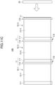
- FIG. 12 and FIG. 13 show a mechanism that reinforces the connections of a plurality of electromagnetic wave reflectors 10-1 and 10-2.
- FIG. 12 (A) is a front view of the electromagnetic wave reflective fence 100, (B) is a side view before the reinforcing mechanism 125 is tightened, and (C) is a side view after the reinforcing mechanism 125 is tightened.
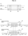
- FIG. 13 shows a configuration example of the reinforcement mechanism 125.
- FIG. 13 shows a front view of guide grooves 129 formed in an attaching surface 127a of a cover 127 of the reinforcement mechanism 125, and cross-sectional views taken along the cross-sections A and B of the front view. The cover 127 is attached to the panels 13 at the attaching surface 127a.
- the mechanism for reinforcing the connection between multiple electromagnetic wave reflectors 10 is not limited to the above-described example shown in FIG. 12 and FIG. 13 , and other appropriate mechanisms including a fastener and a ratchet may be used unless the electromagnetic wave reflection characteristics are impaired.
- the design of the edge jacket 17 and the electrical connector part 15 may be appropriately modified assuming the above-described pressure contact process.
- FIG. 14 shows the size of the meta-reflector 102, assuming that a transmitter "Tx" and a receiver “Rx" are used.
- the transmitter Tx is, for example, a base station BS.
- Receiver Rx is, for example, equipment located in the production line 3.
- the distance from the transmitter Tx to the surface 102s of the meta-reflector 102 is denoted as d1, and the distance from the surface 102s of the meta-reflector 102 to the receiver Rx is denoted as d2.
- the standard length of the production line is 80 m.
- the radius R of the first Fresnel zone is 0.770 m.
- the radius R is 0.588 m.
- the similar estimation applies to the normal reflector 101 because the radius R of the first Fresnel zone does not depend on the relationship between the angle of incidence and the angle of reflection.
- the size of the normal reflector 101 is desirably 50 centimeters per side.
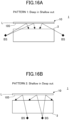
- the meta-reflector 102 is used in a production line covered by a service area with a large aspect ratio, the oblique angle of either incidence or reflection becomes deep. So, the layout and the positional relationship among the production line 3, the base station BS, and the electromagnetic wave reflector 10 will be discussed below.
- FIG. 16B shows Pattern 2 of reflection.
- the base stations BS and the production line 3 are laid in such a positional relationship that the radio waves emitted from the base stations BS are incident onto the reflective surface 105 at a shallow angle with respect to the normal to the reflective surface 105 and are reflected at an angle deeper than the incident angle.
- the radio waves are incident onto the reflective surface 105 at an angle of incidence of 45 degrees or less, and are reflected at an angle greater than the regular reflection.
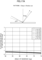
- FIG. 17A shows the baseline robustness of Pattern 1
- FIG. 31B shows the baseline robustness of Pattern 2.
- the baseline robustness means the stability of the angle of reflection when the angle of incidence is changed by 1 degree.
- the baseline robustness is high if the change in the reflection angle is small with respect to the change in the incident angle of 1 degree.
- the base stations BS are preferably located so that the incident angle of the radio waves emitted from the base stations BS and incident onto the electromagnetic wave reflector 10 is 50° or greater, from the viewpoint of suppressing the fluctuation of the reflection angle depending on the incident angle. Therefore, the layout shown in FIG. 17A is preferable to the layout of FIG. 16B .
- FIG. 18 shows quantification of the baseline robustness.
- the baseline robustness of FIG. 17A and FIG. 17B can be estimated by the following procedure.
- a phase jump ⁇ (x) is determined by inputting a certain incident angle ⁇ i and a reflection angle ⁇ r to a function f for calculating a phase jump distribution, where x denotes the position in the x-direction on the reflective surface.
- a phase jump represents the amount of phase to be added to a reflected wave to guide the reflected wave to a desired direction.
- FIG. 17A and FIG. 17B are plots of the calculated fluctuation of the reflection angle as a function of the angle of incidence.
- the equipment in the production line 3 does not always receive only the radio waves reflected from the electromagnetic wave reflector 10, but can receive the radio waves directly from the base station BS. In this case, receive diversity can be achieved by in-phase signal reception. If two base stations BS are provided at both ends of the elongated production line 3, cooperative type base stations may be used.
Landscapes
- Engineering & Computer Science (AREA)
- Computer Networks & Wireless Communication (AREA)
- Physics & Mathematics (AREA)
- Electromagnetism (AREA)
- Signal Processing (AREA)
- Aerials With Secondary Devices (AREA)
Applications Claiming Priority (2)
| Application Number | Priority Date | Filing Date | Title |
|---|---|---|---|
| JP2020064578 | 2020-03-31 | ||
| PCT/JP2020/045592 WO2021199504A1 (ja) | 2020-03-31 | 2020-12-08 | 無線伝達システム |
Publications (3)
| Publication Number | Publication Date |
|---|---|
| EP4131655A1 true EP4131655A1 (de) | 2023-02-08 |
| EP4131655A4 EP4131655A4 (de) | 2024-04-10 |
| EP4131655B1 EP4131655B1 (de) | 2025-11-19 |
Family
ID=77928893
Family Applications (1)
| Application Number | Title | Priority Date | Filing Date |
|---|---|---|---|
| EP20929502.1A Active EP4131655B1 (de) | 2020-03-31 | 2020-12-08 | Drahtloses übertragungssystem |
Country Status (6)
| Country | Link |
|---|---|
| US (1) | US12308521B2 (de) |
| EP (1) | EP4131655B1 (de) |
| JP (1) | JP7548297B2 (de) |
| KR (1) | KR102799656B1 (de) |
| CN (1) | CN115349200B (de) |
| WO (1) | WO2021199504A1 (de) |
Cited By (1)
| Publication number | Priority date | Publication date | Assignee | Title |
|---|---|---|---|---|
| EP4311027A4 (de) * | 2021-03-16 | 2025-03-12 | Agc Inc. | Elektromagnetische wellenreflexionsvorrichtung, elektromagnetische wellenreflexionszaun und verfahren zur montage einer elektromagnetischen wellenreflexionsvorrichtung |
Families Citing this family (27)
| Publication number | Priority date | Publication date | Assignee | Title |
|---|---|---|---|---|
| WO2023012874A1 (ja) * | 2021-08-02 | 2023-02-09 | 日本電信電話株式会社 | 無線通信システム、無線通信システム管理方法、無線通信装置、及び制御装置 |
| FR3128591B1 (fr) * | 2021-10-27 | 2023-09-08 | Psa Automobiles Sa | Dispositif de réflexion à métasurface(s) pour un dispositif de détection d’éléments d’identification |
| WO2023120137A1 (ja) * | 2021-12-20 | 2023-06-29 | Agc株式会社 | 無線伝達システム、及び電磁波反射装置 |
| JPWO2023120138A1 (de) * | 2021-12-20 | 2023-06-29 | ||
| JP7816388B2 (ja) * | 2022-02-07 | 2026-02-18 | Agc株式会社 | 電磁波反射装置、電磁波反射フェンス、電磁波反射装置の設置方法、及び電磁波反射フェンスの設置方法 |
| EP4525211A1 (de) | 2022-05-09 | 2025-03-19 | Agc Inc. | Vorrichtung zur reflexion elektromagnetischer wellen und reflexionszaun für elektromagnetische wellen |
| JPWO2023228693A1 (de) * | 2022-05-24 | 2023-11-30 | ||
| US20250357675A1 (en) * | 2022-05-31 | 2025-11-20 | Kyocera Corporation | Radio wave control plate and communication system |
| KR20250018470A (ko) * | 2022-06-01 | 2025-02-06 | 에이지씨 가부시키가이샤 | 전자파 반사 장치, 전자파 반사 펜스 및 반사 패널 |
| CN119156746A (zh) * | 2022-06-01 | 2024-12-17 | Agc株式会社 | 电磁波反射装置、电磁波反射围栏以及反射面板 |
| WO2023233921A1 (ja) * | 2022-06-01 | 2023-12-07 | Agc株式会社 | 電磁波反射装置、電磁波反射フェンス、及び反射パネル |
| JPWO2023233879A1 (de) * | 2022-06-01 | 2023-12-07 | ||
| JP7405316B1 (ja) * | 2022-06-27 | 2023-12-26 | 大日本印刷株式会社 | 反射構造体、反射構造体の製造方法、および周波数選択反射板セット |
| JPWO2024029325A1 (de) * | 2022-08-03 | 2024-02-08 | ||
| JPWO2024038682A1 (de) * | 2022-08-17 | 2024-02-22 | ||
| WO2024038775A1 (ja) * | 2022-08-17 | 2024-02-22 | Agc株式会社 | 反射パネル、電磁波反射装置、及び電磁波反射フェンス |
| JPWO2024048443A1 (de) * | 2022-09-02 | 2024-03-07 | ||
| JPWO2024070407A1 (de) * | 2022-09-26 | 2024-04-04 | ||
| JP7727605B2 (ja) * | 2022-09-27 | 2025-08-21 | Kddi株式会社 | 反射板及び反射装置 |
| JPWO2024135455A1 (de) * | 2022-12-21 | 2024-06-27 | ||
| CN120380665A (zh) * | 2022-12-27 | 2025-07-25 | Agc株式会社 | 无线传输系统 |
| JPWO2024190085A1 (de) * | 2023-03-14 | 2024-09-19 | ||
| WO2024241665A1 (ja) * | 2023-05-23 | 2024-11-28 | Agc株式会社 | 電磁波反射パネル、電磁波反射装置、及び電磁波反射フェンス |
| WO2024247411A1 (ja) * | 2023-05-29 | 2024-12-05 | Agc株式会社 | 電磁波反射装置、電磁波反射フェンス、及び電磁波反射パネルの設置方法 |
| WO2025041555A1 (ja) * | 2023-08-21 | 2025-02-27 | Agc株式会社 | 電磁波反射パネル、これを用いた電磁波反射装置、電磁波反射フェンス、電磁波反射パネルの製造方法、及び電磁波反射パネルの評価方法 |
| CN116946328B (zh) * | 2023-09-20 | 2023-12-29 | 江苏锦程船舶制造有限公司 | 一种救援无人船 |
| WO2025105137A1 (ja) * | 2023-11-13 | 2025-05-22 | Agc株式会社 | 無線伝達システム |
Family Cites Families (23)
| Publication number | Priority date | Publication date | Assignee | Title |
|---|---|---|---|---|
| US6323601B1 (en) * | 2000-09-11 | 2001-11-27 | Nordson Corporation | Reflector for an ultraviolet lamp system |
| US6559460B1 (en) * | 2000-10-31 | 2003-05-06 | Nordson Corporation | Ultraviolet lamp system and methods |
| US6732451B2 (en) * | 2001-04-11 | 2004-05-11 | Intermec Ip Corp. | UV curing module for label printer |
| JP2003249872A (ja) * | 2002-02-22 | 2003-09-05 | Sharp Corp | 無線通信システム |
| JP4235010B2 (ja) * | 2003-02-26 | 2009-03-04 | Tdk株式会社 | 不要電波抑制構造 |
| JP4301893B2 (ja) * | 2003-08-07 | 2009-07-22 | 積水樹脂株式会社 | 電波吸収パネル |
| JP4410695B2 (ja) * | 2005-02-10 | 2010-02-03 | 株式会社神戸製鋼所 | 無線lanシステムおよびそのアンテナモジュール |
| JP4445883B2 (ja) * | 2005-02-28 | 2010-04-07 | Necエンジニアリング株式会社 | 無線式データキャリア書込読取システム |
| JP4892207B2 (ja) | 2005-07-25 | 2012-03-07 | 鹿島建設株式会社 | 透光性電磁波シールド板の接合構造及び接合具 |
| US7909595B2 (en) * | 2006-03-17 | 2011-03-22 | Applied Materials, Inc. | Apparatus and method for exposing a substrate to UV radiation using a reflector having both elliptical and parabolic reflective sections |
| JP4609373B2 (ja) * | 2006-04-28 | 2011-01-12 | 日本電気株式会社 | Rfid通信システム及びrfid通信方法 |
| JP4407720B2 (ja) * | 2006-06-09 | 2010-02-03 | 日本電気株式会社 | 無線通信システム及び無線通信方法 |
| JP4853329B2 (ja) * | 2007-02-28 | 2012-01-11 | 株式会社豊田中央研究所 | 電波反射板及びアンテナ |
| US7991257B1 (en) * | 2007-05-16 | 2011-08-02 | Fusion Optix, Inc. | Method of manufacturing an optical composite |
| US9190738B2 (en) * | 2010-04-11 | 2015-11-17 | Broadcom Corporation | Projected artificial magnetic mirror |
| JP5606283B2 (ja) * | 2010-11-10 | 2014-10-15 | 三菱電機株式会社 | 無線装置 |
| JP2016042222A (ja) * | 2014-08-14 | 2016-03-31 | 株式会社マーストーケンソリューション | 搬送コンベア用rfidシステム |
| CN110313137B (zh) * | 2017-02-21 | 2022-06-14 | 3M创新有限公司 | 无源中继器设备、微波网络及设计中继器设备的方法 |
| US10547116B2 (en) * | 2017-08-01 | 2020-01-28 | University Of Cyprus | Wireless communication paradigm: realizing programmable wireless environments through software-controlled metasurfaces |
| US11342682B2 (en) * | 2018-05-24 | 2022-05-24 | Metawave Corporation | Frequency-selective reflector module and system |
| JP2020064578A (ja) | 2018-10-15 | 2020-04-23 | 株式会社エモスタ | 価値観定量化装置及びこれを利用したマッチング・リコメンデーション方法 |
| EP4131640A4 (de) * | 2020-03-31 | 2024-04-03 | Agc Inc. | Vorrichtung zur reflexion elektromagnetischer wellen, reflexionszaun für elektromagnetische wellen und verfahren zur montage der vorrichtung zur reflexion elektromagnetischer wellen |
| CN111983560B (zh) * | 2020-08-05 | 2022-12-30 | 北京理工大学 | 一种双可重构智能表面辅助的毫米波单基站定位方法 |
-
2020
- 2020-12-08 EP EP20929502.1A patent/EP4131655B1/de active Active
- 2020-12-08 CN CN202080099140.2A patent/CN115349200B/zh active Active
- 2020-12-08 WO PCT/JP2020/045592 patent/WO2021199504A1/ja not_active Ceased
- 2020-12-08 JP JP2022511523A patent/JP7548297B2/ja active Active
- 2020-12-08 KR KR1020227031307A patent/KR102799656B1/ko active Active
-
2022
- 2022-09-23 US US17/934,820 patent/US12308521B2/en active Active
Cited By (2)
| Publication number | Priority date | Publication date | Assignee | Title |
|---|---|---|---|---|
| EP4311027A4 (de) * | 2021-03-16 | 2025-03-12 | Agc Inc. | Elektromagnetische wellenreflexionsvorrichtung, elektromagnetische wellenreflexionszaun und verfahren zur montage einer elektromagnetischen wellenreflexionsvorrichtung |
| US12368243B2 (en) | 2021-03-16 | 2025-07-22 | AGC Inc. | Electromagnetic wave reflector, reflected electromagnetic wave fence, and method of assembling electromagnetic wave reflector |
Also Published As
| Publication number | Publication date |
|---|---|
| US20230010669A1 (en) | 2023-01-12 |
| EP4131655B1 (de) | 2025-11-19 |
| KR102799656B1 (ko) | 2025-04-23 |
| CN115349200A (zh) | 2022-11-15 |
| JP7548297B2 (ja) | 2024-09-10 |
| WO2021199504A1 (ja) | 2021-10-07 |
| KR20220161287A (ko) | 2022-12-06 |
| EP4131655A4 (de) | 2024-04-10 |
| CN115349200B (zh) | 2026-03-17 |
| JPWO2021199504A1 (de) | 2021-10-07 |
| US12308521B2 (en) | 2025-05-20 |
Similar Documents
| Publication | Publication Date | Title |
|---|---|---|
| EP4131655B1 (de) | Drahtloses übertragungssystem | |
| US12355154B2 (en) | Electromagnetic wave reflector, electromagnetic wave reflective fence, and method of assembling electromagnetic wave reflector | |
| US12368243B2 (en) | Electromagnetic wave reflector, reflected electromagnetic wave fence, and method of assembling electromagnetic wave reflector | |
| US20250309551A1 (en) | Radio transmission system | |
| US11355836B2 (en) | Combined antenna and radome arrangement | |
| US20260051662A1 (en) | Radio wave lens | |
| WO2023120138A1 (ja) | 無線伝達システム、及び電磁波反射装置 | |
| US20260100506A1 (en) | Passive reflectors providing phase distribution and methods of fabricating the same | |
| CN206585071U (zh) | 低剖面天线 | |
| JP7730418B2 (ja) | 通信システム、電波屈折板および電波屈折板の設置位置の算出方法 | |
| WO2025105163A1 (ja) | 無線伝達システム | |
| WO2026058743A1 (ja) | 電磁波反射装置、電磁波反射フェンス、及び電磁波反射装置の組み立て方法 | |
| WO2025158772A1 (ja) | 無線伝達システム | |
| WO2025115482A1 (ja) | 受信電力の測定方法、電力反射効率の計算方法、受信電力の測定プログラム、及び、電力反射効率の計算プログラム | |
| WO2023120137A1 (ja) | 無線伝達システム、及び電磁波反射装置 | |
| WO2022239660A1 (ja) | リフレクタシステム、アクティブリフレクタ、及び、アクティブリフレクタの配置方法 | |
| WO2025105137A1 (ja) | 無線伝達システム | |
| JP2026013766A (ja) | 電磁波反射装置、電磁波反射フェンス、及び、無線伝達システム | |
| TW202410553A (zh) | 反射板、電磁波反射裝置及電磁波反射柵 | |
| KR20190009685A (ko) | 렌즈 및 필름층을 포함하는 안테나 조립체 | |
| CN108270073A (zh) | 低剖面天线 |
Legal Events
| Date | Code | Title | Description |
|---|---|---|---|
| STAA | Information on the status of an ep patent application or granted ep patent |
Free format text: STATUS: THE INTERNATIONAL PUBLICATION HAS BEEN MADE |
|
| PUAI | Public reference made under article 153(3) epc to a published international application that has entered the european phase |
Free format text: ORIGINAL CODE: 0009012 |
|
| STAA | Information on the status of an ep patent application or granted ep patent |
Free format text: STATUS: REQUEST FOR EXAMINATION WAS MADE |
|
| 17P | Request for examination filed |
Effective date: 20220929 |
|
| AK | Designated contracting states |
Kind code of ref document: A1 Designated state(s): AL AT BE BG CH CY CZ DE DK EE ES FI FR GB GR HR HU IE IS IT LI LT LU LV MC MK MT NL NO PL PT RO RS SE SI SK SM TR |
|
| DAV | Request for validation of the european patent (deleted) | ||
| DAX | Request for extension of the european patent (deleted) | ||
| A4 | Supplementary search report drawn up and despatched |
Effective date: 20240311 |
|
| RIC1 | Information provided on ipc code assigned before grant |
Ipc: H01Q 1/36 20060101ALN20240304BHEP Ipc: H01Q 19/10 20060101ALI20240304BHEP Ipc: H01Q 3/46 20060101ALI20240304BHEP Ipc: H04B 7/145 20060101ALI20240304BHEP Ipc: H04B 7/04 20170101ALI20240304BHEP Ipc: H01Q 19/18 20060101ALI20240304BHEP Ipc: H01Q 15/00 20060101ALI20240304BHEP Ipc: H01Q 15/14 20060101AFI20240304BHEP |
|
| GRAP | Despatch of communication of intention to grant a patent |
Free format text: ORIGINAL CODE: EPIDOSNIGR1 |
|
| STAA | Information on the status of an ep patent application or granted ep patent |
Free format text: STATUS: GRANT OF PATENT IS INTENDED |
|
| RIC1 | Information provided on ipc code assigned before grant |
Ipc: H01Q 15/14 20060101AFI20250627BHEP Ipc: H01Q 15/00 20060101ALI20250627BHEP Ipc: H01Q 19/18 20060101ALI20250627BHEP Ipc: H04B 7/04 20170101ALI20250627BHEP Ipc: H04B 7/145 20060101ALI20250627BHEP Ipc: H01Q 3/46 20060101ALI20250627BHEP Ipc: H01Q 19/10 20060101ALI20250627BHEP Ipc: H01Q 1/36 20060101ALN20250627BHEP |
|
| RIC1 | Information provided on ipc code assigned before grant |
Ipc: H01Q 15/14 20060101AFI20250709BHEP Ipc: H01Q 15/00 20060101ALI20250709BHEP Ipc: H01Q 19/18 20060101ALI20250709BHEP Ipc: H04B 7/04 20170101ALI20250709BHEP Ipc: H04B 7/145 20060101ALI20250709BHEP Ipc: H01Q 3/46 20060101ALI20250709BHEP Ipc: H01Q 19/10 20060101ALI20250709BHEP Ipc: H01Q 1/36 20060101ALN20250709BHEP |
|
| INTG | Intention to grant announced |
Effective date: 20250716 |
|
| P01 | Opt-out of the competence of the unified patent court (upc) registered |
Free format text: CASE NUMBER: UPC_APP_5706_4131655/2025 Effective date: 20250903 |
|
| GRAS | Grant fee paid |
Free format text: ORIGINAL CODE: EPIDOSNIGR3 |
|
| GRAA | (expected) grant |
Free format text: ORIGINAL CODE: 0009210 |
|
| STAA | Information on the status of an ep patent application or granted ep patent |
Free format text: STATUS: THE PATENT HAS BEEN GRANTED |
|
| AK | Designated contracting states |
Kind code of ref document: B1 Designated state(s): AL AT BE BG CH CY CZ DE DK EE ES FI FR GB GR HR HU IE IS IT LI LT LU LV MC MK MT NL NO PL PT RO RS SE SI SK SM TR |
|
| REG | Reference to a national code |
Ref country code: CH Ref legal event code: F10 Free format text: ST27 STATUS EVENT CODE: U-0-0-F10-F00 (AS PROVIDED BY THE NATIONAL OFFICE) Effective date: 20251119 Ref country code: GB Ref legal event code: FG4D |
|
| REG | Reference to a national code |
Ref country code: DE Ref legal event code: R096 Ref document number: 602020062606 Country of ref document: DE |
|
| REG | Reference to a national code |
Ref country code: IE Ref legal event code: FG4D |
|
| REG | Reference to a national code |
Ref country code: NL Ref legal event code: MP Effective date: 20251119 |
|
| PG25 | Lapsed in a contracting state [announced via postgrant information from national office to epo] |
Ref country code: ES Free format text: LAPSE BECAUSE OF FAILURE TO SUBMIT A TRANSLATION OF THE DESCRIPTION OR TO PAY THE FEE WITHIN THE PRESCRIBED TIME-LIMIT Effective date: 20251119 |
|
| REG | Reference to a national code |
Ref country code: LT Ref legal event code: MG9D |
|
| PG25 | Lapsed in a contracting state [announced via postgrant information from national office to epo] |
Ref country code: NO Free format text: LAPSE BECAUSE OF FAILURE TO SUBMIT A TRANSLATION OF THE DESCRIPTION OR TO PAY THE FEE WITHIN THE PRESCRIBED TIME-LIMIT Effective date: 20260219 |
|
| PGFP | Annual fee paid to national office [announced via postgrant information from national office to epo] |
Ref country code: DE Payment date: 20251223 Year of fee payment: 6 |
|
| PG25 | Lapsed in a contracting state [announced via postgrant information from national office to epo] |
Ref country code: HR Free format text: LAPSE BECAUSE OF FAILURE TO SUBMIT A TRANSLATION OF THE DESCRIPTION OR TO PAY THE FEE WITHIN THE PRESCRIBED TIME-LIMIT Effective date: 20251119 Ref country code: AT Free format text: LAPSE BECAUSE OF FAILURE TO SUBMIT A TRANSLATION OF THE DESCRIPTION OR TO PAY THE FEE WITHIN THE PRESCRIBED TIME-LIMIT Effective date: 20251119 Ref country code: FI Free format text: LAPSE BECAUSE OF FAILURE TO SUBMIT A TRANSLATION OF THE DESCRIPTION OR TO PAY THE FEE WITHIN THE PRESCRIBED TIME-LIMIT Effective date: 20251119 |
|
| REG | Reference to a national code |
Ref country code: AT Ref legal event code: MK05 Ref document number: 1859701 Country of ref document: AT Kind code of ref document: T Effective date: 20251119 |
|
| PG25 | Lapsed in a contracting state [announced via postgrant information from national office to epo] |
Ref country code: NL Free format text: LAPSE BECAUSE OF FAILURE TO SUBMIT A TRANSLATION OF THE DESCRIPTION OR TO PAY THE FEE WITHIN THE PRESCRIBED TIME-LIMIT Effective date: 20251119 |
|
| PG25 | Lapsed in a contracting state [announced via postgrant information from national office to epo] |
Ref country code: RS Free format text: LAPSE BECAUSE OF FAILURE TO SUBMIT A TRANSLATION OF THE DESCRIPTION OR TO PAY THE FEE WITHIN THE PRESCRIBED TIME-LIMIT Effective date: 20260219 |
|
| PG25 | Lapsed in a contracting state [announced via postgrant information from national office to epo] |
Ref country code: IS Free format text: LAPSE BECAUSE OF FAILURE TO SUBMIT A TRANSLATION OF THE DESCRIPTION OR TO PAY THE FEE WITHIN THE PRESCRIBED TIME-LIMIT Effective date: 20260319 |