EP4131631B1 - Elektrodenanordnung, batteriezelle, batterie und stromverbrauchende vorrichtung - Google Patents
Elektrodenanordnung, batteriezelle, batterie und stromverbrauchende vorrichtung Download PDFInfo
- Publication number
- EP4131631B1 EP4131631B1 EP21913437.6A EP21913437A EP4131631B1 EP 4131631 B1 EP4131631 B1 EP 4131631B1 EP 21913437 A EP21913437 A EP 21913437A EP 4131631 B1 EP4131631 B1 EP 4131631B1
- Authority
- EP
- European Patent Office
- Prior art keywords
- body portion
- tab
- zone
- electrode plate
- end portion
- Prior art date
- Legal status (The legal status is an assumption and is not a legal conclusion. Google has not performed a legal analysis and makes no representation as to the accuracy of the status listed.)
- Active
Links
Images


Classifications
-
- H—ELECTRICITY
- H01—ELECTRIC ELEMENTS
- H01M—PROCESSES OR MEANS, e.g. BATTERIES, FOR THE DIRECT CONVERSION OF CHEMICAL ENERGY INTO ELECTRICAL ENERGY
- H01M50/00—Constructional details or processes of manufacture of the non-active parts of electrochemical cells other than fuel cells, e.g. hybrid cells
- H01M50/50—Current conducting connections for cells or batteries
- H01M50/572—Means for preventing undesired use or discharge
- H01M50/584—Means for preventing undesired use or discharge for preventing incorrect connections inside or outside the batteries
- H01M50/59—Means for preventing undesired use or discharge for preventing incorrect connections inside or outside the batteries characterised by the protection means
- H01M50/593—Spacers; Insulating plates
-
- H—ELECTRICITY
- H01—ELECTRIC ELEMENTS
- H01M—PROCESSES OR MEANS, e.g. BATTERIES, FOR THE DIRECT CONVERSION OF CHEMICAL ENERGY INTO ELECTRICAL ENERGY
- H01M10/00—Secondary cells; Manufacture thereof
- H01M10/05—Accumulators with non-aqueous electrolyte
- H01M10/058—Construction or manufacture
- H01M10/0583—Construction or manufacture of accumulators with folded construction elements except wound ones, i.e. folded positive or negative electrodes or separators, e.g. with "Z"-shaped electrodes or separators
-
- H—ELECTRICITY
- H01—ELECTRIC ELEMENTS
- H01M—PROCESSES OR MEANS, e.g. BATTERIES, FOR THE DIRECT CONVERSION OF CHEMICAL ENERGY INTO ELECTRICAL ENERGY
- H01M10/00—Secondary cells; Manufacture thereof
- H01M10/04—Construction or manufacture in general
- H01M10/045—Cells or batteries with folded plate-like electrodes
-
- H—ELECTRICITY
- H01—ELECTRIC ELEMENTS
- H01M—PROCESSES OR MEANS, e.g. BATTERIES, FOR THE DIRECT CONVERSION OF CHEMICAL ENERGY INTO ELECTRICAL ENERGY
- H01M10/00—Secondary cells; Manufacture thereof
- H01M10/04—Construction or manufacture in general
- H01M10/0459—Cells or batteries with folded separator between plate-like electrodes
-
- H—ELECTRICITY
- H01—ELECTRIC ELEMENTS
- H01M—PROCESSES OR MEANS, e.g. BATTERIES, FOR THE DIRECT CONVERSION OF CHEMICAL ENERGY INTO ELECTRICAL ENERGY
- H01M10/00—Secondary cells; Manufacture thereof
- H01M10/05—Accumulators with non-aqueous electrolyte
- H01M10/058—Construction or manufacture
- H01M10/0587—Construction or manufacture of accumulators having only wound construction elements, i.e. wound positive electrodes, wound negative electrodes and wound separators
-
- H—ELECTRICITY
- H01—ELECTRIC ELEMENTS
- H01M—PROCESSES OR MEANS, e.g. BATTERIES, FOR THE DIRECT CONVERSION OF CHEMICAL ENERGY INTO ELECTRICAL ENERGY
- H01M10/00—Secondary cells; Manufacture thereof
- H01M10/42—Methods or arrangements for servicing or maintenance of secondary cells or secondary half-cells
- H01M10/4235—Safety or regulating additives or arrangements in electrodes, separators or electrolyte
-
- H—ELECTRICITY
- H01—ELECTRIC ELEMENTS
- H01M—PROCESSES OR MEANS, e.g. BATTERIES, FOR THE DIRECT CONVERSION OF CHEMICAL ENERGY INTO ELECTRICAL ENERGY
- H01M50/00—Constructional details or processes of manufacture of the non-active parts of electrochemical cells other than fuel cells, e.g. hybrid cells
- H01M50/50—Current conducting connections for cells or batteries
- H01M50/531—Electrode connections inside a battery casing
- H01M50/538—Connection of several leads or tabs of wound or folded electrode stacks
-
- H—ELECTRICITY
- H01—ELECTRIC ELEMENTS
- H01M—PROCESSES OR MEANS, e.g. BATTERIES, FOR THE DIRECT CONVERSION OF CHEMICAL ENERGY INTO ELECTRICAL ENERGY
- H01M50/00—Constructional details or processes of manufacture of the non-active parts of electrochemical cells other than fuel cells, e.g. hybrid cells
- H01M50/50—Current conducting connections for cells or batteries
- H01M50/572—Means for preventing undesired use or discharge
- H01M50/584—Means for preventing undesired use or discharge for preventing incorrect connections inside or outside the batteries
- H01M50/586—Means for preventing undesired use or discharge for preventing incorrect connections inside or outside the batteries inside the batteries, e.g. incorrect connections of electrodes
-
- H—ELECTRICITY
- H01—ELECTRIC ELEMENTS
- H01M—PROCESSES OR MEANS, e.g. BATTERIES, FOR THE DIRECT CONVERSION OF CHEMICAL ENERGY INTO ELECTRICAL ENERGY
- H01M50/00—Constructional details or processes of manufacture of the non-active parts of electrochemical cells other than fuel cells, e.g. hybrid cells
- H01M50/50—Current conducting connections for cells or batteries
- H01M50/572—Means for preventing undesired use or discharge
- H01M50/584—Means for preventing undesired use or discharge for preventing incorrect connections inside or outside the batteries
- H01M50/59—Means for preventing undesired use or discharge for preventing incorrect connections inside or outside the batteries characterised by the protection means
- H01M50/595—Tapes
-
- H—ELECTRICITY
- H01—ELECTRIC ELEMENTS
- H01M—PROCESSES OR MEANS, e.g. BATTERIES, FOR THE DIRECT CONVERSION OF CHEMICAL ENERGY INTO ELECTRICAL ENERGY
- H01M2220/00—Batteries for particular applications
- H01M2220/20—Batteries in motive systems, e.g. vehicle, ship, plane
-
- H—ELECTRICITY
- H01—ELECTRIC ELEMENTS
- H01M—PROCESSES OR MEANS, e.g. BATTERIES, FOR THE DIRECT CONVERSION OF CHEMICAL ENERGY INTO ELECTRICAL ENERGY
- H01M50/00—Constructional details or processes of manufacture of the non-active parts of electrochemical cells other than fuel cells, e.g. hybrid cells
- H01M50/20—Mountings; Secondary casings or frames; Racks, modules or packs; Suspension devices; Shock absorbers; Transport or carrying devices; Holders
- H01M50/249—Mountings; Secondary casings or frames; Racks, modules or packs; Suspension devices; Shock absorbers; Transport or carrying devices; Holders specially adapted for aircraft or vehicles, e.g. cars or trains
-
- Y—GENERAL TAGGING OF NEW TECHNOLOGICAL DEVELOPMENTS; GENERAL TAGGING OF CROSS-SECTIONAL TECHNOLOGIES SPANNING OVER SEVERAL SECTIONS OF THE IPC; TECHNICAL SUBJECTS COVERED BY FORMER USPC CROSS-REFERENCE ART COLLECTIONS [XRACs] AND DIGESTS
- Y02—TECHNOLOGIES OR APPLICATIONS FOR MITIGATION OR ADAPTATION AGAINST CLIMATE CHANGE
- Y02E—REDUCTION OF GREENHOUSE GAS [GHG] EMISSIONS, RELATED TO ENERGY GENERATION, TRANSMISSION OR DISTRIBUTION
- Y02E60/00—Enabling technologies; Technologies with a potential or indirect contribution to GHG emissions mitigation
- Y02E60/10—Energy storage using batteries
-
- Y—GENERAL TAGGING OF NEW TECHNOLOGICAL DEVELOPMENTS; GENERAL TAGGING OF CROSS-SECTIONAL TECHNOLOGIES SPANNING OVER SEVERAL SECTIONS OF THE IPC; TECHNICAL SUBJECTS COVERED BY FORMER USPC CROSS-REFERENCE ART COLLECTIONS [XRACs] AND DIGESTS
- Y02—TECHNOLOGIES OR APPLICATIONS FOR MITIGATION OR ADAPTATION AGAINST CLIMATE CHANGE
- Y02P—CLIMATE CHANGE MITIGATION TECHNOLOGIES IN THE PRODUCTION OR PROCESSING OF GOODS
- Y02P70/00—Climate change mitigation technologies in the production process for final industrial or consumer products
- Y02P70/50—Manufacturing or production processes characterised by the final manufactured product
Definitions
- This application relates to the field of batteries, and in particular, to an electrode assembly as specificed in any of claims 1-9, a battery cell as specified in cliam 10, a battery as specified in cliam 11, and an electric apparatus as specified in claim 12.
- This application provides an electrode assembly, a battery cell, a battery, and an electric apparatus, which can reduce a risk of short circuits and improve safety performance.
- this application provides an electrode assembly, which includes: at least one first electrode plate including a first body portion and a first tab, where the first body portion has a first end portion in a first direction, and the first tab is connected to the first end portion; and at least one second electrode plate, whose polarity is opposite to that of the first electrode plate, where the second electrode plate includes a second body portion and a second insulation portion connected to the second body portion, the first body portion and the second body portion are stacked in a direction perpendicular to the first direction, the second body portion has a second end portion close to the first tab in the first direction, and the second insulation portion covers at least part of the second end portion so as to separate the first tab from the second end portion when the first tab is bent;
- the second insulation portion is provided to reduce a risk of the first tab contacting the second end portion when the first tab is bent, improving safety performance of the electrode assembly.
- the second connection zone can reduce a risk of the first tab contacting the second body portion when the first tab is inserted between the first body portion and the second body portion, improving safety performance.
- the second connection zone is provided in two, which are disposed on two sides of the second body portion in a stacking direction respectively.
- the two second connection zones can increase connection area between the second insulation portion and the second body portion, enhancing connection strength between the second insulation portion and the second body portion and reducing a risk of the second insulation portion coming off.
- a ratio of a size of the second connection zone in the first direction to a size of the second body portion in the first direction ranges from 0.5% to 6%.
- the first insulation portion can cover at least part of the first end portion, thereby reducing a risk of burrs on the first end portion piercing a separator and improving safety performance.
- a portion of the second active material layer that is not covered by the second connection zone can cover a portion of the first active material layer that is not covered by the first connection zone, providing more space to intercalate the metal ions and reducing a risk of lithium precipitation.
- a gap between the edge of the second connection zone farther away from the second coverage zone and the edge of the first connection zone farther away from the first coverage zone is greater than 0.05 mm, so that the portion of the second active material layer that is not covered by the second connection zone has a larger area for intercalating more metal ions, thereby reducing the risk of lithium precipitation.
- the first body portion includes a first current collection zone, a first active material layer, and a first protective layer, where the first active material layer is applied on a surface of the first current collection zone, and the first protective layer is applied on a surface of the first current collection zone and connected to the first active material layer.
- the first protective layer is located on a side of the first active material layer in the first direction and close to the first tab.
- the first connection zone is fixed on the first protective layer, and in a direction farther away from the first tab and parallel to the first direction, an edge of the first connection zone farther away from the first coverage zone does not exceed the first protective layer.
- the first connection zone does not cover the first active material layer so that the first connection zone does not obstruct deintercalating metal ions from the first active material layer, improving cycling performance of the electrode assembly.
- the first body portion has a third end portion in the first direction farther away from the first end portion, and the second body portion has a fourth end portion in the first direction farther away from the second end portion.
- the second electrode plate further includes a second tab, where the second tab is connected to the second end portion or the fourth end portion.
- the first electrode plate further includes a third insulation portion, where the third insulation portion is connected to the first body portion and covers at least part of the third end portion.
- the third insulation portion can reduce a risk of burrs on the third end portion piercing a separator, improving safety performance.
- the second electrode plate further includes a fourth insulation portion, where the fourth insulation portion is connected to the second body portion and covers at least part of the fourth end portion.
- the fourth insulation portion can reduce a risk of burrs on the fourth end portion piercing a separator, improving safety performance.
- the second insulation portion has a porous structure for metal ions to pass through.
- the metal ions are able to pass through the second insulation portion to reduce resistance of the second insulation portion to transport the metal ions, helping intercalate and deintercalate the metal ions.
- the electrode assembly further includes a separator configured to separate the first electrode plate from the second electrode plate. Thickness of the second insulation portion is greater than thickness of the separator. The second insulation portion has greater thickness and strength than the separator, and is difficult to be pierced by burrs on the second end portion, thus reducing a risk of short circuits.
- this application provides a battery cell as specified in cliam 10, which includes: a housing with an accommodating cavity and an opening; at least one electrode assembly according to any one of the embodiments in the first aspect accommodated in the accommodating cavity; and a cover plate configured to close the opening of the housing.
- this application further provides a battery as specified in cliam 11, including a box body; and at least one battery cell according to the second aspect, where the battery cell is accommodated in the box body.
- this application further provides an electric apparatus as specified in cliam 12, where the electric apparatus is configured to receive power supplied by the battery according to the third aspect.
- the terms “installment”, “link”, “connection”, and “attachment” should be understood in their general senses.
- the terms may be a fixed connection, a detachable connection, or an integrated connection, or may be a direct connection, an indirect connection through an intermediate medium, or an internal connection between two elements.
- a and/or B may represent the following three cases: A alone, both A and B, and B alone.
- the character "/" in this application generally indicates an "or" relationship between the associated objects.
- a plurality of means two (inclusive) or more.
- a plurality of groups means two (inclusive) or more groups, and "a plurality of pieces” means two (inclusive) or more pieces.
- parallel includes not only absolute parallel but also approximately parallel commonly known in engineering.
- vertical also includes not only absolute vertical but also approximately vertical commonly known in engineering.
- a battery cell may include a lithium-ion secondary battery cell, a lithium-ion primary battery cell, a lithium-sulfur battery cell, a sodium-lithium-ion battery cell, a sodium-ion battery cell, a magnesium-ion battery cell, or the like.
- the battery cell may be cylindrical, flat, rectangular, or in another shape, and this is also not limited in the embodiments of this application.
- Battery cells are usually categorized into three types depending on their packaging: cylinder battery cell, prismatic battery cell, and pouch battery cell, and this is also not limited in the embodiments of this application.
- the battery mentioned in the embodiments of this application is a single physical module that includes one or more battery cells for providing a higher voltage and capacity.
- the battery mentioned in this application may include a battery module, a battery pack, or the like.
- a battery generally includes a box body configured to package one or more battery cells. The box body can prevent a liquid or another foreign matter from affecting charging or discharging of the battery cell.
- the battery cell and the battery described in the embodiments of this application are both applicable to electric apparatuses.
- the battery cell and the battery supply electric power to the electric apparatuses.
- an electric apparatus may be a mobile phone, a portable device, a laptop, an electric scooter, an electric vehicle, a steamship, a spacecraft, an electric toy, an electric tool, and the like.
- the spacecraft includes an airplane, a rocket, a space shuttle, a spaceship, and the like.
- the electric toy includes a fixed or mobile electric toy, such as a game console, an electric vehicle toy, an electric ship toy, and an electric airplane toy.
- the electric tool includes an electric metal cutting tool, an electric grinding tool, an electric assembly tool, and an electric railway-specific tool, such as an electric drill, an electric grinder, an electric wrench, an electric screwdriver, an electric hammer, an electric impact drill, a concrete vibrator, and an electric planer.
- an electric drill such as an electric drill, an electric grinder, an electric wrench, an electric screwdriver, an electric hammer, an electric impact drill, a concrete vibrator, and an electric planer.
- FIG. 1 is a schematic structural diagram of a vehicle 1 according to an embodiment of this application.
- the vehicle 1 may be an oil-fueled vehicle, a gas-powered vehicle, or a new energy vehicle.
- the new energy vehicle may be a battery electric vehicle, a hybrid electric vehicle, an extended-range electric vehicle, or the like.
- a battery 2, a controller 3, and a motor 4 may be disposed inside the vehicle 1, and the controller 3 is configured to control the battery 2 to supply power to the motor 4.
- a battery 2 may be disposed at the bottom, the front, or the rear of the vehicle 1.
- the battery 2 may be configured to supply power to the vehicle 1.
- the battery 2 may be used as an operational power supply for the vehicle 1, and may be applied to a circuit system of the vehicle 1, for example, may be configured to supply power to meet the start, navigation, and driving requirements of the vehicle 1.
- the battery 2 not only can be used as the operational power supply for the vehicle 1, but also can be used as a driving power supply for the vehicle 1, to totally or partially replace the fossil fuel or the natural gas to provide driving power for the vehicle 1.
- the battery 2 may include a plurality of battery cells, where the plurality of battery cells may be connected in series, in parallel, or in series and parallel, and being connected in series and parallel is a combination of series and parallel connections.
- the plurality of battery cells may be directly connected in series, in parallel, or in series and parallel.
- the plurality of battery cells may be connected in series, in parallel, or in series and parallel to form a battery module first, and then a plurality of battery modules are connected in series, in parallel, or in series and parallel to form a battery 2.
- the plurality of battery cells may directly constitute a battery 2, or may first constitute a battery module, and then a plurality of battery modules constitute a battery 2.
- FIG. 2 is a schematic structural diagram of a battery 2 according to an embodiment of this application.
- the battery 2 may include a plurality of battery cells 5.
- the battery 2 may further include a box body (or referred to as a cover body), an inside of the box body is a hollow structure, and the plurality of battery cells 5 are accommodated in the box body.
- the box body may include two portions, which are referred to as a first box body portion 61 and a second box body portion 62 respectively herein, and the first box body portion 61 and the second box body portion 62 are snap-fitted together.
- Shapes of the first box body portion 61 and the second box body portion 62 may be determined based on a shape of a structure formed by combining the plurality of battery cells 5, and the first box body portion 61 and the second box body portion 62 each may have an opening.
- the first box body portion 61 and the second box body portion 62 each may be a hollow cuboid and have only one face with an opening, the opening of the first box body portion 61 is disposed opposite the opening of the second box body portion 62, and the first box body portion 61 and the second box body portion 62 are snap-fitted to form a box body with an enclosed chamber.
- the plurality of battery cells 5 are connected in parallel, series, or series and parallel, they are placed in the box body formed after the first box body portion 61 and the second box body portion 62 are snap-fitted together.
- the battery 2 may further include other structures. Details are not described herein.
- the battery 2 may further include a busbar (not shown in the figure), and the busbar is configured to implement an electrical connection between the plurality of battery cells 5, such as a parallel connection, a series connection, or a series and parallel connection.
- the busbar may implement the electrical connection between the battery cells 5 by connecting electrode terminals of the battery cells 5.
- the busbar may be fastened on the electrode terminals of the battery cells 5 by welding. Electrical energy of the plurality of battery cells 5 may be further led out through the box body by a conductive mechanism.
- the conductive mechanism may also belong to the busbar.
- the number of the battery cells 5 may be set in any number.
- the plurality of battery cells 5 may be connected in series, in parallel, or in series and parallel to implement a greater capacity or power. Because each battery 2 may include a large quantity of battery cells 5, for ease of assembly, the battery cells 5 may be disposed by groups, and each group of battery cells 5 form a battery module.
- a quantity of battery cells 5 included in a battery module is not limited and can be set according to requirements.
- FIG. 3 is an example of a battery module.
- Battery 2 may include a plurality of battery modules, and these battery modules may be connected in series, in parallel, or in series and parallel.
- FIG. 4 is a schematic structural diagram of a battery cell 5 according to an embodiment of this application.
- the battery cell 5 in this embodiment of this application includes an electrode assembly 10, a housing 20, and an end cover assembly 30, where the housing 20 has an accommodating cavity and an opening, and the electrode assembly 10 is accommodated in the accommodating cavity.
- the housing 20 is determined based on a shape of a structure formed by combining one or more electrode assemblies 10.
- the housing 20 may be a hollow cuboid, cube, or cylinder, and the housing 20 has an opening in one of its faces so that the one or more electrode assemblies 10 can be put into the housing 20.
- a plane of the housing 20 is a face with an opening.
- the plane does not have a wall so that the inside and the outside of the housing 20 can communicate without blocking.
- the end cover assembly 30 includes an end cover 31.
- the end cover 31 covers the opening and is connected to the housing 20 so as to close the opening of the housing 20, thus allowing the electrode assembly 10 to be placed inside an enclosed cavity.
- the housing 20 is filled with an electrolyte, such as a liquid electrolyte.
- the end cover assembly 30 may further include two electrode terminals 32.
- the two electrode terminals 32 may be disposed on the end cover 31.
- the end cover 31 is usually in a flat plate shape, the two electrode terminals 32 are fastened on the end cover 31, and the two electrode terminals 32 are a positive electrode terminal and a negative electrode terminal.
- Each of the electrode terminals 32 is provided with a corresponding connection member 33, which may also be referred to as a current collection member.
- the connection member 33 is configured to electrically connect the electrode assembly 10 and the electrode terminal 32.
- FIG. 5 is a schematic cross-sectional view of an electrode assembly 10 according to an embodiment of this application.
- the electrode assembly 10 includes at least one first electrode plate 11 and at least one second electrode plate 12, and polarities of the first electrode plate 11 and the second electrode plate 12 are opposite.
- the first electrode plate 11 is a negative electrode plate
- the second electrode plate 12 is a positive electrode plate
- the first electrode plate 11 is a positive electrode plate
- the second electrode plate 12 is a negative electrode plate.
- the electrode assembly 10 includes a plurality of the first electrode plates 11 and a plurality of the second electrode plates 12.
- the plurality of the first electrode plates 11 and the plurality of the second electrode plates 12 are stacked alternately.
- Each of the first electrode plates 11 includes a first body portion 111 and a first tab (not shown in the figure) connected to the first body portion 111
- each of the second electrode plates 12 includes a second body portion 121 and a second tab (not shown in the figure) connected to the second body portion 121.
- the first body portions 111 of the plurality of the first electrode plates 11 and the second body portions 121 of the plurality of the second electrode plates 12 are stacked alternately.
- the first body portions 111 and the second body portions 121 are stacked in a direction parallel to thickness direction of the first body portions 111 and thickness direction of the second body portions 121.
- the first tab protrudes from the first body portion 111
- the second tab protrudes from the second body portion 121.
- the first tab is configured to be electrically connected to one electrode terminal through one connection member
- the second tab is configured to be electrically connected to the other electrode terminal through the other connection member.
- the first body portion 111 is substantially in a flat plate shape and perpendicular to the stacking direction
- the second body portion 121 is substantially in a flat plate shape and perpendicular to the stacking direction. That means the first body portion 111 and the second body portion 121 are arranged in parallel substantially.
- the electrode assembly 10 further includes a separator 13 configured to separate the first electrode plate 11 and the second electrode plate 12.
- the separator 13 is provided in two, and each of the separators 13 is reciprocally bent in a Z shape to multiple layers.
- the separator 13 features electronic insulation and is configured to separate the first electrode plate 11 and the second electrode plate 12 that are adjacent so as to prevent short circuits between the first electrode plate 11 and the second electrode plate 12 that are adjacent.
- the separator 13 has a large quantity of penetrating micropores to ensure free passage of electrolyte ions and has good permeability performance for lithium ions. Therefore, the separator 13 basically is unable to block passage of lithium ions.
- the separator 13 includes a separator substrate and a functional layer located on a surface of the separator substrate.
- the separator substrate may be at least one of polypropylene, polyethylene, ethylene-propylene copolymer, polybutylene terephthalate, and the like.
- the functional layer may be a mixture layer of ceramic oxide and a binder.
- FIG. 6 is a schematic cross-sectional view of another electrode assembly 10 according to an embodiment of this application.
- the electrode assembly 10 includes a plurality of first electrode plates 11 and a plurality of second electrode plates 12.
- a second body portion 121 of the second electrode plate 12 includes a plurality of second flat segments and a plurality of second bending segments.
- the plurality of second flat segments are stacked, and each of the bending segments connects two adjacent flat segments.
- the second bending segment is at least partially bent to be arc-shaped.
- the second body portion 121 is in a continuous structure and is reciprocally bent to form the plurality of second flat segments and the plurality of second bending segments.
- Each of first body portions 111 is disposed between two adjacent second bending segments. In this case, the first body portion 111 and the second body portion 121 are stacked in a direction parallel to a direction in which the plurality of second flat segments are stacked.
- a second tab (not shown in the figure) is connected to the second flat segment.
- the second electrode plate 12 includes one or more second tabs.
- the second tab and the second flat segment are same in quantities and are arranged in one-to-one correspondence.
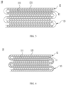
- FIG. 7 is a schematic cross-sectional view of still another electrode assembly 10 according to an embodiment of this application.
- the electrode assembly 10 according to this embodiment of this application is a winding structure and includes a first electrode plate 11, a second electrode plate 12, and a separator 13.
- the electrode assembly 10 includes one first electrode plate 11 and one second electrode plate 12, which are in a continuous strip structure.
- the separator 13 is provided in two, which are referred to as a first separator and a second separator respectively.
- the first electrode plate 11, the first separator, the second electrode plate 12, and the second separator are stacked sequentially and wound around a winding axis two or more times to form the electrode assembly 10, and the electrode assembly 10 is flat-shaped.
- a first body portion 111 of the first electrode plate 11 and a second body portion 121 of the second electrode plate 12 are stacked, and the first body portion 111 and the second body portion 121 are stacked in a direction perpendicular to the winding axis.
- the first body portion 111 includes a plurality of first flat segments and a plurality of first bending segments, the plurality of first flat segments are stacked, and the first bending segment is at least partially bent to be arc-shaped and is connected to the first flat segment.
- each of the first bending segments is connected to two first flat segments.
- the second body portion 121 includes a plurality of second flat segments and a plurality of second bending segments, the plurality of second flat segments are stacked in a stacking direction, and the second bending segment is at least partially bent to be arc-shaped and connected to the second flat segment.
- each of the second bending segments is connected to two of the second flat segments.
- the first flat segments and the second flat segments are stacked, and the first bending segments and the second bending segments are stacked.
- FIG. 8 is a schematic front view of an electrode assembly 10 according to an embodiment of this application;
- FIG. 9 is a schematic cross-sectional view of the electrode assembly 10 in FIG. 8 along line A-A;
- FIG. 10 is a schematic enlarged view of the electrode assembly 10 in FIG. 9 in block B; and
- FIG. 11 is a schematic enlarged view of the electrode assembly 10 in FIG. 9 in block C.
- an electrode assembly 10 includes at least one first electrode plate 11 and at least one second electrode plate 12.
- the electrode assembly 10 shown in the figures is winding structure, and the first electrode plate 11 and the second electrode plate 12 each are provided in one.
- the first electrode plate 11 includes a first body portion 111 and a first tab 112 protruding from the first body portion 111
- the second the electrode plate 12 includes a second body portion 121 and a second tab 122 protruding from the second body portion 121.
- the first body portion 111 and the second body portion 121 are stacked.
- the first body portion 111 has two end portions that are disposed opposite to each other in a first direction X
- the second body portion 121 has two end portions that are disposed opposite to each other in the first direction X.
- the two end portions of the first body portion 111 are referred to as a first end portion 111a and a third end portion 111b
- the two end portions of the second body portion 121 are referred to as a second end portion 121a and a fourth end portion 121b.
- the first body portion 111 and the second body portion 121 are stacked in a direction Y perpendicular to the first direction X.
- the second end portion 121a is an end of the second body portion 121 close to the first end portion 111a
- the fourth end portion 121b is an end of the second body portion 121 close to the third end portion 111b.
- the first tab 112 is connected to the first end portion 111a; and the second end portion 121a is closer to the first tab 112 in the first direction X than the fourth end portion 121b.
- the second tab 122 may be connected to the second end portion 121a, and in this case, the first tab 112 and the second tab 122 are located at a same end of the electrode assembly 10 in the first direction X.
- the second tab 122 may alternatively be connected to the fourth end portion 121b, and in this case, the first tab 112 and the second tab 122 are located at two ends of the electrode assembly 10 in the first direction X respectively.
- the first body portion 111 includes a first current collection zone 1111 and a first active material layer 1112, where the first active material layer 1112 is applied on a surface of the first current collection zone 1111.
- the first active material layer 1112 includes a first conductive agent, a first binder, and a first active material, where the first active material is used to intercalate and deintercalate metal ions. Materials for all segments of the first body portion 111 are determined according to a polarity of the first electrode plate 11.
- the first current collection zone 1111 may be made of aluminum, and the first active material may be lithium cobaltate, lithium iron phosphate, ternary lithium, lithium manganate, or the like; and under the condition that the first electrode plate 11 is a negative electrode plate, the first current collection zone 1111 may be made of copper, and the first active material may be carbon, silicon, or the like.
- the second body portion 121 includes a second current collection zone 1211 and a second active material layer 1212, where the second active material layer 1212 is applied on a surface of the second current collection zone 1211.
- the second active material layer 1212 includes a second conductive agent, a second binder, and a second active material, where the second active material is used to intercalate or deintercalate metal ions. Materials for all parts of the second body portion 121 are determined according to a polarity of the second electrode plate 12.
- the second current collection zone 1211 may be made of aluminum, and the second active material may be lithium cobaltate, lithium iron phosphate, ternary lithium, lithium manganate, or the like; and under the condition that the second electrode plate 12 is a negative electrode plate, the second current collection zone 1211 may be made of copper, and the second active material may be carbon, silicon, or the like.
- the first tab 112 is connected to the first current collection zone 1111.
- the first tab 112 may be integrally formed with the first current collection zone 1111, or the first tab 112 and the first current collection zone 1111 may be separately formed.
- the first tab 112 may be connected to the first current collection zone 1111 by using a method such as welding.
- the second tab 122 is connected to the second current collection zone 1211.
- the second tab 122 may be integrally formed with the second current collection zone 1211, or the second tab 122 and the second current collection zone 1211 may be separately formed.
- the second tab 122 may be connected to the second current collection zone 1211 by using a method such as welding.
- first tabs 112 are stacked together, and a plurality of second tabs 122 are stacked together.
- the first end portion 111a includes one end portion of the first current collection zone 1111 in the first direction X
- the third end portion 111b includes the other end portion of the first current collection zone 1111 in the first direction X.
- the second end portion 121a includes one end portion of the second current collection zone 1211 in the first direction X
- the fourth end portion 121b includes the other end portion of the second current collection zone 1211 in the first direction X.
- the inventors have found that during assembly and use of a battery cell 5, because the first tab 112 is relatively thin, the first tab 112 may be bent, which may result in contact of the first tab 112 and the second end portion 121a. In this case, the first tab 112 is and the second body portion 121 are connected, causing a risk of short circuits.
- the inventors have improved the structure of the electrode assembly 10 so as to reduce the risk of short circuits.
- the second electrode plate 12 further includes a second insulation portion 123 connected to the second body portion 121, where the second insulation portion 123 covers at least part of the second end portion 121a so as to separate the first tab 112 from the second end portion 121a when the first tab 112 is bent.
- the second insulation portion 123 is provided to reduce a risk of the first tab 112 contacting the second end portion 121a when the first tab 112 is bent, improving safety performance of the electrode assembly 10.
- the first electrode plate 11 and the electrode plate 12 usually need to be cut. After being formed through cutting, end portions of the first current collection zone 1111 and end portions of the second current collection zone 1211 will have burrs (it means that the first end portion 111a, the second end portion 121a, the third end portion 111b, and the fourth end portion 121b have burrs), making the burrs pierce the separator 13 and causing a risk of short circuits.
- the second insulation portion 123 can cover at least part of the second end portion 121a, thus reducing a risk of burrs piercing the separator 13 and improving safety performance.
- the inventors have further found that, when the first tab 112 is bent, a root of the first tab 112 close to the first body portion 111 may be inserted between the first body portion 111 and the second body portion 121, and in such case, the first tab 112 and the second body portion 121 are connected, causing the risk of short circuits.
- the inventors have improved the structure of the second electrode plate 12 so as to reduce the risk of short circuits.
- the second insulation portion 123 includes a second coverage zone 1231 and a second connection zone 1232 connected to the second coverage zone 1231, where the second coverage zone 1231 is disposed on a side of the second body portion 121 in the first direction X and covers at least part of the second end portion 121a, and the second connection zone 1232 is connected to the second body portion 121.
- the second connection zone 1232 is at least partially located between the first body portion 111 and the second body portion 121 so as to separate the second body portion 121 from the first tab 112 when the first tab 112 is inserted between the first body portion 111 and the second body portion 121.
- the second connection zone 1232 can reduce a risk of the first tab 112 contacting the second body portion 121 when the first tab 112 is inserted between the first body portion 111 and the second body portion 121, improving safety performance.
- the second connection zone 1232 is provided in two, which are disposed on two sides of the second body portion 121 in a stacking direction Y respectively.
- the second coverage zone 1231 and the two second connection zones 1232 form a U-shaped structure and cover part of the second body portion 121 close to the first tab 112.
- the two second connection zones 1232 can increase connection area between the second insulation portion 123 and the second body portion 121, enhancing connection strength between the second insulation portion 123 and the second body portion 121, and reducing a risk of the second insulation portion 123 coming off.
- the second insulation portion 123 is adhered to the second body portion 121.
- the second body portion 121 may be coated with insulation glue, and the insulation glue forms the second insulation portion 123 after curing.
- the second insulation portion 123 may be an insulation tape.
- thickness of the second insulation portion 123 is greater than thickness of the separator 13.
- the second insulation portion 123 has greater thickness and strength than the separator 13, and is difficult to be pierced by burrs on the second end portion 121a, thus reducing a risk of short circuits.
- a size of the second connection zone 1232 in the first direction X is L1.
- a smaller L1 indicates lower connection strength between the second insulation portion 123 and the second body portion 121 and a higher risk of the second insulation portion 123 coming off. Under the condition that the second insulation portion 123 is too small, the second insulation portion 123 has relatively high requirements for coating process.
- a larger L1 indicates larger space occupied by the second insulation portion 123 and lower energy density of the battery cell 5.
- the inventors have comprehensively considered the connection strength and energy density, and a value of L1 is set in a range of 0.3 mm to 6 mm. Optionally, the value of L1 ranges from 1 mm to 3 mm.
- the second insulation portion 123 indicates lower strength, making the burrs on the second end portion 121a pierce the second insulation portion 123 easier; and under the condition that the thickness of the second insulation portion 123 is too small, the burrs pierces the second insulation portion 123 pretty easily and good insulation effect is unable to be ensured.
- Greater thickness of the second insulation portion 123 indicates larger space occupied by the second insulation portion 123 and a larger gap between the first body portion 111 and the second body portion 121. Under the condition that the gap between the first body portion 111 and the second body portion 121 is too large, lithium precipitation is easy to occur. During a cycling process of the battery cell 5, the first body portion 111 and the second body portion 121 will press the second connection zone 1232.
- thickness of the second insulation portion 123 is set in a range of 0.005 mm to 0.2 mm.
- thickness of the second insulation portion 123 ranges from 0.02 mm to 0.1 mm.
- a size of the second body portion 121 in the first direction X is L2.
- a larger L2 makes the second body portion 121 swell more during the cycling of the battery cell 5, a greater force applied on the second insulation portion 123 if the second body portion 121 is deformed due to swelling, and a higher risk of separating the second body portion 121 from the second insulation portion 123; and a smaller L2 makes a higher ratio of L1 to L2, and greater percentage of energy loss caused by the second insulation portion 123.
- the ratio of L1 to L2 is set in a range of 0.5% to 6%. That means a ratio of a size of the second connection zone 1232 in the first direction X to a size of the second body portion 121 in the first direction X ranges from 0.5% to 6%.
- the second insulation portion 123 has a porous structure for metal ions to pass through.
- the metal ions are able to pass through the second insulation portion 123 to reduce resistance of the second insulation portion 123 to transport the metal ions, helping intercalate and deintercalate the metal ions.
- the first electrode plate 11 further includes a first insulation portion 113, where the first insulation portion 113 includes a first coverage zone 1131 and a first connection zone 1132 connected to the first coverage zone 1131, and the first coverage zone 1131 is disposed on a side of the first body portion 111 in the first direction X and covers at least part of the first end portion 111a.
- the first connection zone 1132 is at least partially located between the first body portion 111 and the second body portion 121 and is connected to the first body portion 111.
- the first insulation portion 113 can cover at least part of the first end portion 111a, thereby reducing a risk of burrs piercing the separator 13 and improving safety performance.
- first connection zones 1132 there are two first connection zones 1132, and the first coverage zone 1131 and the two first connection zones 1132 form a U-shaped structure. In some embodiments, materials and structures of the first insulation portion 113 and the second insulation portion 123 are same.
- the second tab 122 is connected to the second end portion 121a.
- the first coverage zone 1131 can separate the second tab 122 from the first end portion 111a when the second tab 122 is bent, reducing a risk of the second tab 122 contacting the first body portion 111 and improving safety performance of an electrode assembly 10.
- the first connection zone 1132 is provided to reduce a risk of the second tab 122 contacting the first body portion 111 when the second tab 122 is inserted between the first body portion 111 and the second body portion 121 and improve safety performance.
- the first electrode plate 11 further includes a third insulation portion 114, where the third insulation portion 114 is connected to the first body portion 111 and covers at least part of the third end portion 111b.
- the third insulation portion 114 can cover at least part of the third end portion 111b, thereby reducing a risk of burrs piercing the separator 13 and improving safety performance.
- the third insulation portion 114 includes a third coverage zone 1141 and a third connection zone 1142 connected to the third coverage zone 1141.
- the third coverage zone 1141 is disposed on a side of the first body portion 111 in the first direction X and covers at least part of the third end portion 111b.
- the third connection zone 1142 is at least partially located between the first body portion 111 and the second body portion 121 and is connected to the first body portion 111.
- the third insulation portion 114 is of a U-shaped structure and includes two third connection zones 1142, and the two third connection zones 1142 are located on two sides of the first body portion 111 respectively.
- the second electrode plate 12 further includes a fourth insulation portion 124, where the fourth insulation portion 124 is connected to the second body portion 121 and covers at least part of the fourth end portion 121b.
- the fourth insulation portion 124 can cover at least part of the fourth end portion 121b, thereby reducing a risk of burrs piercing the separator 13 and improving safety performance.
- the fourth insulation portion 124 includes a fourth coverage zone 1241 and a fourth connection zone 1242 connected to the fourth coverage zone 1241, where the fourth coverage zone 1241 is disposed on a side of the second body portion 121 in the first direction X and covers at least part of the fourth end portion 121b.
- the fourth connection zone 1242 is at least partially located between the first body portion 111 and the second body portion 121 and is connected to the second body portion 121.
- the fourth insulation portion 124 is of a U-shaped structure and includes two fourth connection zones 1242, and the two fourth connection zones 1242 are located on two sides of the second body portion 121 respectively.
- the first insulation portion 113, the third insulation portion 114, and the fourth insulation portion 124 each have a porous structure for metal ions to pass through.
- the first electrode plate 11 is a positive electrode plate
- the second electrode plate 12 is a negative electrode plate.
- metal ions deintercalated from the first active material layer 1112 need to be intercalated into the second active material layer 1212. If the second active material layer 1212 provides insufficient space for lithiation, a risk of lithium precipitation is easily caused.
- the first connection zone 1132 and the second connection zone 1232 partly block transport of metal ions, therefore, the metal ions are mainly deintercalated from a portion of the first active material layer 1112 that is not covered by the first connection zone 1132, and then are intercalated into a portion of the second active material layer 1212 that is not covered by the second connection zone 1232.
- an edge of the second connection zone 1232 farther away from the second coverage zone 1231 does not exceed an edge of the first connection zone 1132 farther away from the first coverage zone 1131.
- the portion of the second active material layer 1212 that is not covered by the second connection zone 1232 can cover the portion of the first active material layer 1112 that is not covered by the first connection zone 1132, providing more space for intercalating metal ions and reducing a risk of lithium precipitation.
- a gap between the edge of the second connection zone 1232 farther away from the second coverage zone 1231 and the edge of the first connection zone 1132 farther away from the first coverage zone 1131 is greater than 0.05 mm, so that the portion of the second active material layer 1212 that is not covered by the second connection zone 1232 has a larger area for intercalating more metal ions, reducing the risk of lithium precipitation.
- the first body portion 111 further includes a first protective layer 1113, where the first protective layer 1113 is applied on a surface of the first current collection zone 1111 and is connected to the first active material layer 1112, and the first protective layer 1113 is located on a side of the first active material layer 1112 in the first direction X and close to the first tab 112.
- the first protective layer 1113 is an insulation layer.
- the first protective layer 1113 includes a binder and an insulation material, and the insulation material includes at least one of aluminum oxide and aluminum hydroxide oxide.
- a root of the first tab 112 close to the first body portion 111 is provided with a second protective layer (not shown in the figure), and the second protective layer can improve insulation of the root of the first tab 112 close to the first body portion 111.
- the first protective layer 1113 and the second protective layer are integrally formed.
- the first tab 112 is made by using cutting process.
- the first protective layer 1113 and the second protective layer can reduce burrs at a cutting position in the cutting process of the first tab 112.
- the first connection zone 1132 is fastened to the first protective layer 1113, and in a direction farther away from the first tab 112 and parallel to the first direction X, an edge of the first connection zone 1132 farther away from the first coverage zone 1131 does not exceed the first protective layer 1113.
- the first connection zone 1132 does not cover the first active material layer 1112, and the first connection zone 1132 does not block deintercalating metal ions from the first active material layer 1112, improving cycling performance of the electrode assembly 10.
- an edge of the fourth connection zone 1242 farther away from the fourth coverage zone 1241 does not exceed an edge of the third connection zone 1142 farther away from the third coverage zone 1141.
- a gap between the edge of the fourth connection zone 1242 farther away from the fourth coverage zone 1241 and the edge of the third connection zone 1142 farther away from the third coverage zone 1141 is greater than 0.05 mm.
- FIG. 12 is a schematic structural diagram of a first electrode plate 11 in an unwound state according to an embodiment of this application; and FIG. 13 is a schematic cross-sectional view of the first electrode plate 11 in FIG. 12 along line D-D.
- the first electrode plate 11 in an unwound state, extends along a length direction of the first electrode plate 11 itself.
- there may be a plurality of first insulation portions 113 where the plurality of first insulation portions 113 and a plurality of first tabs 112 are arranged alternatively in a length direction of the first electrode plate 11.
- Each first insulation portion 113 covers part of the first end portion 111a.
- FIG. 14 is a schematic structural diagram of a second electrode plate 12 in an unwound state according to an embodiment of this application; and FIG. 15 is a schematic cross-sectional view of the second electrode plate 12 in FIG. 14 along line E-E.
- the second electrode plate 12 in an unwound state, extends in a length direction of the second electrode plate 12 itself.
- Each second insulation portion 123 covers part of the second end portion 121a.
- FIG. 16 is a schematic front view of another electrode assembly 10 according to an embodiment of this application; and FIG. 17 is a schematic cross-sectional view of the electrode assembly 10 in FIG. 16 along line F-F.
- a second tab 122 is connected to a fourth end portion 121b.
- a third insulation portion 114 can separate the second tab 122 and a third end portion 111b when the second tab 122 is bent, reducing a risk of the second tab 122 contacting the first body portion 111 and improving safety performance of the electrode assembly 10.
- the third insulation portion 114 can also reduce the risk of the second tab 122 contacting the first body portion 111, improving safety performance.
Landscapes
- Chemical & Material Sciences (AREA)
- Chemical Kinetics & Catalysis (AREA)
- Electrochemistry (AREA)
- General Chemical & Material Sciences (AREA)
- Engineering & Computer Science (AREA)
- Manufacturing & Machinery (AREA)
- Connection Of Batteries Or Terminals (AREA)
- Cell Separators (AREA)
- Secondary Cells (AREA)
- Battery Electrode And Active Subsutance (AREA)
- Aviation & Aerospace Engineering (AREA)
Claims (12)
- Elektrodenanordnung (10), umfassend:mindestens eine erste Elektrodenplatte (11), die einen ersten Körperabschnitt (111) und eine erste Nase (112) umfasst, wobei der erste Körperabschnitt (111) einen ersten Endabschnitt (111a) in einer ersten Richtung (X) aufweist und die erste Nase (112) mit dem ersten Endabschnitt (111a) verbunden ist; undmindestens eine zweite Elektrodenplatte (12), deren Polarität der der ersten Elektrodenplatte (11) entgegengesetzt ist, wobei die zweite Elektrodenplatte (12) einen zweiten Körperabschnitt (121) und einen mit dem zweiten Körperabschnitt (121) verbundenen zweiten Isolationsabschnitt (123) umfasst, wobei der erste Körperabschnitt (111) und der zweite Körperabschnitt (121) in eine Richtung (Y) senkrecht zu der ersten Richtung (X) gestapelt sind, der zweite Körperabschnitt (121) einen zweiten Endabschnitt (121a) nahe an der ersten Nase (112) in der ersten Richtung (X) aufweist und der zweite Isolationsabschnitt (123) mindestens einen Teil des zweiten Endabschnitts (121a) so bedeckt, dass die erste Nase (112) von dem zweiten Endabschnitt (121a) getrennt ist, wenn die erste Nase (112) gebogen ist;wobei der zweite Isolationsabschnitt (123) eine zweite Abdeckzone (1231) und eine mit der zweiten Abdeckzone (1231) verbundene zweite Verbindungszone (1232) umfasst, die zweite Abdeckzone (1231) auf einer Seite des zweiten Körperabschnitts (121) in der ersten Richtung (X) angeordnet ist und mindestens einen Teil des zweiten Endabschnitts (121a) bedeckt und die zweite Verbindungszone (1232) mit dem zweiten Körperabschnitt (121) verbunden ist; unddie zweite Verbindungszone (1232) sich mindestens teilweise zwischen dem ersten Körperabschnitt (111) und dem zweiten Körperabschnitt (121) befindet, um den zweiten Körperabschnitt (121) von der ersten Nase (112) zu trennen, wenn die erste Nase (112) zwischen den ersten Körperabschnitt (111) und den zweiten Körperabschnitt (121) eingefügt wird; undwobei die erste Elektrodenplatte (11) weiter einen ersten Isolationsabschnitt (113) umfasst, wobei der erste Isolationsabschnitt (113) eine erste Abdeckzone (1131) und eine mit der ersten Abdeckzone (1131) verbundene erste Verbindungszone (1132) umfasst und die erste Abdeckzone (1131) auf einer Seite des ersten Körperabschnitts (111) in der ersten Richtung (X) angeordnet ist und mindestens einen Teil des ersten Endabschnitts (111a) bedeckt; unddie erste Verbindungszone (1132) sich mindestens teilweise zwischen dem ersten Körperabschnitt (111) und dem zweiten Körperabschnitt (121) befindet und mit dem ersten Körperabschnitt (111) verbunden ist; undwobei die erste Elektrodenplatte (11) eine positive Elektrodenplatte ist und die zweite Elektrodenplatte (12) eine negative Elektrodenplatte ist;und in einer Richtung weiter weg von der ersten Nase (112) und parallel zu der ersten Richtung (X) ein Rand der zweiten Verbindungszone (1232) weiter weg von der zweiten Abdeckzone (1231) einen Rand der ersten Verbindungszone (1132) weiter weg von der ersten Abdeckzone (1131) nicht übersteigt.
- Elektrodenanordnung (10) nach Anspruch 1, wobei die zweite Verbindungszone (1232) in zwei Teilen vorgesehen ist, die jeweils in einer Stapelrichtung (Y) auf zwei Seiten des zweiten Körperabschnitts (121) angeordnet sind.
- Elektrodenanordnung (10) nach Anspruch 1 oder 2, wobei ein Verhältnis aus einer Größe der zweiten Verbindungszone (1232) in der ersten Richtung (X) zu einer Größe des zweiten Körperabschnitts (121) in der ersten Richtung (X) im Bereich von 0,5 % bis 6 % liegt.
- Elektrodenanordnung (10) nach Anspruch 1, wobei in der Richtung weiter weg von der ersten Nase (112) und parallel zu der ersten Richtung (X) ein Spalt zwischen dem Rand der zweiten Verbindungszone (1232) weiter weg von der zweiten Abdeckzone (1231) und dem Rand der ersten Verbindungszone (1132) weiter weg von der ersten Abdeckzone (1131) größer ist als 0,05 mm.
- Elektrodenanordnung (10) nach Anspruch 1 oder 4, wobeider erste Körperabschnitt (111) eine erste Stromsammelzone (1111), eine erste aktive Materialschicht (1112) und eine erste Schutzschicht (1113) umfasst, die erste aktive Materialschicht (1112) auf einer Oberfläche der ersten Stromsammelzone (1111) aufgebracht ist und die erste Schutzschicht (1113) auf einer Oberfläche der ersten Stromsammelzone (1111) aufgebracht und mit der ersten aktiven Materialschicht (1112) verbunden ist;die erste Schutzschicht (1113) sich auf einer Seite der ersten aktiven Materialschicht (1112) in der ersten Richtung (X) und nahe an der ersten Nase (112) befindet; unddie erste Verbindungszone (1132) an der ersten Schutzschicht (1113) und in einer Richtung weiter weg von der ersten Nase (112) und parallel zu der ersten Richtung (X) fixiert ist, ein Rand der ersten Verbindungszone (1132) weg von der ersten Abdeckzone (1131) die erste Schutzschicht (1113) nicht überragt.
- Elektrodenanordnung (10) nach einem der Ansprüche 1 bis 5, wobeider erste Körperabschnitt (111) einen dritten Endabschnitt (111b) in der ersten Richtung (X) weiter weg von dem ersten Endabschnitt (111a) aufweist und der zweite Körperabschnitt (121) einen vierten Endabschnitt (121b) in der ersten Richtung (X) weiter weg von dem zweiten Endabschnitt (121a) aufweist; unddie zweite Elektrodenplatte (12) weiter eine zweite Nase (122) umfasst, wobei die zweite Nase (122) mit dem zweiten Endabschnitt (121a) oder dem vierten Endabschnitt (121b) verbunden ist.
- Elektrodenanordnung (10) nach Anspruch 6, wobeidie erste Elektrodenplatte (11) weiter einen dritten Isolationsabschnitt (114) umfasst, wobei der dritte Isolationsabschnitt (114) mit dem ersten Körperabschnitt (111) verbunden ist und mindestens einen Teil des dritten Endabschnitts (111b) bedeckt; und/oderdie zweite Elektrodenplatte (12) weiter einen vierten Isolationsabschnitt (124) umfasst, wobei der vierte Isolationsabschnitt (124) mit dem zweiten Körperabschnitt (121) verbunden ist und mindestens einen Teil des vierten Endabschnitts (121b) bedeckt.
- Elektrodenanordnung (10) nach einem der Ansprüche 1 bis 7, wobei der zweite Isolationsabschnitt (123) eine poröse Struktur für den Durchtritt von Metallionen aufweist.
- Elektrodenanordnung (10) nach einem der Ansprüche 1 bis 8, wobei die Elektrodenanordnung (10) weiter einen Separator (13) umfasst, der konfiguriert ist zum Separieren der ersten Elektrodenplatte (11) von der zweiten Elektrodenplatte (12);
und eine Dicke des zweiten Isolationsabschnitts (123) größer ist als eine Dicke des Separators (13). - Batteriezelle (5), umfassend:ein Gehäuse (20) mit einem Aufnahmehohlraum und einer Öffnung;mindestens eine Elektrodenanordnung (10) nach einem der Ansprüche 1 bis 9, aufgenommen in dem Aufnahmehohlraum; undeine Abdeckplatte, die konfiguriert ist zum Schließen der Öffnung des Gehäuses (20).
- Batterie (2), umfassend:einen kastenförmigen Körper; undmindestens eine Batteriezelle (5) nach Anspruch 10, wobei die Batteriezelle (5) in dem kastenförmigen Körper untergebracht ist.
- Elektrische Vorrichtung, wobei die elektrische Vorrichtung konfiguriert ist zum Empfangen von durch die Batterie (2) nach Anspruch 11 geliefertem Strom.
Priority Applications (1)
| Application Number | Priority Date | Filing Date | Title |
|---|---|---|---|
| EP25150191.2A EP4550565A3 (de) | 2020-12-31 | 2021-10-29 | Elektrodenanordnung, batteriezelle, batteriestromverbrauchsvorrichtung |
Applications Claiming Priority (2)
| Application Number | Priority Date | Filing Date | Title |
|---|---|---|---|
| CN202023344172.0U CN214254666U (zh) | 2020-12-31 | 2020-12-31 | 电极组件、电池单体、电池以及用电装置 |
| PCT/CN2021/127714 WO2022142693A1 (zh) | 2020-12-31 | 2021-10-29 | 电极组件、电池单体、电池以及用电装置 |
Related Child Applications (2)
| Application Number | Title | Priority Date | Filing Date |
|---|---|---|---|
| EP25150191.2A Division EP4550565A3 (de) | 2020-12-31 | 2021-10-29 | Elektrodenanordnung, batteriezelle, batteriestromverbrauchsvorrichtung |
| EP25150191.2A Division-Into EP4550565A3 (de) | 2020-12-31 | 2021-10-29 | Elektrodenanordnung, batteriezelle, batteriestromverbrauchsvorrichtung |
Publications (3)
| Publication Number | Publication Date |
|---|---|
| EP4131631A1 EP4131631A1 (de) | 2023-02-08 |
| EP4131631A4 EP4131631A4 (de) | 2023-12-20 |
| EP4131631B1 true EP4131631B1 (de) | 2025-02-12 |
Family
ID=77723558
Family Applications (2)
| Application Number | Title | Priority Date | Filing Date |
|---|---|---|---|
| EP25150191.2A Pending EP4550565A3 (de) | 2020-12-31 | 2021-10-29 | Elektrodenanordnung, batteriezelle, batteriestromverbrauchsvorrichtung |
| EP21913437.6A Active EP4131631B1 (de) | 2020-12-31 | 2021-10-29 | Elektrodenanordnung, batteriezelle, batterie und stromverbrauchende vorrichtung |
Family Applications Before (1)
| Application Number | Title | Priority Date | Filing Date |
|---|---|---|---|
| EP25150191.2A Pending EP4550565A3 (de) | 2020-12-31 | 2021-10-29 | Elektrodenanordnung, batteriezelle, batteriestromverbrauchsvorrichtung |
Country Status (7)
| Country | Link |
|---|---|
| US (1) | US12463309B2 (de) |
| EP (2) | EP4550565A3 (de) |
| JP (1) | JP7497461B2 (de) |
| KR (1) | KR102771134B1 (de) |
| CN (1) | CN214254666U (de) |
| HU (1) | HUE071245T2 (de) |
| WO (1) | WO2022142693A1 (de) |
Families Citing this family (16)
| Publication number | Priority date | Publication date | Assignee | Title |
|---|---|---|---|---|
| CN214254666U (zh) | 2020-12-31 | 2021-09-21 | 宁德时代新能源科技股份有限公司 | 电极组件、电池单体、电池以及用电装置 |
| CN115863931B (zh) * | 2021-09-27 | 2025-02-25 | 宁德时代新能源科技股份有限公司 | 极片、电芯组件及制备方法、电池单体、电池及用电装置 |
| CN216750238U (zh) * | 2021-11-25 | 2022-06-14 | 宁德时代新能源科技股份有限公司 | 正极极片和电池 |
| CN116941119A (zh) * | 2022-01-05 | 2023-10-24 | 宁德时代新能源科技股份有限公司 | 电极组件及其制备方法、电池单体、电池及用电设备 |
| EP4468445A4 (de) * | 2022-01-19 | 2025-06-11 | LG Energy Solution, Ltd. | Elektrodenanordnung mit kurzschlussverhinderungsstruktur |
| CN114122327B (zh) * | 2022-01-29 | 2022-07-15 | 宁德时代新能源科技股份有限公司 | 一种极片及具备其的二次电池 |
| CN115911776B (zh) * | 2022-04-15 | 2025-08-05 | 宁德时代新能源科技股份有限公司 | 叠片式电极组件、电池单体、电池及用电装置 |
| WO2023225903A1 (zh) * | 2022-05-25 | 2023-11-30 | 宁德时代新能源科技股份有限公司 | 电池单体、电池以及用电装置 |
| CN118043988A (zh) * | 2022-06-28 | 2024-05-14 | 宁德时代新能源科技股份有限公司 | 极片、电极组件、电池单体、电池和用电设备 |
| EP4567916A4 (de) * | 2022-08-05 | 2025-10-29 | Contemporary Amperex Technology Hong Kong Ltd | Batteriezelle, batterie und elektrische vorrichtung |
| CN115275092B (zh) * | 2022-09-22 | 2023-07-07 | 江苏时代新能源科技有限公司 | 电极组件、电池单体、电池及用电设备 |
| CN118645700A (zh) * | 2023-03-13 | 2024-09-13 | 宁德时代新能源科技股份有限公司 | 电池单体、制造电池单体的方法、电池和用电装置 |
| CN119009390A (zh) * | 2023-05-22 | 2024-11-22 | 宁德时代新能源科技股份有限公司 | 极片及其制备方法、电池单体、电池、用电装置 |
| CN120080049A (zh) * | 2023-11-30 | 2025-06-03 | 宁德时代新能源科技股份有限公司 | 电池加工设备和加工方法 |
| WO2025152163A1 (zh) * | 2024-01-19 | 2025-07-24 | 宁德时代新能源科技股份有限公司 | 电极组件、电池单体、电池以及用电装置 |
| CN118198677A (zh) * | 2024-02-04 | 2024-06-14 | 宁德时代新能源科技股份有限公司 | 电极组件及其制造方法、电池单体、电池和用电装置 |
Family Cites Families (21)
| Publication number | Priority date | Publication date | Assignee | Title |
|---|---|---|---|---|
| JP4366783B2 (ja) | 1998-11-16 | 2009-11-18 | 株式会社デンソー | 積層型電池及びその電極の製造方法 |
| CA2394410A1 (en) * | 2001-07-19 | 2003-01-19 | Wilson Greatbatch Technologies, Inc. | Insulative component for an electrochemical cell |
| JP4031635B2 (ja) | 2001-11-08 | 2008-01-09 | Tdk株式会社 | 電気化学デバイス |
| KR100449757B1 (ko) * | 2001-11-23 | 2004-09-22 | 삼성에스디아이 주식회사 | 전지부와 이를 채용한 이차전지 |
| JP4201619B2 (ja) | 2003-02-26 | 2008-12-24 | 三洋電機株式会社 | 非水電解質二次電池、及びそれに使用する電極の製造方法 |
| KR101495294B1 (ko) * | 2011-11-08 | 2015-02-25 | 주식회사 엘지화학 | 전극 탭 보호 장치 및 이를 포함하는 이차 전지 |
| WO2015129320A1 (ja) * | 2014-02-28 | 2015-09-03 | Necエナジーデバイス株式会社 | 二次電池用電極および二次電池とそれらの製造方法 |
| JPWO2016067706A1 (ja) * | 2014-10-27 | 2017-08-31 | Necエナジーデバイス株式会社 | 二次電池用電極の製造方法、二次電池用電極、および二次電池 |
| KR20160059748A (ko) * | 2014-11-19 | 2016-05-27 | 삼성에스디아이 주식회사 | 전극 조립체 및 이를 포함하는 배터리 팩 |
| TW201729451A (zh) | 2015-09-30 | 2017-08-16 | 積水化學工業股份有限公司 | 鋰離子二次電池之電極部、鋰離子二次電池及鋰離子二次電池之製造方法 |
| US10115997B2 (en) * | 2016-05-12 | 2018-10-30 | Bosch Battery Systems Llc | Prismatic electrochemical cell |
| CN110178247A (zh) * | 2016-11-04 | 2019-08-27 | 株式会社杰士汤浅国际 | 蓄电元件用电极、蓄电元件和蓄电元件用电极的制造方法 |
| CN110168777A (zh) * | 2017-02-27 | 2019-08-23 | 松下知识产权经营株式会社 | 非水电解质二次电池 |
| JP6961398B2 (ja) * | 2017-06-14 | 2021-11-05 | 株式会社エンビジョンAescジャパン | リチウムイオン二次電池素子およびリチウムイオン二次電池 |
| JP7182861B2 (ja) | 2017-10-25 | 2022-12-05 | 株式会社東芝 | 電池及びその製造方法 |
| JP7545898B2 (ja) | 2018-12-19 | 2024-09-05 | 三洋電機株式会社 | 二次電池用の電極板及びそれを用いた二次電池 |
| CN210110993U (zh) | 2019-07-16 | 2020-02-21 | 江苏塔菲尔新能源科技股份有限公司 | 锂离子电池的裸电芯 |
| CN111326699B (zh) | 2019-08-14 | 2021-11-09 | 宁德时代新能源科技股份有限公司 | 二次电池 |
| CN210535760U (zh) * | 2019-08-14 | 2020-05-15 | 宁德时代新能源科技股份有限公司 | 电极组件和二次电池 |
| KR102232115B1 (ko) | 2020-06-15 | 2021-03-25 | 주식회사 엘지화학 | 버스바를 적용한 배터리 셀 |
| CN214254666U (zh) * | 2020-12-31 | 2021-09-21 | 宁德时代新能源科技股份有限公司 | 电极组件、电池单体、电池以及用电装置 |
-
2020
- 2020-12-31 CN CN202023344172.0U patent/CN214254666U/zh active Active
-
2021
- 2021-10-29 JP JP2022567035A patent/JP7497461B2/ja active Active
- 2021-10-29 EP EP25150191.2A patent/EP4550565A3/de active Pending
- 2021-10-29 KR KR1020227038354A patent/KR102771134B1/ko active Active
- 2021-10-29 EP EP21913437.6A patent/EP4131631B1/de active Active
- 2021-10-29 HU HUE21913437A patent/HUE071245T2/hu unknown
- 2021-10-29 WO PCT/CN2021/127714 patent/WO2022142693A1/zh not_active Ceased
-
2023
- 2023-01-26 US US18/159,684 patent/US12463309B2/en active Active
Also Published As
| Publication number | Publication date |
|---|---|
| KR20220162780A (ko) | 2022-12-08 |
| HUE071245T2 (hu) | 2025-08-28 |
| EP4550565A2 (de) | 2025-05-07 |
| WO2022142693A1 (zh) | 2022-07-07 |
| EP4550565A3 (de) | 2025-07-09 |
| EP4131631A1 (de) | 2023-02-08 |
| US12463309B2 (en) | 2025-11-04 |
| JP2023527676A (ja) | 2023-06-30 |
| US20230170592A1 (en) | 2023-06-01 |
| KR102771134B1 (ko) | 2025-02-26 |
| CN214254666U (zh) | 2021-09-21 |
| JP7497461B2 (ja) | 2024-06-10 |
| EP4131631A4 (de) | 2023-12-20 |
Similar Documents
| Publication | Publication Date | Title |
|---|---|---|
| EP4131631B1 (de) | Elektrodenanordnung, batteriezelle, batterie und stromverbrauchende vorrichtung | |
| US20250015426A1 (en) | Housing, battery cell, battery, and power consuming device | |
| US12412933B2 (en) | Electrode assembly, battery cell, battery, manufacturing method and device for electrode assembly | |
| JP2023517924A (ja) | 電極組立体、電池セル、電池及び電力消費装置 | |
| US12542334B2 (en) | Electrode assembly, battery cell, battery and electrical device | |
| US12407029B2 (en) | Winding type electrode assembly, battery cell, battery and power consumption device | |
| US20240055646A1 (en) | Wound electrode assembly, battery cell, battery, and electrical device | |
| CN221508426U (zh) | 电极组件、电池单体、电池以及用电装置 | |
| US12506155B2 (en) | Electrode assembly, battery cell, battery, and method and device for manufacturing electrode assembly | |
| US20230369728A1 (en) | Electrode assembly, method and system for manufacturing same, battery cell, battery, and electric apparatus | |
| CN215299297U (zh) | 电极组件、电池单体、电池以及用电装置 | |
| US20240313359A1 (en) | Separator of electrode assembly, and method and device for preparing separator of electrode assembly | |
| CN221466696U (zh) | 电池的箱体、电池、用电设备和储能设备 | |
| EP4060783A1 (de) | Elektrodenanordnung, batteriezelle, batterie, herstellungsverfahren und vorrichtung für eine elektrodenanordnung | |
| CN220774658U (zh) | 连接件、电池模组、电池、用电设备和储能设备 | |
| US20250192398A1 (en) | Electrode assembly, battery cell, battery, and electrical device | |
| CN222785321U (zh) | 一种电芯、电池和用电装置 | |
| US20240170730A1 (en) | Electrode Assembly, Battery Cell, Battery and Electrical Apparatus | |
| US20230246199A1 (en) | Battery plate, electrode assembly, battery cell, battery and power consuming device | |
| WO2024077557A1 (zh) | 电池单体、电池及用电设备 | |
| WO2023216254A1 (zh) | 电极组件、电池单体、电池及用电设备 |
Legal Events
| Date | Code | Title | Description |
|---|---|---|---|
| STAA | Information on the status of an ep patent application or granted ep patent |
Free format text: STATUS: THE INTERNATIONAL PUBLICATION HAS BEEN MADE |
|
| PUAI | Public reference made under article 153(3) epc to a published international application that has entered the european phase |
Free format text: ORIGINAL CODE: 0009012 |
|
| STAA | Information on the status of an ep patent application or granted ep patent |
Free format text: STATUS: REQUEST FOR EXAMINATION WAS MADE |
|
| 17P | Request for examination filed |
Effective date: 20221118 |
|
| AK | Designated contracting states |
Kind code of ref document: A1 Designated state(s): AL AT BE BG CH CY CZ DE DK EE ES FI FR GB GR HR HU IE IS IT LI LT LU LV MC MK MT NL NO PL PT RO RS SE SI SK SM TR |
|
| A4 | Supplementary search report drawn up and despatched |
Effective date: 20231120 |
|
| RIC1 | Information provided on ipc code assigned before grant |
Ipc: H01M 50/595 20210101ALI20231114BHEP Ipc: H01M 10/42 20060101ALI20231114BHEP Ipc: H01M 10/0587 20100101ALI20231114BHEP Ipc: H01M 10/0583 20100101ALI20231114BHEP Ipc: H01M 10/04 20060101ALI20231114BHEP Ipc: H01M 50/586 20210101ALI20231114BHEP Ipc: H01M 50/531 20210101AFI20231114BHEP |
|
| DAV | Request for validation of the european patent (deleted) | ||
| DAX | Request for extension of the european patent (deleted) | ||
| GRAP | Despatch of communication of intention to grant a patent |
Free format text: ORIGINAL CODE: EPIDOSNIGR1 |
|
| STAA | Information on the status of an ep patent application or granted ep patent |
Free format text: STATUS: GRANT OF PATENT IS INTENDED |
|
| RAP1 | Party data changed (applicant data changed or rights of an application transferred) |
Owner name: CONTEMPORARY AMPEREX TECHNOLOGY(HONG KONG) LIMITED |
|
| INTG | Intention to grant announced |
Effective date: 20240911 |
|
| GRAS | Grant fee paid |
Free format text: ORIGINAL CODE: EPIDOSNIGR3 |
|
| GRAA | (expected) grant |
Free format text: ORIGINAL CODE: 0009210 |
|
| STAA | Information on the status of an ep patent application or granted ep patent |
Free format text: STATUS: THE PATENT HAS BEEN GRANTED |
|
| AK | Designated contracting states |
Kind code of ref document: B1 Designated state(s): AL AT BE BG CH CY CZ DE DK EE ES FI FR GB GR HR HU IE IS IT LI LT LU LV MC MK MT NL NO PL PT RO RS SE SI SK SM TR |
|
| REG | Reference to a national code |
Ref country code: GB Ref legal event code: FG4D |
|
| REG | Reference to a national code |
Ref country code: CH Ref legal event code: EP |
|
| P01 | Opt-out of the competence of the unified patent court (upc) registered |
Free format text: CASE NUMBER: APP_1299/2025 Effective date: 20250109 |
|
| REG | Reference to a national code |
Ref country code: DE Ref legal event code: R096 Ref document number: 602021026201 Country of ref document: DE |
|
| REG | Reference to a national code |
Ref country code: IE Ref legal event code: FG4D |
|
| REG | Reference to a national code |
Ref country code: NL Ref legal event code: FP |
|
| PG25 | Lapsed in a contracting state [announced via postgrant information from national office to epo] |
Ref country code: RS Free format text: LAPSE BECAUSE OF FAILURE TO SUBMIT A TRANSLATION OF THE DESCRIPTION OR TO PAY THE FEE WITHIN THE PRESCRIBED TIME-LIMIT Effective date: 20250512 |
|
| PG25 | Lapsed in a contracting state [announced via postgrant information from national office to epo] |
Ref country code: FI Free format text: LAPSE BECAUSE OF FAILURE TO SUBMIT A TRANSLATION OF THE DESCRIPTION OR TO PAY THE FEE WITHIN THE PRESCRIBED TIME-LIMIT Effective date: 20250212 |
|
| PG25 | Lapsed in a contracting state [announced via postgrant information from national office to epo] |
Ref country code: PL Free format text: LAPSE BECAUSE OF FAILURE TO SUBMIT A TRANSLATION OF THE DESCRIPTION OR TO PAY THE FEE WITHIN THE PRESCRIBED TIME-LIMIT Effective date: 20250212 |
|
| PG25 | Lapsed in a contracting state [announced via postgrant information from national office to epo] |
Ref country code: ES Free format text: LAPSE BECAUSE OF FAILURE TO SUBMIT A TRANSLATION OF THE DESCRIPTION OR TO PAY THE FEE WITHIN THE PRESCRIBED TIME-LIMIT Effective date: 20250212 |
|
| REG | Reference to a national code |
Ref country code: LT Ref legal event code: MG9D |
|
| PG25 | Lapsed in a contracting state [announced via postgrant information from national office to epo] |
Ref country code: IS Free format text: LAPSE BECAUSE OF FAILURE TO SUBMIT A TRANSLATION OF THE DESCRIPTION OR TO PAY THE FEE WITHIN THE PRESCRIBED TIME-LIMIT Effective date: 20250612 |
|
| PG25 | Lapsed in a contracting state [announced via postgrant information from national office to epo] |
Ref country code: HR Free format text: LAPSE BECAUSE OF FAILURE TO SUBMIT A TRANSLATION OF THE DESCRIPTION OR TO PAY THE FEE WITHIN THE PRESCRIBED TIME-LIMIT Effective date: 20250212 |
|
| PG25 | Lapsed in a contracting state [announced via postgrant information from national office to epo] |
Ref country code: LV Free format text: LAPSE BECAUSE OF FAILURE TO SUBMIT A TRANSLATION OF THE DESCRIPTION OR TO PAY THE FEE WITHIN THE PRESCRIBED TIME-LIMIT Effective date: 20250212 Ref country code: PT Free format text: LAPSE BECAUSE OF FAILURE TO SUBMIT A TRANSLATION OF THE DESCRIPTION OR TO PAY THE FEE WITHIN THE PRESCRIBED TIME-LIMIT Effective date: 20250612 |
|
| PG25 | Lapsed in a contracting state [announced via postgrant information from national office to epo] |
Ref country code: GR Free format text: LAPSE BECAUSE OF FAILURE TO SUBMIT A TRANSLATION OF THE DESCRIPTION OR TO PAY THE FEE WITHIN THE PRESCRIBED TIME-LIMIT Effective date: 20250513 Ref country code: BG Free format text: LAPSE BECAUSE OF FAILURE TO SUBMIT A TRANSLATION OF THE DESCRIPTION OR TO PAY THE FEE WITHIN THE PRESCRIBED TIME-LIMIT Effective date: 20250212 |
|
| REG | Reference to a national code |
Ref country code: AT Ref legal event code: MK05 Ref document number: 1767008 Country of ref document: AT Kind code of ref document: T Effective date: 20250212 |
|
| REG | Reference to a national code |
Ref country code: HU Ref legal event code: AG4A Ref document number: E071245 Country of ref document: HU |
|
| PG25 | Lapsed in a contracting state [announced via postgrant information from national office to epo] |
Ref country code: SE Free format text: LAPSE BECAUSE OF FAILURE TO SUBMIT A TRANSLATION OF THE DESCRIPTION OR TO PAY THE FEE WITHIN THE PRESCRIBED TIME-LIMIT Effective date: 20250212 |
|
| PG25 | Lapsed in a contracting state [announced via postgrant information from national office to epo] |
Ref country code: SM Free format text: LAPSE BECAUSE OF FAILURE TO SUBMIT A TRANSLATION OF THE DESCRIPTION OR TO PAY THE FEE WITHIN THE PRESCRIBED TIME-LIMIT Effective date: 20250212 |
|
| PG25 | Lapsed in a contracting state [announced via postgrant information from national office to epo] |
Ref country code: DK Free format text: LAPSE BECAUSE OF FAILURE TO SUBMIT A TRANSLATION OF THE DESCRIPTION OR TO PAY THE FEE WITHIN THE PRESCRIBED TIME-LIMIT Effective date: 20250212 |
|
| PG25 | Lapsed in a contracting state [announced via postgrant information from national office to epo] |
Ref country code: IT Free format text: LAPSE BECAUSE OF FAILURE TO SUBMIT A TRANSLATION OF THE DESCRIPTION OR TO PAY THE FEE WITHIN THE PRESCRIBED TIME-LIMIT Effective date: 20250212 |
|
| PG25 | Lapsed in a contracting state [announced via postgrant information from national office to epo] |
Ref country code: AT Free format text: LAPSE BECAUSE OF FAILURE TO SUBMIT A TRANSLATION OF THE DESCRIPTION OR TO PAY THE FEE WITHIN THE PRESCRIBED TIME-LIMIT Effective date: 20250212 |
|
| PG25 | Lapsed in a contracting state [announced via postgrant information from national office to epo] |
Ref country code: CZ Free format text: LAPSE BECAUSE OF FAILURE TO SUBMIT A TRANSLATION OF THE DESCRIPTION OR TO PAY THE FEE WITHIN THE PRESCRIBED TIME-LIMIT Effective date: 20250212 Ref country code: EE Free format text: LAPSE BECAUSE OF FAILURE TO SUBMIT A TRANSLATION OF THE DESCRIPTION OR TO PAY THE FEE WITHIN THE PRESCRIBED TIME-LIMIT Effective date: 20250212 |
|
| PG25 | Lapsed in a contracting state [announced via postgrant information from national office to epo] |
Ref country code: RO Free format text: LAPSE BECAUSE OF FAILURE TO SUBMIT A TRANSLATION OF THE DESCRIPTION OR TO PAY THE FEE WITHIN THE PRESCRIBED TIME-LIMIT Effective date: 20250212 |
|
| PG25 | Lapsed in a contracting state [announced via postgrant information from national office to epo] |
Ref country code: SK Free format text: LAPSE BECAUSE OF FAILURE TO SUBMIT A TRANSLATION OF THE DESCRIPTION OR TO PAY THE FEE WITHIN THE PRESCRIBED TIME-LIMIT Effective date: 20250212 |
|
| PGFP | Annual fee paid to national office [announced via postgrant information from national office to epo] |
Ref country code: HU Payment date: 20251007 Year of fee payment: 5 |
|
| REG | Reference to a national code |
Ref country code: DE Ref legal event code: R097 Ref document number: 602021026201 Country of ref document: DE |
|
| PGFP | Annual fee paid to national office [announced via postgrant information from national office to epo] |
Ref country code: NL Payment date: 20251027 Year of fee payment: 5 |
|
| PLBE | No opposition filed within time limit |
Free format text: ORIGINAL CODE: 0009261 |
|
| STAA | Information on the status of an ep patent application or granted ep patent |
Free format text: STATUS: NO OPPOSITION FILED WITHIN TIME LIMIT |
|
| PGFP | Annual fee paid to national office [announced via postgrant information from national office to epo] |
Ref country code: DE Payment date: 20251027 Year of fee payment: 5 |
|
| PGFP | Annual fee paid to national office [announced via postgrant information from national office to epo] |
Ref country code: GB Payment date: 20251024 Year of fee payment: 5 |
|
| PGFP | Annual fee paid to national office [announced via postgrant information from national office to epo] |
Ref country code: NO Payment date: 20251022 Year of fee payment: 5 |
|
| PGFP | Annual fee paid to national office [announced via postgrant information from national office to epo] |
Ref country code: FR Payment date: 20251028 Year of fee payment: 5 |
|
| 26N | No opposition filed |
Effective date: 20251113 |