EP4131534B1 - Laminiervorrichtung mit einer presswalze zur einstellung der druckkraft und damit hergestellte elektrodenanordnung - Google Patents
Laminiervorrichtung mit einer presswalze zur einstellung der druckkraft und damit hergestellte elektrodenanordnung Download PDFInfo
- Publication number
- EP4131534B1 EP4131534B1 EP22749986.0A EP22749986A EP4131534B1 EP 4131534 B1 EP4131534 B1 EP 4131534B1 EP 22749986 A EP22749986 A EP 22749986A EP 4131534 B1 EP4131534 B1 EP 4131534B1
- Authority
- EP
- European Patent Office
- Prior art keywords
- electrode
- pressing
- thickness
- lamination apparatus
- measurement sensor
- Prior art date
- Legal status (The legal status is an assumption and is not a legal conclusion. Google has not performed a legal analysis and makes no representation as to the accuracy of the status listed.)
- Active
Links
Images


Classifications
-
- H—ELECTRICITY
- H01—ELECTRIC ELEMENTS
- H01M—PROCESSES OR MEANS, e.g. BATTERIES, FOR THE DIRECT CONVERSION OF CHEMICAL ENERGY INTO ELECTRICAL ENERGY
- H01M4/00—Electrodes
- H01M4/02—Electrodes composed of, or comprising, active material
- H01M4/04—Processes of manufacture in general
- H01M4/043—Processes of manufacture in general involving compressing or compaction
- H01M4/0435—Rolling or calendering
-
- H—ELECTRICITY
- H01—ELECTRIC ELEMENTS
- H01M—PROCESSES OR MEANS, e.g. BATTERIES, FOR THE DIRECT CONVERSION OF CHEMICAL ENERGY INTO ELECTRICAL ENERGY
- H01M10/00—Secondary cells; Manufacture thereof
- H01M10/04—Construction or manufacture in general
- H01M10/0404—Machines for assembling batteries
-
- H—ELECTRICITY
- H01—ELECTRIC ELEMENTS
- H01M—PROCESSES OR MEANS, e.g. BATTERIES, FOR THE DIRECT CONVERSION OF CHEMICAL ENERGY INTO ELECTRICAL ENERGY
- H01M10/00—Secondary cells; Manufacture thereof
- H01M10/04—Construction or manufacture in general
- H01M10/0413—Large-sized flat cells or batteries for motive or stationary systems with plate-like electrodes
-
- H—ELECTRICITY
- H01—ELECTRIC ELEMENTS
- H01M—PROCESSES OR MEANS, e.g. BATTERIES, FOR THE DIRECT CONVERSION OF CHEMICAL ENERGY INTO ELECTRICAL ENERGY
- H01M10/00—Secondary cells; Manufacture thereof
- H01M10/04—Construction or manufacture in general
- H01M10/0436—Small-sized flat cells or batteries for portable equipment
-
- H—ELECTRICITY
- H01—ELECTRIC ELEMENTS
- H01M—PROCESSES OR MEANS, e.g. BATTERIES, FOR THE DIRECT CONVERSION OF CHEMICAL ENERGY INTO ELECTRICAL ENERGY
- H01M50/00—Constructional details or processes of manufacture of the non-active parts of electrochemical cells other than fuel cells, e.g. hybrid cells
- H01M50/40—Separators; Membranes; Diaphragms; Spacing elements inside cells
- H01M50/46—Separators, membranes or diaphragms characterised by their combination with electrodes
-
- Y—GENERAL TAGGING OF NEW TECHNOLOGICAL DEVELOPMENTS; GENERAL TAGGING OF CROSS-SECTIONAL TECHNOLOGIES SPANNING OVER SEVERAL SECTIONS OF THE IPC; TECHNICAL SUBJECTS COVERED BY FORMER USPC CROSS-REFERENCE ART COLLECTIONS [XRACs] AND DIGESTS
- Y02—TECHNOLOGIES OR APPLICATIONS FOR MITIGATION OR ADAPTATION AGAINST CLIMATE CHANGE
- Y02E—REDUCTION OF GREENHOUSE GAS [GHG] EMISSIONS, RELATED TO ENERGY GENERATION, TRANSMISSION OR DISTRIBUTION
- Y02E60/00—Enabling technologies; Technologies with a potential or indirect contribution to GHG emissions mitigation
- Y02E60/10—Energy storage using batteries
-
- Y—GENERAL TAGGING OF NEW TECHNOLOGICAL DEVELOPMENTS; GENERAL TAGGING OF CROSS-SECTIONAL TECHNOLOGIES SPANNING OVER SEVERAL SECTIONS OF THE IPC; TECHNICAL SUBJECTS COVERED BY FORMER USPC CROSS-REFERENCE ART COLLECTIONS [XRACs] AND DIGESTS
- Y02—TECHNOLOGIES OR APPLICATIONS FOR MITIGATION OR ADAPTATION AGAINST CLIMATE CHANGE
- Y02P—CLIMATE CHANGE MITIGATION TECHNOLOGIES IN THE PRODUCTION OR PROCESSING OF GOODS
- Y02P70/00—Climate change mitigation technologies in the production process for final industrial or consumer products
- Y02P70/50—Manufacturing or production processes characterised by the final manufactured product
Definitions
- the present invention relates to a lamination apparatus including a pressing roll configured such that pressing force thereof is adjustable. More particularly, the present invention relates to a lamination apparatus including a pressing roll configured such that pressing force thereof is adjustable in order to prevent non-uniform force of adhesion between electrodes constituting a bi-cell due to deviation in thickness between the electrodes.
- the lithium secondary battery With acceleration in capacity increase and energy density improvement of a lithium secondary battery, the lithium secondary battery has been used as an energy source for medium and large devices, such as a vehicle or a power storage system, as well as small devices, such as a portable electronic device.
- the lithium secondary battery may be manufactured using a method of receiving an electrode assembly, configured to have a structure in which a positive electrode, a separator, and a negative electrode are sequentially stacked, in a battery case and hermetically sealing the battery case.
- the electrode assembly includes a single-cell configured to have a structure in which a first electrode and a separator are stacked, a mono-cell configured to have a structure in which a first electrode, a separator, a second electrode, and a separator are stacked, and a bi-cell configured to have a structure in which a first electrode, a separator, a second electrode, a separator, and a third electrode are stacked.
- Each of the electrodes constituting the electrode assembly is manufactured by applying an electrode mixture to one surface or opposite surfaces of a thin current collector made of copper, aluminum, or nickel and drying and pressing the same.
- the electrodes thus manufactured go through the process of stacking and laminating the electrodes in the state in which a separator is interposed therebetween such that the electrodes are coupled to each other.
- the electrodes may be non-uniformly coupled to each other.
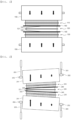
- FIG. 1 is a view showing a bi-cell lamination process using a conventional lamination apparatus.
- an electrode assembly is a bi-cell configured such that a first electrode 110, a separator 140, a second electrode 120, a separator 140, and a third electrode 130 are sequentially stacked.
- the thicknesses of electrode mixture layers 122 applied to opposite surfaces of an electrode current collector 121 of the second electrode 120 are not uniform.
- the left-side thickness of each of the electrode mixture layers is small, and the right-side thickness of each of the electrode mixture layers is large.
- a pair of pressing rolls 150 is disposed above the first electrode 110 and under the third electrode 130 to press the electrode assembly. At this time, the pressing rolls 150 apply uniform pressure to the entireties of the surfaces of the first electrode 110 and the third electrode 130 that abut the pressing rolls. As a result, it is difficult for the left sides of the electrode mixture layers 122 of the second electrode to be brought into tight contact with the left side of the first electrode 110 and the left side of the third electrode 130.
- bi-cells must be disposed on a long sheet type separation film one by one, and an electrode separated from one bi-cell may be disposed together with another bi-cell.
- Such a problem may occur due to poor adhesion between the first electrode and the second electrode and between the third electrode and the second electrode when the thickness of the second electrode disposed at the middle, among the electrodes constituting the bi-cell, is non-uniform.
- KR 10 2020 0066901 A discloses an electrode assembly manufacturing apparatus comprising a thickness measurement unit measuring a thickness of one or more from an electrode and a separation film; and a lamination unit pressing the electrode and the separation film, which are laminated while passing through the thickness measurement unit, while passing the electrode and the separation film between a pair of vertically arranged pressing roll units to bond the electrode and the separation film.
- JP 2014-191880 A discloses a manufacturing method including a rolling step of forming an electrode composition layer on a base substrate of which the coefficient of friction with powder is settled within a predetermined range, by compression-molding the powder on the base material while using a rolling device capable of making a rotation speed of one pressing roll between a pair of pressing rolls of which the rotation axes are parallel and which are disposed substantially horizontally, different from a rotation speed of the other pressing roll; a measuring step of measuring a unit weight of the powder with respect to the base material in the rolling step; and a change step of changing a speed ratio of the rotation speed of the one pressing roll with respect to the rotation speed of the other pressing roll on the basis of a result of the measurement in the measuring step.
- US 9,246,186 B2 discloses a fabricating method of a unit structure for accomplishing an electrode assembly formed by a stacking method, and an electrochemical cell including the same are disclosed.
- the fabricating method of the electrode assembly is characterized with fabricating the unit structure by conducting a first process of laminating and forming a bicell having a first electrode/separator/second electrode/separator/first electrode structure, and conducting a second process of laminating first separator/second electrode/second separator one by one on one of the first electrode among two of the first electrodes.
- KR 10-2028611 B1 discloses lamination apparatus comprising an inlet through which an electrode assembly of a web structure is introduced; a first heating unit which heats the electrode assembly; a discharge unit which discharges the thermally bonded electrode assembly; a pressing unit which has a press roll; and a second heating unit which secondarily heats and rolling-presses the primarily heated electrode assembly.
- the present invention has been made in view of the above problems, and it is an object of the present invention to provide a lamination apparatus including a pressing roll configured such that pressing force thereof is adjustable in order to prevent decrease in force of adhesion between electrodes due to deviation in thickness between electrode mixture layers constituting a bi-cell and an electrode assembly manufactured using the same.
- a lamination apparatus to accomplish the above object, which is a lamination apparatus for manufacture of an electrode assembly, includes a pressing roll configured to press electrodes constituting the electrode assembly, a rotary shaft configured to rotate the pressing roll, a pressing cylinder configured to adjust a pressing force applied to the pressing roll, and a thickness measurement sensor configured to measure the thickness of an electrode mixture layer, wherein the pressing cylinder comprises a first pressing cylinder and a second pressing cylinder coupled to opposite ends of the rotary shaft, respectively; and the lamination apparatus is configured such that a pressing force applied by the first pressing cylinder and a pressing force applied by the second pressing cylinder are different from each other.
- the thickness measurement sensor may include a first thickness measurement sensor and a second thickness measurement sensor disposed at opposite ends of the electrode, respectively.
- the lamination apparatus may further include a controller configured to control the pressing force applied by the pressing cylinder when a difference occurs between the thickness of the electrode measured by the first thickness measurement sensor and the thickness of the electrode measured by the second thickness measurement sensor.
- the pressing roll may be configured to more strongly press the electrode at the position at which the thickness of the electrode is smaller when a difference occurs between the thickness of the electrode measured by the first thickness measurement sensor and the thickness of the electrode measured by the second thickness measurement sensor.
- the electrode assembly may be a bi-cell having a structure in which a first electrode, a separator, a second electrode, a separator, and a third electrode are stacked.
- the lamination apparatus may further include a first electrode supply unit, a second electrode supply unit, and a third electrode supply unit, wherein the thickness measurement sensor may measure the thickness of a second electrode supplied from the second electrode supply unit.
- each of the electrodes may be a double-sided electrode having electrode mixtures coated on opposite surfaces of an electrode current collector, and the lamination apparatus may be disposed at each of an upper surface and a lower surface of the electrode.
- the thickness measurement sensor may include a radiation portion configured to radiate a beta ray transmitted through the electrode and a receiving portion configured to sense the beta ray radiated by the radiation portion, and the radiation portion may be configured to be disposed at any one of the upper surface and the lower surface of the electrode while the receiving portion may be disposed at the other.
- pressing forces applied to a first end and a second end of an upper pressing roll configured to be disposed at the upper surface of the electrode may be configured to be set independent of pressing forces applied to a first end and a second end of a lower pressing roll configured to be disposed at the lower surface of the electrode.
- the pressing roll may be configured to be capable of being heated.
- the electrode assembly may be a bi-cell having a structure in which a first electrode, a separator, a second electrode, a separator, and a third electrode are sequentially stacked, and the first electrode and the second electrode may be coupled to each other, and the second electrode and the third electrode may be coupled to each other, throughout outer peripheries thereof.
- the present invention may provide various combinations of the above solving means.
- an electrode mixture layer of a second electrode of the bi-cell which is located at a middle thereof, using a thickness measurement sensor, whereby it is possible to form an adhesive surface throughout an interface between a first electrode and a separator and an interface between the separator and the second electrode.
- the pressing roll is configured such that the temperature of the pressing roll can be increased, whereby it is possible to further increase the force of adhesion between the electrodes.
- bi-cells may be disposed on a separation sheet one by one when a stacked and folded type electrode assembly is manufactured, whereby it is possible to reduce incorrect bi-cell placement, and therefore it is possible to secure productivity of the electrode assembly.
- FIG. 2 is a front view showing the state in which a bi-cell is laminated using a lamination apparatus according to the present invention.
- pressing rolls 251 are disposed above and under an electrode assembly.
- the electrode assembly is a bi-cell configured such that a first electrode 210, a separator 240, a second electrode 220, a separator 240, and a third electrode 230 are sequentially stacked.
- the first electrode 210 and the third electrode 230 are electrodes having the same polarity
- the second electrode 220 is an electrode having a polarity different from the polarity of the first electrode 210 and the third electrode 230.
- Each of the first electrode 210, the second electrode 220, and the third electrode 230 is a double-sided electrode having electrode mixture layers applied to opposite surfaces of an electrode current collector.
- each of the electrode mixture layers 222 applied to the upper surface and the lower surface of the electrode current collector 221 of the second electrode 220 is not uniform.
- the left-side thickness of each of the electrode mixture layers is relatively small, and the right-side thickness of each of the electrode mixture layers is relatively large.
- a first pressing cylinder 253 and a second pressing cylinder 263 configured to be independently controlled are coupled to opposite ends of each of the rotary shafts 252, which are configured to rotate the pressing rolls 251.
- pressing force applied by the first pressing cylinder 253 and pressing force applied by the second pressing cylinder 263 are different from each other.
- the first pressing cylinder 253 is located so as to be adjacent to the part at which the thickness of each of the electrode mixture layers is relatively small
- the second pressing cylinder 263 is located so as to be adjacent to the part at which the thickness of each of the electrode mixture layers is relatively large.
- the first electrode 210 and the third electrode 230 may be deeply pressed in a direction toward the second electrode 220. Consequently, it is possible to completely adhere the electrodes to each other at the left part, at which the thickness of each of the electrode mixture layers 222 is relatively small as well as the right part, at which the thickness of each of the electrode mixture layers 222 is relatively large.
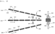
- FIG. 3 is a side view showing the state in which a bi-cell is laminated using a lamination apparatus according to an embodiment
- FIG. 4 is a perspective view showing the state in which a controller is added to the lamination apparatus of FIG. 3 .
- the lamination apparatus which is configured to manufacture a bi-cell, includes a pressing roll 351 configured to press electrodes constituting an electrode assembly, a rotary shaft 352 configured to rotate the pressing roll 351, a first pressing cylinder 353 and a second pressing cylinder 363 configured to adjust pressing force applied to the pressing roll 351, and a first thickness measurement sensor 381 and a second thickness measurement sensor 382 configured to measure the thickness of one of the electrodes.
- the lamination apparatus includes a first electrode supply unit configured to supply a first electrode 310, a second electrode supply unit configured to supply a second electrode 320, and a third electrode supply unit configured to supply a third electrode 330, and the thickness measurement sensors measure the thickness of the second electrode 320 supplied from the second electrode supply unit.
- the electrode assembly is a bi-cell configured such that the first electrode 310, a separator 340, the second electrode 320, a separator 340, and the third electrode 330 are sequentially stacked.
- the first electrode 310 is configured such that electrode mixture layers 312 are formed on opposite surfaces of an electrode current collector 311
- the second electrode 320 is configured such that electrode mixture layers 322 are formed on opposite surfaces of an electrode current collector 321
- the third electrode 330 is configured such that electrode mixture layers 332 are formed on opposite surfaces of an electrode current collector 331.
- the first electrode 310 and the third electrode 330 are electrodes having the same polarity
- the second electrode 320 is an electrode having a polarity different from the polarity of the first electrode 310 and the third electrode 330. That is, when the first electrode and the third electrode are positive electrodes, the second electrode is a negative electrode. When the first electrode and the third electrode are negative electrodes, the second electrode is a positive electrode.
- the separator 340 is attached to an outer surface of the electrode mixture layer 312 of the first electrode 310 that faces the second electrode 320, and the first electrode 310 and the separator 340 are cut into a unit electrode by a cutter 390 in a step before lamination.
- the separator 340 is attached to an outer surface of the electrode mixture layer 332 of the third electrode 330 that faces the second electrode 320, and the third electrode 330 and the separator 340 are cut into a unit electrode by a cutter 390 in the step before lamination.
- No separator 340 is attached to an outer surface of the electrode mixture layer 322 of the second electrode 320, and the second electrode 320 is cut into a unit electrode by a cutter 390 in the step before lamination.
- the pressing cylinders include a first pressing cylinder 353 and a second pressing cylinder 363 coupled to opposite ends of the rotary shaft 352, respectively, and the pressing cylinders may be individually controlled such that pressing forces applied to the pressing roll are different from each other.
- the thickness of the electrode mixture layer 322 of the second electrode 320 may not be uniform.
- the first thickness measurement sensor 381 and the second thickness measurement sensor 382, which are configured to measure the thickness of the electrode mixture layer, are disposed at opposite ends of the second electrode 320, respectively.
- the first thickness measurement sensor 381 and the second thickness measurement sensor 382 are disposed respectively at opposite ends of the second electrode in a y-axis direction, which is perpendicular to a movement direction x of the electrode.
- the size of a gap between the first electrode and the second electrode and the size of a gap between the third electrode and the second electrode may be recognized when thickness deviation of the second electrode is recognized. Consequently, it is important to check thickness deviation of the second electrode.
- Each of the first thickness measurement sensor 381 and the second thickness measurement sensor 382 may be constituted by a pair of an upper sensor located above the second electrode and a lower sensor located under the second electrode. A beta ray emitted from the lower sensor is transmitted through the second electrode and reaches the upper sensor. When the loading amount of the electrode mixture layer of the second electrode is larger, the residual amount of the beta ray that reaches the upper sensor is smaller. Consequently, it is possible to measure the thickness of the electrode mixture layer of the second electrode by the principle by which the loading amount of the electrode mixture layer is calculated based on the residual amount of the beta ray measured by the upper sensor.
- the lamination apparatus may include a controller 370 configured to control pressing forces of the first pressing cylinder 353 and the second pressing cylinder 363 based on the thicknesses of the electrode mixture layer measured by the first thickness measurement sensor 381 and the second thickness measurement sensor 382. Consequently, it is possible to calculate values measured through the first thickness measurement sensor and the second thickness measurement sensor in real time, whereby it is possible to adjust the pressing forces of the pressing cylinders without intervention of a worker.
- the first thickness measurement sensor 381 and the second thickness measurement sensor 382 may be disposed above an electrode that enters the cutter 390, as shown in FIG. 3 , or may be disposed between the cutter 390, which cuts an electrode sheet into a unit electrode, and the pressing roll, as shown in FIG. 4 .
- the first thickness measurement sensor 381 and the second thickness measurement sensor 382 may be disposed at an upper surface and a lower surface of the second electrode 320. Consequently, it is possible to measure the thicknesses of opposite ends of the electrode mixture layer 322 applied to the upper surface of the second electrode 320 in the y-axis direction and to measure the thicknesses of opposite ends of the electrode mixture layer 322 applied to the lower surface of the second electrode 320 in the y-axis direction.
- the pressing forces of the first pressing cylinder 353 and the second pressing cylinder 363 of the lamination apparatus disposed at the upper surface of the second electrode 320 may be controlled independent of the pressing forces of the first pressing cylinder 353 and the second pressing cylinder 363 of the lamination apparatus disposed at the lower surface of the second electrode 320.
- pressing forces applied to a first end and a second end of the upper pressing roll disposed at the upper surface of the second electrode 320 may be set independent of pressing forces applied to a first end and a second end of the lower pressing roll disposed at the lower surface of the second electrode 320.
- the first electrode 310, the second electrode 320, and the third electrode 330 are stacked between the pressing rolls 351 in the state in which separators (not shown) are interposed between the respective electrodes.
- the thickness of the electrode adjacent to the first pressing cylinder 353 is relatively small, whereby the pressing force of the first pressing cylinder 353 is greater than the pressing force of the second pressing cylinder 363. Consequently, the first pressing cylinder 353 and the second pressing cylinder 363 press the pressing rolls 351 so as to come into tight contact with the outermost electrodes of the bi-cell, and the pressing roll 351 adjacent to the rotary shaft 352 connected to the first pressing cylinder 353 is strongly pressed while being moved so as to come into tighter contact with the bi-cell in a direction parallel to a z-axis.
- the pressing rolls 351 may be configured to be capable of being heated, and therefore the pressing rolls may press the bi-cell in a heated state. Consequently, it is possible to further increase the force of adhesion between the electrodes.
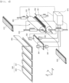
- FIG. 5 is a side view showing the state in which a bi-cell is laminated using a lamination apparatus according to another embodiment
- FIG. 6 is a perspective view showing the state in which a controller is added to the lamination apparatus of FIG. 5 .
- a construction including a first electrode 310, a second electrode 320, a third electrode 330, and a separator 340, which constitute a bi-cell, a pressing roll 351, a rotary shaft 352, a first pressing cylinder 353, and a second pressing cylinder 363 is identical to the construction shown in FIGS. 3 and 4 , and therefore, a description given with reference to FIGS. 3 and 4 is equally applied thereto.
- Thickness measurement sensors shown in FIGS. 5 and 6 may include a first thickness measurement sensor 383 and a second thickness measurement sensor 384 disposed respectively at opposite ends of the second electrode 320 parallel in the y-axis direction, whereby it is possible to measure the thicknesses of an electrode mixture layer 322 at positions corresponding to the opposite ends of the second electrode.
- the first thickness measurement sensor 383 and the second thickness measurement sensor 384 include radiation portions 383a and 384a configured to radiate a beta ray capable of being transmitted through the second electrode 320 and receiving portions 383b and 384b configured to sense the beta ray radiated by the radiation portions 383a and 384a, respectively.
- the radiation portions 383a and 384a are disposed at an upper surface of the second electrode 320, and the receiving portions 383b and 384b are disposed at a lower surface of the second electrode.
- the radiation portions and the receiving portions may be disposed at positions opposite the positions shown in the figures.
- the thickness of the second electrode When the thickness of the second electrode is larger, the residual amount of the beta ray that reaches the receiving portions is smaller. Consequently, it is possible to measure the total thickness of the electrode mixture layers applied to the upper surface and the lower surface of the second electrode 320 using the first thickness measurement sensor 383 and the second thickness measurement sensor 384.
- laser sensors may be disposed above and under the second electrode, and reflection time of a radiated laser may be measured, whereby the thickness of the second electrode may be measured.
- the bi-cell configured such that the first electrode, the separator, the second electrode, the separator, and the third electrode are sequentially stacked is manufactured using the lamination apparatus according to the present invention, as described above, adhesion may be achieved between the first electrode and the second electrode and between the second electrode and the third electrode throughout the outer surfaces thereof.
- a bi-cell was manufactured in order to check influence of pressing force applied when the bi-cell was laminated on the force of adhesion between electrodes and separators.
- FIG. 7 is a vertical sectional view and a plan view of a bi-cell manufactured according to Experimental Example.
- the bi-cell is configured such that a first electrode 310, an upper separator 441, a second electrode 320, a lower separator 442, and a third electrode 330 are sequentially stacked, wherein the first electrode 310 and the third electrode 330 are positive electrodes, and the second electrode 320 is a negative electrode.
- the bi-cell was divided into three regions in plan view.
- the bi-cell was divided into a tab portion Tab, which was a part adjacent to electrode tabs, a lower portion Bottom, which was opposite the tab portion, and a middle portion M, which was located between the tab portion and the lower portion.
- the forces of adhesion between (A) the second electrode 320 and the upper separator 441, (B) the second electrode 320 and the lower separator 442, (C) the first electrode 310 and the upper separator 441, and (D) the third electrode 330 and the lower separator 442 were measured.
- the second electrode 320 was fixed to a horizontal plate, the first electrode 310 and the upper separator 441 were fixed to a grip type jig, and the first electrode and the upper separator were pulled vertically so as to be peeled off from the second electrode, whereby the adhesive force was measured.
- the second electrode 320 was fixed to the horizontal plate, the third electrode 330 and the lower separator 442 were fixed to the grip type jig, and the third electrode and the lower separator were pulled vertically so as to be peeled off from the second electrode, whereby the adhesive force was measured.
- the first electrode 310 was fixed to the horizontal plate, the upper separator 441 was fixed to the grip type jig, and the first electrode was pulled vertically so as to be peeled off from the upper separator, whereby the adhesive force was measured.
- the third electrode 330 was fixed to the horizontal plate, the lower separator 442 was fixed to the grip type jig, and the third electrode was pulled vertically so as to be peeled off from the lower separator, whereby the adhesive force was measured.
- a universal testing machine (UTM) manufactured by Amtek was used as an adhesive force measurement device.
- the adhesive force measured when the pressing force is high is higher than the adhesive force measured when the pressing force is low.
Landscapes
- Chemical & Material Sciences (AREA)
- Chemical Kinetics & Catalysis (AREA)
- Electrochemistry (AREA)
- General Chemical & Material Sciences (AREA)
- Engineering & Computer Science (AREA)
- Manufacturing & Machinery (AREA)
- Battery Electrode And Active Subsutance (AREA)
- Secondary Cells (AREA)
Claims (10)
- Laminierungsvorrichtung zur Herstellung einer Elektrodenanordnung, wobei die Laminierungsvorrichtung umfasst:eine Presswalze, die konfiguriert ist, um Elektroden zu pressen, die die Elektrodenanordnung bilden;eine Drehwelle, die konfiguriert ist, um die Presswalze zu drehen;einen Presszylinder, der konfiguriert ist, um eine Presskraft einzustellen, die auf die Presswalze ausgeübt wird; undeinen Dickenmesssensor, der konfiguriert ist, um eine Dicke einer Elektrodenmischungsschicht zu messen;wobei der Presszylinder einen ersten Presszylinder und einen zweiten Presszylinder umfasst, die jeweils mit gegenüberliegenden Enden der Drehwelle gekoppelt sind; unddie Laminierungsvorrichtung derart konfiguriert ist, dass eine Presskraft, die durch den ersten Presszylinder ausgeübt wird, und eine Presskraft, die durch den zweiten Presszylinder ausgeübt wird, voneinander verschieden sind.
- Laminierungsvorrichtung nach Anspruch 1, wobei der Dickenmesssensor einen ersten Dickenmesssensor und einen zweiten Dickenmesssensor umfasst, die jeweils an gegenüberliegenden Enden der Elektrode angeordnet sind.
- Laminierungsvorrichtung nach Anspruch 2, ferner umfassend eine Steuerung, die konfiguriert ist, um die Presskraft zu steuern, die durch den Presszylinder ausgeübt wird, wenn eine Differenz zwischen der Dicke der Elektrode, die durch den ersten Dickenmesssensor gemessen wird, und der Dicke der Elektrode, die durch den zweiten Dickenmesssensor gemessen wird, auftritt.
- Laminierungsvorrichtung nach Anspruch 2, wobei die Presswalze konfiguriert ist, um die Elektrode an einer Position, an der die Dicke der Elektrode kleiner ist, stärker zu pressen, wenn eine Differenz zwischen der Dicke der Elektrode, die durch den ersten Dickenmesssensor gemessen wird, und der Dicke der Elektrode, die durch den zweiten Dickenmesssensor gemessen wird, auftritt.
- Laminierungsvorrichtung nach Anspruch 1, wobei die Elektrodenanordnung eine Zweizelle mit einer Struktur ist, in der eine erste Elektrode, ein Separator, eine zweite Elektrode, ein Separator und eine dritte Elektrode gestapelt sind.
- Laminierungsvorrichtung nach Anspruch 1, ferner umfassend:eine erste Elektrodenversorgungseinheit;eine zweite Elektrodenversorgungseinheit; undeine dritte Elektrodenversorgungseinheit,wobei der Dickenmesssensor eine Dicke einer zweiten Elektrode misst, die von der zweiten Elektrodenversorgungseinheit versorgt wird.
- Laminierungsvorrichtung nach Anspruch 1, wobeijede der Elektroden eine doppelseitige Elektrode ist, die Elektrodenmischungen aufweist, die auf gegenüberliegenden Oberflächen eines Elektrodenstromabnehmers beschichtet sind, unddie Laminierungsvorrichtung an jeder von einer oberen Oberfläche und einer unteren Oberfläche der Elektrode angeordnet ist.
- Laminierungsvorrichtung nach Anspruch 7, wobei der Dickenmesssensor umfasst:einen Strahlungsabschnitt, der konfiguriert ist, um einen Betastrahl zu strahlen, der durch die Elektrode übertragen wird; undeinen Empfangsabschnitt, der konfiguriert ist, um den Betastrahl zu erfassen, der von dem Strahlungsabschnitt abgestrahlt wird, undder Strahlungsabschnitt konfiguriert ist, um an einer von der oberen Oberfläche und der unteren Oberfläche der Elektrode angeordnet zu sein, während der Empfangsabschnitt an der anderen angeordnet ist.
- Laminierungsvorrichtung nach Anspruch 7, wobei Presskräfte, die auf ein erstes Ende und ein zweites Ende einer oberen Presswalze ausgeübt werden, die konfiguriert ist, um an der oberen Oberfläche der Elektrode angeordnet zu sein, konfiguriert sind, um unabhängig von Presskräften eingestellt zu werden, die auf ein erstes Ende und ein zweites Ende einer unteren Presswalze ausgeübt werden, die konfiguriert ist, um an der unteren Oberfläche der Elektrode angeordnet zu sein.
- Laminierungsvorrichtung nach Anspruch 1, wobei die Presswalze konfiguriert ist, um in der Lage zu sein, erwärmt zu werden.
Applications Claiming Priority (2)
| Application Number | Priority Date | Filing Date | Title |
|---|---|---|---|
| KR1020210016895A KR102885404B1 (ko) | 2021-02-05 | 2021-02-05 | 가압력 조절이 가능한 라미네이션 롤을 포함하는 라미네이션 장치 및 이를 이용하여 제조된 전극조립체 |
| PCT/KR2022/001614 WO2022169237A1 (ko) | 2021-02-05 | 2022-01-28 | 가압력 조절이 가능한 가압롤을 포함하는 라미네이션 장치 및 이를 이용하여 제조된 전극조립체 |
Publications (3)
| Publication Number | Publication Date |
|---|---|
| EP4131534A1 EP4131534A1 (de) | 2023-02-08 |
| EP4131534A4 EP4131534A4 (de) | 2024-09-11 |
| EP4131534B1 true EP4131534B1 (de) | 2025-06-18 |
Family
ID=82742307
Family Applications (1)
| Application Number | Title | Priority Date | Filing Date |
|---|---|---|---|
| EP22749986.0A Active EP4131534B1 (de) | 2021-02-05 | 2022-01-28 | Laminiervorrichtung mit einer presswalze zur einstellung der druckkraft und damit hergestellte elektrodenanordnung |
Country Status (7)
| Country | Link |
|---|---|
| US (1) | US20230187679A1 (de) |
| EP (1) | EP4131534B1 (de) |
| KR (1) | KR102885404B1 (de) |
| CN (1) | CN115428211A (de) |
| ES (1) | ES3041683T3 (de) |
| HU (1) | HUE072310T2 (de) |
| WO (1) | WO2022169237A1 (de) |
Families Citing this family (7)
| Publication number | Priority date | Publication date | Assignee | Title |
|---|---|---|---|---|
| KR102889127B1 (ko) | 2022-09-06 | 2025-11-19 | 주식회사 엘지에너지솔루션 | 배터리의 이상을 감지하는 전자 장치 및 이의 동작 방법 |
| KR102617497B1 (ko) * | 2022-09-15 | 2023-12-27 | 주식회사 엘지에너지솔루션 | 음극용 자성 정렬 장치 및 이를 이용한 음극의 제조방법 |
| DE102022128222A1 (de) * | 2022-10-25 | 2024-04-25 | Körber Technologies Gmbh | Laminiervorrichtung zum Laminieren von mehrlagigen Endlosbahnen zur Herstellung von Energiezellen |
| JP2025536239A (ja) * | 2023-01-13 | 2025-11-05 | ケーニッヒ ウント バウアー アー・ゲー | キャリヤ基材を粉末状の材料でコーティングするための装置 |
| US20260008262A1 (en) * | 2023-01-13 | 2026-01-08 | Koenig & Bauer Ag | Device for coating a carrier substrate with a powdered material |
| WO2024165535A1 (de) * | 2023-02-08 | 2024-08-15 | Koenig & Bauer Ag | Vorrichtung, maschine und verfahren zum beschichten eines bahnförmigen trägersubstrates mit einem trockenfilm |
| WO2024183996A1 (de) * | 2023-03-07 | 2024-09-12 | Koenig & Bauer Ag | Vorrichtung, maschine und verfahren zum beschichten eines bahnförmigen trägersubstrates mit einem trockenfilm |
Family Cites Families (15)
| Publication number | Priority date | Publication date | Assignee | Title |
|---|---|---|---|---|
| JP2574699B2 (ja) * | 1989-04-21 | 1997-01-22 | ダイソー 株式会社 | 酸素発生陽極及びその製法 |
| KR101419362B1 (ko) * | 2012-06-18 | 2014-07-15 | 주식회사 씨엘디 | 라미네이팅 장치 |
| KR101528027B1 (ko) * | 2012-06-28 | 2015-06-12 | 주식회사 엘지화학 | 전극조립체의 제조공정 |
| US9647255B2 (en) * | 2012-12-21 | 2017-05-09 | Amogreentech Co., Ltd. | Porous separation membrane, secondary battery using same, and method for manufacturing said secondary battery |
| JP6086384B2 (ja) * | 2013-03-26 | 2017-03-01 | 日本ゼオン株式会社 | リチウムイオン二次電池電極用シートの製造方法 |
| ITMO20130311A1 (it) * | 2013-11-11 | 2015-05-12 | Kemet Electronics Italia S R L | Metodo di laminazione |
| WO2015141631A1 (ja) * | 2014-03-17 | 2015-09-24 | 日産自動車株式会社 | バッテリセルの加圧装置 |
| KR101816765B1 (ko) * | 2015-06-04 | 2018-01-10 | 주식회사 엘지화학 | 전극 조립체의 라미네이션용 보호 부재 및 이를 이용한 이차 전지의 제조 방법 |
| KR20180044769A (ko) * | 2016-10-24 | 2018-05-03 | 주식회사 엘지화학 | 스택-폴딩 셀의 제조방법 |
| IT201600119013A1 (it) * | 2016-11-24 | 2018-05-24 | Manz Italy Srl | Produzione di Dispositivi di Accumulo di Energia Elettrica |
| KR102225091B1 (ko) * | 2017-01-18 | 2021-03-09 | 주식회사 엘지화학 | 고용량화를 위한 분리막 구조를 가진 전극조립체 및 이를 포함하는 전지셀 |
| KR102028611B1 (ko) | 2018-07-27 | 2019-10-04 | 장명희 | 이차전지 제조용 라미네이션 장치 |
| KR102143643B1 (ko) * | 2018-08-24 | 2020-08-11 | 주식회사 엘지화학 | 전고체 전지용 전극 또는 고체 전해질의 제조 장치 |
| KR102759173B1 (ko) * | 2018-12-03 | 2025-01-24 | 주식회사 엘지에너지솔루션 | 전극 조립체 제조장치 및 전극 조립체 제조방법 |
| KR102372310B1 (ko) | 2019-08-06 | 2022-03-10 | 한국전력공사 | 간접활선용 완철을 이용한 간접활선 작업방법 |
-
2021
- 2021-02-05 KR KR1020210016895A patent/KR102885404B1/ko active Active
-
2022
- 2022-01-28 ES ES22749986T patent/ES3041683T3/es active Active
- 2022-01-28 EP EP22749986.0A patent/EP4131534B1/de active Active
- 2022-01-28 HU HUE22749986A patent/HUE072310T2/hu unknown
- 2022-01-28 WO PCT/KR2022/001614 patent/WO2022169237A1/ko not_active Ceased
- 2022-01-28 CN CN202280003448.1A patent/CN115428211A/zh active Pending
- 2022-01-28 US US17/920,247 patent/US20230187679A1/en active Pending
Also Published As
| Publication number | Publication date |
|---|---|
| WO2022169237A1 (ko) | 2022-08-11 |
| ES3041683T3 (en) | 2025-11-13 |
| EP4131534A4 (de) | 2024-09-11 |
| CN115428211A (zh) | 2022-12-02 |
| EP4131534A1 (de) | 2023-02-08 |
| HUE072310T2 (hu) | 2025-11-28 |
| KR20220113110A (ko) | 2022-08-12 |
| US20230187679A1 (en) | 2023-06-15 |
| KR102885404B1 (ko) | 2025-11-13 |
Similar Documents
| Publication | Publication Date | Title |
|---|---|---|
| EP4131534B1 (de) | Laminiervorrichtung mit einer presswalze zur einstellung der druckkraft und damit hergestellte elektrodenanordnung | |
| KR101609424B1 (ko) | 전극조립체의 제조방법 | |
| TWI501443B (zh) | 製造電極組件的方法 | |
| KR102759173B1 (ko) | 전극 조립체 제조장치 및 전극 조립체 제조방법 | |
| KR20210058170A (ko) | 전극 조립체 제조방법과 전극 조립체 제조장치 | |
| KR101586881B1 (ko) | 폴리머 2차전지 셀용 전극조립체 | |
| EP4109613B1 (de) | Elektrodenherstellungsvorrichtung mit elektrodenausrichtungseinheit und elektrodenbauanlage, die diese enthält | |
| JP2007506224A (ja) | 高分子バッテリーの組合せ体の積み重ね装置および方法 | |
| US20230126211A1 (en) | Separator Sheet Adhesion Apparatus | |
| KR102608541B1 (ko) | 전극 조립체 | |
| EP4286830B1 (de) | Verfahren zur bewertung der adhäsion eines separators | |
| KR20220025500A (ko) | 이차전지 제조 장치 | |
| EP4216359A1 (de) | Separator mit konkav-konvexem teil, elektrodenanordnung damit und verfahren zur herstellung der elektrodenanordnung | |
| US20230343982A1 (en) | Mono-Cell Manufacturing Apparatus with Gloss Meter and Manufacturing Method Using the Same | |
| US20230134414A1 (en) | Laminator for Manufacture of Unit Structural Bodies with Increased Force of Adhesion | |
| EP4597722A2 (de) | Separator und elektrodenanordnung | |
| CN117296176A (zh) | 电极组件、制造该电极组件的设备和制造该电极组件的方法 | |
| KR102540600B1 (ko) | 전극 조립체 | |
| US12552062B2 (en) | Electrode manufacturing apparatus including electrode alignment unit and electrode assembly manufacturing apparatus | |
| KR20250141930A (ko) | 폴딩 분리막, 이를 포함하는 전극조립체, 및 상기 전극조립체의 제조방법 | |
| CN118160121A (zh) | 等离子体处理装置及包括该等离子体处理装置的二次电池用层压系统 | |
| CN117337501A (zh) | 电极组件、其制造设备及其制造方法 | |
| KR20240036928A (ko) | 이차전지 제조장치 및 이를 이용한 이차전지 제조 방법 | |
| CN117355969A (zh) | 电极组件、其制造设备及其制造方法 | |
| KR20230036478A (ko) | 라미네이션 장치 및 방법, 그리고 그에 의해 제조되는 이차 전지 셀 |
Legal Events
| Date | Code | Title | Description |
|---|---|---|---|
| STAA | Information on the status of an ep patent application or granted ep patent |
Free format text: STATUS: THE INTERNATIONAL PUBLICATION HAS BEEN MADE |
|
| PUAI | Public reference made under article 153(3) epc to a published international application that has entered the european phase |
Free format text: ORIGINAL CODE: 0009012 |
|
| STAA | Information on the status of an ep patent application or granted ep patent |
Free format text: STATUS: REQUEST FOR EXAMINATION WAS MADE |
|
| 17P | Request for examination filed |
Effective date: 20221101 |
|
| AK | Designated contracting states |
Kind code of ref document: A1 Designated state(s): AL AT BE BG CH CY CZ DE DK EE ES FI FR GB GR HR HU IE IS IT LI LT LU LV MC MK MT NL NO PL PT RO RS SE SI SK SM TR |
|
| DAV | Request for validation of the european patent (deleted) | ||
| DAX | Request for extension of the european patent (deleted) | ||
| A4 | Supplementary search report drawn up and despatched |
Effective date: 20240808 |
|
| RIC1 | Information provided on ipc code assigned before grant |
Ipc: H01M 10/04 20060101AFI20240802BHEP |
|
| REG | Reference to a national code |
Ref country code: DE Ref legal event code: R079 Free format text: PREVIOUS MAIN CLASS: H01M0010040000 Ipc: H01M0004040000 Ref country code: DE Ref legal event code: R079 Ref document number: 602022016149 Country of ref document: DE Free format text: PREVIOUS MAIN CLASS: H01M0010040000 Ipc: H01M0004040000 |
|
| GRAP | Despatch of communication of intention to grant a patent |
Free format text: ORIGINAL CODE: EPIDOSNIGR1 |
|
| STAA | Information on the status of an ep patent application or granted ep patent |
Free format text: STATUS: GRANT OF PATENT IS INTENDED |
|
| RIC1 | Information provided on ipc code assigned before grant |
Ipc: H01M 50/46 20210101ALI20250320BHEP Ipc: H01M 10/04 20060101ALI20250320BHEP Ipc: H01M 4/04 20060101AFI20250320BHEP |
|
| INTG | Intention to grant announced |
Effective date: 20250402 |
|
| GRAS | Grant fee paid |
Free format text: ORIGINAL CODE: EPIDOSNIGR3 |
|
| GRAA | (expected) grant |
Free format text: ORIGINAL CODE: 0009210 |
|
| STAA | Information on the status of an ep patent application or granted ep patent |
Free format text: STATUS: THE PATENT HAS BEEN GRANTED |
|
| P01 | Opt-out of the competence of the unified patent court (upc) registered |
Free format text: CASE NUMBER: APP_20639/2025 Effective date: 20250430 |
|
| AK | Designated contracting states |
Kind code of ref document: B1 Designated state(s): AL AT BE BG CH CY CZ DE DK EE ES FI FR GB GR HR HU IE IS IT LI LT LU LV MC MK MT NL NO PL PT RO RS SE SI SK SM TR |
|
| REG | Reference to a national code |
Ref country code: GB Ref legal event code: FG4D |
|
| REG | Reference to a national code |
Ref country code: CH Ref legal event code: EP |
|
| REG | Reference to a national code |
Ref country code: DE Ref legal event code: R096 Ref document number: 602022016149 Country of ref document: DE |
|
| REG | Reference to a national code |
Ref country code: CH Ref legal event code: EP |
|
| REG | Reference to a national code |
Ref country code: IE Ref legal event code: FG4D |
|
| PG25 | Lapsed in a contracting state [announced via postgrant information from national office to epo] |
Ref country code: FI Free format text: LAPSE BECAUSE OF FAILURE TO SUBMIT A TRANSLATION OF THE DESCRIPTION OR TO PAY THE FEE WITHIN THE PRESCRIBED TIME-LIMIT Effective date: 20250618 |
|
| REG | Reference to a national code |
Ref country code: LT Ref legal event code: MG9D |
|
| PG25 | Lapsed in a contracting state [announced via postgrant information from national office to epo] |
Ref country code: NO Free format text: LAPSE BECAUSE OF FAILURE TO SUBMIT A TRANSLATION OF THE DESCRIPTION OR TO PAY THE FEE WITHIN THE PRESCRIBED TIME-LIMIT Effective date: 20250918 Ref country code: GR Free format text: LAPSE BECAUSE OF FAILURE TO SUBMIT A TRANSLATION OF THE DESCRIPTION OR TO PAY THE FEE WITHIN THE PRESCRIBED TIME-LIMIT Effective date: 20250919 |
|
| PG25 | Lapsed in a contracting state [announced via postgrant information from national office to epo] |
Ref country code: BG Free format text: LAPSE BECAUSE OF FAILURE TO SUBMIT A TRANSLATION OF THE DESCRIPTION OR TO PAY THE FEE WITHIN THE PRESCRIBED TIME-LIMIT Effective date: 20250618 |
|
| PG25 | Lapsed in a contracting state [announced via postgrant information from national office to epo] |
Ref country code: HR Free format text: LAPSE BECAUSE OF FAILURE TO SUBMIT A TRANSLATION OF THE DESCRIPTION OR TO PAY THE FEE WITHIN THE PRESCRIBED TIME-LIMIT Effective date: 20250618 |
|
| PG25 | Lapsed in a contracting state [announced via postgrant information from national office to epo] |
Ref country code: RS Free format text: LAPSE BECAUSE OF FAILURE TO SUBMIT A TRANSLATION OF THE DESCRIPTION OR TO PAY THE FEE WITHIN THE PRESCRIBED TIME-LIMIT Effective date: 20250918 |
|
| REG | Reference to a national code |
Ref country code: NL Ref legal event code: MP Effective date: 20250618 |
|
| PG25 | Lapsed in a contracting state [announced via postgrant information from national office to epo] |
Ref country code: LV Free format text: LAPSE BECAUSE OF FAILURE TO SUBMIT A TRANSLATION OF THE DESCRIPTION OR TO PAY THE FEE WITHIN THE PRESCRIBED TIME-LIMIT Effective date: 20250618 |
|
| REG | Reference to a national code |
Ref country code: ES Ref legal event code: FG2A Ref document number: 3041683 Country of ref document: ES Kind code of ref document: T3 Effective date: 20251113 |
|
| PG25 | Lapsed in a contracting state [announced via postgrant information from national office to epo] |
Ref country code: NL Free format text: LAPSE BECAUSE OF FAILURE TO SUBMIT A TRANSLATION OF THE DESCRIPTION OR TO PAY THE FEE WITHIN THE PRESCRIBED TIME-LIMIT Effective date: 20250618 |
|
| REG | Reference to a national code |
Ref country code: HU Ref legal event code: AG4A Ref document number: E072310 Country of ref document: HU |
|
| PG25 | Lapsed in a contracting state [announced via postgrant information from national office to epo] |
Ref country code: PT Free format text: LAPSE BECAUSE OF FAILURE TO SUBMIT A TRANSLATION OF THE DESCRIPTION OR TO PAY THE FEE WITHIN THE PRESCRIBED TIME-LIMIT Effective date: 20251020 |
|
| REG | Reference to a national code |
Ref country code: AT Ref legal event code: MK05 Ref document number: 1805046 Country of ref document: AT Kind code of ref document: T Effective date: 20250618 |
|
| PG25 | Lapsed in a contracting state [announced via postgrant information from national office to epo] |
Ref country code: IS Free format text: LAPSE BECAUSE OF FAILURE TO SUBMIT A TRANSLATION OF THE DESCRIPTION OR TO PAY THE FEE WITHIN THE PRESCRIBED TIME-LIMIT Effective date: 20251018 |
|
| PGFP | Annual fee paid to national office [announced via postgrant information from national office to epo] |
Ref country code: GB Payment date: 20251222 Year of fee payment: 5 |
|
| PG25 | Lapsed in a contracting state [announced via postgrant information from national office to epo] |
Ref country code: AT Free format text: LAPSE BECAUSE OF FAILURE TO SUBMIT A TRANSLATION OF THE DESCRIPTION OR TO PAY THE FEE WITHIN THE PRESCRIBED TIME-LIMIT Effective date: 20250618 Ref country code: SM Free format text: LAPSE BECAUSE OF FAILURE TO SUBMIT A TRANSLATION OF THE DESCRIPTION OR TO PAY THE FEE WITHIN THE PRESCRIBED TIME-LIMIT Effective date: 20250618 |
|
| PGFP | Annual fee paid to national office [announced via postgrant information from national office to epo] |
Ref country code: FR Payment date: 20251223 Year of fee payment: 5 |
|
| PGFP | Annual fee paid to national office [announced via postgrant information from national office to epo] |
Ref country code: BE Payment date: 20251229 Year of fee payment: 5 |
|
| PG25 | Lapsed in a contracting state [announced via postgrant information from national office to epo] |
Ref country code: CZ Free format text: LAPSE BECAUSE OF FAILURE TO SUBMIT A TRANSLATION OF THE DESCRIPTION OR TO PAY THE FEE WITHIN THE PRESCRIBED TIME-LIMIT Effective date: 20250618 |
|
| PG25 | Lapsed in a contracting state [announced via postgrant information from national office to epo] |
Ref country code: PL Free format text: LAPSE BECAUSE OF FAILURE TO SUBMIT A TRANSLATION OF THE DESCRIPTION OR TO PAY THE FEE WITHIN THE PRESCRIBED TIME-LIMIT Effective date: 20250618 |
|
| PG25 | Lapsed in a contracting state [announced via postgrant information from national office to epo] |
Ref country code: EE Free format text: LAPSE BECAUSE OF FAILURE TO SUBMIT A TRANSLATION OF THE DESCRIPTION OR TO PAY THE FEE WITHIN THE PRESCRIBED TIME-LIMIT Effective date: 20250618 |
|
| PG25 | Lapsed in a contracting state [announced via postgrant information from national office to epo] |
Ref country code: SK Free format text: LAPSE BECAUSE OF FAILURE TO SUBMIT A TRANSLATION OF THE DESCRIPTION OR TO PAY THE FEE WITHIN THE PRESCRIBED TIME-LIMIT Effective date: 20250618 |