EP4286830B1 - Verfahren zur bewertung der adhäsion eines separators - Google Patents
Verfahren zur bewertung der adhäsion eines separators Download PDFInfo
- Publication number
- EP4286830B1 EP4286830B1 EP22895900.3A EP22895900A EP4286830B1 EP 4286830 B1 EP4286830 B1 EP 4286830B1 EP 22895900 A EP22895900 A EP 22895900A EP 4286830 B1 EP4286830 B1 EP 4286830B1
- Authority
- EP
- European Patent Office
- Prior art keywords
- electrode
- separator
- measuring
- composite
- adhesive
- Prior art date
- Legal status (The legal status is an assumption and is not a legal conclusion. Google has not performed a legal analysis and makes no representation as to the accuracy of the status listed.)
- Active
Links
Images


Classifications
-
- G—PHYSICS
- G01—MEASURING; TESTING
- G01L—MEASURING FORCE, STRESS, TORQUE, WORK, MECHANICAL POWER, MECHANICAL EFFICIENCY, OR FLUID PRESSURE
- G01L5/00—Apparatus for, or methods of, measuring force, work, mechanical power, or torque, specially adapted for specific purposes
- G01L5/0028—Force sensors associated with force applying means
- G01L5/0042—Force sensors associated with force applying means applying a torque
-
- G—PHYSICS
- G01—MEASURING; TESTING
- G01L—MEASURING FORCE, STRESS, TORQUE, WORK, MECHANICAL POWER, MECHANICAL EFFICIENCY, OR FLUID PRESSURE
- G01L3/00—Measuring torque, work, mechanical power, or mechanical efficiency, in general
-
- G—PHYSICS
- G01—MEASURING; TESTING
- G01N—INVESTIGATING OR ANALYSING MATERIALS BY DETERMINING THEIR CHEMICAL OR PHYSICAL PROPERTIES
- G01N19/00—Investigating materials by mechanical methods
- G01N19/04—Measuring adhesive force between materials, e.g. of sealing tape, of coating
-
- H—ELECTRICITY
- H01—ELECTRIC ELEMENTS
- H01M—PROCESSES OR MEANS, e.g. BATTERIES, FOR THE DIRECT CONVERSION OF CHEMICAL ENERGY INTO ELECTRICAL ENERGY
- H01M10/00—Secondary cells; Manufacture thereof
- H01M10/04—Construction or manufacture in general
-
- H—ELECTRICITY
- H01—ELECTRIC ELEMENTS
- H01M—PROCESSES OR MEANS, e.g. BATTERIES, FOR THE DIRECT CONVERSION OF CHEMICAL ENERGY INTO ELECTRICAL ENERGY
- H01M50/00—Constructional details or processes of manufacture of the non-active parts of electrochemical cells other than fuel cells, e.g. hybrid cells
- H01M50/40—Separators; Membranes; Diaphragms; Spacing elements inside cells
- H01M50/46—Separators, membranes or diaphragms characterised by their combination with electrodes
-
- Y—GENERAL TAGGING OF NEW TECHNOLOGICAL DEVELOPMENTS; GENERAL TAGGING OF CROSS-SECTIONAL TECHNOLOGIES SPANNING OVER SEVERAL SECTIONS OF THE IPC; TECHNICAL SUBJECTS COVERED BY FORMER USPC CROSS-REFERENCE ART COLLECTIONS [XRACs] AND DIGESTS
- Y02—TECHNOLOGIES OR APPLICATIONS FOR MITIGATION OR ADAPTATION AGAINST CLIMATE CHANGE
- Y02E—REDUCTION OF GREENHOUSE GAS [GHG] EMISSIONS, RELATED TO ENERGY GENERATION, TRANSMISSION OR DISTRIBUTION
- Y02E60/00—Enabling technologies; Technologies with a potential or indirect contribution to GHG emissions mitigation
- Y02E60/10—Energy storage using batteries
-
- Y—GENERAL TAGGING OF NEW TECHNOLOGICAL DEVELOPMENTS; GENERAL TAGGING OF CROSS-SECTIONAL TECHNOLOGIES SPANNING OVER SEVERAL SECTIONS OF THE IPC; TECHNICAL SUBJECTS COVERED BY FORMER USPC CROSS-REFERENCE ART COLLECTIONS [XRACs] AND DIGESTS
- Y02—TECHNOLOGIES OR APPLICATIONS FOR MITIGATION OR ADAPTATION AGAINST CLIMATE CHANGE
- Y02P—CLIMATE CHANGE MITIGATION TECHNOLOGIES IN THE PRODUCTION OR PROCESSING OF GOODS
- Y02P70/00—Climate change mitigation technologies in the production process for final industrial or consumer products
- Y02P70/50—Manufacturing or production processes characterised by the final manufactured product
Definitions
- the secondary batteries may be divided into a nickel-cadmium battery, a nickel-metal hydride battery, a nickel-hydrogen battery, and a lithium secondary battery.
- the lithium secondary battery has a higher operating voltage than the nickel-cadmium battery or nickel-metal hydride battery, and have an excellent characteristics of energy density per unit weight, such that they are mainly used in portable electronic devices or high-output hybrid vehicles.
- the term 'adhesive surface' means a portion in which the adhesion is made, and the term "non-adhesive surface' means a portion in which the adhesion is not made.
- the distance between the adhesive surfaces may be the same.
- the manufacturing of the laminate by stacking the electrode on at least one surface of the separator and the heating and pressurizing of only the partial region of the laminate may be performed simultaneously using a lamination roll including a spaced pattern.
- the separator may be a safety reinforced separator (SRS) including a non-aqueous binder on a surface thereof.
- SRS safety reinforced separator
- the positive electrode may be a positive electrode sheet
- the negative electrode may be a negative electrode sheet.
- the electrode sheet may have a shape of an electrode plate of a specific or predetermined size by the cutting of the electrode-separator composite.
- the positive electrode and the positive electrode sheet may be manufactured by a method for manufacturing the positive electrode sheet using the positive electrode active material which is well known in the art, for example, by a method in which the positive electrode sheet is mixed with a binder or the like to manufacture a positive electrode slurry and the manufactured positive electrode slurry is applied, rolled, and dried on a positive electrode current collector.
- the positive electrode active material is not particularly limited if it is generally used for the positive electrode of the secondary battery in the art, but for example, lithium metal oxide (LiMO 2 ) in a layered structure such as lithium cobaltate (LiCoO 2 ) and a triatomic system, spinel material (LiM 2 O 4 ) represented by lithium manganese oxide (LiM 2 O 4 ), or olivine-based material (LiMPO 4 ) such as lithium iron phosphate (LiFePO 4 ) may be used.
- lithium metal oxide (LiMO 2 ) in a layered structure such as lithium cobaltate (LiCoO 2 ) and a triatomic system, spinel material (LiM 2 O 4 ) represented by lithium manganese oxide (LiM 2 O 4 ), or olivine-based material (LiMPO 4 ) such as lithium iron phosphate (LiFePO 4 ) may be used.
- aluminum may be used as the positive electrode current collector.
- the negative electrode and the negative electrode sheet may be manufactured by a method for manufacturing the negative electrode sheet using the negative electrode active material which is well known in the art, for example, by a method in which the negative electrode sheet is mixed with a binder or the like to manufacture a negative electrode slurry and the manufactured positive electrode slurry is subsequently applied, rolled, and dried on a negative electrode current collector.
- the negative electrode active material is not particularly limited if it is generally used for the negative electrode of the secondary battery in the art, but for example, a carbon (C) based material, Si, Sn, tin oxide, composite tin alloys, transition metal oxide or lithium metal oxide, and the like may be used.
- a carbon (C) based material Si, Sn, tin oxide, composite tin alloys, transition metal oxide or lithium metal oxide, and the like may be used.
- copper or nickel may be used as the negative electrode current collector.
- the binder is for improving the adhering force between the positive or negative active materials
- those well known in the art may be used without limitation, for example, polyvinylidene fluoride (PVDF), polytetrafluoroethylene (PTFE), cellulose, polyvinyl alcohol, carboxymethylcellulose (CMC), starch, hydroxypropyl cellulose, regenerated cellulose, polyvinylpyrrolidone, tetrafluoroethylene, polyethylene, polypropylene, EPDM rubber, sulfonated EPDM or styrene butadiene rubber (SBR) and the like may be used, but not limited thereto.
- PVDF polyvinylidene fluoride
- PTFE polytetrafluoroethylene
- CMC carboxymethylcellulose
- SBR styrene butadiene rubber
- the positive electrode slurry or negative electrode slurry may further include a conductive material or a filler. Materials commonly used in the art may be used as the conductive material and the filler.
- carbon black such as Denka black, acetylene black, Ketjen black, furnace black, thermal black, etc., one or more types selected from a group consisting of natural graphite and artificial graphite may be used as the conductive material, but the conductive material is not limited thereto, and the conductive material which has conductivity without causing chemical changes in the constituted battery may be generally used.
- one or more types selected from a group consisting of polyethylene, polypropylene, glass fiber, and carbon fiber may be used as the filler, but is not limited thereto, and a fibrous material which does not cause chemical changes in the constituted battery may be generally used as the filler.
- a thickness of the positive electrode is 50 ⁇ m to 300 ⁇ m, preferably 100 ⁇ m to 200 ⁇ m,but not limited thereto.
- a thickness of the negative electrode is 50 ⁇ m to 300 ⁇ m, preferably 100 ⁇ m to 200 ⁇ m,but not limited thereto.
- the thickness of the negative electrode is thicker than that of the positive electrode.
- the thickness of the electrode may be measured by scanning a cross-section of the electrode using a Scanning Electron Microscope (SEM).
- the thickness of the electrode means the thickness including both the electrode current collector and the electrode active material layer.
- an olefin-based polymer a sheet, a non-woven fabric, and kraft paper made of glass fiber, polyethylene, or the like may be used as the separator, and the olefin-based polymer may be preferably used.
- one or more types selected from a group consisting of high density polyethylene, low density polyethylene, linear low density polyethylene, ultra-high molecular weight polyethylene, polypropylene, polyethyleneterephthalate, polybutyleneterephthalate, polyester, polyacetal, polyamide, polycarbonate, polyimide, polyetheretherketone, polyethersulfone, polyphenyleneoxide, polyphenylenesulfidro, polyethylenenaphthalene and mixtures thereof may be used as the separator, but not limited thereto.
- the thickness of the separator may be measured by scanning a cross-section of the separator using SEM.
- the cutting of the electrode-separator composite may be performed by a cutting roll.
- FIG. 4 is a top plan view illustrating a cutting process of the method for evaluating the adhesive strength of the separator according to the present disclosure. While the separator 1 and the electrode 2 are supplied between the cutting rolls 12 and 13, the electrode is stacked on at least one surface of the separator, heated and pressurized, and subsequently the electrode-separator composite in which the adhesive and non-adhesive surfaces of the separator and electrode are alternately disposed passes through the cutting rolls, the electrode-separator composite may be cut in a direction parallel to the moving direction (the adhesive and non-adhesive surfaces and some configurations are not illustrated).
- a distance between the cut portions in the cutting of the electrode-separator composite in the direction parallel to the moving direction may be equal.
- a distance between portions which is cut in the cutting of the electrode-separator composite in the direction parallel to the moving direction may be different.
- the 'cutting roll' is a device for cutting the electrode-separator composite.
- the moving of the electrode-separator composite may be performed by a conveyor belt, but not limited thereto, all means for moving the electrode-separator composite in a predetermined direction may be used.
- the direction in which the electrode-separator composite is moved may be referred to as a 'manufacturing direction'. That is, the cutting of the electrode-separator composite in the direction parallel to the moving direction means that the cutting of the electrode-separator composite cuts the electrode-separator composite at a predetermined interval parallel to the manufacturing direction (MD).
- MD manufacturing direction
- the cutting of the electrode-separator composite in the direction parallel to the moving direction may be cutting the electrode-separator composite at a predetermined interval.
- the attaching of the measuring rolls to each of the two surfaces of the cut electrode-separator composite means that the measuring rolls are in contact with each of both surfaces of the electrode-separator composite so that a predetermined force may be applied to both surfaces of the cut electrode-separator composite.
- FIG. 5 is a top plan view of a measurement process of the method for evaluating the adhesive strength of the separator according to the present disclosure.
- the measuring rolls 14 and 15 are attached to the electrode-separator composite which is cut in the direction parallel to the moving direction by the cutting rolls 12 and 13, and the evaluation of the adhesive strength of the separator is performed as described below (adhesive and non-adhesive surfaces and some configurations are not illustrated).
- the measuring of the torque generated by the measuring rolls while separating the electrode-separator composite may use a torque sensor.
- the measuring of the torque generated by the measuring rolls while separating the electrode-separator composite may include: measuring a torque generated by the measuring rolls when the non-adhesive surfaces in the electrode-separator composite are separated by the measuring rolls; determining the torque measured when the non-adhesive surfaces are separated by the measuring rolls as a reference for zero-point adjustment; and measuring a torque generated by the measuring rolls when the adhesive surfaces in the electrode-separator composite are separated by the measuring rolls.
- the torque measured when portions (non-adhesive surfaces) in which the adhesive strength is not made in the electrode-composite are separated (or opened) is set to zero-point, and thereafter, the torque when portions in which the adhesive strength is made (adhesive surfaces) are separated (or opened) may be measured.
- the adhesive strength of the electrode-separator composite may be expressed as a specific value from the measured torque value, thereby evaluating the adhesive strength.
- obtaining the adhesive strength from the measured torque is defined by calculating the adhesive strength by equation 1 below.
- S F / d ⁇ sin A
- a magnitude of the torque generated by the measuring rolls while separating the electrode-separator composite means a value measuring a torque generated by the measuring rolls using a torque sensor or the like. That is, it means a torque measured by the measuring rolls.
- sin means trigonometric function
- sin A means the sin value of angle A (unit: radian).
- the method for evaluating the adhesive strength of the separator according to the exemplary embodiment of the present disclosure may be performed by a roll-to-roll process. Therefore, the evaluation of the adhesive strength may be performed at one time by a continuous process.
- the torque measured when the portions (non-adhesive surfaces) in which the adhesive strength is not made are separated (or opened) is set to zero-point, and thereafter, the torque when the portions in which the adhesive strength is made (adhesive surfaces) are separated (or opened) may be measured, thereby, evaluating the adhesive strength of the electrode-separator composite. More specifically, the adhesive strength is evaluated from the value of the difference between the adhesive strength calculated by Equation 1 when the non-adhesive surfaces in the electrode-separator composite are separated by the measuring rolls and the adhesive strength calculated by Equation 1 when the adhesive surfaces in the electrode-separator composite are separated by the measuring rolls. In this case, the process from the deformation by the measuring rolls 14 and 15 to the evaluation of the adhesive strength is defined as a measurement process.
- the cutting rolls 12, 13, and measuring rolls may be applied in one or more pairs.
- the electrode-separator composite may be divided into three pieces by cutting the electrode-separator composite to have a predetermined interval by a pair of cutting rolls 12 and 13, and the measuring rolls 14 and 15 may be attached to each of the electrode-separator composites, thereby applying the evaluation of the adhesive strength. That is, three pairs of measuring rolls 14-1, 15-1, 14-2, 15-2, 14-3, and 15-3 may be used.
- ZD corresponds to a thickness direction of material in a facility
- MD means a direction parallel to the moving direction of material in the facility, that is, the manufacturing direction
- CD means a direction parallel to a width direction of material in the facility and perpendicular to the MD.
- the electrode 2 is stacked on at least one surface of the separator 1, and surfaces of the separator and the electrode facing each other include the adhesive surfaces and non-adhesive surfaces of the separator and electrode, and when the electrode-separator composite in which the adhesive and non-adhesive surfaces of the separator 1 and electrode 2 are alternately disposed is separated by the measuring rolls 14 and 15, the torque sensed in the measuring roll 15 to which the electrode is attached by the torque sensor (not illustrated) is recorded in real time.
- the angle A formed by the electrode-separator composite and the electrode after separation is also recorded by a computer vision system (not illustrated).
- the value measured from the record may be substituted into Equation 1 to obtain the adhesive strength of the separator in real time. That is, it is possible to continuously perform the evaluation of the adhesive strength of the separator at various positions of the electrode-separator composite. Therefore, according to the exemplary embodiment of the method for evaluating the adhesive strength of the separator of the present application, it is possible to obtain an advantageous effect of reducing the time required for the evaluation, reducing the possibility of defects occurring in the process, and also efficiently controlling the process.
Landscapes
- Chemical & Material Sciences (AREA)
- Physics & Mathematics (AREA)
- General Physics & Mathematics (AREA)
- Chemical Kinetics & Catalysis (AREA)
- Electrochemistry (AREA)
- General Chemical & Material Sciences (AREA)
- Analytical Chemistry (AREA)
- Health & Medical Sciences (AREA)
- Life Sciences & Earth Sciences (AREA)
- Biochemistry (AREA)
- General Health & Medical Sciences (AREA)
- Immunology (AREA)
- Pathology (AREA)
- Manufacturing & Machinery (AREA)
- Engineering & Computer Science (AREA)
- Secondary Cells (AREA)
- Cell Separators (AREA)
- Battery Electrode And Active Subsutance (AREA)
Claims (9)
- Verfahren zum Bewerten einer Haftfestigkeit eines Separators (1), wobei das Verfahren Folgendes umfasst:Herstellen eines Elektroden-Separator-Verbundstoffs, bei dem eine Elektrode (2) auf mindestens einer Oberfläche eines Separators (1) gestapelt ist, und Oberflächen des Separators (1) und der Elektrode (2), die einander zugewandt sind, Haftoberflächen und Nicht-Haftoberflächen des Separators (1) und der Elektrode (2) umfassen, und die Haftoberflächen und die Nicht-Haftoberflächen abwechselnd angeordnet sind;Bewegen des Elektroden-Separator-Verbundstoffs;Schneiden des Elektroden-Separator-Verbundstoffs in einer Richtung parallel zu der Bewegungsrichtung;Anbringen von Messwalzen (14, 15) jeweils an beiden Oberflächen des geschnittenen Elektroden-Separator-Verbundstoffs;Trennen des Elektroden-Separator-Verbundstoffs durch Drehen jeder der angebrachten Messwalzen (14, 15) und Beabstanden der Messwalzen (14, 15) voneinander; undMessen eines Drehmoments, das durch die Messwalzen (14, 15) erzeugt wird, während der Elektroden-Separator-Verbundstoff getrennt wird, undErhalten einer Haftfestigkeit aus dem gemessenen Drehmoment.
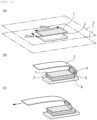
- Verfahren nach Anspruch 1, wobei das Herstellen des Elektroden-Separator-Verbundstoffs, bei dem die Elektrode (2) auf mindestens einer Oberfläche des Separators (1) gestapelt ist, und Oberflächen des Separators (1) und der Elektrode (2), die einander zugewandt sind, die Haftoberflächen und die Nicht-Haftoberflächen des Separators (1) und der Elektrode (2) umfassen, und die Haftoberflächen und die Nicht-Haftoberflächen abwechselnd angeordnet sind, Folgendes umfasst:Herstellen eines Laminats durch Stapeln der Elektrode (2) auf mindestens einer Oberfläche des Separators (1); undErwärmen und Druckbeaufschlagen nur eines Teilbereichs des Laminats, wobei der Teilbereich den Haftoberflächen des Elektroden-Separator-Verbundstoffs entspricht.
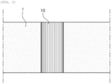
- Verfahren nach Anspruch 2, wobei das Herstellen des Laminats durch Stapeln der Elektrode (2) auf mindestens einer Oberfläche des Separators (1) und das Erwärmen und Druckbeaufschlagen nur des Teilbereichs des Laminats gleichzeitig unter Verwendung von Laminierwalzen (10, 11), die ein beabstandetes Muster umfassen, durchgeführt werden.
- Verfahren nach Anspruch 2, wobei das Erwärmen und Druckbeaufschlagen nur des Teilbereichs des Laminats den Teilbereich bei einer Temperatur von 60°C bis 120°C und einem Druck von 980,7 kPa (10 kgf/cm2) bis 9807 kPa (100 kgf/cm2) erwärmt und druckbeaufschlagt.
- Verfahren nach Anspruch 1, wobei die Haftoberfläche eine Streifenform in einer Richtung parallel zu einer Drehachse der Messwalze (14, 15) bildet.
- Verfahren nach Anspruch 1, wobei das Messen des Drehmoments, das durch die Messwalze (14, 15) erzeugt wird, während der Elektroden-Separator-Verbundstoff getrennt wird, einen Drehmomentsensor verwendet.
- Verfahren nach Anspruch 1, wobei das Messen des Drehmoments, das durch die Messwalzen (14, 15) erzeugt wird, während der Elektroden-Separator-Verbundstoff getrennt wird, Folgendes umfasst:Messen eines Drehmoments, das durch die Messwalzen (14, 15) erzeugt wird, wenn die Nicht-Haftoberflächen in dem Elektroden-Separator-Verbundstoff durch die Messwalzen (14, 15) getrennt werden;Bestimmen des Drehmoments, das gemessen wird, wenn die Nicht-Haftoberflächen durch die Messwalze (14, 15) getrennt werden, als eine Referenz für eine Nullpunkteinstellung; undMessen eines Drehmoments, das durch die Messwalzen (14, 15) erzeugt wird, wenn die Haftoberflächen in dem Elektroden-Separator-Verbundstoff durch die Messwalzen (14, 15) getrennt werden.
- Verfahren nach Anspruch 1,wobei das Erhalten einer Haftfestigkeit aus dem gemessenen Drehmoment durch Berechnen der Haftfestigkeit durch die nachstehende Gleichung 1 definiert ist:
 wobei in Gleichung 1 S eine Haftfestigkeit eines Separators (1) (Einheit: kgf; 1kgf = 9,81 N) ist, F eine Größe (Einheit: kgf·m) eines Drehmoments, das durch die Messwalzen (14, 15) erzeugt wird, während ein Elektroden-Separator-Verbundstoff getrennt wird, ist, d ein kürzester Abstand zwischen einer Elektrode (2) und einer Drehachse einer Messwalze (14, 15) (Einheit: m) ist und A ein Winkel (Einheit: rad) ist, der durch einen Elektroden-Separator-Verbundstoff und eine Elektrode (2) nach der Trennung gebildet wird.
 - Verfahren nach Anspruch 8, wobei das Erhalten der Haftfestigkeit aus dem gemessenen Drehmoment das Bewerten der Haftfestigkeit des Elektroden-Separator-Verbundstoffs aus einer Differenz zwischen der Haftfestigkeit, die durch Gleichung 1 berechnet wird, wenn die Nicht-Haftoberflächen in dem Elektroden-Separator-Verbundstoff durch die Messwalzen (14, 15) getrennt werden, und der Haftfestigkeit, die durch Gleichung 1 berechnet wird, wenn die Haftoberflächen in dem Elektroden-Separator-Verbundstoff durch die Messwalzen (14, 15) getrennt werden, ist.
Applications Claiming Priority (2)
| Application Number | Priority Date | Filing Date | Title |
|---|---|---|---|
| KR1020210160462A KR20230073753A (ko) | 2021-11-19 | 2021-11-19 | 분리막의 접착력 평가 방법 |
| PCT/KR2022/016936 WO2023090693A1 (ko) | 2021-11-19 | 2022-11-01 | 분리막의 접착력 평가 방법 |
Publications (3)
| Publication Number | Publication Date |
|---|---|
| EP4286830A1 EP4286830A1 (de) | 2023-12-06 |
| EP4286830A4 EP4286830A4 (de) | 2024-09-18 |
| EP4286830B1 true EP4286830B1 (de) | 2025-06-25 |
Family
ID=86397371
Family Applications (1)
| Application Number | Title | Priority Date | Filing Date |
|---|---|---|---|
| EP22895900.3A Active EP4286830B1 (de) | 2021-11-19 | 2022-11-01 | Verfahren zur bewertung der adhäsion eines separators |
Country Status (8)
| Country | Link |
|---|---|
| US (1) | US20240159653A1 (de) |
| EP (1) | EP4286830B1 (de) |
| JP (1) | JP7655633B2 (de) |
| KR (1) | KR20230073753A (de) |
| CN (1) | CN117063058A (de) |
| ES (1) | ES3041947T3 (de) |
| HU (1) | HUE072943T2 (de) |
| WO (1) | WO2023090693A1 (de) |
Families Citing this family (2)
| Publication number | Priority date | Publication date | Assignee | Title |
|---|---|---|---|---|
| CN118425028B (zh) * | 2024-07-03 | 2024-10-22 | 深圳铱创科技有限公司 | 阳极表面的涂层质量在线检测装置及检测方法 |
| CN118518581B (zh) * | 2024-07-23 | 2024-09-27 | 湖南新美佳鞋业股份有限公司 | 一种胶粘接拉力检测装置 |
Family Cites Families (15)
| Publication number | Priority date | Publication date | Assignee | Title |
|---|---|---|---|---|
| JPH0715438B2 (ja) * | 1986-09-27 | 1995-02-22 | 新王子製紙株式会社 | 粘着強度測定方法及び測定器 |
| JP2733133B2 (ja) * | 1990-11-13 | 1998-03-30 | 川崎製鉄株式会社 | 積層体のt字はく離強度の連続測定装置 |
| JPH07104266B2 (ja) * | 1991-04-26 | 1995-11-13 | 日本製紙株式会社 | シート状物の内部結合強度測定方法及びその測定装置 |
| JP2002005817A (ja) * | 2000-06-16 | 2002-01-09 | Mitsubishi Heavy Ind Ltd | 塗膜の密着性評価方法及び評価装置ならびに電極板の製造方法 |
| CA2373344C (en) * | 2001-02-28 | 2012-03-20 | Daido Tokushuko Kabushiki Kaisha | Corrosion-resistant metallic member, metallic separator for fuel cell comprising the same, and process for production thereof |
| JP2009210463A (ja) * | 2008-03-05 | 2009-09-17 | Bridgestone Corp | 粘着力測定装置 |
| JP2013062139A (ja) | 2011-09-13 | 2013-04-04 | Toyota Motor Corp | 電極の評価方法 |
| KR101664945B1 (ko) | 2014-08-21 | 2016-10-11 | 주식회사 엘지화학 | 전극 조립체의 제조방법 및 이를 이용하여 제조된 전극 조립체 |
| FR3028313B1 (fr) * | 2014-11-06 | 2021-01-01 | Snecma | Dispositif et procede de tests en pelage |
| CN104596923B (zh) * | 2014-12-31 | 2017-02-01 | 山东华夏神舟新材料有限公司 | 柔性基底材料涂层附着强度的测量方法 |
| KR102111105B1 (ko) * | 2016-10-10 | 2020-05-14 | 주식회사 엘지화학 | 젖음성이 향상된 이차전지용 단위 셀 및 그 제조방법 |
| CN106769845A (zh) * | 2016-12-27 | 2017-05-31 | 深圳市星源材质科技股份有限公司 | 一种聚合物涂覆锂电池隔膜与极片之间粘结力的表征方法 |
| KR102315719B1 (ko) * | 2017-04-12 | 2021-10-21 | 주식회사 엘지에너지솔루션 | 전극 합제층의 접착력이 불균일한 전극조립체 및 이의 제조 장치 |
| KR102606425B1 (ko) * | 2018-09-05 | 2023-11-27 | 주식회사 엘지에너지솔루션 | 이차 전지용 전극의 성능 예측 방법 |
| JP7338523B2 (ja) * | 2020-03-17 | 2023-09-05 | 株式会社村田製作所 | テープの剥離強度測定装置 |
-
2021
- 2021-11-19 KR KR1020210160462A patent/KR20230073753A/ko active Pending
-
2022
- 2022-11-01 WO PCT/KR2022/016936 patent/WO2023090693A1/ko not_active Ceased
- 2022-11-01 JP JP2023556839A patent/JP7655633B2/ja active Active
- 2022-11-01 HU HUE22895900A patent/HUE072943T2/hu unknown
- 2022-11-01 CN CN202280024968.0A patent/CN117063058A/zh active Pending
- 2022-11-01 ES ES22895900T patent/ES3041947T3/es active Active
- 2022-11-01 EP EP22895900.3A patent/EP4286830B1/de active Active
- 2022-11-01 US US18/282,952 patent/US20240159653A1/en active Pending
Also Published As
| Publication number | Publication date |
|---|---|
| WO2023090693A1 (ko) | 2023-05-25 |
| EP4286830A1 (de) | 2023-12-06 |
| HUE072943T2 (hu) | 2025-12-28 |
| ES3041947T3 (en) | 2025-11-17 |
| JP2024511344A (ja) | 2024-03-13 |
| US20240159653A1 (en) | 2024-05-16 |
| JP7655633B2 (ja) | 2025-04-02 |
| EP4286830A4 (de) | 2024-09-18 |
| CN117063058A (zh) | 2023-11-14 |
| KR20230073753A (ko) | 2023-05-26 |
Similar Documents
| Publication | Publication Date | Title |
|---|---|---|
| KR102303703B1 (ko) | 전고체전지 및 그 제조 방법 | |
| JP5747506B2 (ja) | 電極積層体の製造方法および電極積層体 | |
| KR101664945B1 (ko) | 전극 조립체의 제조방법 및 이를 이용하여 제조된 전극 조립체 | |
| EP4286830B1 (de) | Verfahren zur bewertung der adhäsion eines separators | |
| CN108933266B (zh) | 电池及其制造方法 | |
| US20120237825A1 (en) | Method for producing battery electrode | |
| CN114730907A (zh) | 检查方法及组电池的制造方法 | |
| JP2016072026A (ja) | 蓄電デバイスの製造装置および蓄電デバイスの製造方法 | |
| KR20220118250A (ko) | 모노셀 형태의 분리막 손상 검출 장치 및 방법 | |
| KR102913788B1 (ko) | 용접 불량 검사 방법 | |
| JP7442655B2 (ja) | 電極の圧延装置及び電極の圧延方法 | |
| EP4156360B1 (de) | Vorrichtung zur herstellung von einzelzellen mit glanzmesser und herstellungsverfahren damit | |
| KR102940139B1 (ko) | 전극 활물질 탈리 평가 방법 | |
| WO2022244759A1 (ja) | 積層シートの検査方法、積層シートの製造方法、及び、組電池の製造方法 | |
| KR20230040511A (ko) | 분리막과 전극 사이의 접착력 추산 방법 | |
| US20230134414A1 (en) | Laminator for Manufacture of Unit Structural Bodies with Increased Force of Adhesion | |
| JP2022176624A (ja) | 積層シートの検査方法、積層シートの製造方法、及び、組電池の製造方法 | |
| JP2012132855A (ja) | 電池用電極シートの検査方法及び検査装置 | |
| EP4465395A1 (de) | Sekundärbatterie mit nichtwässrigem elektrolyten | |
| EP4668386A1 (de) | Verdichtungsvorrichtung zur echtzeitüberwachung der druckkraft zur bildung einer sekundärbatterie und verdichtungsverfahren dafür | |
| KR20220136086A (ko) | 광택계가 구비된 모노셀 제조장치 및 이를 이용한 제조방법 | |
| JP2025162687A (ja) | 電池の充放電検査方法 | |
| JP2022176623A (ja) | 積層シートの検査方法、積層シートの製造方法、及び、組電池の製造方法 | |
| KR20250041790A (ko) | 배터리 셀의 평가 장치 및 이를 이용한 평가 방법 | |
| KR20250154649A (ko) | 전극의 제조방법 및 제조 시스템 |
Legal Events
| Date | Code | Title | Description |
|---|---|---|---|
| STAA | Information on the status of an ep patent application or granted ep patent |
Free format text: STATUS: THE INTERNATIONAL PUBLICATION HAS BEEN MADE |
|
| PUAI | Public reference made under article 153(3) epc to a published international application that has entered the european phase |
Free format text: ORIGINAL CODE: 0009012 |
|
| STAA | Information on the status of an ep patent application or granted ep patent |
Free format text: STATUS: REQUEST FOR EXAMINATION WAS MADE |
|
| 17P | Request for examination filed |
Effective date: 20230901 |
|
| AK | Designated contracting states |
Kind code of ref document: A1 Designated state(s): AL AT BE BG CH CY CZ DE DK EE ES FI FR GB GR HR HU IE IS IT LI LT LU LV MC ME MK MT NL NO PL PT RO RS SE SI SK SM TR |
|
| A4 | Supplementary search report drawn up and despatched |
Effective date: 20240819 |
|
| RIC1 | Information provided on ipc code assigned before grant |
Ipc: H01M 50/46 20210101ALI20240812BHEP Ipc: G01L 3/00 20060101ALI20240812BHEP Ipc: G01N 19/04 20060101AFI20240812BHEP |
|
| DAV | Request for validation of the european patent (deleted) | ||
| DAX | Request for extension of the european patent (deleted) | ||
| GRAP | Despatch of communication of intention to grant a patent |
Free format text: ORIGINAL CODE: EPIDOSNIGR1 |
|
| STAA | Information on the status of an ep patent application or granted ep patent |
Free format text: STATUS: GRANT OF PATENT IS INTENDED |
|
| INTG | Intention to grant announced |
Effective date: 20250324 |
|
| GRAS | Grant fee paid |
Free format text: ORIGINAL CODE: EPIDOSNIGR3 |
|
| GRAA | (expected) grant |
Free format text: ORIGINAL CODE: 0009210 |
|
| STAA | Information on the status of an ep patent application or granted ep patent |
Free format text: STATUS: THE PATENT HAS BEEN GRANTED |
|
| P01 | Opt-out of the competence of the unified patent court (upc) registered |
Free format text: CASE NUMBER: APP_21195/2025 Effective date: 20250505 |
|
| AK | Designated contracting states |
Kind code of ref document: B1 Designated state(s): AL AT BE BG CH CY CZ DE DK EE ES FI FR GB GR HR HU IE IS IT LI LT LU LV MC ME MK MT NL NO PL PT RO RS SE SI SK SM TR |
|
| REG | Reference to a national code |
Ref country code: GB Ref legal event code: FG4D |
|
| REG | Reference to a national code |
Ref country code: CH Ref legal event code: EP |
|
| REG | Reference to a national code |
Ref country code: CH Ref legal event code: EP |
|
| REG | Reference to a national code |
Ref country code: IE Ref legal event code: FG4D |
|
| REG | Reference to a national code |
Ref country code: DE Ref legal event code: R096 Ref document number: 602022016630 Country of ref document: DE |
|
| PG25 | Lapsed in a contracting state [announced via postgrant information from national office to epo] |
Ref country code: FI Free format text: LAPSE BECAUSE OF FAILURE TO SUBMIT A TRANSLATION OF THE DESCRIPTION OR TO PAY THE FEE WITHIN THE PRESCRIBED TIME-LIMIT Effective date: 20250625 |
|
| REG | Reference to a national code |
Ref country code: LT Ref legal event code: MG9D |
|
| PG25 | Lapsed in a contracting state [announced via postgrant information from national office to epo] |
Ref country code: GR Free format text: LAPSE BECAUSE OF FAILURE TO SUBMIT A TRANSLATION OF THE DESCRIPTION OR TO PAY THE FEE WITHIN THE PRESCRIBED TIME-LIMIT Effective date: 20250926 Ref country code: NO Free format text: LAPSE BECAUSE OF FAILURE TO SUBMIT A TRANSLATION OF THE DESCRIPTION OR TO PAY THE FEE WITHIN THE PRESCRIBED TIME-LIMIT Effective date: 20250925 |
|
| PG25 | Lapsed in a contracting state [announced via postgrant information from national office to epo] |
Ref country code: BG Free format text: LAPSE BECAUSE OF FAILURE TO SUBMIT A TRANSLATION OF THE DESCRIPTION OR TO PAY THE FEE WITHIN THE PRESCRIBED TIME-LIMIT Effective date: 20250625 |
|
| PG25 | Lapsed in a contracting state [announced via postgrant information from national office to epo] |
Ref country code: HR Free format text: LAPSE BECAUSE OF FAILURE TO SUBMIT A TRANSLATION OF THE DESCRIPTION OR TO PAY THE FEE WITHIN THE PRESCRIBED TIME-LIMIT Effective date: 20250625 |
|
| PG25 | Lapsed in a contracting state [announced via postgrant information from national office to epo] |
Ref country code: RS Free format text: LAPSE BECAUSE OF FAILURE TO SUBMIT A TRANSLATION OF THE DESCRIPTION OR TO PAY THE FEE WITHIN THE PRESCRIBED TIME-LIMIT Effective date: 20250925 |
|
| PG25 | Lapsed in a contracting state [announced via postgrant information from national office to epo] |
Ref country code: LV Free format text: LAPSE BECAUSE OF FAILURE TO SUBMIT A TRANSLATION OF THE DESCRIPTION OR TO PAY THE FEE WITHIN THE PRESCRIBED TIME-LIMIT Effective date: 20250625 |
|
| REG | Reference to a national code |
Ref country code: NL Ref legal event code: MP Effective date: 20250625 |
|
| PG25 | Lapsed in a contracting state [announced via postgrant information from national office to epo] |
Ref country code: NL Free format text: LAPSE BECAUSE OF FAILURE TO SUBMIT A TRANSLATION OF THE DESCRIPTION OR TO PAY THE FEE WITHIN THE PRESCRIBED TIME-LIMIT Effective date: 20250625 |
|
| REG | Reference to a national code |
Ref country code: ES Ref legal event code: FG2A Ref document number: 3041947 Country of ref document: ES Kind code of ref document: T3 Effective date: 20251117 |
|
| PG25 | Lapsed in a contracting state [announced via postgrant information from national office to epo] |
Ref country code: PT Free format text: LAPSE BECAUSE OF FAILURE TO SUBMIT A TRANSLATION OF THE DESCRIPTION OR TO PAY THE FEE WITHIN THE PRESCRIBED TIME-LIMIT Effective date: 20251027 |
|
| PGFP | Annual fee paid to national office [announced via postgrant information from national office to epo] |
Ref country code: HU Payment date: 20251127 Year of fee payment: 4 |
|
| REG | Reference to a national code |
Ref country code: AT Ref legal event code: MK05 Ref document number: 1806904 Country of ref document: AT Kind code of ref document: T Effective date: 20250625 |
|
| REG | Reference to a national code |
Ref country code: HU Ref legal event code: AG4A Ref document number: E072943 Country of ref document: HU |
|
| PG25 | Lapsed in a contracting state [announced via postgrant information from national office to epo] |
Ref country code: IS Free format text: LAPSE BECAUSE OF FAILURE TO SUBMIT A TRANSLATION OF THE DESCRIPTION OR TO PAY THE FEE WITHIN THE PRESCRIBED TIME-LIMIT Effective date: 20251025 |
|
| PGFP | Annual fee paid to national office [announced via postgrant information from national office to epo] |
Ref country code: DE Payment date: 20251020 Year of fee payment: 4 |
|
| PG25 | Lapsed in a contracting state [announced via postgrant information from national office to epo] |
Ref country code: AT Free format text: LAPSE BECAUSE OF FAILURE TO SUBMIT A TRANSLATION OF THE DESCRIPTION OR TO PAY THE FEE WITHIN THE PRESCRIBED TIME-LIMIT Effective date: 20250625 Ref country code: SM Free format text: LAPSE BECAUSE OF FAILURE TO SUBMIT A TRANSLATION OF THE DESCRIPTION OR TO PAY THE FEE WITHIN THE PRESCRIBED TIME-LIMIT Effective date: 20250625 |
|
| PGFP | Annual fee paid to national office [announced via postgrant information from national office to epo] |
Ref country code: FR Payment date: 20251021 Year of fee payment: 4 |
|
| PGFP | Annual fee paid to national office [announced via postgrant information from national office to epo] |
Ref country code: BE Payment date: 20251020 Year of fee payment: 4 |
|
| PG25 | Lapsed in a contracting state [announced via postgrant information from national office to epo] |
Ref country code: CZ Free format text: LAPSE BECAUSE OF FAILURE TO SUBMIT A TRANSLATION OF THE DESCRIPTION OR TO PAY THE FEE WITHIN THE PRESCRIBED TIME-LIMIT Effective date: 20250625 |
|
| PG25 | Lapsed in a contracting state [announced via postgrant information from national office to epo] |
Ref country code: PL Free format text: LAPSE BECAUSE OF FAILURE TO SUBMIT A TRANSLATION OF THE DESCRIPTION OR TO PAY THE FEE WITHIN THE PRESCRIBED TIME-LIMIT Effective date: 20250625 |
|
| PG25 | Lapsed in a contracting state [announced via postgrant information from national office to epo] |
Ref country code: EE Free format text: LAPSE BECAUSE OF FAILURE TO SUBMIT A TRANSLATION OF THE DESCRIPTION OR TO PAY THE FEE WITHIN THE PRESCRIBED TIME-LIMIT Effective date: 20250625 |
|
| PG25 | Lapsed in a contracting state [announced via postgrant information from national office to epo] |
Ref country code: SK Free format text: LAPSE BECAUSE OF FAILURE TO SUBMIT A TRANSLATION OF THE DESCRIPTION OR TO PAY THE FEE WITHIN THE PRESCRIBED TIME-LIMIT Effective date: 20250625 |
|
| PGFP | Annual fee paid to national office [announced via postgrant information from national office to epo] |
Ref country code: ES Payment date: 20251215 Year of fee payment: 4 |
|
| PG25 | Lapsed in a contracting state [announced via postgrant information from national office to epo] |
Ref country code: RO Free format text: LAPSE BECAUSE OF FAILURE TO SUBMIT A TRANSLATION OF THE DESCRIPTION OR TO PAY THE FEE WITHIN THE PRESCRIBED TIME-LIMIT Effective date: 20250625 |
|
| PG25 | Lapsed in a contracting state [announced via postgrant information from national office to epo] |
Ref country code: DK Free format text: LAPSE BECAUSE OF FAILURE TO SUBMIT A TRANSLATION OF THE DESCRIPTION OR TO PAY THE FEE WITHIN THE PRESCRIBED TIME-LIMIT Effective date: 20250625 |
|
| PG25 | Lapsed in a contracting state [announced via postgrant information from national office to epo] |
Ref country code: IT Free format text: LAPSE BECAUSE OF FAILURE TO SUBMIT A TRANSLATION OF THE DESCRIPTION OR TO PAY THE FEE WITHIN THE PRESCRIBED TIME-LIMIT Effective date: 20250625 |
|
| PLBE | No opposition filed within time limit |
Free format text: ORIGINAL CODE: 0009261 |
|
| STAA | Information on the status of an ep patent application or granted ep patent |
Free format text: STATUS: NO OPPOSITION FILED WITHIN TIME LIMIT |