EP4286830B1 - Method for evaluating adhesion of separator - Google Patents
Method for evaluating adhesion of separator Download PDFInfo
- Publication number
- EP4286830B1 EP4286830B1 EP22895900.3A EP22895900A EP4286830B1 EP 4286830 B1 EP4286830 B1 EP 4286830B1 EP 22895900 A EP22895900 A EP 22895900A EP 4286830 B1 EP4286830 B1 EP 4286830B1
- Authority
- EP
- European Patent Office
- Prior art keywords
- electrode
- separator
- measuring
- composite
- adhesive
- Prior art date
- Legal status (The legal status is an assumption and is not a legal conclusion. Google has not performed a legal analysis and makes no representation as to the accuracy of the status listed.)
- Active
Links
Images


Classifications
-
- G—PHYSICS
- G01—MEASURING; TESTING
- G01L—MEASURING FORCE, STRESS, TORQUE, WORK, MECHANICAL POWER, MECHANICAL EFFICIENCY, OR FLUID PRESSURE
- G01L5/00—Apparatus for, or methods of, measuring force, work, mechanical power, or torque, specially adapted for specific purposes
- G01L5/0028—Force sensors associated with force applying means
- G01L5/0042—Force sensors associated with force applying means applying a torque
-
- G—PHYSICS
- G01—MEASURING; TESTING
- G01L—MEASURING FORCE, STRESS, TORQUE, WORK, MECHANICAL POWER, MECHANICAL EFFICIENCY, OR FLUID PRESSURE
- G01L3/00—Measuring torque, work, mechanical power, or mechanical efficiency, in general
-
- G—PHYSICS
- G01—MEASURING; TESTING
- G01N—INVESTIGATING OR ANALYSING MATERIALS BY DETERMINING THEIR CHEMICAL OR PHYSICAL PROPERTIES
- G01N19/00—Investigating materials by mechanical methods
- G01N19/04—Measuring adhesive force between materials, e.g. of sealing tape, of coating
-
- H—ELECTRICITY
- H01—ELECTRIC ELEMENTS
- H01M—PROCESSES OR MEANS, e.g. BATTERIES, FOR THE DIRECT CONVERSION OF CHEMICAL ENERGY INTO ELECTRICAL ENERGY
- H01M10/00—Secondary cells; Manufacture thereof
- H01M10/04—Construction or manufacture in general
-
- H—ELECTRICITY
- H01—ELECTRIC ELEMENTS
- H01M—PROCESSES OR MEANS, e.g. BATTERIES, FOR THE DIRECT CONVERSION OF CHEMICAL ENERGY INTO ELECTRICAL ENERGY
- H01M50/00—Constructional details or processes of manufacture of the non-active parts of electrochemical cells other than fuel cells, e.g. hybrid cells
- H01M50/40—Separators; Membranes; Diaphragms; Spacing elements inside cells
- H01M50/46—Separators, membranes or diaphragms characterised by their combination with electrodes
-
- Y—GENERAL TAGGING OF NEW TECHNOLOGICAL DEVELOPMENTS; GENERAL TAGGING OF CROSS-SECTIONAL TECHNOLOGIES SPANNING OVER SEVERAL SECTIONS OF THE IPC; TECHNICAL SUBJECTS COVERED BY FORMER USPC CROSS-REFERENCE ART COLLECTIONS [XRACs] AND DIGESTS
- Y02—TECHNOLOGIES OR APPLICATIONS FOR MITIGATION OR ADAPTATION AGAINST CLIMATE CHANGE
- Y02E—REDUCTION OF GREENHOUSE GAS [GHG] EMISSIONS, RELATED TO ENERGY GENERATION, TRANSMISSION OR DISTRIBUTION
- Y02E60/00—Enabling technologies; Technologies with a potential or indirect contribution to GHG emissions mitigation
- Y02E60/10—Energy storage using batteries
-
- Y—GENERAL TAGGING OF NEW TECHNOLOGICAL DEVELOPMENTS; GENERAL TAGGING OF CROSS-SECTIONAL TECHNOLOGIES SPANNING OVER SEVERAL SECTIONS OF THE IPC; TECHNICAL SUBJECTS COVERED BY FORMER USPC CROSS-REFERENCE ART COLLECTIONS [XRACs] AND DIGESTS
- Y02—TECHNOLOGIES OR APPLICATIONS FOR MITIGATION OR ADAPTATION AGAINST CLIMATE CHANGE
- Y02P—CLIMATE CHANGE MITIGATION TECHNOLOGIES IN THE PRODUCTION OR PROCESSING OF GOODS
- Y02P70/00—Climate change mitigation technologies in the production process for final industrial or consumer products
- Y02P70/50—Manufacturing or production processes characterised by the final manufactured product
Definitions
- the secondary batteries may be divided into a nickel-cadmium battery, a nickel-metal hydride battery, a nickel-hydrogen battery, and a lithium secondary battery.
- the lithium secondary battery has a higher operating voltage than the nickel-cadmium battery or nickel-metal hydride battery, and have an excellent characteristics of energy density per unit weight, such that they are mainly used in portable electronic devices or high-output hybrid vehicles.
- the term 'adhesive surface' means a portion in which the adhesion is made, and the term "non-adhesive surface' means a portion in which the adhesion is not made.
- the distance between the adhesive surfaces may be the same.
- the manufacturing of the laminate by stacking the electrode on at least one surface of the separator and the heating and pressurizing of only the partial region of the laminate may be performed simultaneously using a lamination roll including a spaced pattern.
- the separator may be a safety reinforced separator (SRS) including a non-aqueous binder on a surface thereof.
- SRS safety reinforced separator
- the positive electrode may be a positive electrode sheet
- the negative electrode may be a negative electrode sheet.
- the electrode sheet may have a shape of an electrode plate of a specific or predetermined size by the cutting of the electrode-separator composite.
- the positive electrode and the positive electrode sheet may be manufactured by a method for manufacturing the positive electrode sheet using the positive electrode active material which is well known in the art, for example, by a method in which the positive electrode sheet is mixed with a binder or the like to manufacture a positive electrode slurry and the manufactured positive electrode slurry is applied, rolled, and dried on a positive electrode current collector.
- the positive electrode active material is not particularly limited if it is generally used for the positive electrode of the secondary battery in the art, but for example, lithium metal oxide (LiMO 2 ) in a layered structure such as lithium cobaltate (LiCoO 2 ) and a triatomic system, spinel material (LiM 2 O 4 ) represented by lithium manganese oxide (LiM 2 O 4 ), or olivine-based material (LiMPO 4 ) such as lithium iron phosphate (LiFePO 4 ) may be used.
- lithium metal oxide (LiMO 2 ) in a layered structure such as lithium cobaltate (LiCoO 2 ) and a triatomic system, spinel material (LiM 2 O 4 ) represented by lithium manganese oxide (LiM 2 O 4 ), or olivine-based material (LiMPO 4 ) such as lithium iron phosphate (LiFePO 4 ) may be used.
- aluminum may be used as the positive electrode current collector.
- the negative electrode and the negative electrode sheet may be manufactured by a method for manufacturing the negative electrode sheet using the negative electrode active material which is well known in the art, for example, by a method in which the negative electrode sheet is mixed with a binder or the like to manufacture a negative electrode slurry and the manufactured positive electrode slurry is subsequently applied, rolled, and dried on a negative electrode current collector.
- the negative electrode active material is not particularly limited if it is generally used for the negative electrode of the secondary battery in the art, but for example, a carbon (C) based material, Si, Sn, tin oxide, composite tin alloys, transition metal oxide or lithium metal oxide, and the like may be used.
- a carbon (C) based material Si, Sn, tin oxide, composite tin alloys, transition metal oxide or lithium metal oxide, and the like may be used.
- copper or nickel may be used as the negative electrode current collector.
- the binder is for improving the adhering force between the positive or negative active materials
- those well known in the art may be used without limitation, for example, polyvinylidene fluoride (PVDF), polytetrafluoroethylene (PTFE), cellulose, polyvinyl alcohol, carboxymethylcellulose (CMC), starch, hydroxypropyl cellulose, regenerated cellulose, polyvinylpyrrolidone, tetrafluoroethylene, polyethylene, polypropylene, EPDM rubber, sulfonated EPDM or styrene butadiene rubber (SBR) and the like may be used, but not limited thereto.
- PVDF polyvinylidene fluoride
- PTFE polytetrafluoroethylene
- CMC carboxymethylcellulose
- SBR styrene butadiene rubber
- the positive electrode slurry or negative electrode slurry may further include a conductive material or a filler. Materials commonly used in the art may be used as the conductive material and the filler.
- carbon black such as Denka black, acetylene black, Ketjen black, furnace black, thermal black, etc., one or more types selected from a group consisting of natural graphite and artificial graphite may be used as the conductive material, but the conductive material is not limited thereto, and the conductive material which has conductivity without causing chemical changes in the constituted battery may be generally used.
- one or more types selected from a group consisting of polyethylene, polypropylene, glass fiber, and carbon fiber may be used as the filler, but is not limited thereto, and a fibrous material which does not cause chemical changes in the constituted battery may be generally used as the filler.
- a thickness of the positive electrode is 50 ⁇ m to 300 ⁇ m, preferably 100 ⁇ m to 200 ⁇ m,but not limited thereto.
- a thickness of the negative electrode is 50 ⁇ m to 300 ⁇ m, preferably 100 ⁇ m to 200 ⁇ m,but not limited thereto.
- the thickness of the negative electrode is thicker than that of the positive electrode.
- the thickness of the electrode may be measured by scanning a cross-section of the electrode using a Scanning Electron Microscope (SEM).
- the thickness of the electrode means the thickness including both the electrode current collector and the electrode active material layer.
- an olefin-based polymer a sheet, a non-woven fabric, and kraft paper made of glass fiber, polyethylene, or the like may be used as the separator, and the olefin-based polymer may be preferably used.
- one or more types selected from a group consisting of high density polyethylene, low density polyethylene, linear low density polyethylene, ultra-high molecular weight polyethylene, polypropylene, polyethyleneterephthalate, polybutyleneterephthalate, polyester, polyacetal, polyamide, polycarbonate, polyimide, polyetheretherketone, polyethersulfone, polyphenyleneoxide, polyphenylenesulfidro, polyethylenenaphthalene and mixtures thereof may be used as the separator, but not limited thereto.
- the thickness of the separator may be measured by scanning a cross-section of the separator using SEM.
- the cutting of the electrode-separator composite may be performed by a cutting roll.
- FIG. 4 is a top plan view illustrating a cutting process of the method for evaluating the adhesive strength of the separator according to the present disclosure. While the separator 1 and the electrode 2 are supplied between the cutting rolls 12 and 13, the electrode is stacked on at least one surface of the separator, heated and pressurized, and subsequently the electrode-separator composite in which the adhesive and non-adhesive surfaces of the separator and electrode are alternately disposed passes through the cutting rolls, the electrode-separator composite may be cut in a direction parallel to the moving direction (the adhesive and non-adhesive surfaces and some configurations are not illustrated).
- a distance between the cut portions in the cutting of the electrode-separator composite in the direction parallel to the moving direction may be equal.
- a distance between portions which is cut in the cutting of the electrode-separator composite in the direction parallel to the moving direction may be different.
- the 'cutting roll' is a device for cutting the electrode-separator composite.
- the moving of the electrode-separator composite may be performed by a conveyor belt, but not limited thereto, all means for moving the electrode-separator composite in a predetermined direction may be used.
- the direction in which the electrode-separator composite is moved may be referred to as a 'manufacturing direction'. That is, the cutting of the electrode-separator composite in the direction parallel to the moving direction means that the cutting of the electrode-separator composite cuts the electrode-separator composite at a predetermined interval parallel to the manufacturing direction (MD).
- MD manufacturing direction
- the cutting of the electrode-separator composite in the direction parallel to the moving direction may be cutting the electrode-separator composite at a predetermined interval.
- the attaching of the measuring rolls to each of the two surfaces of the cut electrode-separator composite means that the measuring rolls are in contact with each of both surfaces of the electrode-separator composite so that a predetermined force may be applied to both surfaces of the cut electrode-separator composite.
- FIG. 5 is a top plan view of a measurement process of the method for evaluating the adhesive strength of the separator according to the present disclosure.
- the measuring rolls 14 and 15 are attached to the electrode-separator composite which is cut in the direction parallel to the moving direction by the cutting rolls 12 and 13, and the evaluation of the adhesive strength of the separator is performed as described below (adhesive and non-adhesive surfaces and some configurations are not illustrated).
- the measuring of the torque generated by the measuring rolls while separating the electrode-separator composite may use a torque sensor.
- the measuring of the torque generated by the measuring rolls while separating the electrode-separator composite may include: measuring a torque generated by the measuring rolls when the non-adhesive surfaces in the electrode-separator composite are separated by the measuring rolls; determining the torque measured when the non-adhesive surfaces are separated by the measuring rolls as a reference for zero-point adjustment; and measuring a torque generated by the measuring rolls when the adhesive surfaces in the electrode-separator composite are separated by the measuring rolls.
- the torque measured when portions (non-adhesive surfaces) in which the adhesive strength is not made in the electrode-composite are separated (or opened) is set to zero-point, and thereafter, the torque when portions in which the adhesive strength is made (adhesive surfaces) are separated (or opened) may be measured.
- the adhesive strength of the electrode-separator composite may be expressed as a specific value from the measured torque value, thereby evaluating the adhesive strength.
- obtaining the adhesive strength from the measured torque is defined by calculating the adhesive strength by equation 1 below.
- S F / d ⁇ sin A
- a magnitude of the torque generated by the measuring rolls while separating the electrode-separator composite means a value measuring a torque generated by the measuring rolls using a torque sensor or the like. That is, it means a torque measured by the measuring rolls.
- sin means trigonometric function
- sin A means the sin value of angle A (unit: radian).
- the method for evaluating the adhesive strength of the separator according to the exemplary embodiment of the present disclosure may be performed by a roll-to-roll process. Therefore, the evaluation of the adhesive strength may be performed at one time by a continuous process.
- the torque measured when the portions (non-adhesive surfaces) in which the adhesive strength is not made are separated (or opened) is set to zero-point, and thereafter, the torque when the portions in which the adhesive strength is made (adhesive surfaces) are separated (or opened) may be measured, thereby, evaluating the adhesive strength of the electrode-separator composite. More specifically, the adhesive strength is evaluated from the value of the difference between the adhesive strength calculated by Equation 1 when the non-adhesive surfaces in the electrode-separator composite are separated by the measuring rolls and the adhesive strength calculated by Equation 1 when the adhesive surfaces in the electrode-separator composite are separated by the measuring rolls. In this case, the process from the deformation by the measuring rolls 14 and 15 to the evaluation of the adhesive strength is defined as a measurement process.
- the cutting rolls 12, 13, and measuring rolls may be applied in one or more pairs.
- the electrode-separator composite may be divided into three pieces by cutting the electrode-separator composite to have a predetermined interval by a pair of cutting rolls 12 and 13, and the measuring rolls 14 and 15 may be attached to each of the electrode-separator composites, thereby applying the evaluation of the adhesive strength. That is, three pairs of measuring rolls 14-1, 15-1, 14-2, 15-2, 14-3, and 15-3 may be used.
- ZD corresponds to a thickness direction of material in a facility
- MD means a direction parallel to the moving direction of material in the facility, that is, the manufacturing direction
- CD means a direction parallel to a width direction of material in the facility and perpendicular to the MD.
- the electrode 2 is stacked on at least one surface of the separator 1, and surfaces of the separator and the electrode facing each other include the adhesive surfaces and non-adhesive surfaces of the separator and electrode, and when the electrode-separator composite in which the adhesive and non-adhesive surfaces of the separator 1 and electrode 2 are alternately disposed is separated by the measuring rolls 14 and 15, the torque sensed in the measuring roll 15 to which the electrode is attached by the torque sensor (not illustrated) is recorded in real time.
- the angle A formed by the electrode-separator composite and the electrode after separation is also recorded by a computer vision system (not illustrated).
- the value measured from the record may be substituted into Equation 1 to obtain the adhesive strength of the separator in real time. That is, it is possible to continuously perform the evaluation of the adhesive strength of the separator at various positions of the electrode-separator composite. Therefore, according to the exemplary embodiment of the method for evaluating the adhesive strength of the separator of the present application, it is possible to obtain an advantageous effect of reducing the time required for the evaluation, reducing the possibility of defects occurring in the process, and also efficiently controlling the process.
Landscapes
- Chemical & Material Sciences (AREA)
- Physics & Mathematics (AREA)
- General Physics & Mathematics (AREA)
- Chemical Kinetics & Catalysis (AREA)
- Electrochemistry (AREA)
- General Chemical & Material Sciences (AREA)
- Analytical Chemistry (AREA)
- Health & Medical Sciences (AREA)
- Life Sciences & Earth Sciences (AREA)
- Biochemistry (AREA)
- General Health & Medical Sciences (AREA)
- Immunology (AREA)
- Pathology (AREA)
- Manufacturing & Machinery (AREA)
- Engineering & Computer Science (AREA)
- Secondary Cells (AREA)
- Cell Separators (AREA)
- Battery Electrode And Active Subsutance (AREA)
Description
- The present application relates to a method for evaluating an adhesive strength of a separator.
- The demand for secondary batteries such as electric vehicles and mobile devices is rapidly expanding, and there is an increasing need for the condition diagnosis and the quality stability of the secondary batteries.
- The secondary batteries may be divided into a nickel-cadmium battery, a nickel-metal hydride battery, a nickel-hydrogen battery, and a lithium secondary battery. Among the above-described secondary batteries, the lithium secondary battery has a higher operating voltage than the nickel-cadmium battery or nickel-metal hydride battery, and have an excellent characteristics of energy density per unit weight, such that they are mainly used in portable electronic devices or high-output hybrid vehicles.
- In general, the lithium secondary battery may include an electrode assembly having a positive electrode, a negative electrode, and a separator, electrode tabs extending from the electrode assembly, and electrode leads welded to the electrode tabs. In this case, the electrode assembly is a power generating element in which positive and negative electrodes are stacked with the separator interposed therebetween. In general, the electrode assembly is manufactured using a method in which the negative electrode, separator, and positive electrode are respectively manufactured in a separate process, and then laminated and adhered by applying heat and pressure at the same time. However, in the case of a high-capacity battery, the separator containing a less binder, that is, the thin separator with a low binder content, is often applied. For this reason, when the battery is manufactured in the above-mentioned method, there is a problem in that a sufficient adhesive strength is not secured between the electrode and the separator.
- Therefore, it is important to use the separator with an excellent adhesive strength to secure a sufficient adhesive strength. To this end, it is important to evaluate the adhesive strength of the separator. In the related art, as illustrated in
FIG. 2 , in order to evaluate the adhesive strength of the separator, a method for evaluating the adhesive strength in which a specimen of the separator and electrode manufactured by applying heat and pressure is prepared and a peel test is performed on the manufactured specimen is generally used. - Specifically, the peel test is performed as illustrated in
FIG. 2 . Aseparator 1 with a width of 25 mm and a length of 60 mm and anelectrode 2 are stacked, placed between a polyethylene terephthalate (PET) film 3, and pressed with a heated press. Thereby, an electrode-separator composite in which an adhesive strength is generated between the separator and the electrode is manufactured (FIG. 2A ). Aslide glass 6 is attached using a double-sided adhesive tape 5 to an electrode surface of the electrode-separator composite manufactured as described above, and the PET film is attached using a single-sidedadhesive tape 4 to a partial region of a separator surface of the electrode-separator composite, resulting in manufacturing the specimen (FIG. 2B ). The specimen manufactured as described above is mounted on a universal material testing machine and a force required to separate the separator and the electrode is measured (FIG. 2C ). - In this case, since the adhesive strength of the separator greatly fluctuates depending on a position, it is necessary to evaluate the adhesive strength by attaching the PET film to various positions on the separator surface of the electrode-separator composite. However, it takes a large amount of time to make several specimens and measure each one. Because of the above-mentioned restriction, there is a problem in that the evaluation (sampling inspection) of the adhesive strength of the separator is not sufficiently achieved.
- Therefore, there is a need for a new method for evaluating an adhesive strength of a separator which is capable of overcoming the above-described problem.
-
Korean Patent Publication No. 10-2016-0023072 JP 2013-62139 A - The present application has been made in an effort to provide a method capable of efficiently performing an evaluation of an adhesive strength of a separator over a large region.
- The present disclosure provides a method for evaluating an adhesive strength of a separator, the method including: manufacturing an electrode-separator composite in which an electrode is stacked on at least one surface of a separator, and surfaces of the separator and the electrode facing each other include adhesive surfaces and non-adhesive surfaces of the separator and the electrode, and the adhesive surfaces and the non-adhesive surfaces are alternately disposed; moving the electrode-separator composite; cutting the electrode-separator composite in a direction parallel to the moving direction; attaching measuring rolls respectively to both surfaces of the cut electrode-separator composite; separating the electrode-separator composite by rotating each of the attached measuring rolls and spacing the measuring rolls apart from each other; and measuring a torque generated by the measuring rolls while separating the electrode-separator composite, and obtaining an adhesive strength from the measured torque.
- Further embodiments are disclosed in the dependent claims.
- A method for evaluating an adhesive strength of a separator according to the present application may reduce the time required for the evaluation.
- A method for evaluating an adhesive strength of a separator according to the present application may continuously evaluate the adhesive strength of the separator, thereby reducing the possibility of occurring failure in the process.
- A method for evaluating an adhesive strength of a separator according to the present application may often and easily perform the evaluation, thereby efficiently controlling the process.
-
-
FIG. 1 is a side view illustrating an exemplary embodiment of a method for evaluating of an adhesive strength of a separator according to the present application. -
FIG. 2 is a view illustrating an embodiment of a method for evaluating an adhesive strength of a separator in the related art. -
FIG. 3 is a top plan view illustrating a lamination process according to the method for evaluating the adhesive strength of the separator of the present application. -
FIG. 4 is a top plan view illustrating a cutting process according to the method for evaluating the adhesive strength of the separator of the present application. -
FIG. 5 is a top plan view illustrating a measurement process according to the method for evaluating the adhesive strength of the separator of the present application. -
FIG. 6 is an enlarged view illustrating the measurement process according to the exemplary embodiment of the method for evaluating the adhesive strength of the separator of the present application. -
- 1: Separator
- 2: Electrode
- 3: PET film
- 4: Single-sided adhesive tape
- 5: Double-sided adhesive tape
- 6: Slide glass
- 10, 11: Lamination roll
- 12, 13: Cutting roll
- 14(14-1, 14-2, 14-3), 15(15-1, 15-2, 15-3): Measuring roll
- a: Fixed portion
- Hereinafter, exemplary embodiments of the present disclosure will be described in detail so that those with ordinary skill in the art to which the present disclosure pertains may easily carry out the exemplary embodiments.
- Throughout the specification, unless explicitly described to the contrary, the word "comprise" or "include" and variations, such as "comprises," "comprising," "includes," or "including", means the further inclusion of stated constituent elements, not the exclusion of any other constituent elements.
- In the present specification, the term 'adhesion' means a method of respectively manufacturing a negative electrode, a separator, and a positive electrode in a separate process, and then stacking the separator and the negative electrode and/or positive electrode, and simultaneously applying heat and pressure. The term 'adhesion' is also called a 'lamination'.
- In the present specification, the term 'adhesive surface' means a portion in which the adhesion is made, and the term "non-adhesive surface' means a portion in which the adhesion is not made.
- A method for evaluating an adhesive strength of a separator according to the present disclosure includes: manufacturing an electrode-separator composite in which an electrode is stacked on at least one surface of a separator, and surfaces of the separator and the electrode facing each other include an adhesive surface and a non-adhesive surface of the separator and the electrode, and the adhesive surface and the non-adhesive surface are alternately disposed; moving the electrode-separator composite; cutting the electrode-separator composite in a direction parallel to the moving direction; attaching measuring rolls respectively to both surfaces of the cut electrode-separator composite; separating the electrode-separator composite by rotating each of the attached measuring rolls and spacing the measuring rolls apart from each other; and measuring a torque generated by the measuring rolls while separating the electrode-separator composite, and obtaining an adhesive strength from the measured torque.
- In the exemplary embodiment of the present disclosure, the manufacturing of the electrode-separator composite in which the electrode is stacked on at least one surface of the separator, and the surfaces of the separator and the electrode facing each other include the adhesive surface and the non-adhesive surface of the separator and the electrode, and the adhesive surface and the non-adhesive surface are alternately disposed, may include: manufacturing a laminate by stacking the electrode on at least one surface of the separator; and heating and pressurizing only a partial region of the laminate, in which the partial region may correspond to the adhesive surface of the electrode-separator composite.
- That is, the heating and pressurizing of only the partial region of the laminate corresponding to the adhesive surface of the electrode-separator composite may heat and pressurize the partial region so that the adhesive surface is formed at a predetermined interval.
- In the present specification, the 'predetermined interval' means that a distance from one specific position to another specific position is not only the same, but also different from each other.
- In the present specification, the 'distance' means the shortest length from one specific position to another specific position.
- In the exemplary embodiment of the present disclosure, the distance between the adhesive surfaces may be the same.
- In the exemplary embodiment of the present disclosure, the distance between the adhesive surfaces may be different.
- In the exemplary embodiment of the present disclosure, the manufacturing of the laminate by stacking the electrode on at least one surface of the separator and the heating and pressurizing of only the partial region of the laminate may be performed simultaneously using a lamination roll including a spaced pattern.
- In the exemplary embodiment of the present disclosure, the adhesive surface may be formed in a stripe shape in a direction parallel to a rotating axis of the measuring roll.
- In the present specification, the 'lamination roll' is a device for manufacturing the electrode-separator composite by adhering the separator to at least one surface of the electrode, and while the separator and the electrode are passing through the lamination roll, laminating, heating, and pressurizing of the separator and the electrode may be simultaneously performed to manufacture the electrode-separator composite.
- More specifically, the lamination roll may have a pattern with a predetermined interval, and while the separator and electrode pass through the two lamination rolls, laminating, heating, and pressurizing of the separator and electrode may be performed simultaneously, such that the separator and electrode may be adhered. In this case, only a portion corresponding to a region having the pattern may be heated and pressurized to manufacture the electrode-separator composite in which the adhesive and non-adhesive surfaces of the separator and electrode are alternately disposed.
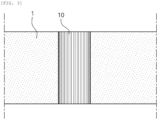
- In this regard,
FIG. 3 is a top plane view illustrating a lamination process for the method for evaluating the adhesive strength of the separator according to the present disclosure. While theseparator 1 and theelectrode 2 are supplied between lamination rolls 10 and 11, the electrode is stacked on at least one surface of the separator, heated and pressurized to form the electrode-separator composite in which the adhesive and non-adhesive surfaces of the separator and electrode are alternately disposed. The adhesive and non-adhesive surfaces may be formed alternately in accordance with a shape of the pattern formed in the lamination rolls (the adhesive and non-adhesive surfaces and some configurations are not illustrated). - By the above-described process, the adhesive and non-adhesive surfaces are alternatively disposed in the electrode-separator composite, in which the adhesive surfaces of the separator and electrode are adhered in a stripe shape in a direction parallel to the rotating axis of the measuring roll, which is defined herein as 'pattern lamination' in the present specification.
- That is, in the present specification, the adhesive surfaces of the separator and electrode are adhered so as to form a stripe shape in a direction parallel to the rotating axis of the measuring roll, which may be defined herein as the pattern lamination.
- When the electrode-separator composite is manufactured by the pattern lamination, the electrode-separator composite having a plurality of adhesive surfaces at a predetermined interval may be manufactured. Therefore, a torque measured when a portion (non-adhesive surfaces) where the adhesive strength is not made is opened may be used as the basis for zero-point adjustment, such that there is an advantage that the measuring of the adhesive strength of the separator may be often performed.
- In the exemplary embodiment of the present disclosure, the heating and pressurizing of only the partial region of the laminate may heat and pressurize the partial region of the laminate at a temperature of 60 °C to 120 °C and a pressure of 980.7 kPa (10 kgf/cm2) to 9807 kPa (100 kgf/cm2). Preferably, the heating and pressurizing of only the partial region of the laminate may heat and pressurize the partial region of the laminate at a temperature of 70 °C to 110 °C and a pressure of 1961.4 kPa (20 kgf /cm2) to 7845.6 kPa (80 kgf /cm2) .
- In the exemplary embodiment of the present disclosure, the heating may be performed at a temperature of 60 °C to 120 °C, preferably 70 °C. to 110 °C.
- In the exemplary embodiment of the present disclosure, the pressurizing may be performed at a pressure of 980.7 kPa (10 kgf/cm2) to 9807 kPa (100 kgf/cm2), preferably at a pressure of 1961.4 kPa (20 kgf/cm2) to 7845.6 kPa (80 kgf/cm2) .
- When the above-described temperature and pressure conditions are satisfied, the separator may be prevented from being deformed due to heat or pressure, thereby enabling a stable adhesion.
- In the present specification, the 'measuring roll' means a device for applying a force respectively to the electrode and separator which are separated from the electrode-separator composite for evaluating the adhesive strength of the separator.
- In the exemplary embodiment of the present application, the attaching of the measuring rolls to each of two surfaces of the cut electrode-separator composite may include: fixing a partial region of both surfaces of the electrode-separator composite with the measuring rolls; and rotating each measuring roll. The rotating of the measuring rolls in the attaching of the measuring rolls is to further ensure to fix the measuring rolls with the electrode-separator composite before separating the electrode-separator composite.
- In the exemplary embodiment of the present application, the separating of the electrode-separator composite by rotating each of the attached measuring rolls and spacing the measuring rolls apart from each other may mean applying a force to the electrode-separator composite by each measuring roll.
- That is, in the exemplary embodiment of the present application, the applying of the force to the electrode-separator composite by each measuring roll may include: spacing the measuring rolls attached to both surfaces of the electrode-separator composite apart in a vertical direction with respect to the moving direction of the electrode-separator composite while rotating the measuring rolls attached to both surfaces of the electrode-separator composite.
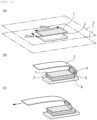
- That is, as illustrated in
FIG. 1A , the partial region of both surfaces of the electrode-separator composite are fixed (a: fixed portion) with the measuring rolls. After rotating the measuring rolls, the measuring rolls is spaced apart in the vertical direction with respect to the moving direction by applying the force to the electrode-separator composite, thereby separating the electrode-separator composite. - In the method for evaluating the adhesive strength of the separator according to the exemplary embodiment of the present application, the electrode-separator composite may be separated by rotating two measuring rolls and spacing the two measuring rolls apart from each other. The adhesive strength of the separator may be evaluated from a result of measuring the torque generated by the measuring rolls when the electrode-separator composite is separated. Therefore, it is possible that the adhesive strength of a plurality of separators is evaluated and the time in the process is reduced. In addition, it is possible to often and easily perform the evaluation, thereby efficiently controlling the process.
- In the exemplary embodiment of the present disclosure, the electrode may be a positive or negative electrode, preferably a negative electrode.
- In the exemplary embodiment of the present disclosure, the separator may be a safety reinforced separator (SRS) including a non-aqueous binder on a surface thereof.
- In the exemplary embodiment of the present disclosure, the electrode is a negative electrode, and the separator may be the safety reinforced separator.
- The safety reinforced separator may be the separator to which a method of coating ceramic particles and a polymer binder on the separator surface is applied, and may be the separator with reinforced durability and heat resistant. The polymer binder may be the non-aqueous binder.
- The positive electrode may be manufactured using a positive electrode active material including metal oxide primary particle, in this case, a concave-convex structure may be formed on the positive electrode surface by the metal oxide primary particle. In this case, the non-aqueous binder of the safety reinforced separator surface may be physically coupled with the concave-convex structure formed on the positive electrode surface to implement high adhesive strength of the positive electrode-separator.
- In contrast, since the negative electrode is manufactured using a negative electrode active material including carbon, it is relatively difficult to form the concave-convex structure on the negative electrode surface, therefore the adhesive strength of the positive electrode-separator is generally higher than the adhesive strength of the negative electrode-separator.
- Therefore, it is relatively more important to evaluate the adhesive strength of the negative electrode.
- In the exemplary embodiment of the present disclosure, the electrode may be in a shape of an electrode sheet.
- That is, the positive electrode may be a positive electrode sheet, and the negative electrode may be a negative electrode sheet. The electrode sheet may have a shape of an electrode plate of a specific or predetermined size by the cutting of the electrode-separator composite.
- In the exemplary embodiment of the present disclosure, the positive electrode and the positive electrode sheet may be manufactured by a method for manufacturing the positive electrode sheet using the positive electrode active material which is well known in the art, for example, by a method in which the positive electrode sheet is mixed with a binder or the like to manufacture a positive electrode slurry and the manufactured positive electrode slurry is applied, rolled, and dried on a positive electrode current collector.
- In this case, the positive electrode active material is not particularly limited if it is generally used for the positive electrode of the secondary battery in the art, but for example, lithium metal oxide (LiMO2) in a layered structure such as lithium cobaltate (LiCoO2) and a triatomic system, spinel material (LiM2O4) represented by lithium manganese oxide (LiM2O4), or olivine-based material (LiMPO4) such as lithium iron phosphate (LiFePO4) may be used. In addition, aluminum may be used as the positive electrode current collector.
- In the exemplary embodiment of the present disclosure, the negative electrode and the negative electrode sheet may be manufactured by a method for manufacturing the negative electrode sheet using the negative electrode active material which is well known in the art, for example, by a method in which the negative electrode sheet is mixed with a binder or the like to manufacture a negative electrode slurry and the manufactured positive electrode slurry is subsequently applied, rolled, and dried on a negative electrode current collector.
- In this case, the negative electrode active material is not particularly limited if it is generally used for the negative electrode of the secondary battery in the art, but for example, a carbon (C) based material, Si, Sn, tin oxide, composite tin alloys, transition metal oxide or lithium metal oxide, and the like may be used. In addition, copper or nickel may be used as the negative electrode current collector.
- In the exemplary embodiment of the present disclosure, the binder is for improving the adhering force between the positive or negative active materials, and those well known in the art may be used without limitation, for example, polyvinylidene fluoride (PVDF), polytetrafluoroethylene (PTFE), cellulose, polyvinyl alcohol, carboxymethylcellulose (CMC), starch, hydroxypropyl cellulose, regenerated cellulose, polyvinylpyrrolidone, tetrafluoroethylene, polyethylene, polypropylene, EPDM rubber, sulfonated EPDM or styrene butadiene rubber (SBR) and the like may be used, but not limited thereto.
- In the exemplary embodiment of the present disclosure, the positive electrode slurry or negative electrode slurry may further include a conductive material or a filler. Materials commonly used in the art may be used as the conductive material and the filler.
- Specifically, carbon black such as Denka black, acetylene black, Ketjen black, furnace black, thermal black, etc., one or more types selected from a group consisting of natural graphite and artificial graphite may be used as the conductive material, but the conductive material is not limited thereto, and the conductive material which has conductivity without causing chemical changes in the constituted battery may be generally used.
- In addition, one or more types selected from a group consisting of polyethylene, polypropylene, glass fiber, and carbon fiber may be used as the filler, but is not limited thereto, and a fibrous material which does not cause chemical changes in the constituted battery may be generally used as the filler.
- In the exemplary embodiment of the present disclosure, a thickness of the positive electrode is 50 µm to 300 µm, preferably 100 µm to 200 µm,but not limited thereto.
- In the exemplary embodiment of the present disclosure, a thickness of the negative electrode is 50 µm to 300 µm, preferably 100 µm to 200 µm,but not limited thereto.
- Since a capacity of the negative electrode should be greater than that of the positive electrode, the thickness of the negative electrode is thicker than that of the positive electrode.
- In the present specification, the thickness of the electrode may be measured by scanning a cross-section of the electrode using a Scanning Electron Microscope (SEM). In this case, the thickness of the electrode means the thickness including both the electrode current collector and the electrode active material layer.
- In the exemplary embodiment of the present disclosure, the separator may be in a shape of a separator sheet. The separator sheet may have a separator shape of a specific or predetermined size by the cutting of the electrode-separator composite.
- In the exemplary embodiment of the present disclosure, an olefin-based polymer, a sheet, a non-woven fabric, and kraft paper made of glass fiber, polyethylene, or the like may be used as the separator, and the olefin-based polymer may be preferably used.
- More specifically, one or more types selected from a group consisting of high density polyethylene, low density polyethylene, linear low density polyethylene, ultra-high molecular weight polyethylene, polypropylene, polyethyleneterephthalate, polybutyleneterephthalate, polyester, polyacetal, polyamide, polycarbonate, polyimide, polyetheretherketone, polyethersulfone, polyphenyleneoxide, polyphenylenesulfidro, polyethylenenaphthalene and mixtures thereof may be used as the separator, but not limited thereto.
- In the exemplary embodiment of the present disclosure, a thickness of the separator is 3 µm to 50 µm,preferably 10 µm to 30 µm,but not limited thereto.
- In the present specification, the thickness of the separator may be measured by scanning a cross-section of the separator using SEM.
- In the exemplary embodiment of the present disclosure, the cutting of the electrode-separator composite may be performed using a knife, a mold, scissors or a laser, but not limited thereto.
- In the exemplary embodiment of the present disclosure, the cutting of the electrode-separator composite may be performed by a cutting roll.
- In this regard,
FIG. 4 is a top plan view illustrating a cutting process of the method for evaluating the adhesive strength of the separator according to the present disclosure. While theseparator 1 and theelectrode 2 are supplied between the cutting rolls 12 and 13, the electrode is stacked on at least one surface of the separator, heated and pressurized, and subsequently the electrode-separator composite in which the adhesive and non-adhesive surfaces of the separator and electrode are alternately disposed passes through the cutting rolls, the electrode-separator composite may be cut in a direction parallel to the moving direction (the adhesive and non-adhesive surfaces and some configurations are not illustrated). - In the exemplary embodiment of the present disclosure, a distance between the cut portions in the cutting of the electrode-separator composite in the direction parallel to the moving direction may be equal.
- In the exemplary embodiment of the present disclosure, a distance between portions which is cut in the cutting of the electrode-separator composite in the direction parallel to the moving direction may be different.
- In the present specification, the 'cutting roll' is a device for cutting the electrode-separator composite.
- In the exemplary embodiment of the present disclosure, the moving of the electrode-separator composite may be performed by a conveyor belt, but not limited thereto, all means for moving the electrode-separator composite in a predetermined direction may be used.
- In the present specification, the direction in which the electrode-separator composite is moved may be referred to as a 'manufacturing direction'. That is, the cutting of the electrode-separator composite in the direction parallel to the moving direction means that the cutting of the electrode-separator composite cuts the electrode-separator composite at a predetermined interval parallel to the manufacturing direction (MD). As described above, it is possible to improve an accuracy of evaluating the adhesive strength by cutting the electrode-separator composite at a predetermined interval, and also to reduce the evaluating time of the adhesive strength by obtaining a plurality of electrode-separator composites capable of evaluating the adhesive strength.
- In the exemplary embodiment of the present disclosure, the cutting of the electrode-separator composite in the direction parallel to the moving direction may be cutting the electrode-separator composite at a predetermined interval.
- In the present specification, 'cutting the electrode-separator composite at a predetermined interval' means that a distance between one cutting surface of one electrode-separator composite which is cut parallel to the manufacturing direction (MD) and the opposite cutting surface thereof has a predetermined size (or length). In addition, the predetermined size (or length) means that a deviation of size (or length) is ±1 mm.
- In the present specification, "the attaching of the measuring rolls to each of the two surfaces of the cut electrode-separator composite" means that the measuring rolls are in contact with each of both surfaces of the electrode-separator composite so that a predetermined force may be applied to both surfaces of the cut electrode-separator composite.
- In this regard,
FIG. 5 is a top plan view of a measurement process of the method for evaluating the adhesive strength of the separator according to the present disclosure. The measuring rolls 14 and 15 are attached to the electrode-separator composite which is cut in the direction parallel to the moving direction by the cutting rolls 12 and 13, and the evaluation of the adhesive strength of the separator is performed as described below (adhesive and non-adhesive surfaces and some configurations are not illustrated). - In the exemplary embodiment of the present disclosure, the measuring of the torque generated by the measuring rolls while separating the electrode-separator composite may use a torque sensor.
- In the exemplary embodiment of the present disclosure, the measuring of the torque generated by the measuring rolls while separating the electrode-separator composite may include: measuring a torque generated by the measuring rolls when the non-adhesive surfaces in the electrode-separator composite are separated by the measuring rolls; determining the torque measured when the non-adhesive surfaces are separated by the measuring rolls as a reference for zero-point adjustment; and measuring a torque generated by the measuring rolls when the adhesive surfaces in the electrode-separator composite are separated by the measuring rolls. That is, the torque measured when portions (non-adhesive surfaces) in which the adhesive strength is not made in the electrode-composite are separated (or opened) is set to zero-point, and thereafter, the torque when portions in which the adhesive strength is made (adhesive surfaces) are separated (or opened) may be measured. The adhesive strength of the electrode-separator composite may be expressed as a specific value from the measured torque value, thereby evaluating the adhesive strength.
- In the present specification, the meaning of "electrode-separator composite is separated" more specifically means that the electrode and separator of the electrode-separator composite are separated and opened as illustrated in
FIG. 1A . - In the method for evaluating the adhesive strength of the separator according to the exemplary embodiment of the present disclosure obtaining the adhesive strength from the measured torque is defined by calculating the adhesive strength by
equation 1 below.
- In the
equation 1 above, - S is an adhesive strength of a separator (unit: kgf; 1kgf=9.81N),
- F is a magnitude (unit: kgf·m) of a torque generated by measuring rolls while separating an electrode-separator composite (unit: kgf·m),
- d is the shortest distance between an electrode and a rotating axis of a measuring roll (unit: m)
- A is an angle (unit: rad) formed by an electrode-separator composite and an electrode after separation.
- In the present specification, "a magnitude of the torque generated by the measuring rolls while separating the electrode-separator composite" means a value measuring a torque generated by the measuring rolls using a torque sensor or the like. That is, it means a torque measured by the measuring rolls.
- In the present specification, sin means trigonometric function, and sin A means the sin value of angle A (unit: radian).
- The method for evaluating the adhesive strength of the separator according to the exemplary embodiment of the present disclosure may be to evaluate the adhesive strength of the electrode-separator composite from a difference between the adhesive strength calculated by
Equation 1 when the non-adhesive surfaces in the electrode-separator composite are separated by the measuring rolls and the adhesive strength calculated byEquation 1 when the adhesive surfaces in the electrode-separator composite are separated by the measuring rolls. - The method for evaluating the adhesive strength of the separator according to the exemplary embodiment of the present disclosure may be performed by a roll-to-roll process. Therefore, the evaluation of the adhesive strength may be performed at one time by a continuous process.
- Specifically, as illustrated in
FIG. 1B , the method for evaluating the adhesive strength of the separator of the present disclosure is performed as described below. First, a lamination process is performed, in which theseparator 1 and theelectrode 2 are supplied between two lamination rolls 10 and 11 with a predetermined pattern formed and the electrode is stacked on at least one surface of the separator and heated and pressurized to form the electrode-separator composite in which the adhesive and non-adhesive surfaces of the separator and electrode are alternatively disposed. In the lamination process, the process of stacking, heating and pressurizing may be performed together. That is, the electrode-separator composite is manufactured by the pattern lamination. Subsequently, the manufactured electrode-separator composite is supplied between the cutting rolls 12 and 13 and a cutting process is performed to cut the electrode-separator composite at a predetermined interval on the basis of the manufacturing direction (MD). Thereafter, the measuring rolls 14 and 15 are attached to both surfaces of the electrode-separator composite which is cut at the predetermined interval, and the electrode and separator are fixed to the measuring rolls, respectively, while each measuring roll rotates. Subsequently, while rotating and spacing the measuring rolls apart from each other, a force is applied to both surfaces of the electrode-separator composite, that is, to the separator and the electrode, respectively. Therefore, as the separation of the electrode-separator composite is performed, the electrode and the separator are detached, and the electrode-separator composite is opened. - In this case, the torque measured when the portions (non-adhesive surfaces) in which the adhesive strength is not made are separated (or opened) is set to zero-point, and thereafter, the torque when the portions in which the adhesive strength is made (adhesive surfaces) are separated (or opened) may be measured, thereby, evaluating the adhesive strength of the electrode-separator composite. More specifically, the adhesive strength is evaluated from the value of the difference between the adhesive strength calculated by
Equation 1 when the non-adhesive surfaces in the electrode-separator composite are separated by the measuring rolls and the adhesive strength calculated byEquation 1 when the adhesive surfaces in the electrode-separator composite are separated by the measuring rolls. In this case, the process from the deformation by the measuring rolls 14 and 15 to the evaluation of the adhesive strength is defined as a measurement process. - In this case, the cutting rolls 12, 13, and measuring rolls may be applied in one or more pairs. For an example of
FIG. 1B , the electrode-separator composite may be divided into three pieces by cutting the electrode-separator composite to have a predetermined interval by a pair of cutting rolls 12 and 13, and the measuring rolls 14 and 15 may be attached to each of the electrode-separator composites, thereby applying the evaluation of the adhesive strength. That is, three pairs of measuring rolls 14-1, 15-1, 14-2, 15-2, 14-3, and 15-3 may be used. - In addition, in
FIG. 1 , ZD corresponds to a thickness direction of material in a facility, MD means a direction parallel to the moving direction of material in the facility, that is, the manufacturing direction, and CD means a direction parallel to a width direction of material in the facility and perpendicular to the MD. - These processes may be performed at one time by the roll-to-roll process as described above.
- According to the method for evaluating the adhesive strength of the separator of the exemplary embodiment of the present disclosure, as illustrated in
FIG. 6 , theelectrode 2 is stacked on at least one surface of theseparator 1, and surfaces of the separator and the electrode facing each other include the adhesive surfaces and non-adhesive surfaces of the separator and electrode, and when the electrode-separator composite in which the adhesive and non-adhesive surfaces of theseparator 1 andelectrode 2 are alternately disposed is separated by the measuring rolls 14 and 15, the torque sensed in the measuringroll 15 to which the electrode is attached by the torque sensor (not illustrated) is recorded in real time. In addition, the angle A formed by the electrode-separator composite and the electrode after separation is also recorded by a computer vision system (not illustrated). - The value measured from the record may be substituted into
Equation 1 to obtain the adhesive strength of the separator in real time. That is, it is possible to continuously perform the evaluation of the adhesive strength of the separator at various positions of the electrode-separator composite. Therefore, according to the exemplary embodiment of the method for evaluating the adhesive strength of the separator of the present application, it is possible to obtain an advantageous effect of reducing the time required for the evaluation, reducing the possibility of defects occurring in the process, and also efficiently controlling the process.
Claims (9)
- A method for evaluating an adhesive strength of a separator (1), the method comprising:manufacturing an electrode-separator composite in which an electrode (2) is stacked on at least one surface of a separator (1), and surfaces of the separator (1) and the electrode (2) facing each other include adhesive surfaces and non-adhesive surfaces of the separator (1) and the electrode (2), and the adhesive surfaces and the non-adhesive surfaces are alternately disposed;moving the electrode-separator composite;cutting the electrode-separator composite in a direction parallel to the moving direction;attaching measuring rolls (14, 15) respectively to both surfaces of the cut electrode-separator composite;separating the electrode-separator composite by rotating each of the attached measuring rolls (14, 15) and spacing the measuring rolls (14, 15) apart from each other; andmeasuring a torque generated by the measuring rolls (14, 15) while separating the electrode-separator composite, andobtaining an adhesive strength from the measured torque.
- The method of claim 1, wherein the manufacturing of the electrode-separator composite in which the electrode (2) is stacked on at least one surface of the separator (1), and surfaces of the separator (1) and the electrode (2) facing each other include the adhesive surfaces and the non-adhesive surfaces of the separator (1) and the electrode (2), and the adhesive surfaces and the non-adhesive surfaces are alternately disposed, comprises:manufacturing a laminate by stacking the electrode (2) on at least one surface of the separator (1); andheating and pressurizing only a partial region of the laminate, wherein the partial region corresponds to the adhesive surfaces of the electrode-separator composite.
- The method of claim 2, wherein the manufacturing of the laminate by stacking the electrode (2) on at least one surface of the separator (1) and the heating and pressurizing of only the partial region of the laminate are performed simultaneously using lamination rolls (10, 11) including a spaced pattern.
- The method of claim 2, wherein the heating and pressurizing of only the partial region of the laminate heats and pressurizes the partial region at a temperature of 60°C to 120°C and a pressure of 980.7 kPa (10 kgf/cm2) to 9807 kPa (100 kgf/cm2).
- The method of claim 1, wherein the adhesive surface forms a stripe shape in a direction parallel to a rotating axis of the measuring roll (14, 15).
- The method of claim 1, wherein the measuring of the torque generated by the measuring roll (14, 15) while separating the electrode-separator composite uses a torque sensor.
- The method of claim 1, wherein the measuring of the torque generated by the measuring rolls (14, 15) while separating the electrode-separator composite comprises:measuring a torque generated by the measuring rolls (14, 15) when the non-adhesive surfaces in the electrode-separator composite are separated by the measuring rolls (14, 15);determining the torque measured when the non-adhesive surfaces are separated by the measuring roll (14, 15) as a reference for zero-point adjustment; andmeasuring a torque generated by the measuring rolls (14, 15) when the adhesive surfaces in the electrode-separator composite are separated by the measuring rolls (14, 15).
- The method of claim 1,wherein obtaining an adhesive strength from the measured torque is defined by calculating the adhesive strength by Equation 1 below:
 in Equation 1, S is an adhesive strength of a separator (1) (unit: kgf; 1kgf=9.81 N), F is a magnitude (unit: kgf·m) of a torque generated by the measuring rolls (14, 15)while separating an electrode-separator composite, d is a shortest distance between an electrode (2) and a rotating axis of a measuring roll (14, 15) (unit: m), and A is an angle (unit: rad) formed by an electrode-separator composite and an electrode (2)after separation.
 - The method of claim 8, wherein the obtaining of the adhesive strength from the measured torque is evaluating the adhesive strength of the electrode-separator composite from a difference between the adhesive strength calculated by Equation 1 when the non-adhesive surfaces in the electrode-separator composite are separated by the measuring rolls (14, 15) and the adhesive strength calculated by Equation 1 when the adhesive surfaces in the electrode-separator composite are separated by the measuring rolls (14, 15).
Applications Claiming Priority (2)
| Application Number | Priority Date | Filing Date | Title |
|---|---|---|---|
| KR1020210160462A KR20230073753A (en) | 2021-11-19 | 2021-11-19 | Separator adhesion evaluation method |
| PCT/KR2022/016936 WO2023090693A1 (en) | 2021-11-19 | 2022-11-01 | Method for evaluating adhesion of separator |
Publications (3)
| Publication Number | Publication Date |
|---|---|
| EP4286830A1 EP4286830A1 (en) | 2023-12-06 |
| EP4286830A4 EP4286830A4 (en) | 2024-09-18 |
| EP4286830B1 true EP4286830B1 (en) | 2025-06-25 |
Family
ID=86397371
Family Applications (1)
| Application Number | Title | Priority Date | Filing Date |
|---|---|---|---|
| EP22895900.3A Active EP4286830B1 (en) | 2021-11-19 | 2022-11-01 | Method for evaluating adhesion of separator |
Country Status (8)
| Country | Link |
|---|---|
| US (1) | US20240159653A1 (en) |
| EP (1) | EP4286830B1 (en) |
| JP (1) | JP7655633B2 (en) |
| KR (1) | KR20230073753A (en) |
| CN (1) | CN117063058A (en) |
| ES (1) | ES3041947T3 (en) |
| HU (1) | HUE072943T2 (en) |
| WO (1) | WO2023090693A1 (en) |
Families Citing this family (2)
| Publication number | Priority date | Publication date | Assignee | Title |
|---|---|---|---|---|
| CN118425028B (en) * | 2024-07-03 | 2024-10-22 | 深圳铱创科技有限公司 | On-line detection device and detection method for coating quality of anode surface |
| CN118518581B (en) * | 2024-07-23 | 2024-09-27 | 湖南新美佳鞋业股份有限公司 | Adhesive bonding tension detection device |
Family Cites Families (15)
| Publication number | Priority date | Publication date | Assignee | Title |
|---|---|---|---|---|
| JPH0715438B2 (en) * | 1986-09-27 | 1995-02-22 | 新王子製紙株式会社 | Adhesive strength measuring method and measuring instrument |
| JP2733133B2 (en) * | 1990-11-13 | 1998-03-30 | 川崎製鉄株式会社 | Continuous measuring device for T-peel strength of laminate |
| JPH07104266B2 (en) * | 1991-04-26 | 1995-11-13 | 日本製紙株式会社 | Method for measuring internal bond strength of sheet-like material and measuring apparatus therefor |
| JP2002005817A (en) * | 2000-06-16 | 2002-01-09 | Mitsubishi Heavy Ind Ltd | Coating film adhesion evaluating method and device therefor and electrode plate manufacturing method |
| CA2373344C (en) * | 2001-02-28 | 2012-03-20 | Daido Tokushuko Kabushiki Kaisha | Corrosion-resistant metallic member, metallic separator for fuel cell comprising the same, and process for production thereof |
| JP2009210463A (en) * | 2008-03-05 | 2009-09-17 | Bridgestone Corp | Tackiness measuring instrument |
| JP2013062139A (en) * | 2011-09-13 | 2013-04-04 | Toyota Motor Corp | Evaluation method of electrode |
| KR101664945B1 (en) | 2014-08-21 | 2016-10-11 | 주식회사 엘지화학 | Method for manufacturing electrode assembly and electrode assembly manufactured using the same |
| FR3028313B1 (en) * | 2014-11-06 | 2021-01-01 | Snecma | DEVICE AND METHOD FOR PELING TESTS |
| CN104596923B (en) * | 2014-12-31 | 2017-02-01 | 山东华夏神舟新材料有限公司 | Measuring method for adhesive strength of flexible substrate material coating |
| KR102111105B1 (en) * | 2016-10-10 | 2020-05-14 | 주식회사 엘지화학 | Unit cell for the secondary battery having improved wettability and Method for manufacturing the same |
| CN106769845A (en) * | 2016-12-27 | 2017-05-31 | 深圳市星源材质科技股份有限公司 | The characterizing method of cohesive force between a kind of polymer-coated lithium battery diaphragm and pole piece |
| KR102315719B1 (en) * | 2017-04-12 | 2021-10-21 | 주식회사 엘지에너지솔루션 | Electrode Assembly Having Non-Uniform Adhesive Strength of Electrode Mixture Layer and Apparatus for Manufacturing the Same |
| KR102606425B1 (en) * | 2018-09-05 | 2023-11-27 | 주식회사 엘지에너지솔루션 | Method for performance analysis of secondary battery electrode |
| JP7338523B2 (en) * | 2020-03-17 | 2023-09-05 | 株式会社村田製作所 | Tape peel strength measuring device |
-
2021
- 2021-11-19 KR KR1020210160462A patent/KR20230073753A/en active Pending
-
2022
- 2022-11-01 WO PCT/KR2022/016936 patent/WO2023090693A1/en not_active Ceased
- 2022-11-01 JP JP2023556839A patent/JP7655633B2/en active Active
- 2022-11-01 US US18/282,952 patent/US20240159653A1/en active Pending
- 2022-11-01 CN CN202280024968.0A patent/CN117063058A/en active Pending
- 2022-11-01 HU HUE22895900A patent/HUE072943T2/en unknown
- 2022-11-01 ES ES22895900T patent/ES3041947T3/en active Active
- 2022-11-01 EP EP22895900.3A patent/EP4286830B1/en active Active
Also Published As
| Publication number | Publication date |
|---|---|
| CN117063058A (en) | 2023-11-14 |
| EP4286830A1 (en) | 2023-12-06 |
| US20240159653A1 (en) | 2024-05-16 |
| WO2023090693A1 (en) | 2023-05-25 |
| KR20230073753A (en) | 2023-05-26 |
| JP2024511344A (en) | 2024-03-13 |
| HUE072943T2 (en) | 2025-12-28 |
| JP7655633B2 (en) | 2025-04-02 |
| ES3041947T3 (en) | 2025-11-17 |
| EP4286830A4 (en) | 2024-09-18 |
Similar Documents
| Publication | Publication Date | Title |
|---|---|---|
| KR102303703B1 (en) | Solid-state battery and method for manufacturing the same | |
| JP5747506B2 (en) | Method for manufacturing electrode laminate and electrode laminate | |
| KR101664945B1 (en) | Method for manufacturing electrode assembly and electrode assembly manufactured using the same | |
| EP4286830B1 (en) | Method for evaluating adhesion of separator | |
| CN108933266B (en) | Battery and method for manufacturing same | |
| US20120237825A1 (en) | Method for producing battery electrode | |
| CN114730907A (en) | Inspection method and method for manufacturing assembled battery | |
| CN103959542A (en) | Electrode assembly, manufacturing method of the electrode assembly, and electrochemical cell comprising the electrode assembly | |
| JP2016072026A (en) | Machine for manufacturing power storage device and method for manufacturing power storage device | |
| KR20220118250A (en) | Device and method for detecting damage to monocell type separator | |
| KR102913788B1 (en) | Method of inspecting welding defects | |
| JP7442655B2 (en) | Electrode rolling equipment and electrode rolling method | |
| EP4156360B1 (en) | Mono-cell manufacturing device having glossmeter and manufacturing method using same | |
| US20230098222A1 (en) | Evaluation method and evaluation system for separator for battery, production method for separator for battery, production method for electrode unit, and production method for battery | |
| KR102940139B1 (en) | Method of evaluating the degree of secession of electrode active material | |
| WO2022244759A1 (en) | Inspection method for layered sheet, production method for layered sheet, and production method for battery pack | |
| KR20230040511A (en) | Estimation method of adhesive force between separator and electrode | |
| US20230134414A1 (en) | Laminator for Manufacture of Unit Structural Bodies with Increased Force of Adhesion | |
| JP2022176624A (en) | Method for inspecting laminated sheet, method for manufacturing laminated sheet, and method for manufacturing battery pack | |
| JP2012132855A (en) | Inspection method and inspection device of electrode sheet for battery | |
| EP4465395A1 (en) | Non-aqueous electrolyte secondary battery | |
| EP4668386A1 (en) | Compressing device, capable of real-time monitoring of compressing force, for formation of secondary battery, and compressing method thereof | |
| KR20220136086A (en) | Mono Cell Manufacturing Device Equipped With Gloss Meter And Manufacturing Method Using It | |
| JP2025162687A (en) | Battery charge/discharge inspection method | |
| JP2022176623A (en) | Method for inspecting laminated sheet, method for manufacturing laminated sheet, and method for manufacturing battery pack |
Legal Events
| Date | Code | Title | Description |
|---|---|---|---|
| STAA | Information on the status of an ep patent application or granted ep patent |
Free format text: STATUS: THE INTERNATIONAL PUBLICATION HAS BEEN MADE |
|
| PUAI | Public reference made under article 153(3) epc to a published international application that has entered the european phase |
Free format text: ORIGINAL CODE: 0009012 |
|
| STAA | Information on the status of an ep patent application or granted ep patent |
Free format text: STATUS: REQUEST FOR EXAMINATION WAS MADE |
|
| 17P | Request for examination filed |
Effective date: 20230901 |
|
| AK | Designated contracting states |
Kind code of ref document: A1 Designated state(s): AL AT BE BG CH CY CZ DE DK EE ES FI FR GB GR HR HU IE IS IT LI LT LU LV MC ME MK MT NL NO PL PT RO RS SE SI SK SM TR |
|
| A4 | Supplementary search report drawn up and despatched |
Effective date: 20240819 |
|
| RIC1 | Information provided on ipc code assigned before grant |
Ipc: H01M 50/46 20210101ALI20240812BHEP Ipc: G01L 3/00 20060101ALI20240812BHEP Ipc: G01N 19/04 20060101AFI20240812BHEP |
|
| DAV | Request for validation of the european patent (deleted) | ||
| DAX | Request for extension of the european patent (deleted) | ||
| GRAP | Despatch of communication of intention to grant a patent |
Free format text: ORIGINAL CODE: EPIDOSNIGR1 |
|
| STAA | Information on the status of an ep patent application or granted ep patent |
Free format text: STATUS: GRANT OF PATENT IS INTENDED |
|
| INTG | Intention to grant announced |
Effective date: 20250324 |
|
| GRAS | Grant fee paid |
Free format text: ORIGINAL CODE: EPIDOSNIGR3 |
|
| GRAA | (expected) grant |
Free format text: ORIGINAL CODE: 0009210 |
|
| STAA | Information on the status of an ep patent application or granted ep patent |
Free format text: STATUS: THE PATENT HAS BEEN GRANTED |
|
| P01 | Opt-out of the competence of the unified patent court (upc) registered |
Free format text: CASE NUMBER: APP_21195/2025 Effective date: 20250505 |
|
| AK | Designated contracting states |
Kind code of ref document: B1 Designated state(s): AL AT BE BG CH CY CZ DE DK EE ES FI FR GB GR HR HU IE IS IT LI LT LU LV MC ME MK MT NL NO PL PT RO RS SE SI SK SM TR |
|
| REG | Reference to a national code |
Ref country code: GB Ref legal event code: FG4D |
|
| REG | Reference to a national code |
Ref country code: CH Ref legal event code: EP |
|
| REG | Reference to a national code |
Ref country code: CH Ref legal event code: EP |
|
| REG | Reference to a national code |
Ref country code: IE Ref legal event code: FG4D |
|
| REG | Reference to a national code |
Ref country code: DE Ref legal event code: R096 Ref document number: 602022016630 Country of ref document: DE |
|
| PG25 | Lapsed in a contracting state [announced via postgrant information from national office to epo] |
Ref country code: FI Free format text: LAPSE BECAUSE OF FAILURE TO SUBMIT A TRANSLATION OF THE DESCRIPTION OR TO PAY THE FEE WITHIN THE PRESCRIBED TIME-LIMIT Effective date: 20250625 |
|
| REG | Reference to a national code |
Ref country code: LT Ref legal event code: MG9D |
|
| PG25 | Lapsed in a contracting state [announced via postgrant information from national office to epo] |
Ref country code: GR Free format text: LAPSE BECAUSE OF FAILURE TO SUBMIT A TRANSLATION OF THE DESCRIPTION OR TO PAY THE FEE WITHIN THE PRESCRIBED TIME-LIMIT Effective date: 20250926 Ref country code: NO Free format text: LAPSE BECAUSE OF FAILURE TO SUBMIT A TRANSLATION OF THE DESCRIPTION OR TO PAY THE FEE WITHIN THE PRESCRIBED TIME-LIMIT Effective date: 20250925 |
|
| PG25 | Lapsed in a contracting state [announced via postgrant information from national office to epo] |
Ref country code: BG Free format text: LAPSE BECAUSE OF FAILURE TO SUBMIT A TRANSLATION OF THE DESCRIPTION OR TO PAY THE FEE WITHIN THE PRESCRIBED TIME-LIMIT Effective date: 20250625 |
|
| PG25 | Lapsed in a contracting state [announced via postgrant information from national office to epo] |
Ref country code: HR Free format text: LAPSE BECAUSE OF FAILURE TO SUBMIT A TRANSLATION OF THE DESCRIPTION OR TO PAY THE FEE WITHIN THE PRESCRIBED TIME-LIMIT Effective date: 20250625 |
|
| PG25 | Lapsed in a contracting state [announced via postgrant information from national office to epo] |
Ref country code: RS Free format text: LAPSE BECAUSE OF FAILURE TO SUBMIT A TRANSLATION OF THE DESCRIPTION OR TO PAY THE FEE WITHIN THE PRESCRIBED TIME-LIMIT Effective date: 20250925 |
|
| PG25 | Lapsed in a contracting state [announced via postgrant information from national office to epo] |
Ref country code: LV Free format text: LAPSE BECAUSE OF FAILURE TO SUBMIT A TRANSLATION OF THE DESCRIPTION OR TO PAY THE FEE WITHIN THE PRESCRIBED TIME-LIMIT Effective date: 20250625 |
|
| REG | Reference to a national code |
Ref country code: NL Ref legal event code: MP Effective date: 20250625 |
|
| PG25 | Lapsed in a contracting state [announced via postgrant information from national office to epo] |
Ref country code: NL Free format text: LAPSE BECAUSE OF FAILURE TO SUBMIT A TRANSLATION OF THE DESCRIPTION OR TO PAY THE FEE WITHIN THE PRESCRIBED TIME-LIMIT Effective date: 20250625 |
|
| REG | Reference to a national code |
Ref country code: ES Ref legal event code: FG2A Ref document number: 3041947 Country of ref document: ES Kind code of ref document: T3 Effective date: 20251117 |
|
| PG25 | Lapsed in a contracting state [announced via postgrant information from national office to epo] |
Ref country code: PT Free format text: LAPSE BECAUSE OF FAILURE TO SUBMIT A TRANSLATION OF THE DESCRIPTION OR TO PAY THE FEE WITHIN THE PRESCRIBED TIME-LIMIT Effective date: 20251027 |
|
| PGFP | Annual fee paid to national office [announced via postgrant information from national office to epo] |
Ref country code: HU Payment date: 20251127 Year of fee payment: 4 |
|
| REG | Reference to a national code |
Ref country code: AT Ref legal event code: MK05 Ref document number: 1806904 Country of ref document: AT Kind code of ref document: T Effective date: 20250625 |
|
| REG | Reference to a national code |
Ref country code: HU Ref legal event code: AG4A Ref document number: E072943 Country of ref document: HU |
|
| PG25 | Lapsed in a contracting state [announced via postgrant information from national office to epo] |
Ref country code: IS Free format text: LAPSE BECAUSE OF FAILURE TO SUBMIT A TRANSLATION OF THE DESCRIPTION OR TO PAY THE FEE WITHIN THE PRESCRIBED TIME-LIMIT Effective date: 20251025 |
|
| PGFP | Annual fee paid to national office [announced via postgrant information from national office to epo] |
Ref country code: DE Payment date: 20251020 Year of fee payment: 4 |
|
| PG25 | Lapsed in a contracting state [announced via postgrant information from national office to epo] |
Ref country code: AT Free format text: LAPSE BECAUSE OF FAILURE TO SUBMIT A TRANSLATION OF THE DESCRIPTION OR TO PAY THE FEE WITHIN THE PRESCRIBED TIME-LIMIT Effective date: 20250625 Ref country code: SM Free format text: LAPSE BECAUSE OF FAILURE TO SUBMIT A TRANSLATION OF THE DESCRIPTION OR TO PAY THE FEE WITHIN THE PRESCRIBED TIME-LIMIT Effective date: 20250625 |
|
| PGFP | Annual fee paid to national office [announced via postgrant information from national office to epo] |
Ref country code: FR Payment date: 20251021 Year of fee payment: 4 |
|
| PGFP | Annual fee paid to national office [announced via postgrant information from national office to epo] |
Ref country code: BE Payment date: 20251020 Year of fee payment: 4 |
|
| PG25 | Lapsed in a contracting state [announced via postgrant information from national office to epo] |
Ref country code: CZ Free format text: LAPSE BECAUSE OF FAILURE TO SUBMIT A TRANSLATION OF THE DESCRIPTION OR TO PAY THE FEE WITHIN THE PRESCRIBED TIME-LIMIT Effective date: 20250625 |
|
| PG25 | Lapsed in a contracting state [announced via postgrant information from national office to epo] |
Ref country code: PL Free format text: LAPSE BECAUSE OF FAILURE TO SUBMIT A TRANSLATION OF THE DESCRIPTION OR TO PAY THE FEE WITHIN THE PRESCRIBED TIME-LIMIT Effective date: 20250625 |
|
| PG25 | Lapsed in a contracting state [announced via postgrant information from national office to epo] |
Ref country code: EE Free format text: LAPSE BECAUSE OF FAILURE TO SUBMIT A TRANSLATION OF THE DESCRIPTION OR TO PAY THE FEE WITHIN THE PRESCRIBED TIME-LIMIT Effective date: 20250625 |
|
| PG25 | Lapsed in a contracting state [announced via postgrant information from national office to epo] |
Ref country code: SK Free format text: LAPSE BECAUSE OF FAILURE TO SUBMIT A TRANSLATION OF THE DESCRIPTION OR TO PAY THE FEE WITHIN THE PRESCRIBED TIME-LIMIT Effective date: 20250625 |
|
| PGFP | Annual fee paid to national office [announced via postgrant information from national office to epo] |
Ref country code: ES Payment date: 20251215 Year of fee payment: 4 |
|
| PG25 | Lapsed in a contracting state [announced via postgrant information from national office to epo] |
Ref country code: RO Free format text: LAPSE BECAUSE OF FAILURE TO SUBMIT A TRANSLATION OF THE DESCRIPTION OR TO PAY THE FEE WITHIN THE PRESCRIBED TIME-LIMIT Effective date: 20250625 |
|
| PG25 | Lapsed in a contracting state [announced via postgrant information from national office to epo] |
Ref country code: DK Free format text: LAPSE BECAUSE OF FAILURE TO SUBMIT A TRANSLATION OF THE DESCRIPTION OR TO PAY THE FEE WITHIN THE PRESCRIBED TIME-LIMIT Effective date: 20250625 |
|
| PG25 | Lapsed in a contracting state [announced via postgrant information from national office to epo] |
Ref country code: IT Free format text: LAPSE BECAUSE OF FAILURE TO SUBMIT A TRANSLATION OF THE DESCRIPTION OR TO PAY THE FEE WITHIN THE PRESCRIBED TIME-LIMIT Effective date: 20250625 |