EP4131195B1 - Warnvorrichtung für gefährliches fahren, warnsystem für gefährliches fahren und warnverfahren für gefährliches fahren - Google Patents
Warnvorrichtung für gefährliches fahren, warnsystem für gefährliches fahren und warnverfahren für gefährliches fahren Download PDFInfo
- Publication number
- EP4131195B1 EP4131195B1 EP20927720.1A EP20927720A EP4131195B1 EP 4131195 B1 EP4131195 B1 EP 4131195B1 EP 20927720 A EP20927720 A EP 20927720A EP 4131195 B1 EP4131195 B1 EP 4131195B1
- Authority
- EP
- European Patent Office
- Prior art keywords
- vehicle
- host
- degree
- agitating
- driver
- Prior art date
- Legal status (The legal status is an assumption and is not a legal conclusion. Google has not performed a legal analysis and makes no representation as to the accuracy of the status listed.)
- Active
Links
Images








Classifications
-
- B—PERFORMING OPERATIONS; TRANSPORTING
- B60—VEHICLES IN GENERAL
- B60W—CONJOINT CONTROL OF VEHICLE SUB-UNITS OF DIFFERENT TYPE OR DIFFERENT FUNCTION; CONTROL SYSTEMS SPECIALLY ADAPTED FOR HYBRID VEHICLES; ROAD VEHICLE DRIVE CONTROL SYSTEMS FOR PURPOSES NOT RELATED TO THE CONTROL OF A PARTICULAR SUB-UNIT
- B60W40/00—Estimation or calculation of non-directly measurable driving parameters for road vehicle drive control systems not related to the control of a particular sub unit, e.g. by using mathematical models
- B60W40/08—Estimation or calculation of non-directly measurable driving parameters for road vehicle drive control systems not related to the control of a particular sub unit, e.g. by using mathematical models related to drivers or passengers
-
- G—PHYSICS
- G08—SIGNALLING
- G08B—SIGNALLING SYSTEMS, e.g. PERSONAL CALLING SYSTEMS; ORDER TELEGRAPHS; ALARM SYSTEMS
- G08B21/00—Alarms responsive to a single specified undesired or abnormal condition and not otherwise provided for
- G08B21/02—Alarms for ensuring the safety of persons
- G08B21/06—Alarms for ensuring the safety of persons indicating a condition of sleep, e.g. anti-dozing alarms
-
- B—PERFORMING OPERATIONS; TRANSPORTING
- B60—VEHICLES IN GENERAL
- B60W—CONJOINT CONTROL OF VEHICLE SUB-UNITS OF DIFFERENT TYPE OR DIFFERENT FUNCTION; CONTROL SYSTEMS SPECIALLY ADAPTED FOR HYBRID VEHICLES; ROAD VEHICLE DRIVE CONTROL SYSTEMS FOR PURPOSES NOT RELATED TO THE CONTROL OF A PARTICULAR SUB-UNIT
- B60W40/00—Estimation or calculation of non-directly measurable driving parameters for road vehicle drive control systems not related to the control of a particular sub unit, e.g. by using mathematical models
- B60W40/10—Estimation or calculation of non-directly measurable driving parameters for road vehicle drive control systems not related to the control of a particular sub unit, e.g. by using mathematical models related to vehicle motion
- B60W40/105—Speed
-
- B—PERFORMING OPERATIONS; TRANSPORTING
- B60—VEHICLES IN GENERAL
- B60W—CONJOINT CONTROL OF VEHICLE SUB-UNITS OF DIFFERENT TYPE OR DIFFERENT FUNCTION; CONTROL SYSTEMS SPECIALLY ADAPTED FOR HYBRID VEHICLES; ROAD VEHICLE DRIVE CONTROL SYSTEMS FOR PURPOSES NOT RELATED TO THE CONTROL OF A PARTICULAR SUB-UNIT
- B60W50/00—Details of control systems for road vehicle drive control not related to the control of a particular sub-unit, e.g. process diagnostic or vehicle driver interfaces
- B60W50/08—Interaction between the driver and the control system
- B60W50/14—Means for informing the driver, warning the driver or prompting a driver intervention
-
- G—PHYSICS
- G06—COMPUTING OR CALCULATING; COUNTING
- G06V—IMAGE OR VIDEO RECOGNITION OR UNDERSTANDING
- G06V20/00—Scenes; Scene-specific elements
- G06V20/50—Context or environment of the image
- G06V20/59—Context or environment of the image inside of a vehicle, e.g. relating to seat occupancy, driver state or inner lighting conditions
- G06V20/597—Recognising the driver's state or behaviour, e.g. attention or drowsiness
-
- G—PHYSICS
- G06—COMPUTING OR CALCULATING; COUNTING
- G06V—IMAGE OR VIDEO RECOGNITION OR UNDERSTANDING
- G06V40/00—Recognition of biometric, human-related or animal-related patterns in image or video data
- G06V40/10—Human or animal bodies, e.g. vehicle occupants or pedestrians; Body parts, e.g. hands
- G06V40/16—Human faces, e.g. facial parts, sketches or expressions
- G06V40/174—Facial expression recognition
-
- G—PHYSICS
- G08—SIGNALLING
- G08G—TRAFFIC CONTROL SYSTEMS
- G08G1/00—Traffic control systems for road vehicles
- G08G1/01—Detecting movement of traffic to be counted or controlled
- G08G1/0104—Measuring and analyzing of parameters relative to traffic conditions
- G08G1/0108—Measuring and analyzing of parameters relative to traffic conditions based on the source of data
- G08G1/0112—Measuring and analyzing of parameters relative to traffic conditions based on the source of data from the vehicle, e.g. floating car data [FCD]
-
- G—PHYSICS
- G08—SIGNALLING
- G08G—TRAFFIC CONTROL SYSTEMS
- G08G1/00—Traffic control systems for road vehicles
- G08G1/01—Detecting movement of traffic to be counted or controlled
- G08G1/0104—Measuring and analyzing of parameters relative to traffic conditions
- G08G1/0125—Traffic data processing
- G08G1/0129—Traffic data processing for creating historical data or processing based on historical data
-
- G—PHYSICS
- G08—SIGNALLING
- G08G—TRAFFIC CONTROL SYSTEMS
- G08G1/00—Traffic control systems for road vehicles
- G08G1/01—Detecting movement of traffic to be counted or controlled
- G08G1/0104—Measuring and analyzing of parameters relative to traffic conditions
- G08G1/0125—Traffic data processing
- G08G1/0133—Traffic data processing for classifying traffic situation
-
- G—PHYSICS
- G08—SIGNALLING
- G08G—TRAFFIC CONTROL SYSTEMS
- G08G1/00—Traffic control systems for road vehicles
- G08G1/01—Detecting movement of traffic to be counted or controlled
- G08G1/0104—Measuring and analyzing of parameters relative to traffic conditions
- G08G1/0137—Measuring and analyzing of parameters relative to traffic conditions for specific applications
- G08G1/0141—Measuring and analyzing of parameters relative to traffic conditions for specific applications for traffic information dissemination
-
- G—PHYSICS
- G08—SIGNALLING
- G08G—TRAFFIC CONTROL SYSTEMS
- G08G1/00—Traffic control systems for road vehicles
- G08G1/01—Detecting movement of traffic to be counted or controlled
- G08G1/015—Detecting movement of traffic to be counted or controlled with provision for distinguishing between two or more types of vehicles, e.g. between motor-cars and cycles
-
- G—PHYSICS
- G08—SIGNALLING
- G08G—TRAFFIC CONTROL SYSTEMS
- G08G1/00—Traffic control systems for road vehicles
- G08G1/09—Arrangements for giving variable traffic instructions
- G08G1/0962—Arrangements for giving variable traffic instructions having an indicator mounted inside the vehicle, e.g. giving voice messages
- G08G1/0967—Systems involving transmission of highway information, e.g. weather, speed limits
- G08G1/096708—Systems involving transmission of highway information, e.g. weather, speed limits where the received information might be used to generate an automatic action on the vehicle control
- G08G1/096716—Systems involving transmission of highway information, e.g. weather, speed limits where the received information might be used to generate an automatic action on the vehicle control where the received information does not generate an automatic action on the vehicle control
-
- G—PHYSICS
- G08—SIGNALLING
- G08G—TRAFFIC CONTROL SYSTEMS
- G08G1/00—Traffic control systems for road vehicles
- G08G1/09—Arrangements for giving variable traffic instructions
- G08G1/0962—Arrangements for giving variable traffic instructions having an indicator mounted inside the vehicle, e.g. giving voice messages
- G08G1/0967—Systems involving transmission of highway information, e.g. weather, speed limits
- G08G1/096733—Systems involving transmission of highway information, e.g. weather, speed limits where a selection of the information might take place
- G08G1/09675—Systems involving transmission of highway information, e.g. weather, speed limits where a selection of the information might take place where a selection from the received information takes place in the vehicle
-
- G—PHYSICS
- G08—SIGNALLING
- G08G—TRAFFIC CONTROL SYSTEMS
- G08G1/00—Traffic control systems for road vehicles
- G08G1/09—Arrangements for giving variable traffic instructions
- G08G1/0962—Arrangements for giving variable traffic instructions having an indicator mounted inside the vehicle, e.g. giving voice messages
- G08G1/0967—Systems involving transmission of highway information, e.g. weather, speed limits
- G08G1/096766—Systems involving transmission of highway information, e.g. weather, speed limits where the system is characterised by the origin of the information transmission
- G08G1/096775—Systems involving transmission of highway information, e.g. weather, speed limits where the system is characterised by the origin of the information transmission where the origin of the information is a central station
-
- G—PHYSICS
- G08—SIGNALLING
- G08G—TRAFFIC CONTROL SYSTEMS
- G08G1/00—Traffic control systems for road vehicles
- G08G1/09—Arrangements for giving variable traffic instructions
- G08G1/0962—Arrangements for giving variable traffic instructions having an indicator mounted inside the vehicle, e.g. giving voice messages
- G08G1/0967—Systems involving transmission of highway information, e.g. weather, speed limits
- G08G1/096766—Systems involving transmission of highway information, e.g. weather, speed limits where the system is characterised by the origin of the information transmission
- G08G1/096791—Systems involving transmission of highway information, e.g. weather, speed limits where the system is characterised by the origin of the information transmission where the origin of the information is another vehicle
-
- G—PHYSICS
- G08—SIGNALLING
- G08G—TRAFFIC CONTROL SYSTEMS
- G08G1/00—Traffic control systems for road vehicles
- G08G1/16—Anti-collision systems
- G08G1/161—Decentralised systems, e.g. inter-vehicle communication
- G08G1/162—Decentralised systems, e.g. inter-vehicle communication event-triggered
-
- G—PHYSICS
- G08—SIGNALLING
- G08G—TRAFFIC CONTROL SYSTEMS
- G08G1/00—Traffic control systems for road vehicles
- G08G1/16—Anti-collision systems
- G08G1/161—Decentralised systems, e.g. inter-vehicle communication
- G08G1/163—Decentralised systems, e.g. inter-vehicle communication involving continuous checking
-
- B—PERFORMING OPERATIONS; TRANSPORTING
- B60—VEHICLES IN GENERAL
- B60W—CONJOINT CONTROL OF VEHICLE SUB-UNITS OF DIFFERENT TYPE OR DIFFERENT FUNCTION; CONTROL SYSTEMS SPECIALLY ADAPTED FOR HYBRID VEHICLES; ROAD VEHICLE DRIVE CONTROL SYSTEMS FOR PURPOSES NOT RELATED TO THE CONTROL OF A PARTICULAR SUB-UNIT
- B60W50/00—Details of control systems for road vehicle drive control not related to the control of a particular sub-unit, e.g. process diagnostic or vehicle driver interfaces
- B60W50/08—Interaction between the driver and the control system
- B60W50/14—Means for informing the driver, warning the driver or prompting a driver intervention
- B60W2050/146—Display means
-
- B—PERFORMING OPERATIONS; TRANSPORTING
- B60—VEHICLES IN GENERAL
- B60W—CONJOINT CONTROL OF VEHICLE SUB-UNITS OF DIFFERENT TYPE OR DIFFERENT FUNCTION; CONTROL SYSTEMS SPECIALLY ADAPTED FOR HYBRID VEHICLES; ROAD VEHICLE DRIVE CONTROL SYSTEMS FOR PURPOSES NOT RELATED TO THE CONTROL OF A PARTICULAR SUB-UNIT
- B60W2540/00—Input parameters relating to occupants
- B60W2540/22—Psychological state; Stress level or workload
-
- G—PHYSICS
- G08—SIGNALLING
- G08G—TRAFFIC CONTROL SYSTEMS
- G08G1/00—Traffic control systems for road vehicles
- G08G1/16—Anti-collision systems
- G08G1/166—Anti-collision systems for active traffic, e.g. moving vehicles, pedestrians, bikes
Definitions
- the present disclosure relates to a dangerous driving warning device, and a dangerous driving warning method.
- agitation action When a driver is driving a host-vehicle, other vehicles travelling in the vicinity of the host-vehicle performing a dangerous action (hereinafter referred to as an "agitation action") against the host-vehicle such as sudden cutting off, sudden deceleration, and abnormal approaches has become a social problem.
- an agitation action a dangerous action against the host-vehicle
- the driver of the host-vehicle may perform an agitation action against other vehicles unconsciously or due to a heightened emotion. Also in this kind of case, it is desirable to warn the driver of the host-vehicle that the host-vehicle is performing an agitation action.
- JP 2008-70965 A discloses a technique for comprehensively judging the mental state of a driver and performing vehicle control based on the judgment result.
- the technique disclosed in JP 2008-70965 A does not warn that a host-vehicle or another vehicle is performing an agitation action.
- US 10 414 407 B discloses One or more driving analysis computing devices in a driving analysis system which may be configured to analyze driving data, determine driving behaviors, and calculate driver scores based on driving data transmitted using vehicle-to-vehicle communications.
- Driving data from multiple vehicles may be collected by vehicle sensors or other vehicle-based systems, transmitted using V2V communications, and then analyzed and compared to determine various driving behaviors by the drivers of the vehicles.
- Driver scores may be calculated or adjusted based on the determined driving behaviors of vehicle drivers, and also may be calculated or adjusted based on other the driver scores of nearby vehicles.
- EP 2 471 694 A discloses a system for assessing the driving behaviour of a driver of a vehicle A.
- the system comprises a status unit adapted to receiving status information about at least one other vehicle B in vehicle A's neighbourhood, and to generating an information signal S I which presents that status information; a situation unit adapted to receiving status information about vehicle A and its surroundings, analysing vehicle A's situation at the time, and generating a situation signal S S which presents that situation; a risk unit adapted to determining whether vehicle B was in a risky situation due to the actions of vehicle A's driver, based on predetermined situation criteria and said status information and situation analysis, and generating a risk signal S R which presents that determination.
- the invention comprises also a method for assessing the driving behaviour of a driver of a vehicle A.
- JP 2008-70965 A discloses that the mental state of the driver is comprehensively judged for the vehicle control to be performed, JP 2008-70965 A does not disclose that a host-vehicle is warned of information that the host-vehicle or another vehicle is performing an agitation action.
- An object of an embodiment is to provide a dangerous driving warning device, and a dangerous driving warning method capable of notifying that a host-vehicle is agitated by an other-vehicle.
- FIG. 1 is a block diagram showing a configuration of a dangerous driving warning system according to an embodiment.
- a dangerous driving warning system 101 according to an embodiment warns a vehicle that a driver of a travelling host-vehicle VA is agitated by other-vehicles VB or that drivers of the other-vehicles VB are agitated by the travelling host-vehicle VA as shown in FIG. 1 .
- the dangerous driving warning system 101 has a host-vehicle device 1A (a dangerous driving warning device) mounted on the host-vehicle VA, other-vehicle devices 1B mounted on one or a plurality of other-vehicles VB traveling around the front, rear, left and right sides of the host-vehicle VA, and a server 3 connected via a network 4 between the host-vehicle device 1A and the other-vehicle devices 1B.
- the host-vehicle device 1A and the other-vehicle devices 1B are connected by means of radio communication via the server 3.
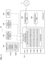
- FIG. 2 is a block diagram showing a detailed configuration of the host-vehicle device 1A.
- the configuration of the host-vehicle device 1A will be described below with reference to FIG. 2 .
- the host-vehicle device 1A includes a controller 11A, a camera unit 12A, a biological information sensor 13A, a travel information sensor 14A, and laser radars 15A as shown in FIG. 2 .
- the camera unit 12A has vehicle exterior cameras 121A and an in-vehicle camera 122A.
- the vehicle exterior cameras 121A captures the surrounding image of the host-vehicle VA.
- the in-vehicle camera 122A captures the face image of the driver of the host-vehicle VA.
- the vehicle exterior cameras 121A are installed at the front, rear, and left and right side portions of the host-vehicle VA, and captures the surrounding image of the host-vehicle VA, for example.
- the vehicle exterior cameras 121A transmits the captured image data to the controller 11A.
- An optical camera, charge-coupled device (CCD), complementary metal-oxide semiconductor (CMOS), and the like can be used as the vehicle exterior cameras 121A. If the host-vehicle VA is an automatic driving vehicle, the vehicle exterior cameras 121A may also be used as a camera for capturing a surrounding image used for automatic driving.
- the in-vehicle camera 122A is installed at the upper part of the windshield of the host-vehicle VA or a position in the vicinity of the instrument panel, and captures the face image of the driver, for example.
- the in-vehicle camera 122A transmits the captured image data to the controller 11A.
- an optical camera, CCD, CMOS, or the like can be used as the in-vehicle camera 122A.
- the biological information sensor 13A detects various pieces of biological information of the driver of the host-vehicle.
- the biological information sensor 13A include a heart rate sensor for measuring the heart rate per unit time of the driver, a breathing rate sensor for measuring the breathing rate per unit time of the driver, and a blood pressure sensor for measuring the blood pressure of the driver.
- the pieces of information obtained by the measurement by the biological information sensor 13A that is, the pieces of information on the heart rate, breathing rate, and blood pressure are transmitted to the controller 11A.
- the heart rate, breathing rate, and blood pressure are measured and detected without contact with the driver's body by using sensors embedded in the host-vehicle seat, for example.
- the travel information sensor 14A is a speed sensor and an acceleration sensor mounted on the host-vehicle VA, and transmits information on the detected speed and acceleration to the controller 11A, for example.
- the travel information sensor 14A also acquires information on the travelling road and lane on which the host-vehicle VA travels from a GPS receiver mounted on the host-vehicle VA. Specifically, if the host-vehicle VA travels on a traveling road having two or more lanes, the sensor acquires information indicating whether the lane on which the host-vehicle VA travels is a traveling lane or a passing lane.
- the travel information sensor 14A transmits information on the lane on which the host-vehicle travels to the controller 11A.
- the vehicle exterior cameras 121A, the in-vehicle camera 122A, the biological information sensor 13A, the travel information sensor 14A, and the laser radars 15A are an example of a host-vehicle information acquisition unit that acquires host-vehicle information.
- the laser radars 15A are lidars (laser imaging detection and ranging) mounted on the front side and the rear side of the host-vehicle, for example.
- the laser radars 15A emit the lasers toward the front position and the rear positon of the host-vehicle VA.
- the laser radars 15A receive the lasers reflected by a front vehicle and a rear vehicle and measure the distance between the host-vehicle and a preceding vehicle and the distance between the host-vehicle and a following vehicle.
- the laser radars 15A transmit information on the detected inter-vehicle distance to the controller 11A.
- the controller 11A includes a calculation processing unit 31A, a communication unit 32A (a host-vehicle side communication unit), and a presentation unit 33A.
- the controller 11A can be configured as an integrated computer including a central processing unit (CPU) and storage means such as an RAM, an ROM, and a hard disk, for example.
- CPU central processing unit
- storage means such as an RAM, an ROM, and a hard disk, for example.
- the calculation processing unit 31A includes an image recognition unit 311A, a danger degree determination unit 312A, an agitated degree calculation unit 313A, an agitating degree calculation unit 314A, and a storage unit 315A.
- the image recognition unit 311A recognizes the operation of the other-vehicles VB presenting in the individual directions of the front side, rear side, right side, and left side of the host-vehicle VA based on the surrounding image of the host-vehicle VA captured by means of the vehicle exterior cameras 121A.
- the image recognition unit 311A also acquires a face image of the driver captured by means of the in-vehicle camera 122A, analyzes the acquired face image, and detects the expression of the driver of the host-vehicle VA. Specifically, the image recognition unit 311A classifies driver's facial expressions into categories of anger, surprise, fear, sadness, fatigue, enjoyment, and criticism. A known technique can be employed for the method of analyzing the face image.
- the storage unit 315A stores the above described expression of the driver, various kinds of pieces of biological information detected by means of the biological information sensor 13A, travel information (information on speed and acceleration) of a vehicle detected by means of the travel information sensor 14A, information on the traveling lane, and information on the inter-vehicle distance detected by mean of the laser radars 15A. Further, the storage unit 315A stores information on the vehicle type of the host-vehicle VA.
- vehicle type is a concept that includes the classification of passenger vehicles and light vehicles, the classification of engine displacement, the classification of domestic and foreign vehicles, specific names of vehicle types, and specific vehicle numbers.
- the storage unit 315A stores an agitated degree correspondence table Tb1 for quantifying the degree to which the host-vehicle VA is agitated by the other-vehicles VB traveling around the host-vehicle VA.
- the quantification is performed based on the expression of the driver of the host-vehicle VA, the biological information of the driver, the travel information of the host-vehicle VA, the information on the traveling lane, the information on the inter-vehicle distance, and the information on a type of the host-vehicle VA.
- the agitated degree correspondence table Tb1 is also used for quantifying the degree to which the other-vehicles VB are agitated by the host-vehicle VA.
- the quantification is performed based on the expressions of the drivers of the other-vehicles VB, the pieces of biological information of the drivers, the pieces of travel information on the other-vehicle VB, the pieces of information on the traveling lanes, the pieces of information on the inter-vehicle distances, and the pieces of information on types of the other-vehicles VB.
- the storage unit 315A stores an agitating degree correspondence table Tb2 for quantifying the degree to which the host-vehicle VA agitates the driver of the other-vehicle VB.
- the quantification is performed based on the expression of the driver of the host-vehicle VA, the biological information of the driver, the travel information of the host-vehicle VA, the information on the traveling lane, the information on the inter-vehicle distance, and the information on a type of the host-vehicle VA.
- the agitating degree correspondence table Tb2 is also used for quantifying the degree to which the other-vehicle VB agitates the driver of the host-vehicle VA.
- the quantification is performed based on the expressions of the drivers of the other-vehicles VB, the pieces of biological information of the drivers, the pieces of travel information on the other-vehicle VB, the pieces of information on the traveling lanes, the pieces of information on the inter-vehicle distances, and the pieces of information on types of the other-vehicles VB.
- the storage unit 315A also stores a first evaluation value table TB1 and a second evaluation value table TB2.
- the first evaluation value table TB1 the degree to which the driver of the host-vehicle VA is agitated by the other-vehicles VB traveling around the host-vehicle VA (hereinafter referred to as an "agitated degree") is classified into four stages, and an evaluation value is set to each stage.
- the second evaluation value table TB2 the degree to which the host-vehicle VA agitates the driver of the other-vehicle VB traveling around the host-vehicle VA (hereinafter referred to as an "agitating degree") is classified into four stages, and an evaluation value is set to each stage. Details of each of the evaluation value tables TB1 and TB2 will be described later with reference to FIGS. 7A and 7B .
- the agitated degree calculation unit 313A calculates an agitated degree that is the degree to which the driver of the host-vehicle VA is agitated by the other-vehicles VB by referring to the agitated degree correspondence table Tb1 based on various kinds of pieces of biological information detected by means of the biological information sensor 13A of the host-vehicle device 1A, various kinds of pieces of vehicle information detected by means of the travel information sensor 14A, information on the traveling lane, and the inter-vehicle distance detected by means of the laser radars 15A.
- the agitated degree calculation unit 313A also calculates an agitated degree that is the degree to which the drivers of the other-vehicles VB are agitated by the host-vehicle VA by referring to the agitated degree correspondence table Tb1 based on various kinds of pieces of biological information detected by means of biological information sensors 13B of other-vehicle devices 1B, various kinds of pieces of vehicle information detected by means of travel information sensors 14B, pieces of information on the traveling lanes, and the inter-vehicle distances detected by means of laser radars 15B.
- the agitating degree calculation unit 314A calculates an agitating degree that is the degree to which the host-vehicle VA agitates the driver of the other-vehicle VB based on the biological information of the driver of the host-vehicle VA, the information on the host-vehicle VA, the information on the traveling lane, and the information on the inter-vehicle distance.
- the agitating degree calculation unit 314A calculates an agitating degree that is the degree to which the other-vehicles VB agitate the driver of the host-vehicle VA based on these pieces of information.
- the agitated degree, the agitating degree, and the calculation methods of these will be described later.
- the danger degree determination unit 312A determines the degree to which the driver of the host-vehicle VA is agitated by the other-vehicle VB (a first evaluation value Xp described later) and the degree to which the host-vehicle VA agitates the driver of the other-vehicle VB (a second evaluation value Yp described later) based on the agitating degree and the agitated degree.
- the communication unit 32A communicates with a server 3 via a network 4. Specifically, the communication unit 32A transmits, to the server 3, information on the expression of the driver of the host-vehicle VA recognized by means of the image recognition unit 311A, various kinds of pieces of biological information detected by means of the biological information sensor 13A, travel information on the host-vehicle VA detected by means of the travel information sensor 14A, information on the inter-vehicle distance detected by means of the laser radars 15A, and information on the traveling lane.
- the communication unit 32A also receives data transmitted from a communication unit 22 (described later) of the server 3.
- the communication unit 32A acquires the agitating degree indicating the degree to which the other-vehicle VB agitates the driver of the host-vehicle VA via the server 3 and the network 4.
- the presentation unit 33A is a display mounted in a vehicle, for example.
- the danger degree determination unit 312A determines that the driver of the host-vehicle VA is agitated by the other-vehicles VB, that the host-vehicle VA agitates the driver of the other-vehicle VB, or that the driver of the host-vehicle VA and the drivers of the other-vehicles VB are mutually agitated.
- the presentation unit 33A displays an image indicating a warning.
- the presentation unit 33A can also notify a user of a warning by using voice, light, vibration, and the like.
- the presentation unit 33A warns the host-vehicle VA of the danger degree due to the agitation action received from the other-vehicles VB.
- a warning is given to the host-vehicle by presenting a dangerous situation by using voice or text, such as "An agitation action is being received from a vehicle behind".
- a warning can be given to the host-vehicle by classifying the danger degree into numerical values of ten stages and the presenting in which stage, a current danger degree is in.
- the host-vehicle is warned of the danger degree by continuously changing the display color between "blue" and "red”.
- FIG. 3 is a block diagram showing a detailed configuration of an other-vehicle device 1B.
- the other-vehicle device 1B includes a controller 11B, a camera unit 12B having a vehicle exterior camera 121B and an in-vehicle camera 122B, a biological information sensor 13B, a travel information sensor 14B, and laser radars 15B as shown in FIG. 3 .
- the controller 11B includes a calculation processing unit 31B, a communication unit 32B (other-vehicle side communication unit), and a presentation unit 33B.
- the vehicle exterior camera 121B, the in-vehicle camera 122B, the biological information sensor 13B, the travel information sensor 14B, and the laser radars 15B are an example of an other-vehicle information acquisition unit for acquiring other-vehicle information.
- the other-vehicle devices 1B has the same configuration as the host-vehicle device 1A described above. Therefore, the suffix "A" of each component of the host-vehicle device 1A is replaced with "B" for the description of the other-vehicle devices 1B, and a detailed description thereof is omitted.
- FIG. 4 is a block diagram showing the configuration of the server 3 shown in FIG. 1 .
- the server 3 includes a control unit 21, a communication unit 22, and a storage unit 23 as shown in FIG. 3 .
- the communication unit 22 is connected to the host-vehicle device 1A and at least one other-vehicle device 1B via the network 4.
- the communication unit 22 communicates with the host-vehicle device 1A and at least one other-vehicle device 1B via the network 4.
- the storage unit 23 stores various kinds of pieces of data transmitted from the communication unit 32A of the host-vehicle device 1A and the communication unit 32B of the other-vehicle device 1B. Specifically, the storage unit 23 stores the expression of the driver, various kinds of pieces of biological information, travel information of the host-vehicle VA, information on the inter-vehicle distance, information on a type of the host-vehicle VA, and the like which are transmitted from the host-vehicle device 1A.
- the storage unit 23 stores the expression of the driver, various kinds of pieces of biological information, travel information of the other-vehicle VB, information on the inter-vehicle distance, information on type of the other-vehicle VB, and the like which are transmitted from the other-vehicle device 1B.
- the control unit 21 receives various kinds of pieces of information transmitted from the host-vehicle device 1A and the other-vehicle device 1B. Further, the control unit 21 performs the control to transmit the received various kinds of pieces of information to the host-vehicle device 1A and the other-vehicle device 1B.
- the control unit 21 performs the same processes as those of the danger degree determination unit 312A, the agitated degree calculation unit 313A, and the agitating degree calculation unit 314A described above.
- the control unit 21 can be configured as an integrated computer including a central processing unit (CPU) and storage means such as an RAM, an ROM, and a hard disk, for example.
- CPU central processing unit
- storage means such as an RAM, an ROM, and a hard disk, for example.
- FIGS. 5A and 5B show the agitated degree correspondence table Tb1 used for quantifying the agitated degree that is the degree to which the driver of the host-vehicle VA (or the other-vehicle VB) is agitated by the other-vehicle VB (or the host-vehicle VA).
- FIG. 5A shows a biological information table in which numerical values based on the biological information of the driver are set.
- FIG. 5B shows a vehicle information table in which numerical values based on the information of the host-vehicle VA are set.
- a heart rate [times/minute], a breathing rate [times/minute], a blood pressure (upper side) [mmHg], and a confidence level [%] of a facial expression (anger, sadness, or fatigue), and a score and a coefficient of each numerical value are set. If the heart rate of the driver of the host-vehicle VA is in the range from 75 to 80 [times/minute], the score is "1" and the coefficient is "2", for example. If the breathing rate of the driver is 40 [times/minute] or more, the score is "5" and the coefficient is "1.5".
- a speed of a host-vehicle [km/h] the number of sudden accelerations per unit time (in this case, 10 seconds), the degree of sudden accelerations (in this case, the change amount in speed per second [%]), the frequency of inattentive driving (in this case, the percentage of time in 1 minute during which the line of sight deviates 30 degrees or more from the front direction to an up-down direction and a right-left direction [%]), the number of sudden steering movements(in this case, the number of times per minute [times/minute]), and a score and a coefficient of each numerical value are set.
- the speed is in the range from 40 to 60 [km/h]
- the driver of the host-vehicle is less likely to be agitated by other-vehicles VB, and therefore the score is "0", for example.
- the score is "4" because the host-vehicle travels at the low speed and is likely to be agitated by other-vehicles, and the coefficient is set to 1.5.
- the score is "5" because the driver of the host-vehicle is more likely to be agitated by other-vehicles and the coefficient is set to 1.5.
- the higher the number of sudden accelerations per unit time for example, 10 seconds
- the higher the frequency of inattentive driving the higher the score. The higher the number of sudden steering movements, the higher the score.
- multiplication coefficients relative to information on a type of the host-vehicle VA are set in the range from “1" to "1.5". Further, the multiplication coefficient relative to information on the lane on which the host-vehicle is to travel is set to either "1" or "2.25".
- the multiplication coefficients are " ⁇ " and " ⁇ ”, which will be described later, and are coefficients used for calculating the agitated degree. Therefore, the larger the multiplication coefficient, the larger the value of the agitated degree.
- the information on a type of the host-vehicle VA can be classified depending on the size of the engine displacement of the host-vehicle and depending on whether the host-vehicle is a domestic vehicle or a foreign vehicle as described above, for example. As an example, if the host-vehicle is a foreign vehicle and the engine displacement of the host-vehicle is 2000 [cc] or more, the category is "A”. If the engine displacement is less than 2000 [cc], the category is "B".
- the category is "C”
- the category is "D”
- the category is "E”
- the category is "F”.
- the multiplication coefficient is set to be high.
- a foreign vehicle with a large engine displacement is less likely to be agitated, and therefore, the multiplication coefficient is set to be low.
- the lane information indicates whether the host-vehicle VA is traveling on the traveling lane or on the passing lane. If the host-vehicle VA is continuously traveling on the traveling lane, the multiplication coefficient is set to "1". If the host-vehicle VA is traveling on the passing lane for 30 seconds or longer between the current time and the time backward by 5 minutes from the current time, the multiplication coefficient is "2.25", for example. That is, if the host-vehicle VA is traveling on the passing lane, the possibility that the driver of the host-vehicle is agitated by the other-vehicles VB increases, and therefore the multiplication coefficient is set to be high. If the host-vehicle VA travels on a single-lane road on either side, the multiplication coefficient is "1".
- the scores, coefficients, and multiplication coefficients described above are used in an arithmetic expression (described later) for calculating the agitated degree and the agitating degree.
- the agitated degree correspondence table Tb1 stored in the storage unit 315A mounted on the host-vehicle device 1A has been described.
- the similar agitated degree correspondence table Tb1 is also stored in a storage unit 315B mounted on the other-vehicle device 1B.
- FIGS. 6A and 6B show an agitating degree correspondence table Tb2 used for quantifying an agitating degree that is the degree to which the host-vehicle VA (or other-vehicle VB) agitates the driver of the other-vehicle VB (or the host-vehicle VA).
- FIG. 6A shows a biological information table in which numerical values based on the biological information of the driver are set.
- FIG. 6B shows a vehicle information table in which numerical values based on the information on the host-vehicle are set.
- a heart rate [times/minute], a breathing rate [times/minute], a blood pressure (upper side) [mmHg], and a confidence level [%] of facial expression (anger), and a score and a coefficient of each numerical value are set. If the heart rate is in the range from 75 to 80 [times/minute], the score is "1" and the coefficient is "2", for example. Further, if the breathing rate is 40 [times/minute] or more, the score is "5" and the coefficient is "1.5".
- a speed of a host-vehicle [km/h] the number of sudden accelerations per unit time (in this case, 10 seconds), the degree of sudden accelerations (in this case, the change amount in speed per second [%]), the frequency of inattentive driving (in this case, the percentage of time in 1 minute during which the line of sight deviates 30 degrees or more from the front direction to an up-down direction and a right-left direction [%]), and the number of sudden steering movements(in this case, the number of times per minute [times/minute]), and a score and a coefficient of each numerical value are set.
- the number of sudden accelerations per unit time in this case, 10 seconds
- the degree of sudden accelerations in this case, the change amount in speed per second [%]
- the frequency of inattentive driving in this case, the percentage of time in 1 minute during which the line of sight deviates 30 degrees or more from the front direction to an up-down direction and a right-left direction [%]
- the number of sudden steering movements in this case
- the score is "1" and the coefficient is "1.5", for example. If the number of sudden acceleration is 5 times or more times during 10 seconds, the score is set to "5" and the coefficient is set to "2".
- the multiplication coefficients relative to the vehicle type information and the vehicle body information of the host-vehicle VA are set in the range from "1" to "1.5” individually.
- the information on a type of the host-vehicle VA can be classified depending on the size of the engine displacement of the host-vehicle and depending on whether the host-vehicle is a domestic vehicle or a foreign vehicle.
- the category is "A”
- the category is "B”
- the category is "C”
- the category is "D”
- the category is "E”
- the engine displacement is 2000 [cc] or more
- a multiplication coefficient is set to be high.
- a domestic vehicle with a small engine displacement, such as a light vehicle is less likely to perform an agitation action, and therefore, a multiplication coefficient is set to be low.
- the vehicle body information is information on violation history and accident history in the past. If the number of past violations and accidents is zero, the category is "A", and as the number of past violations and accidents increases, the category is changed to "B", "C", “D”, "E”, and “F” in this order. That is, it is considered that a vehicle that caused a large number of violations and accidents in the past is likely to agitate other-vehicles. Therefore, the higher the number of violations and accidents, the higher the multiplication coefficient is set.
- the multiplication coefficient is set to be high for a vehicle type that caused a large number of violations and accidents in the past, for example. In addition, the multiplication coefficient is set to be high for a vehicle of a vehicle number that caused a large number of violations and accidents in the past.
- the lane information indicates whether the host-vehicle VA is traveling on the traveling lane or on the passing lane.
- the multiplication coefficient is set to "1" if the host-vehicle VA is continuously traveling on the traveling lane, for example.
- the multiplication coefficient is set to "1.5” if the host-vehicle VA is traveling on the passing lane for 30 seconds or longer between the current time and the time backward by 5 minutes from the current time. That is, if the host-vehicle VA is traveling on the passing lane, the possibility that the host-vehicle agitates the drivers of the other-vehicles VB increases, and therefore, the multiplication coefficient is set to be high. If the host-vehicle VA travels on a single-lane road on either side, the multiplication coefficient is "1". Further, the larger the number of other-vehicles travelling around the host-vehicle, the higher the multiplication coefficient may be set.
- the scores, coefficients, and multiplication coefficients described above are used in an arithmetic expression (described later) for calculating the agitated degree and the agitating degree.
- the agitating degree correspondence table Tb2 stored in the storage unit 315A mounted on the host-vehicle device 1A has been described.
- the similar agitating degree correspondence table Tb2 is also stored in the storage unit 315B mounted on the other-vehicle device 1B.
- the agitated degree correspondence table Tb1 shown in FIGS. 5A and 5B is used to calculate the agitated degree (this is referred to as "Q1") when the driver of the host-vehicle VA is agitated by the other-vehicle VB.
- the agitating degree correspondence table Tb2 shown in FIGS. 6A and 6B is used to calculate the agitating degree (this is referred to as "Q2") when the other-vehicle VB agitates the driver of the host-vehicle VA.
- an evaluation value of the danger degree due to the agitation action received by the host-vehicle VA from the other-vehicle VB is calculated and an evaluation value of the danger degree due to the agitation action performed by the other-vehicle VB against the host-vehicle VA is calculated.
- the warning in accordance with each evaluation value is presented to the driver of the host-vehicle VA. Details of the "evaluation value" will be described later.
- the agitated degree Q1 when the driver of the other-vehicle VB is agitated by the host-vehicle VA is calculated by using the agitated degree correspondence table Tb1.
- the agitating degree Q2 when the host-vehicle VA agitates the driver of the other-vehicle VB is calculated by using the agitating degree correspondence table Tb2.
- an evaluation value of the danger degree due to the agitation action received by the other-vehicle VB from the host-vehicle VA is calculated and an evaluation value of the danger degree due to the agitation action performed by the host-vehicle VA against the other-vehicle VB is calculated.
- the warning in accordance with each evaluation value is presented to the driver of the host-vehicle VA.
- the agitating degree correspondence table Tb2 is used to calculate the agitating degree Q2 (first agitating degree) when the host-vehicle VA agitates the driver of the other-vehicle VB and the agitating degree Q2' (second agitating degree) when the other-vehicle VB agitates the driver of the host-vehicle VA.
- an evaluation value of the danger degree due to the agitation action performed by the other-vehicle VB against the host-vehicle VA is calculated and an evaluation value of the danger degree due to the agitation action performed by the host-vehicle VA against the other-vehicle VB is calculated.
- the warning in accordance with each evaluation value is presented to the driver of the host-vehicle VA.
- an agitated degree calculation unit 313A refers to the agitated degree correspondence table Tb1 described to calculate the agitated degree Q1 when the driver of the host-vehicle VA is agitated by the other-vehicle VB.
- the agitated degree calculation unit 313A calculates a parameter q1 by using the following equation (1) based on a score and a coefficient of each item shown in FIGS. 5A and 5B .
- q1 (heart rate score) * 2 + (breathing rate score) * 1.5 + (blood pressure score) * 2 + (facial expression score) * 1.5 + (speed score) * 1.5 + (score of number of sudden accelerations) * 2 + (score of sudden acceleration degree) * 1.5 + (frequency of inattentive driving) * 1.5 + (number of sudden steering movements) * 2
- the parameter q1 is multiplied by a multiplication coefficient in accordance with the information on a type of the host-vehicle VA (this is referred to as " ⁇ ") and a score in accordance with the lane information (this is referred to as " ⁇ ") in the following equation (2), and thus the agitated degree Q1 is calculated.
- the ⁇ is a numerical value in the range from 1 to 1.5 and the ⁇ is a numerical value of either one of 1 and 2.25.
- Q1 ⁇ * ⁇ * q1
- the agitated degree Q1 takes a numerical value in the range from 0 to 261.6.
- an agitating degree calculation unit 314A refers to the agitating degree correspondence table Tb2 shown in FIGS. 6A and 6B to calculate the agitating degree Q2 when the host-vehicle VA agitates the driver of the other-vehicle VB.
- the agitating degree calculation unit 314A calculates a parameter q2 by using the following equation (3) based on the scores and coefficients shown in FIGS. 6A and 6B .
- q2 (heart rate score) * 2 + (breathing rate score) * 1.5 + (blood pressure score) * 2 + (facial expression score) * 1.5 + (speed score) * 1.5 + (score of number of sudden accelerations) * 2 + (score of sudden accelaration degree) * 1.5 + (frequency of inattentive driving) * 1.5 + (number of sudden streering movements) * 2
- the parameter q2 is multiplied by the score in accordance with the information on a type of the host-vehicle VA (this is referred to as " ⁇ "), the score in accordance with the vehicle body information (this is referred to as " ⁇ "), and the score in accordance with the lane information (this is referred to as " ⁇ ") in the following equation (4), and thus, the agitating degree Q2 is calculated.
- the ⁇ and ⁇ are numerical values in the range from 1 to 1.5 and ⁇ is a numerical value of either one of 1 and 1.5.
- Q2 ⁇ * ⁇ * ⁇ * q2
- the agitating degree Q2 is a numerical value in the range from 0 to 261.6.
- the storage unit 315A shown in FIG. 2 stores a first evaluation value table and a second evaluation value table.
- the agitated degree Q1 of an agitation action received by the host-vehicle VA from the other-vehicle VB is classified into four stages and an evaluation value is set for each stage.
- the agitating degree Q2 of an agitation action performed by the host-vehicle VA against the other-vehicle VB is classified into four stages and an evaluation value is set for each stage.
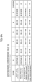
- FIG. 7A shows a first evaluation value table TB1.
- the relationship between the agitated degree Q1 which changes in the range from "0 to 202.5" and the evaluation value Xp is set.
- the agitated degree Q1 is classified into four stages, and as evaluation values Xp for the four stages, X0 to X3 are set. If the agitated degree Q1 is in the range from 0 to 50, the evaluation value Xp is X0, for example.
- FIG. 7B shows the second evaluation value table TB2.
- the relationship between the agitating degree Q2 which changes in the range from "0 to 202.5" and the evaluation value Yp is set.
- the agitating degree Q2 is classified into four stages, and as evaluation values Yp for the four stages, Y0 to Y3 are set. If the agitating degree Q2 is 150 or more, the evaluation value Yp is Y3, for example.
- the danger degree determination unit 312A determines an evaluation value Xp (this is defined as a first evaluation value Xp) by referring to the first evaluation value table TB1 based on the agitated degree Q1.
- the danger degree determination unit 312A determines an evaluation value Yp (this is defined as a second evaluation value Yp) by referring to the second evaluation value table TB2 based on the agitating degree Q2.
- the danger degree determination unit 312A determines the warning content given to the driver of the host-vehicle VA (see FIGS. 8A and 8B ) based on the determined first evaluation value Xp and second evaluation value Yp and outputs the content to the presentation unit 33A.
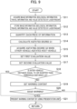
- FIG. 9 is a flowchart showing a processing procedure of the dangerous driving warning system 101 according to the first embodiment.
- the controller 11A acquires various pieces of information detected by means of the camera unit 12A, the biological information sensor 13A, the travel information sensor 14A, and the laser radars 15A mounted on the host-vehicle device 1A.
- step S12 the controller 11A stores various pieces of information acquired through the process of step S11 in the storage unit 315A.
- step S13 the agitated degree calculation unit 313A refers to the agitated degree correspondence table Tb1 and quantifies the above various pieces of information. As shown in FIG. 5B , if the traveling speed of the host-vehicle VA is in the range from 60 to 70 [km/h], the score is "1", for example.
- the agitated degree calculation unit 313A calculates the agitated degree Q1. Specifically, the agitated degree calculation unit 313A calculates the agitated degree Q1, which is the degree to which the driver of the host-vehicle VA is agitated by the other-vehicle VB by using the above described equation (2).
- the agitated degree Q1 can be calculated by using the numerical value at the determination time (instantaneous). Further, in addition to the above, it is possible to set a time zone that is backward by a predetermined time (for example, 10 seconds) from the determination time and to use representative values such as an average value, a peak value, and a median value of the agitated degree Q1 during the time zone, for example. Further, it is possible to hold the peak value during the time zone for a predetermined time (for example, 10 seconds) to obtain the agitated degree Q1.
- a predetermined time for example, 10 seconds
- step S15 the communication unit 32A acquires the data of the agitating degree Q2 calculated by means of the other-vehicle device 1B.
- the agitating degree calculation unit 314B of the other-vehicle device 1B calculates the agitating degree Q2 when the other-vehicle VB agitates the driver of the host-vehicle VA.
- the agitating degree Q2 is calculated by using the above described equation (4).
- the data of the agitating degree Q2 is transmitted to the server 3 via the network 4, and further transmitted to the host-vehicle device 1A.
- the communication unit 32A receives the data of the agitating degree Q2.
- the agitating degree Q2 can be calculated by using a numerical value at the determination time (instantaneous) in the same manner as the agitated degree Q1 described above.
- a time zone that is backward by a predetermined time (for example, 10 seconds) from the determination time and to use representative values such as an average value, a peak value, and a median value of the agitating degree Q2 during the time zone. It is also possible to hold the peak value during the time zone for a predetermined time (for example, 10 seconds) to obtain the agitating degree Q2.
- step S16 the danger degree determination unit 312A sets the first evaluation value Xp based on the agitated degree Q1 calculated in the process of step S14. Specifically, the danger degree determination unit 312A sets any one of X0 to X3 shown in FIG. 7A as the first evaluation value Xp.
- step S17 the danger degree determination unit 312A sets the second evaluation value Yp based on the agitating degree Q2 obtained in the process of step S15. Specifically, the danger degree determination unit 312A sets any one of Y0 to Y3 shown in FIG. 7B as the second evaluation value Yp.
- step S18 the danger degree determination unit 312A, based on the distance between the host-vehicle VA and the other-vehicle VB, determines whether the inter-vehicle distance is equal to or shorter than a preset threshold distance Lth. If the inter-vehicle distance is equal to or shorter than the threshold distance Lth (S18; YES), the process proceeds to step S21. Alternatively, if the inter-vehicle distance is longer than the threshold distance Lth, (S18); NO), the process proceeds to step S19.
- step S19 the danger degree determination unit 312A sets the warning content given to the driver of the host-vehicle VA based on the first evaluation value Xp and the second evaluation value Yp.
- the danger degree determination unit 312A determines the warning content in accordance with the first evaluation value Xp under the condition that the second evaluation value Yp is Y1 or above, for example.
- FIG. 8A shows the warning content when the driver of the host-vehicle VA is agitated by the other-vehicle VB.
- "No warning" is set as the content when the first evaluation value Xp is X0.
- the first evaluation value Xp is in the range from X1 to X3, warning content in accordance with each evaluation value is set.
- step S20 the danger degree determination unit 312A determines whether to warn the driver of the host-vehicle VA that the driver of the host-vehicle VA is agitated. If the second evaluation value Yp is Y0 or the first evaluation value Xp is X0, the danger degree determination unit 312A makes no warning to the driver (S20; NO), and therefore the process ends.
- the danger degree determination unit 312A presents the warning content in accordance with the first evaluation value Xp by using the presentation unit 33A.
- the presentation unit 33A is a display
- the presentation unit 33A displays the text such as "Please drive safely", for example.
- the presentation unit 33A displays the text such as "Please travel carefully”, for example.
- the presentation unit 33A displays the text such as "Dangerous driving has been detected. Please pay attention to surrounding vehicles", for example. That is, the higher the first evaluation value Xp is, the stronger the calling for attention is.
- the presentation unit 33A presents content such as "There is an abnormally close vehicle. Please be careful.” by using text or voice. That is, if the inter-vehicle distance is short and the other-vehicle VB is abnormally close to the host-vehicle VA, the warning is displayed regardless of the magnitude of the agitated degree Q1. Thereafter, the process ends.
- the dangerous driving warning system 101 according to the first embodiment can achieve the following effects.
- the control unit 21 of the server 3 shown in FIG. 4 is configured to include a danger degree determination unit similar to the danger degree determination unit 312A.
- the first modified example of the first embodiment differs from the first embodiment described above in that the storage unit 23 of the server 3 stores the agitated degree correspondence table Tb1, the agitating degree correspondence table Tb2, the first evaluation value table TB1, and the second evaluation value table TB2.
- various kinds of pieces of information detected by means of the host-vehicle device 1A are transmitted from the communication unit 32A to the server 3 via the network 4. Then, the control unit 21 of the server 3 calculates the agitated degree Q1. Further, various kinds of pieces of information detected by means of the other-vehicle device 1B are transmitted from the communication unit 32B to the server 3 via the network 4. Then, the control unit 21 of the server 3 calculates the agitating degree Q2.
- Other configurations other than the above are the same as those of the first embodiment described above.
- the agitated degree correspondence table Tb1 and the agitating degree correspondence table Tb2 are provided in the server 3.
- the agitated degree Q1 and the agitating degree Q2 are calculated in the server 3. Accordingly, it is possible to reduce the storage capacity and the calculation load of the storage units 315A and 315B mounted on the host-vehicle device 1A and the other-vehicle device 1B respectively.
- the agitating degree calculation unit 314B mounted on the other-vehicle VB is configured to calculate the agitating degree Q2 of an agitation action performed by the other-vehicle VB against the host-vehicle VA and transmit the calculated agitating degree Q2 to the host-vehicle VA via the network 4.
- various kinds of pieces of information detected by means of the other-vehicle device 1B are transmitted to the host-vehicle device 1A via the network 4.
- the difference between the second modified example of the first embodiment and the first embodiment resides in that the agitating degree calculation unit 314A mounted on the host-vehicle device 1A calculates the agitating degree Q2 of an agitation action performed by the other-vehicle VB.
- step S31 of FIG. 10 the controller 11A mounted on the host-vehicle device 1A acquires various pieces of information detected by means of the camera unit 12A, the biological information sensor 13A, the travel information sensor 14A, and the laser radars 15A.
- step S32 the controller 11A stores various pieces of information acquired in the process of step S31 in the storage unit 315A.
- step S33 the agitated degree calculation unit 313A refers to the agitated degree correspondence table Tb1 and quantifies the various pieces of information described above.
- step S34 the controller 11A of the host-vehicle device 1A acquires various pieces of information detected by means of the camera unit 12B, the biological information sensor 13B, the travel information sensor 14B, and the laser radars 15B mounted on the other-vehicle device 1B.
- the communication unit 32A of the host-vehicle device 1A receives various kinds of pieces of data transmitted from the communication unit 32B of the other-vehicle device 1B.
- step S35 the controller 11A stores the various pieces of information acquired in the process of step S34 in the storage unit 315A.
- step S36 the agitating degree calculation unit 314A refers to the agitating degree correspondence table Tb2 and quantifies the above described various pieces of information.
- the agitated degree calculation unit 313A calculates the agitated degree Q1. Specifically, the agitated degree calculation unit 313A calculates the agitated degree Q1, which is the degree to which the driver of the host-vehicle VA is agitated by the other-vehicle VB by using the above described equation (2).
- the agitated degree Q1 can be calculated by using the numerical value at the determination time (instantaneous). In addition to the above, it is possible to set a time zone that is backward by a predetermined time (for example, 10 seconds) from the determination time and to use representative values such as an average value, a peak value, and a median value of the agitated degree Q1 during the time zone. It is also possible to hold the peak value during the time zone for a predetermined time (for example, 10 seconds) to obtain the agitated degree Q1.
- a predetermined time for example, 10 seconds
- the agitating degree calculation unit 314A calculates the agitating degree Q2. Specifically, the agitating degree calculation unit 314A calculates the agitating degree Q2 when the other-vehicle VB agitates the driver of the host-vehicle VA by using the above described equation (4).
- the agitating degree Q2 can be calculated by using the numerical value at the determination time (instantaneous). In addition to the above, it is also possible to set a time zone that is backward by a predetermined time (for example, 10 seconds) from the determination time, and to use representative values such as an average value, a peak value, and a median value of the agitating degree Q2 during the time zone. It is also possible to hold the peak value during the time zone for a predetermined time (for example, 10 seconds) to obtain the agitating degree Q2.
- a predetermined time for example, 10 seconds
- step S39 the danger degree determination unit 312A sets the first evaluation value Xp based on the agitated degree Q1 calculated in the process of step S37. Specifically, the danger degree determination unit 312A sets an evaluation value of any one of X0 to X3 shown in FIG. 7A as the first evaluation value Xp.
- step S40 the danger degree determination unit 312A sets the second evaluation value Yp based on the agitating degree Q2 obtained in the process of step S38. Specifically, the danger degree determination unit 312A sets an evaluation value of any one of Y0 to Y3 shown in FIG. 7B as the second evaluation value Yp.
- steps S41 to S44 are the same as the processes of steps S18 to S21 shown in FIG. 9 , description thereof is omitted.
- the agitated degree calculation unit 313A of the host-vehicle device 1A calculates the agitated degree Q1 when the driver of the host-vehicle VA is agitated by the other-vehicle VB.
- the agitating degree calculation unit 314A acquires various kinds of pieces of information on the other-vehicle VB from the other-vehicle VB, and calculates the agitating degree Q2 when the other-vehicle VB agitates the driver of the host-vehicle VA by using the acquired pieces of information.
- the agitated degree Q1 and the agitating degree Q2 can be calculated by means of the host-vehicle device 1A, the calculation load in the other-vehicle VB can be reduced.
- a dangerous driving warning system 101 according to the second embodiment is the same as the dangerous driving warning system 101 shown in FIGS. 1 to 4 described above, a description of the configuration thereof is omitted.
- the driver of the host-vehicle VA is warned of the danger degree caused by the driver performing the agitation action.
- step S51 of FIG. 11 the controller 11A acquires various pieces of information detected by means of a camera unit 12A, a biological information sensor 13A, a travel information sensor 14A, and laser radars 15A mounted on a host-vehicle device 1A.
- step S52 the controller 11A stores the various pieces of information acquired in the process of step S51 in a storage unit 315A.
- step S53 the agitating degree calculation unit 314A refers to the agitating degree correspondence table Tb2 and quantifies the above described various pieces of information. As shown in FIG. 6B , if the number of accelerations of the host-vehicle VA is five times or more in 10 seconds, the score is "5", for example.
- the agitating degree calculation unit 314A calculates the agitating degree Q2. Specifically, the agitating degree calculation unit 314A calculates the agitating degree Q2 when the host-vehicle VA agitates the driver of the other-vehicle VB by using the above described equation (4).
- the agitating degree Q2 can be calculated by using the numerical value at the determination time (instantaneous). In addition to the above, it is also possible to set a time zone that is backward by a predetermined time (for example, 10 seconds) from the determination time, and to use representative values such as an average value, a peak value, and a median value of the agitating degree Q2 during the time zone. It is also possible to hold the peak value during the time zone for a predetermined time (for example, 10 seconds) to obtain the agitating degree Q2.
- a predetermined time for example, 10 seconds
- step S55 the communication unit 32A acquires data of the agitated degree Q1 calculated by means of the other-vehicle device 1B.
- the agitated degree calculation unit 313B of the other-vehicle device 1B calculates the agitated degree Q1 when the driver of the other-vehicle VB is agitated by the host-vehicle VA.
- the agitated degree Q1 is calculated by using the above described equation (2).
- the data of the agitated degree Q1 is transmitted to the server 3 via the network 4, and further transmitted to the host-vehicle device 1A.
- the communication unit 32A receives the data of the agitated degree Q1.
- the agitated degree Q1 can be calculated by using the numerical value at the determination time (instantaneous). In addition to the above, it is also possible to set a time zone that is backward by a predetermined time (for example, 10 seconds) from the determination time, and to use representative values such as an average value, a peak value, and a median value of the agitated degree Q1 during the time zone. It is also possible to hold the peak value during the time zone for a predetermined time (for example, 10 seconds) to obtain the agitated degree Q1.
- a predetermined time for example, 10 seconds
- step S56 the danger degree determination unit 312A sets the first evaluation value Xp based on the agitated degree Q1 acquired in the process of step S55. Specifically, the danger degree determination unit 312A sets an evaluation value of any one of X0 to X3 shown in FIG. 7A as the first evaluation value Xp.
- step S57 the danger degree determination unit 312A sets the second evaluation value Yp based on the agitating degree Q2 calculated in the process of step S54. Specifically, the danger degree determination unit 312A sets an evaluation value of any one of Y0 to Y3 shown in FIG. 7B as the second evaluation value Yp.
- step S58 the danger degree determination unit 312A determines, based on the distance between the host-vehicle VA and the other-vehicle VB, whether the inter-vehicle distance is equal to or shorter than a preset threshold distance Lth. If the inter-vehicle distance is equal to or shorter than the the threshold distance Lth (S58; YES), the process proceeds to step S61. If the inter-vehicle distance is longer than the threshold distance Lth (S58; NO), the process proceeds to step S59.
- step S59 the danger degree determination unit 312A sets the warning content given to the driver of the host-vehicle VA based on the first evaluation value Xp and the second evaluation value Yp.
- the danger degree determination unit 312A determines the warning content in accordance with the second evaluation value Yp under the condition that the first evaluation value Xp is X1 or above, for example.
- FIG. 8B shows the warning content when the host-vehicle VA agitates the driver of the other-vehicle VB.
- "No warning" is set as the content when the second evaluation value Yp is Y0. Further, when the second evaluation value Yp is in the range from Y1 to Y3, warning content in accordance with each evaluation value is set.
- step S60 the danger degree determination unit 312A determines whether to warn the driver of the host-vehicle VA that the host-vehicle VA is performing an agitation action. If the first evaluation value Xp is X0 or the second evaluation value Yp is Y0, no warning is made (S60; NO), and therefore the process ends.
- the danger degree determination unit 312A presents the warning in accordance with the second evaluation value Yp by using the presentation unit 33A.
- the presentation unit 33A is a display
- the display displays the text such as "Please drive safely”.
- the display displays the text such as "Please travel carefully”, for example.
- the display displays the text such as "Dangerous driving has been detected. Please adopt a safe inter-vehicle distance", for example.
- the inter-vehicle distance becomes equal to or shorter than the threshold distance Lth (S58; YES)
- content such as "We are abnormally close to a preceding vehicle. Please drive by adopting a sufficient distance with the preceding vehicle.” is presented by using text or voice, for example. That is, if the inter-vehicle distance is short and the host-vehicle VA is abnormally close to the other-vehicle VB, the warning is displayed regardless of the magnitude of the agitating degree Q2. Thereafter, the process ends.
- a control unit 21 of a server 3 shown in FIG. 4 is configured to include a danger degree determination unit.
- the first modified example of the second embodiment differs from the second embodiment in that, in the first modified example, a storage unit 23 of the server 3 stores an agitated degree correspondence table Tb1, an agitating degree correspondence table Tb2, a first evaluation value table TB1, and a second evaluation value table TB2.
- various kinds of pieces of information detected by means of the host-vehicle device 1A are transmitted from the communication unit 32A to the server 3 via the network 4. Then, the control unit 21 of the server 3 calculates the agitating degree Q2. Further, various kinds of pieces of information detected by means of the other-vehicle device 1B are transmitted from the communication unit 32B to the server 3 via the network 4. Then, the control unit 21 of the server 3 calculates the agitated degree Q1. Configurations other than the above are the same as those in the second embodiment described above.
- the agitated degree correspondence table Tb1 and the agitating degree correspondence table Tb2 are stored in the server 3, and the server 3 calculates the agitating degree Q2 and the agitated degree Q1. This can reduce the storage capacity and the calculation load of the storage units 315A and 315B mounted on the host-vehicle device 1A and the other-vehicle device 1B respectively.
- the agitated degree calculation unit 313B mounted on the other-vehicle VB calculates the agitated degree Q1 of an agitation action performed by the host-vehicle VA against the other-vehicle VB, and transmits the calculated agitated degree Q1 to the host-vehicle VA via the network 4.
- the second modified example of the second embodiment differs from the second embodiment in that, in the second modified example, various kinds of pieces of information detected by means of the other-vehicle device 1B are transmitted to the host-vehicle device 1A via the network 4, and then the calculation processing unit 31A mounted on the host-vehicle device 1A calculates the agitated degree Q1 of an agitation action performed against the other-vehicle VB.
- step S71 of FIG. 12 the controller 11A acquires various pieces of information detected by means of the camera unit 12A, the biological information sensor 13A, the travel information sensor 14A, and the laser radars 15A mounted on the host-vehicle device 1A.
- step S72 the controller 11A stores the various pieces of information acquired in the process of step S71 in the storage unit 315A.
- step S73 the agitated degree calculation unit 313A refers to the agitated degree correspondence table Tb1 and quantifies the above described various pieces of information.
- step S74 the controller 11A acquires various pieces of information detected by means of the camera unit 12B, the biological information sensor 13B, the travel information sensor 14B, and the laser radars 15B mounted on the other-vehicle device 1B.
- the communication unit 32A of the host-vehicle device 1A receives the various kinds of pieces of data transmitted from the communication unit 32B of the other-vehicle device 1B.
- step S75 the controller 11A stores the various pieces of information acquired in the process of step S74 in the storage unit 315A.
- step S76 the agitating degree calculation unit 314A refers to the agitating degree correspondence table Tb2 and quantifies the above described various pieces of information.
- the agitating degree calculation unit 314A calculates the agitating degree Q2. Specifically, the agitating degree calculation unit 314A calculates the agitating degree Q2 when the host-vehicle VA agitates the driver of the other-vehicle VB by using the above described equation (4).
- the agitating degree Q2 can be calculated by using the numerical value at the determination time (instantaneous). In addition to the above, it is also possible to set a time zone that is backward by a predetermined time (for example, 10 seconds) from the determination time, and to use representative values such as an average value, a peak value, and a median value of the agitating degree Q2 during the time zone. It is also possible to hold the peak value during the time zone for a predetermined time (for example, 10 seconds) to obtain the agitating degree Q2.
- a predetermined time for example, 10 seconds
- the agitated degree calculation unit 313A calculates the agitated degree Q1. Specifically, the agitated degree calculation unit 313A calculates the agitated degree Q1 when the driver of the other-vehicle VB is agitated by the host-vehicle VA by using the above described equation (2).
- the agitated degree Q1 can be calculated by using the numerical value at the determination time (instantaneous). In addition to the above, it is also possible to set a time zone that is backward by a predetermined time (for example, 10 seconds) from the determination time, and to use representative values such as an average value, a peak value, and a median value of the agitated degree Q1 during the time zone. It is also possible to hold the peak value during the time zone for a predetermined time (for example, 10 seconds) to obtain the agitated degree Q1.
- a predetermined time for example, 10 seconds
- step S79 the danger degree determination unit 312A sets the first evaluation value Xp based on the agitated degree Q1 acquired in the process of step S78. Specifically, the danger degree determination unit 312A sets an evaluation value of any one of X0 to X3 shown in FIG. 7A as the first evaluation value Xp.
- step S80 the danger degree determination unit 312A sets the second evaluation value Yp based on the agitating degree Q2 calculated in the process of step S77. Specifically, the danger degree determination unit 312A sets an evaluation value of any one of Y0 to Y3 shown in FIG. 7B as the second evaluation value Yp.
- steps S81 to S84 are the same as the processes in steps S58 to S61 shown in FIG. 11 , description thereof is omitted.
- the host-vehicle VA calculates the agitating degree Q2 when the host-vehicle VA agitates the driver of the other-vehicle VB. Further, the host-vehicle VA receives various kinds of pieces of information on the other-vehicle VB from the other-vehicle VB, and calculates the agitated degree Q1 when the driver of the other-vehicle VB is agitated by the host-vehicle VA by using the acquired information.
- the host-vehicle device 1A can calculate the agitating degree Q2 and the agitated degree Q1. This can reduce the calculation load of the other-vehicle device 1B.
- a dangerous driving warning system 101 according to the third embodiment is the same as the dangerous driving warning system 101 shown in FIGS. 1 to 4 described above, a configuration description thereof is omitted.
- the agitating degree calculation unit 314A shown in FIG. 2 is a first agitating degree calculation unit for calculating the agitating degree Q2 (a first agitating degree) indicating the degree to which the host-vehicle VA agitates the driver of the other-vehicle VB.
- the agitating degree calculation unit 314B shown in FIG. 3 is a second agitating degree calculation unit for calculating the agitating degree Q2' (a second agitating degree) indicating the degree to which the other-vehicle VB agitates the driver of the host-vehicle VA.
- the driver of the host-vehicle VA and the driver of the other-vehicle VB agitate each other, the driver of at least one of the host-vehicle VA and the other-vehicle VB is warned of the danger degree caused by performing the agitation action.
- the second embodiment shows countermeasures when the host-vehicle VA agitates the driver of the other-vehicle VB.
- the third embodiment when the driver of the host-vehicle VA and the driver of the other-vehicle VB agitate each other, processes are performed for warning the driver of at least one of the host-vehicle VA and the other-vehicle VB.
- step S91 of FIG. 13 the controller 11A acquires various pieces of information detected by means of the camera unit 12A, the biological information sensor 13A, the travel information sensor 14A, and the laser radars 15A mounted on the host-vehicle device 1A.
- step S92 the controller 11A stores the various pieces of information acquired in the process of step S91 in the storage unit 315A.
- step S93 the agitating degree calculation unit 314A (a first agitating degree calculation unit) refers to the agitating degree correspondence table Tb2 and quantifies the above described various pieces of information. As shown in FIG. 6B , if the number of accelerations of the host-vehicle VA is 5 times or more in 10 seconds, the score is "5", for example.
- the agitating degree calculation unit 314A calculates the agitating degree Q2 (a first agitating degree) . Specifically, the agitating degree calculation unit 314A calculates a first agitating degree Q2, which is the degree to which the host-vehicle VA agitates the driver of the other-vehicle VB by using the above described equation (4).
- the first agitating degree Q2 can be calculated by using the numerical value at the determination time (instantaneous).
- a time zone that is backward by a predetermined time (for example, 10 seconds) from the determination time, and to use representative values such as an average value, a peak value, and a median value of the first agitating degree Q2 during the time zone. It is also possible to hold the peak value during the time zone for a predetermined time (for example, 10 seconds) to obtain the first agitating degree Q2.
- step S95 the communication unit 32A acquires data of the agitating degree calculated by means of the agitating degree calculation unit 314B (a second agitating degree calculation unit) of the other-vehicle device 1B (a second agitating degree; this is denoted with "Q2'").
- the agitating degree calculation unit 314B of the other-vehicle device 1B calculates the second agitating degree Q2' when the other-vehicle VB agitates the driver of the host-vehicle VA.
- the second agitating degree Q2' is calculated by using the above described equation (4).
- the data of the second agitating degree Q2' is transmitted to the server 3 via the network 4, and further transmitted to the host-vehicle device 1A.
- the communication unit 32A receives the data of the second agitating degree Q2'.
- the second agitating degree Q2' can be calculated by using the numerical value at the determination time (instantaneous). In addition to the above, it is also possible to set a time zone that is backward by a predetermined time (for example, 10 seconds) from the determination time, and to use representative values such as an average value, a peak value, and a median value of the second agitating degree Q2' during the time zone. It is also possible to hold the peak value during the time zone for a predetermined time (for example, 10 seconds) to obtain the second agitating degree Q2'.
- a predetermined time for example, 10 seconds
- step S96 the danger degree determination unit 312A sets a second evaluation value (this is denoted with "Yp1") of the host-vehicle VA based on the first agitating degree Q2 calculated in the process of step S94. Specifically, the danger degree determination unit 312A sets an evaluation value of any one of Y0 to Y3 shown in FIG. 7B as the second evaluation value Yp1 of the host-vehicle VA.
- step S97 the danger degree determination unit 312A sets a second evaluation value (this is denoted with "Yp2") of the other-vehicle VB based on the second agitating degree Q2' acquired in the process of step S95. Specifically, the danger degree determination unit 312A sets an evaluation value of any one of Y0 to Y3 shown in FIG. 7B as the second evaluation value Yp2 of the other-vehicle VB.
- step S98 the danger degree determination unit 312A determines, based on the distance between the host-vehicle VA and the other-vehicle VB, whether the inter-vehicle distance is equal to or shorter than a preset threshold distance Lth. If the inter-vehicle distance is equal to or shorter than the threshold distance Lth (S98; YES), the process proceeds to step S101. If the inter-vehicle distance is longer than the threshold distance Lth (S98; NO), the process proceeds to step S99.
- the danger degree determination unit 312A sets the warning content given to the driver of the host-vehicle VA based on the second evaluation value Yp1 of the host-vehicle VA and the second evaluation value Yp2 of the other-vehicle VB.
- the danger degree determination unit 312A determines the warning content in accordance with the second evaluation value Yp1 of the host-vehicle VA under the condition that the second evaluation value Yp2 of the other-vehicle VB is Y1 or above, for example.
- step S100 the danger degree determination unit 312A determines whether to warn the driver of the host-vehicle VA that the host-vehicle is performing an agitation action. If the second evaluation value Yp2 of the other-vehicle VB is Y0 or if the second evaluation value Yp1 of the host-vehicle VA is Y0, no warning is made (S100; NO), and therefore the process ends.
- the danger degree determination unit 312A presents the warning in accordance with the second evaluation value Yp1 of the host-vehicle VA by using the presentation unit 33A.
- the presentation unit 33A is a display
- the display displays the text such as "Please drive safely”.
- the display displays the text such as "Please travel carefully”, for example.
- the display displays the text such as "Dangerous driving has been detected. Please adopt a safe inter-vehicle distance", for example.
- the inter-vehicle distance becomes equal to or shorter than the threshold distance Lth (S98; YES)
- the content such as "A preceding vehicle is abnormally close. Please drive by adopting a sufficient distance with the preceding vehicle" is presented by using text or voice, for example. Thereafter, the process ends.
- a control unit 21 of the server 3 shown in FIG. 4 is configured to include a danger degree determination unit.
- the first modified example of the third embodiment differs from the third embodiment described above in that, in the first modified example, a storage unit 23 of the server 3 stores an agitated degree correspondence table Tb1, an agitating degree correspondence table Tb2, a first evaluation value table TB1, and a second evaluation value table TB2.
- various kinds of pieces of information detected by means of the host-vehicle device 1A are transmitted from the communication unit 32A to the server 3 via the network 4. Then, the control unit 21 of the server 3 calculates a first agitating degree Q2 of an agitation action performed by the host-vehicle VA. Further, various kinds of pieces of information detected by means of the other-vehicle device 1B are transmitted from the communication unit 32B to the server 3 via the network 4. Then, the control unit 21 of the server 3 calculates a second agitating degree Q2' of an agitation action performed by the other-vehicle VB. Configurations other than the above are the same as those in the second embodiment.
- the agitated degree correspondence table Tb1 and the agitating degree correspondence table Tb2 are stored in the server 3. Further, the server 3 calculates the first agitating degree Q2 of an agitation action performed by the host-vehicle VA and the second agitating degree Q2' of an agitation action performed by the other-vehicle VB. This can reduce the storage capacity and the calculation load of the storage units 315A and 315B mounted on the host-vehicle device 1A and the other-vehicle device 1B respectively.
- the third embodiment described above is configured such that the agitating degree calculation unit 314B mounted on the other-vehicle VB calculates the second agitating degree Q2' of the agitation action performed by the other-vehicle VB against the host-vehicle VA, and the calculated second agitating degree Q2' is transmitted to the host-vehicle VA via the network 4.
- the second modified example of the third embodiment differs from the third embodiment in that, in the second modified example, various kinds of pieces of information detected by means of the other-vehicle device 1B are transmitted to the host-vehicle device 1A via the network 4, and the calculation processing unit 31A mounted on the host-vehicle device 1A calculates the second agitating degree Q2' of the agitation action performed by the other-vehicle VB against the host-vehicle VA.
- a controller 11A acquires various pieces of information detected by means of a camera unit 12A, a biological information sensor 13A, a travel information sensor 14A, and laser radars 15A mounted on a host-vehicle device 1A.
- step S112 the controller 11A stores the various pieces of information acquired in the process of step S111 in a storage unit 315A.
- an agitating degree calculation unit 314A refers to an agitating degree correspondence table Tb2 and quantifies the above described various pieces of information.
- step S114 the host-vehicle acquires various pieces of information detected by means of a camera unit 12B, a biological information sensor 13B, a travel information sensor 14B, and laser radars 15B mounted on an other-vehicle device 1B.
- a communication unit 32A of the host-vehicle device 1A receives the various kinds of pieces of data transmitted from the communication unit 32B of the other-vehicle device 1B.
- step S115 the controller 11A stores the various pieces of information acquired in the process of step S114 in the storage unit 315A.
- step S116 the agitating degree calculation unit 314A refers to the agitating degree correspondence table Tb2 and quantifies the above described various pieces of information.
- the agitating degree calculation unit 314A calculates the first agitating degree Q2 of the host-vehicle VA. Specifically, the agitating degree calculation unit 314A calculates the first agitating degree Q2, which is the degree to which the host-vehicle VA agitates the driver of the other-vehicle VB by using the above described equation (4).
- the first agitating degree Q2 can be calculated by using the numerical value at the determination time (instantaneous).
- a time zone that is backward by a predetermined time (for example, 10 seconds) from the determination time, and to use representative values such as an average value, a peak value, and a median value of the first agitating degree Q2 during the time zone. It is also possible to hold the peak value during the time zone for a predetermined time (for example, 10 seconds) to obtain the first agitating degree Q2.
- step S118 the agitating degree calculation unit 314A calculates the second agitating degree Q2' of an agitation action performed by the other-vehicle VB. Specifically, the agitating degree calculation unit 314A calculates the second agitating degree Q2', which is the degree of an agitation action performed by the other-vehicle VB against the host-vehicle VA by using the above described equation (4).
- the second agitating degree Q2' can be calculated by using the numerical value at the determination time (instantaneous).
- a time zone that is backward by a predetermined time (for example, 10 seconds) from the determination time, and to use representative values such as an average value, a peak value, and a median value of the second agitating degree Q2' during the time zone. It is also possible to hold the peak value during the time zone for a predetermined time (for example, 10 seconds) to obtain the second agitating degree Q2'.
- a predetermined time for example, 10 seconds
- step S119 the danger degree determination unit 312A sets a second evaluation value Yp1 of the host-vehicle VA based on the first agitating degree Q2 calculated in the process of step S117. Specifically, the danger degree determination unit 312A sets an evaluation value of any one of Y0 to Y3 shown in FIG. 7A as the second evaluation value Yp1 of the host-vehicle VA.
- step S120 the danger degree determination unit 312A sets the second evaluation value Yp2 of the other-vehicle VB based on the second agitating degree Q2' of the other-vehicle VB calculated in the process of step S118. Specifically, the danger degree determination unit 312A sets an evaluation value of any one of Y0 to Y3 shown in FIG. 7B as the second evaluation value Yp2 of the other-vehicle VB.
- steps S121 to S124 are the same as the processes in steps S98 to S101 shown in FIG. 13 , and therefore a description thereof is omitted.
- the first agitating degree Q2 when the host-vehicle VA agitates the driver of the other-vehicle VB is calculated. Further, various kinds of pieces of information on the other-vehicle VB are acquired from the other-vehicle VB, and the second agitating degree Q2' when the other-vehicle VB agitates the driver of the host-vehicle VA is calculated by using the acquired pieces of information.
- both of the agitating degrees Q2 and Q2' can be calculated by means of the host-vehicle device 1A. This can reduce the calculation load of the other-vehicle device 1B.
Landscapes
- Engineering & Computer Science (AREA)
- Physics & Mathematics (AREA)
- General Physics & Mathematics (AREA)
- Automation & Control Theory (AREA)
- Chemical & Material Sciences (AREA)
- Atmospheric Sciences (AREA)
- Life Sciences & Earth Sciences (AREA)
- Analytical Chemistry (AREA)
- Mechanical Engineering (AREA)
- Transportation (AREA)
- Human Computer Interaction (AREA)
- Mathematical Physics (AREA)
- Multimedia (AREA)
- Theoretical Computer Science (AREA)
- Oral & Maxillofacial Surgery (AREA)
- General Health & Medical Sciences (AREA)
- Health & Medical Sciences (AREA)
- Business, Economics & Management (AREA)
- Emergency Management (AREA)
- Traffic Control Systems (AREA)
Claims (4)
- Warnvorrichtung für gefährliches Fahren, die konfiguriert ist, um ein aufnehmendes Fahrzeug bzw. Host-Fahrzeug (VA) zu warnen, dass das Host-Fahrzeug (VA) durch ein anderes Fahrzeug (VB) bedroht wird, wobei die Warnvorrichtung für gefährliches Fahren Folgendes aufweist:eine Host-Fahrzeuginformationserfassungseinheit (121A, 122A, 13A, 14A, 15A), die konfiguriert ist, um Host-Fahrzeuginformation zu erfassen, welche zumindest eine von Folgenden aufweist: Fahrinformation des Host-Fahrzeugs (VA), biologische Information eines Fahrers des Host-Fahrzeugs (VA) und Gesichtsausdruck des Fahrers des Host-Fahrzeugs (VA);eine Kommunikationseinheit (32A), die konfiguriert ist, um ein Bedrohungsausmaß zu erfassen, welches ein Ausmaß anzeigt, in welchem das andere Fahrzeug (VB) das Host-Fahrzeug (VA) bedroht, und zwar mittels Funkkommunikation, wobei das Bedrohungsausmaß basierend auf mindestens einem von Folgenden berechnet wird: Fahrinformation des anderen Fahrzeugs (VB), biologische Information eines Fahrers des anderen Fahrzeugs (VB) und ein Gesichtsausdruck des Fahrers des anderen Fahrzeugs (VB);eine Bedrohtheitsausmaßberechnungseinheit (331A), die konfiguriert ist, um ein Bedrohtheitsausmaß zu berechnen, welches ein Ausmaß anzeigt, in welchem das Host-Fahrzeug (VA) durch das andere Fahrzeug (VB) bedroht wird, und zwar basierend auf mindestens einem von Folgenden: Fahrinformation des Host-Fahrzeugs (VA), der biologischen Information des Fahrers des Host-Fahrzeugs (VA) und der Gesichtsausdruck des Fahrers des Host-Fahrzeugs (VA), wie in der Host-Fahrzeuginformation enthalten;eine Gefahrausmaßbestimmungseinheit (312A), die konfiguriert ist, um einen ersten Bewertungswert zu bestimmen, und zwar durch Bezugnahme auf eine erste Bewertungswerttabelle (TB1), in welcher das Bedrohtheitsausmaß in eine Vielzahl von Stufen klassifiziert ist, wobei ein Bewertungswert für jede der Vielzahl von Stufen festgelegt ist, um einen zweiten Bewertungswert durch Bezugnahme auf eine zweite Bewertungswerttabelle (TB2) zu bestimmen, in welcher das Bedrohtheitsausmaß in eine Vielzahl von Stufen klassifiziert wird, wobei ein Bewertungswert für jede der Vielzahl von Stufen festgelegt ist, und um einen Warninhalt in Übereinstimmung mit dem ersten Bewertungswert unter einer Bedingung zu bestimmen, dass der zweite Bewertungswert gleich oder größer als ein vorbestimmter Bewertungswert ist; undeine Darstellungseinheit (33A), die konfiguriert ist, um den Warninhalt darzustellen.
- Warnvorrichtung für gefährliches Fahren nach Anspruch 1, wobei
die Host-Fahrzeuginformation weiter zumindest eine von Folgenden aufweist: Information bezüglich eines Typs des Host-Fahrzeugs (VA) und Information bezüglich einer Fahrbahn, auf der das Host-Fahrzeug (VA) fährt. - Warnvorrichtung für gefährliches Fahren nach Anspruch 1 oder 2, wobei
die Fahrinformation mindestens eines von Folgenden aufweist: eine Geschwindigkeit des Host-Fahrzeugs (VA), eine Anzahl von plötzlichen Beschleunigungen pro Zeiteinheit des Host-Fahrzeugs (VA), ein Ausmaß einer plötzlichen Beschleunigung des Host-Fahrzeugs (VA), eine Frequenz von unaufmerksamem Fahren des Host-Fahrzeugs (VA) und eine Anzahl von plötzlichen Lenkbewegungen pro Zeiteinheit des Host-Fahrzeugs (VA), und wobei die biologische Information zumindest eines von Folgenden aufweist: eine Herzschlagrate des Fahrers, eine Atemfrequenz des Fahrers und ein Blutdruck des Fahrers. - Warnverfahren für gefährliches Fahren zum Warnen eines aufnehmenden Fahrzeugs bzw. Host-Fahrzeugs (VA), dass das Host-Fahrzeug (VA) durch ein anderes Fahrzeug (VB) bedroht wird, wobei das Warnverfahren für gefährliches Fahren folgende Schritte aufweist: Erfassen von Host-Fahrzeuginformation, die zumindest eine von Folgenden aufweist: eine Fahrinformation des Host-Fahrzeugs (VA), eine biologische Information eines Fahrers des Host-Fahrzeugs (VA) und einen Gesichtsausdruck des Fahrers des Host-Fahrzeugs (VA);Berechnen eines Bedrohtheitsausmaßes, welches ein Ausmaß anzeigt, in welchem das Host-Fahrzeug (VA) durch das andere Fahrzeug (VB) bedroht wird, und zwar basierend auf mindestens eine von Folgenden: der Fahrinformation des Host-Fahrzeugs (VA), der biologischen Information des Fahrers des Host-Fahrzeugs (VA) und dem Gesichtsausdruck des Fahrers des Host-Fahrzeugs (VA), wie in der Host-Fahrzeuginformation enthalten;Erfassen eines Bedrohungsausmaßes, welches ein Ausmaß anzeigt, in welchem das andere Fahrzeug (VB) das Host-Fahrzeug (VA) bedroht, wobei das Bedrohungsausmaß basierend auf mindestens einem von Folgenden berechnet wird: Fahrinformation des anderen Fahrzeugs (VB), biologische Information eines Fahrers des anderen Fahrzeugs (VB) und Gesichtsausdruck des Fahrers des anderen Fahrers (VB);Bestimmen eines ersten Bewertungswertes durch Bezugnahme auf eine erste Bewertungswerttabelle (TB1), in welcher das Bedrohtheitsausmaß in eine Vielzahl von Stufen klassifiziert wird, wobei ein Bewertungswert für jede der Vielzahl von stufen festgelegt ist,Bestimmen eines zweiten Bewertungswertes durch Bezugnahme auf eine zweite Bewertungswerttabelle (TB2), in welcher das Bedrohungsausmaß in eine Vielzahl von Stufen klassifiziert wird, wobei ein Bewertungswert für jede der Vielzahl von Stufen festgelegt ist;Bestimmen eines Warninhaltes in Übereinstimmung mit dem ersten Bewertungswert unter einer Bedingung, dass der zweite Bewertungswert gleich oder größer als ein vorbestimmter Bewertungswert ist; undWarnen des Host-Fahrzeugs basierend auf dem Warninhalt.
Applications Claiming Priority (4)
| Application Number | Priority Date | Filing Date | Title |
|---|---|---|---|
| JP2020052866A JP7528492B2 (ja) | 2020-03-24 | 2020-03-24 | 危険運転警告装置、危険運転警告システム、及び危険運転警告方法 |
| JP2020052864A JP7528491B2 (ja) | 2020-03-24 | 2020-03-24 | 危険運転警告装置、危険運転警告システム、及び危険運転警告方法 |
| JP2020052863A JP7528490B2 (ja) | 2020-03-24 | 2020-03-24 | 危険運転警告装置、危険運転警告システム、及び危険運転警告方法 |
| PCT/JP2020/044274 WO2021192416A1 (ja) | 2020-03-24 | 2020-11-27 | 危険運転警告装置、危険運転警告システム、及び危険運転警告方法 |
Publications (3)
| Publication Number | Publication Date |
|---|---|
| EP4131195A1 EP4131195A1 (de) | 2023-02-08 |
| EP4131195A4 EP4131195A4 (de) | 2023-08-23 |
| EP4131195B1 true EP4131195B1 (de) | 2024-09-11 |
Family
ID=77891106
Family Applications (1)
| Application Number | Title | Priority Date | Filing Date |
|---|---|---|---|
| EP20927720.1A Active EP4131195B1 (de) | 2020-03-24 | 2020-11-27 | Warnvorrichtung für gefährliches fahren, warnsystem für gefährliches fahren und warnverfahren für gefährliches fahren |
Country Status (4)
| Country | Link |
|---|---|
| US (1) | US12296832B2 (de) |
| EP (1) | EP4131195B1 (de) |
| CN (1) | CN115335268B (de) |
| WO (1) | WO2021192416A1 (de) |
Families Citing this family (2)
| Publication number | Priority date | Publication date | Assignee | Title |
|---|---|---|---|---|
| JP7753110B2 (ja) * | 2022-01-12 | 2025-10-14 | 株式会社デンソーテン | 情報処理装置および情報処理方法 |
| CN118658271B (zh) * | 2024-06-12 | 2025-10-17 | 重庆赛力斯凤凰智创科技有限公司 | 一种路怒症监控及预警方法、装置、电子设备及存储介质 |
Citations (2)
| Publication number | Priority date | Publication date | Assignee | Title |
|---|---|---|---|---|
| JP2002279598A (ja) * | 2001-03-22 | 2002-09-27 | Toshiba Corp | 車両の運転支援装置 |
| JP2006205773A (ja) * | 2005-01-25 | 2006-08-10 | Fujitsu Ten Ltd | 運転支援装置 |
Family Cites Families (28)
| Publication number | Priority date | Publication date | Assignee | Title |
|---|---|---|---|---|
| JP2008070965A (ja) | 2006-09-12 | 2008-03-27 | Fujitsu Ten Ltd | 車両制御装置および車両制御方法 |
| US11587357B2 (en) * | 2010-06-07 | 2023-02-21 | Affectiva, Inc. | Vehicular cognitive data collection with multiple devices |
| SE536966C2 (sv) * | 2011-01-04 | 2014-11-18 | Scania Cv Ab | Metod och system för att bedöma körbeteende |
| US9823742B2 (en) * | 2012-05-18 | 2017-11-21 | Microsoft Technology Licensing, Llc | Interaction and management of devices using gaze detection |
| US9147353B1 (en) * | 2013-05-29 | 2015-09-29 | Allstate Insurance Company | Driving analysis using vehicle-to-vehicle communication |
| JP6441610B2 (ja) * | 2013-10-30 | 2018-12-19 | 株式会社デンソー | 走行制御装置及びサーバ |
| JP6055865B2 (ja) * | 2014-08-04 | 2016-12-27 | 富士重工業株式会社 | 走行環境危険度判定装置および走行環境危険度報知装置 |
| WO2016070193A1 (en) * | 2014-10-31 | 2016-05-06 | Nodal Inc. | Systems, apparatus, and methods for improving safety related to movable/moving objects |
| US10414398B2 (en) * | 2014-11-27 | 2019-09-17 | Hitachi Automotive Systems, Ltd. | Vehicle travel control device that controls following of a vehicle |
| CN107004364B (zh) * | 2014-12-26 | 2020-04-10 | 横滨橡胶株式会社 | 防撞系统以及防撞方法 |
| US20180144636A1 (en) * | 2016-06-30 | 2018-05-24 | Faraday&Future Inc. | Distracted driver detection, classification, warning, avoidance system |
| US10192171B2 (en) * | 2016-12-16 | 2019-01-29 | Autonomous Fusion, Inc. | Method and system using machine learning to determine an automotive driver's emotional state |
| JP2018195301A (ja) * | 2017-05-15 | 2018-12-06 | キヤノン株式会社 | 制御装置及び制御方法 |
| KR102302917B1 (ko) * | 2017-12-18 | 2021-09-15 | 현대모비스 주식회사 | 안전운전 지원 장치 및 방법 |
| US10745010B2 (en) * | 2017-12-21 | 2020-08-18 | International Business Machines Corporation | Detecting anomalous vehicle behavior through automatic voting |
| US10322728B1 (en) * | 2018-02-22 | 2019-06-18 | Futurewei Technologies, Inc. | Method for distress and road rage detection |
| JP2019199176A (ja) * | 2018-05-16 | 2019-11-21 | 社会医療法人蘇西厚生会 まつなみリサーチパーク | 安全運転支援システム |
| JP7146516B2 (ja) | 2018-08-07 | 2022-10-04 | 矢崎エナジーシステム株式会社 | 運転評価装置および車載器 |
| JP7155750B2 (ja) * | 2018-08-23 | 2022-10-19 | トヨタ自動車株式会社 | 情報システムおよびプログラム |
| JP2020052863A (ja) | 2018-09-28 | 2020-04-02 | 株式会社デンソーテン | 車両監視装置 |
| JP2020052864A (ja) | 2018-09-28 | 2020-04-02 | 株式会社東芝 | ネットワークシステム、統合監視サーバ、監視制御サーバ、および監視方法 |
| JP7331341B2 (ja) | 2018-09-28 | 2023-08-23 | いすゞ自動車株式会社 | 車両点検管理システム |
| CN109448409A (zh) * | 2018-10-30 | 2019-03-08 | 百度在线网络技术(北京)有限公司 | 交通信息交互的方法、装置、设备和计算机存储介质 |
| WO2020122175A1 (ja) * | 2018-12-12 | 2020-06-18 | 日本電気株式会社 | 運転支援装置、運転支援方法、プログラムを記憶する記憶媒体 |
| US11076274B1 (en) * | 2019-01-28 | 2021-07-27 | United Services Automobile Association (Usaa) | Monitoring of data to predict driving events |
| US11186241B2 (en) * | 2019-01-30 | 2021-11-30 | Cobalt Industries Inc. | Automated emotion detection and environmental response |
| US10981575B2 (en) * | 2019-02-27 | 2021-04-20 | Denso International America, Inc. | System and method for adaptive advanced driver assistance system with a stress driver status monitor with machine learning |
| US11176820B2 (en) * | 2019-12-02 | 2021-11-16 | Toyota Motor North America, Inc. | Host vehicle warning systems and methods |
-
2020
- 2020-11-27 CN CN202080098976.0A patent/CN115335268B/zh active Active
- 2020-11-27 EP EP20927720.1A patent/EP4131195B1/de active Active
- 2020-11-27 WO PCT/JP2020/044274 patent/WO2021192416A1/ja not_active Ceased
-
2022
- 2022-09-22 US US17/950,815 patent/US12296832B2/en active Active
Patent Citations (2)
| Publication number | Priority date | Publication date | Assignee | Title |
|---|---|---|---|---|
| JP2002279598A (ja) * | 2001-03-22 | 2002-09-27 | Toshiba Corp | 車両の運転支援装置 |
| JP2006205773A (ja) * | 2005-01-25 | 2006-08-10 | Fujitsu Ten Ltd | 運転支援装置 |
Also Published As
| Publication number | Publication date |
|---|---|
| US12296832B2 (en) | 2025-05-13 |
| EP4131195A4 (de) | 2023-08-23 |
| US20230014192A1 (en) | 2023-01-19 |
| EP4131195A1 (de) | 2023-02-08 |
| CN115335268B (zh) | 2026-02-24 |
| WO2021192416A1 (ja) | 2021-09-30 |
| CN115335268A (zh) | 2022-11-11 |
Similar Documents
| Publication | Publication Date | Title |
|---|---|---|
| JP7544502B2 (ja) | 運転支援装置及びデータ収集システム | |
| US11577734B2 (en) | System and method for analysis of driver behavior | |
| CN113386786B (zh) | 信息提示方法、装置、设备、介质、云控平台和车辆 | |
| US9707971B2 (en) | Driving characteristics diagnosis device, driving characteristics diagnosis system, driving characteristics diagnosis method, information output device, and information output method | |
| US8085140B2 (en) | Travel information providing device | |
| CN107527000B (zh) | 利用眼睛跟踪来监视驾驶员的集中度的装置和方法 | |
| US11878698B2 (en) | Display control device, display control method, and storage medium storing display control program | |
| JPH08178712A (ja) | 漫然運転検出装置 | |
| EP2564776B1 (de) | Verfahren, System und computerlesbares Medium mit einem Computerprogrammprodukt zur Bestimmung der Erwartung eines Fahrzeugbedieners des Zustands eines Objekts | |
| JP7509061B2 (ja) | 運転診断装置、運転診断システム及び運転診断方法 | |
| US12296832B2 (en) | Dangerous driving warning device, dangerous driving warning system, and dangerous driving warning method | |
| EP1723901A1 (de) | Vorrichtung und Verfahren zur Überwachung eines Fahrzeugführers | |
| CN113593301A (zh) | 车辆加塞的预判断方法、车辆及计算机可读存储介质 | |
| CN117104256A (zh) | 车辆风险事件监控方法、装置、计算机设备和存储介质 | |
| WO2012143999A1 (ja) | ドライバ状態判定装置 | |
| JP2004145508A (ja) | 車両用の覚醒度推定装置および覚醒度推定方法 | |
| CN116595429B (zh) | 驾驶员状态评估方法和系统 | |
| US20250316092A1 (en) | Driving assistance device, road-to-vehicle driving assistance system, and driving assistance method | |
| JP7062083B2 (ja) | 通知制御装置、通知装置、通知システム、及び通知制御方法 | |
| JP7528492B2 (ja) | 危険運転警告装置、危険運転警告システム、及び危険運転警告方法 | |
| JP7528491B2 (ja) | 危険運転警告装置、危険運転警告システム、及び危険運転警告方法 | |
| JP7528490B2 (ja) | 危険運転警告装置、危険運転警告システム、及び危険運転警告方法 | |
| CN221272983U (zh) | 一种基于道路障碍物高度的碰撞预警系统 | |
| JP4534788B2 (ja) | 車両用運転支援装置 | |
| US12534088B2 (en) | Distraction judgment device, distraction judgment method, and nontransitory computer storage medium |
Legal Events
| Date | Code | Title | Description |
|---|---|---|---|
| STAA | Information on the status of an ep patent application or granted ep patent |
Free format text: STATUS: THE INTERNATIONAL PUBLICATION HAS BEEN MADE |
|
| PUAI | Public reference made under article 153(3) epc to a published international application that has entered the european phase |
Free format text: ORIGINAL CODE: 0009012 |
|
| STAA | Information on the status of an ep patent application or granted ep patent |
Free format text: STATUS: REQUEST FOR EXAMINATION WAS MADE |
|
| 17P | Request for examination filed |
Effective date: 20220926 |
|
| AK | Designated contracting states |
Kind code of ref document: A1 Designated state(s): AL AT BE BG CH CY CZ DE DK EE ES FI FR GB GR HR HU IE IS IT LI LT LU LV MC MK MT NL NO PL PT RO RS SE SI SK SM TR |
|
| DAV | Request for validation of the european patent (deleted) | ||
| DAX | Request for extension of the european patent (deleted) | ||
| REG | Reference to a national code |
Ref country code: DE Ref legal event code: R079 Free format text: PREVIOUS MAIN CLASS: G08B0021000000 Ipc: G08B0021060000 Ref country code: DE Ref legal event code: R079 Ref document number: 602020037742 Country of ref document: DE Free format text: PREVIOUS MAIN CLASS: G08B0021000000 Ipc: G08B0021060000 |
|
| A4 | Supplementary search report drawn up and despatched |
Effective date: 20230724 |
|
| RIC1 | Information provided on ipc code assigned before grant |
Ipc: G06V 20/59 20220101ALI20230718BHEP Ipc: G08G 1/0967 20060101ALI20230718BHEP Ipc: B60W 40/08 20120101ALI20230718BHEP Ipc: G08G 1/16 20060101ALI20230718BHEP Ipc: G08G 1/01 20060101ALI20230718BHEP Ipc: G08B 21/06 20060101AFI20230718BHEP |
|
| GRAP | Despatch of communication of intention to grant a patent |
Free format text: ORIGINAL CODE: EPIDOSNIGR1 |
|
| STAA | Information on the status of an ep patent application or granted ep patent |
Free format text: STATUS: GRANT OF PATENT IS INTENDED |
|
| INTG | Intention to grant announced |
Effective date: 20240408 |
|
| GRAS | Grant fee paid |
Free format text: ORIGINAL CODE: EPIDOSNIGR3 |
|
| GRAA | (expected) grant |
Free format text: ORIGINAL CODE: 0009210 |
|
| STAA | Information on the status of an ep patent application or granted ep patent |
Free format text: STATUS: THE PATENT HAS BEEN GRANTED |
|
| AK | Designated contracting states |
Kind code of ref document: B1 Designated state(s): AL AT BE BG CH CY CZ DE DK EE ES FI FR GB GR HR HU IE IS IT LI LT LU LV MC MK MT NL NO PL PT RO RS SE SI SK SM TR |
|
| RAP3 | Party data changed (applicant data changed or rights of an application transferred) |
Owner name: JVCKENWOOD CORPORATION |
|
| REG | Reference to a national code |
Ref country code: GB Ref legal event code: FG4D |
|
| REG | Reference to a national code |
Ref country code: CH Ref legal event code: EP |
|
| REG | Reference to a national code |
Ref country code: DE Ref legal event code: R096 Ref document number: 602020037742 Country of ref document: DE |
|
| REG | Reference to a national code |
Ref country code: IE Ref legal event code: FG4D |
|
| REG | Reference to a national code |
Ref country code: LT Ref legal event code: MG9D |
|
| PG25 | Lapsed in a contracting state [announced via postgrant information from national office to epo] |
Ref country code: NO Free format text: LAPSE BECAUSE OF FAILURE TO SUBMIT A TRANSLATION OF THE DESCRIPTION OR TO PAY THE FEE WITHIN THE PRESCRIBED TIME-LIMIT Effective date: 20241211 |
|
| REG | Reference to a national code |
Ref country code: NL Ref legal event code: MP Effective date: 20240911 |
|
| PG25 | Lapsed in a contracting state [announced via postgrant information from national office to epo] |
Ref country code: GR Free format text: LAPSE BECAUSE OF FAILURE TO SUBMIT A TRANSLATION OF THE DESCRIPTION OR TO PAY THE FEE WITHIN THE PRESCRIBED TIME-LIMIT Effective date: 20241212 Ref country code: FI Free format text: LAPSE BECAUSE OF FAILURE TO SUBMIT A TRANSLATION OF THE DESCRIPTION OR TO PAY THE FEE WITHIN THE PRESCRIBED TIME-LIMIT Effective date: 20240911 |
|
| PG25 | Lapsed in a contracting state [announced via postgrant information from national office to epo] |
Ref country code: BG Free format text: LAPSE BECAUSE OF FAILURE TO SUBMIT A TRANSLATION OF THE DESCRIPTION OR TO PAY THE FEE WITHIN THE PRESCRIBED TIME-LIMIT Effective date: 20240911 |
|
| PG25 | Lapsed in a contracting state [announced via postgrant information from national office to epo] |
Ref country code: LV Free format text: LAPSE BECAUSE OF FAILURE TO SUBMIT A TRANSLATION OF THE DESCRIPTION OR TO PAY THE FEE WITHIN THE PRESCRIBED TIME-LIMIT Effective date: 20240911 |
|
| PG25 | Lapsed in a contracting state [announced via postgrant information from national office to epo] |
Ref country code: HR Free format text: LAPSE BECAUSE OF FAILURE TO SUBMIT A TRANSLATION OF THE DESCRIPTION OR TO PAY THE FEE WITHIN THE PRESCRIBED TIME-LIMIT Effective date: 20240911 |
|
| PG25 | Lapsed in a contracting state [announced via postgrant information from national office to epo] |
Ref country code: ES Free format text: LAPSE BECAUSE OF FAILURE TO SUBMIT A TRANSLATION OF THE DESCRIPTION OR TO PAY THE FEE WITHIN THE PRESCRIBED TIME-LIMIT Effective date: 20240911 Ref country code: RS Free format text: LAPSE BECAUSE OF FAILURE TO SUBMIT A TRANSLATION OF THE DESCRIPTION OR TO PAY THE FEE WITHIN THE PRESCRIBED TIME-LIMIT Effective date: 20241211 |
|
| PG25 | Lapsed in a contracting state [announced via postgrant information from national office to epo] |
Ref country code: RS Free format text: LAPSE BECAUSE OF FAILURE TO SUBMIT A TRANSLATION OF THE DESCRIPTION OR TO PAY THE FEE WITHIN THE PRESCRIBED TIME-LIMIT Effective date: 20241211 Ref country code: NO Free format text: LAPSE BECAUSE OF FAILURE TO SUBMIT A TRANSLATION OF THE DESCRIPTION OR TO PAY THE FEE WITHIN THE PRESCRIBED TIME-LIMIT Effective date: 20241211 Ref country code: LV Free format text: LAPSE BECAUSE OF FAILURE TO SUBMIT A TRANSLATION OF THE DESCRIPTION OR TO PAY THE FEE WITHIN THE PRESCRIBED TIME-LIMIT Effective date: 20240911 Ref country code: HR Free format text: LAPSE BECAUSE OF FAILURE TO SUBMIT A TRANSLATION OF THE DESCRIPTION OR TO PAY THE FEE WITHIN THE PRESCRIBED TIME-LIMIT Effective date: 20240911 Ref country code: GR Free format text: LAPSE BECAUSE OF FAILURE TO SUBMIT A TRANSLATION OF THE DESCRIPTION OR TO PAY THE FEE WITHIN THE PRESCRIBED TIME-LIMIT Effective date: 20241212 Ref country code: FI Free format text: LAPSE BECAUSE OF FAILURE TO SUBMIT A TRANSLATION OF THE DESCRIPTION OR TO PAY THE FEE WITHIN THE PRESCRIBED TIME-LIMIT Effective date: 20240911 Ref country code: ES Free format text: LAPSE BECAUSE OF FAILURE TO SUBMIT A TRANSLATION OF THE DESCRIPTION OR TO PAY THE FEE WITHIN THE PRESCRIBED TIME-LIMIT Effective date: 20240911 Ref country code: BG Free format text: LAPSE BECAUSE OF FAILURE TO SUBMIT A TRANSLATION OF THE DESCRIPTION OR TO PAY THE FEE WITHIN THE PRESCRIBED TIME-LIMIT Effective date: 20240911 |
|
| REG | Reference to a national code |
Ref country code: AT Ref legal event code: MK05 Ref document number: 1723397 Country of ref document: AT Kind code of ref document: T Effective date: 20240911 |
|
| PG25 | Lapsed in a contracting state [announced via postgrant information from national office to epo] |
Ref country code: NL Free format text: LAPSE BECAUSE OF FAILURE TO SUBMIT A TRANSLATION OF THE DESCRIPTION OR TO PAY THE FEE WITHIN THE PRESCRIBED TIME-LIMIT Effective date: 20240911 |
|
| PG25 | Lapsed in a contracting state [announced via postgrant information from national office to epo] |
Ref country code: IS Free format text: LAPSE BECAUSE OF FAILURE TO SUBMIT A TRANSLATION OF THE DESCRIPTION OR TO PAY THE FEE WITHIN THE PRESCRIBED TIME-LIMIT Effective date: 20250111 Ref country code: PT Free format text: LAPSE BECAUSE OF FAILURE TO SUBMIT A TRANSLATION OF THE DESCRIPTION OR TO PAY THE FEE WITHIN THE PRESCRIBED TIME-LIMIT Effective date: 20250113 |
|
| PG25 | Lapsed in a contracting state [announced via postgrant information from national office to epo] |
Ref country code: SM Free format text: LAPSE BECAUSE OF FAILURE TO SUBMIT A TRANSLATION OF THE DESCRIPTION OR TO PAY THE FEE WITHIN THE PRESCRIBED TIME-LIMIT Effective date: 20240911 Ref country code: RO Free format text: LAPSE BECAUSE OF FAILURE TO SUBMIT A TRANSLATION OF THE DESCRIPTION OR TO PAY THE FEE WITHIN THE PRESCRIBED TIME-LIMIT Effective date: 20240911 |
|
| PG25 | Lapsed in a contracting state [announced via postgrant information from national office to epo] |
Ref country code: EE Free format text: LAPSE BECAUSE OF FAILURE TO SUBMIT A TRANSLATION OF THE DESCRIPTION OR TO PAY THE FEE WITHIN THE PRESCRIBED TIME-LIMIT Effective date: 20240911 Ref country code: AT Free format text: LAPSE BECAUSE OF FAILURE TO SUBMIT A TRANSLATION OF THE DESCRIPTION OR TO PAY THE FEE WITHIN THE PRESCRIBED TIME-LIMIT Effective date: 20240911 |
|
| PG25 | Lapsed in a contracting state [announced via postgrant information from national office to epo] |
Ref country code: PL Free format text: LAPSE BECAUSE OF FAILURE TO SUBMIT A TRANSLATION OF THE DESCRIPTION OR TO PAY THE FEE WITHIN THE PRESCRIBED TIME-LIMIT Effective date: 20240911 Ref country code: CZ Free format text: LAPSE BECAUSE OF FAILURE TO SUBMIT A TRANSLATION OF THE DESCRIPTION OR TO PAY THE FEE WITHIN THE PRESCRIBED TIME-LIMIT Effective date: 20240911 |
|
| PG25 | Lapsed in a contracting state [announced via postgrant information from national office to epo] |
Ref country code: SK Free format text: LAPSE BECAUSE OF FAILURE TO SUBMIT A TRANSLATION OF THE DESCRIPTION OR TO PAY THE FEE WITHIN THE PRESCRIBED TIME-LIMIT Effective date: 20240911 Ref country code: IT Free format text: LAPSE BECAUSE OF FAILURE TO SUBMIT A TRANSLATION OF THE DESCRIPTION OR TO PAY THE FEE WITHIN THE PRESCRIBED TIME-LIMIT Effective date: 20240911 |
|
| REG | Reference to a national code |
Ref country code: DE Ref legal event code: R097 Ref document number: 602020037742 Country of ref document: DE |
|
| REG | Reference to a national code |
Ref country code: CH Ref legal event code: PL |
|
| PG25 | Lapsed in a contracting state [announced via postgrant information from national office to epo] |
Ref country code: MC Free format text: LAPSE BECAUSE OF FAILURE TO SUBMIT A TRANSLATION OF THE DESCRIPTION OR TO PAY THE FEE WITHIN THE PRESCRIBED TIME-LIMIT Effective date: 20240911 |
|
| PG25 | Lapsed in a contracting state [announced via postgrant information from national office to epo] |
Ref country code: DK Free format text: LAPSE BECAUSE OF FAILURE TO SUBMIT A TRANSLATION OF THE DESCRIPTION OR TO PAY THE FEE WITHIN THE PRESCRIBED TIME-LIMIT Effective date: 20240911 |
|
| PG25 | Lapsed in a contracting state [announced via postgrant information from national office to epo] |
Ref country code: LU Free format text: LAPSE BECAUSE OF NON-PAYMENT OF DUE FEES Effective date: 20241127 |
|
| REG | Reference to a national code |
Ref country code: CH Ref legal event code: PL |
|
| PLBE | No opposition filed within time limit |
Free format text: ORIGINAL CODE: 0009261 |
|
| STAA | Information on the status of an ep patent application or granted ep patent |
Free format text: STATUS: NO OPPOSITION FILED WITHIN TIME LIMIT |
|
| PG25 | Lapsed in a contracting state [announced via postgrant information from national office to epo] |
Ref country code: CH Free format text: LAPSE BECAUSE OF NON-PAYMENT OF DUE FEES Effective date: 20241130 |
|
| 26N | No opposition filed |
Effective date: 20250612 |
|
| GBPC | Gb: european patent ceased through non-payment of renewal fee |
Effective date: 20241211 |
|
| REG | Reference to a national code |
Ref country code: BE Ref legal event code: MM Effective date: 20241130 |
|
| PG25 | Lapsed in a contracting state [announced via postgrant information from national office to epo] |
Ref country code: SE Free format text: LAPSE BECAUSE OF FAILURE TO SUBMIT A TRANSLATION OF THE DESCRIPTION OR TO PAY THE FEE WITHIN THE PRESCRIBED TIME-LIMIT Effective date: 20240911 |
|
| PG25 | Lapsed in a contracting state [announced via postgrant information from national office to epo] |
Ref country code: GB Free format text: LAPSE BECAUSE OF NON-PAYMENT OF DUE FEES Effective date: 20241211 Ref country code: BE Free format text: LAPSE BECAUSE OF NON-PAYMENT OF DUE FEES Effective date: 20241130 |
|
| PG25 | Lapsed in a contracting state [announced via postgrant information from national office to epo] |
Ref country code: FR Free format text: LAPSE BECAUSE OF NON-PAYMENT OF DUE FEES Effective date: 20241130 |
|
| PG25 | Lapsed in a contracting state [announced via postgrant information from national office to epo] |
Ref country code: IE Free format text: LAPSE BECAUSE OF NON-PAYMENT OF DUE FEES Effective date: 20241127 |
|
| PGFP | Annual fee paid to national office [announced via postgrant information from national office to epo] |
Ref country code: DE Payment date: 20250930 Year of fee payment: 6 |
|
| PG25 | Lapsed in a contracting state [announced via postgrant information from national office to epo] |
Ref country code: HU Free format text: LAPSE BECAUSE OF FAILURE TO SUBMIT A TRANSLATION OF THE DESCRIPTION OR TO PAY THE FEE WITHIN THE PRESCRIBED TIME-LIMIT; INVALID AB INITIO Effective date: 20201127 |
|
| PG25 | Lapsed in a contracting state [announced via postgrant information from national office to epo] |
Ref country code: CY Free format text: LAPSE BECAUSE OF FAILURE TO SUBMIT A TRANSLATION OF THE DESCRIPTION OR TO PAY THE FEE WITHIN THE PRESCRIBED TIME-LIMIT; INVALID AB INITIO Effective date: 20201127 |