EP4130634B1 - Heat exchanger and refrigeration cycle device - Google Patents
Heat exchanger and refrigeration cycle device Download PDFInfo
- Publication number
- EP4130634B1 EP4130634B1 EP20928270.6A EP20928270A EP4130634B1 EP 4130634 B1 EP4130634 B1 EP 4130634B1 EP 20928270 A EP20928270 A EP 20928270A EP 4130634 B1 EP4130634 B1 EP 4130634B1
- Authority
- EP
- European Patent Office
- Prior art keywords
- fin
- angle
- heat exchanger
- projection
- heat transfer
- Prior art date
- Legal status (The legal status is an assumption and is not a legal conclusion. Google has not performed a legal analysis and makes no representation as to the accuracy of the status listed.)
- Active
Links
Images





Classifications
-
- F—MECHANICAL ENGINEERING; LIGHTING; HEATING; WEAPONS; BLASTING
- F28—HEAT EXCHANGE IN GENERAL
- F28F—DETAILS OF HEAT-EXCHANGE AND HEAT-TRANSFER APPARATUS, OF GENERAL APPLICATION
- F28F1/00—Tubular elements; Assemblies of tubular elements
- F28F1/10—Tubular elements and assemblies thereof with means for increasing heat-transfer area, e.g. with fins, with projections, with recesses
- F28F1/12—Tubular elements and assemblies thereof with means for increasing heat-transfer area, e.g. with fins, with projections, with recesses the means being only outside the tubular element
- F28F1/24—Tubular elements and assemblies thereof with means for increasing heat-transfer area, e.g. with fins, with projections, with recesses the means being only outside the tubular element and extending transversely
- F28F1/32—Tubular elements and assemblies thereof with means for increasing heat-transfer area, e.g. with fins, with projections, with recesses the means being only outside the tubular element and extending transversely the means having portions engaging further tubular elements
-
- F—MECHANICAL ENGINEERING; LIGHTING; HEATING; WEAPONS; BLASTING
- F28—HEAT EXCHANGE IN GENERAL
- F28F—DETAILS OF HEAT-EXCHANGE AND HEAT-TRANSFER APPARATUS, OF GENERAL APPLICATION
- F28F13/00—Arrangements for modifying heat-transfer, e.g. increasing, decreasing
- F28F13/06—Arrangements for modifying heat-transfer, e.g. increasing, decreasing by affecting the pattern of flow of the heat-exchange media
- F28F13/12—Arrangements for modifying heat-transfer, e.g. increasing, decreasing by affecting the pattern of flow of the heat-exchange media by creating turbulence, e.g. by stirring, by increasing the force of circulation
-
- F—MECHANICAL ENGINEERING; LIGHTING; HEATING; WEAPONS; BLASTING
- F28—HEAT EXCHANGE IN GENERAL
- F28D—HEAT-EXCHANGE APPARATUS, NOT PROVIDED FOR IN ANOTHER SUBCLASS, IN WHICH THE HEAT-EXCHANGE MEDIA DO NOT COME INTO DIRECT CONTACT
- F28D1/00—Heat-exchange apparatus having stationary conduit assemblies for one heat-exchange medium only, the media being in contact with different sides of the conduit wall, in which the other heat-exchange medium is a large body of fluid, e.g. domestic or motor car radiators
- F28D1/02—Heat-exchange apparatus having stationary conduit assemblies for one heat-exchange medium only, the media being in contact with different sides of the conduit wall, in which the other heat-exchange medium is a large body of fluid, e.g. domestic or motor car radiators with heat-exchange conduits immersed in the body of fluid
- F28D1/04—Heat-exchange apparatus having stationary conduit assemblies for one heat-exchange medium only, the media being in contact with different sides of the conduit wall, in which the other heat-exchange medium is a large body of fluid, e.g. domestic or motor car radiators with heat-exchange conduits immersed in the body of fluid with tubular conduits
- F28D1/047—Heat-exchange apparatus having stationary conduit assemblies for one heat-exchange medium only, the media being in contact with different sides of the conduit wall, in which the other heat-exchange medium is a large body of fluid, e.g. domestic or motor car radiators with heat-exchange conduits immersed in the body of fluid with tubular conduits the conduits being bent, e.g. in a serpentine or zig-zag
- F28D1/0477—Heat-exchange apparatus having stationary conduit assemblies for one heat-exchange medium only, the media being in contact with different sides of the conduit wall, in which the other heat-exchange medium is a large body of fluid, e.g. domestic or motor car radiators with heat-exchange conduits immersed in the body of fluid with tubular conduits the conduits being bent, e.g. in a serpentine or zig-zag the conduits being bent in a serpentine or zig-zag
Definitions
- the present disclosure relates to a heat exchanger and a refrigeration cycle apparatus including the heat exchanger.
- a known technique for improving the heat transfer performance of a fin-and-tube heat exchanger uses projections provided on the surfaces of fins to increase the area of heat transfer.
- Patent Literature 1 discloses a heat exchanger according to the preamble of claim 1 and describes a heat exchanger in which projections are provided on the surfaces of fins to increase the area of heat transfer of the fins and to adjust the orientation of an air flow.
- Air flowing along the surface of a fin collides with a heat transfer tube and thus splits into upward and downward streams.
- the split air streams then move downwind, thus forming a dead zone just behind or downwind of the heat transfer tube.
- the term "dead zone” as used herein refers to a region where no air enters.
- the projections provided on the surface of each fin adjust the orientation of an air flow so that the air enters the dead zone.
- Patent Literature 1 describes a projection provided between two heat transfer tubes that are adjacent in a column direction.
- the projection has a right square pyramidal shape. Therefore, the projection has a square-shaped base.
- the projection is positioned such that one of diagonals joining opposite corners of the square is parallel to a longitudinal direction of the fin.
- the projection has an upstream end in an air flow direction, and the upstream end is located upwind of the center of each of the heat transfer tubes.
- the projection guides air to the heat transfer tubes located above and below the projection. The guided air flows around the heat transfer tubes to leeward regions just behind the heat transfer tubes.
- Patent Literature 1 International Publication No. WO 2007/108386
- Patent Literature 1 air can be guided to the regions downwind of the heat transfer tubes.
- a dead zone is formed on a leeward side of the projection.
- the dead zone on the leeward side of the projection increases in size. This inhibits heat exchange between the air and refrigerant on the surface of the fin downwind of the projection.
- a heat exchanger includes a plurality of fins being spaced apart from one another in a first direction and a plurality of heat transfer tubes penetrating through the plurality of fins.
- the plurality of heat transfer tubes are spaced apart from one another in a second direction crossing the first direction.
- Each of the plurality of fins includes a fin base surface being flat and a fin projection provided between two adjacent heat transfer tubes of the plurality of heat transfer tubes.
- the fin projection projects from the fin base surface in the first direction.
- the fin projection includes a main part and an uprise portion surrounding the main part and connecting between the main part and the fin base surface. A relationship between angle ⁇ a and angle ⁇ b ⁇ a > ⁇ b is established where ⁇ a is an angle of the uprise portion against the fin base surface, and ⁇ b is an angle of the main part against the fin base surface.
- the heat exchanger according to the embodiment of the present disclosure facilitates flow of air along the fin projection to reduce a dead zone on a leeward side of the fin projection, thus improving the heat transfer efficiency of the fins.
- a heat exchanger according to one or more embodiments of the present disclosure and a refrigeration cycle apparatus including the heat exchanger will be described below with reference to the drawings.
- the present disclosure is not limited to the following embodiments, and can be variously modified without departing from the spirit and scope of the present disclosure.
- the present disclosure encompasses all possible combinations of components in the following embodiments and modifications of the embodiments. Note that components designated by the same reference signs in the figures are the same components or equivalents. This note applies to the entire description herein. The relationship between the relative dimensions, the forms, and other conditions of components in the figures may differ from those of actual ones.
- a heat exchanger 100 according to Embodiment 1 and a refrigeration cycle apparatus 1 including the heat exchanger will be described below with reference to the drawings.
- Fig. 1 is a perspective view illustrating the configuration of the heat exchanger 100 according to Embodiment 1.
- the heat exchanger 100 is, for example, a fin-and-tube heat exchanger. As illustrated in Fig. 1 , the heat exchanger 100 includes multiple heat transfer tubes 11 and multiple fins 12.
- each of the fins 12 is a rectangular, flat part.
- the fins 12 are spaced apart from one another at regular intervals in a Y direction and are parallel to one another to define a space through which air flows.
- the interval will be referred to as a fin pitch.
- the fin pitch does not necessarily need to be constant, and may vary.
- the fin pitch is a distance between the middles of two adjacent fins 12 in a direction along the thickness of the fins.
- the air flows along main surfaces of the fins 12, as represented by arrows R1 in Fig. 1 .
- the fins 12 are made of, but not limited to, for example, aluminum.
- an air flow direction represented by the arrows R1 will be referred to as an X direction (third direction).
- a longitudinal direction of the fins 12 will be referred to as a Z direction (second direction).
- a direction in which the fins 12 are arranged will be referred to as the Y direction (first direction).
- the X direction and the Z direction are orthogonal to each other.
- the X direction and the Y direction are orthogonal to each other.
- the Y direction and the Z direction are orthogonal to each other.
- the multiple heat transfer tubes 11 penetrate through the fins 12. Therefore, the heat transfer tubes 11 have a longitudinal direction in the Y direction.
- the heat transfer tubes 11 are spaced apart from one another at regular intervals in the Z direction and are parallel to one another. Hereinafter, the interval will be referred to as a tube pitch.
- the tube pitch does not necessarily need to be constant, and may vary.
- the tube pitch is a distance between the centers of two adjacent heat transfer tubes 11 in the Z direction.
- the refrigerant flows inside the heat transfer tubes 11, as represented by arrows R2 in Fig. 1 . Ends of the heat transfer tubes 11 that are adjacent in the Z direction are connected by a U-shaped tube 11a, as illustrated in Fig. 1 .
- the multiple heat transfer tubes 11 are combined into an assembly, through which the refrigerant sequentially flows.
- the heat transfer tubes 11 do not necessarily need to be combined in a single assembly.
- the heat transfer tubes 11 are made of, but not limited to, highly heat conductive metal, such as copper or a copper alloy.
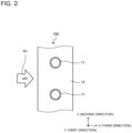
- Fig. 2 is a partial sectional side view illustrating only essential components of the heat exchanger 100 of Fig. 1 .
- Fig. 2 illustrates a section taken at a position in the Y direction.
- Fig. 2 illustrates the main surface of the fin 12 and cross-sections of the heat transfer tubes 11.
- Each of the heat transfer tubes 11 is, for example, a cylindrical tube or a flat tube.
- Figs. 1 and 2 illustrate the heat transfer tubes 11 being cylindrical tubes.
- the heat exchanger 100 exchanges heat between the air flowing along the main surfaces of the fins 12 and the refrigerant flowing inside the heat transfer tubes 11.
- the heat exchanger 100 is disposed such that the air flows in the X direction.
- the Z direction orthogonal to the X direction is, for example, a vertical direction.
- the Z direction will be referred to as a column direction of the heat transfer tubes 11, and the Y direction will be referred to as a row direction of the heat transfer tubes 11.
- the heat transfer tubes 11 are arranged in one column by twelve rows.
- the number of columns and the number of rows of the heat transfer tubes 11 are not limited to those examples.
- the heat transfer tubes 11 may be arranged in two columns, as illustrated in a modification of Fig. 3.
- Fig. 3 is a perspective view illustrating the modification of the heat exchanger 100 of Fig. 1 .
- the heat transfer tubes 11 in the first column are offset by 1/2 of the tube pitch from the heat transfer tubes 11 in the second column in the Z direction, as illustrated in Fig. 21 , which will be described later.
- the fin 12 for the first column is separate from the fin 12 for the second column in Fig. 21 , the fins 12 may be used without being divided, as illustrated in Fig. 3 .
- the number of rows in the first column differs from the number of rows in the second column. Specifically, the first column has 12 rows, and the second column has 10 rows in the modification of Fig. 3 .
- the numbers of rows of the heat transfer tubes 11 are not limited to those examples, and may be determined to be any values.
- the ends of the heat transfer tubes 11 that are adjacent in the Z direction are also connected by the U-shaped tube 11a.
- the multiple heat transfer tubes 11 are combined into an assembly, through which the refrigerant sequentially flows.
- the heat transfer tubes 11 also do not necessarily need to be combined in a single assembly, as in the example of Fig. 1 .
- Figs. 1 and 3 illustrates the heat transfer tubes 11 having the longitudinal direction in the Y direction.
- the Y direction is, for example, a horizontal direction.
- the longitudinal direction is not limited to this example.
- the longitudinal direction of the heat transfer tubes 11 may be in the vertical direction.
- the longitudinal direction of the fins 12 is in the horizontal direction.
- Fig. 4 is a refrigerant circuit diagram illustrating an exemplary configuration of the refrigeration cycle apparatus 1 in Embodiment 1. As illustrated in Fig. 4 , the refrigeration cycle apparatus 1 includes a heat source side unit 2 and a load side unit 3.
- the heat source side unit 2 and the load side unit 3 are connected to each other by a refrigerant pipe 8, as illustrated in Fig. 4 .
- the heat exchanger 100 can be used in the heat source side unit 2 and the load side unit 3.
- the heat exchanger 100 disposed in the heat source side unit 2 will be referred to as a heat exchanger 100A
- the heat exchanger 100 disposed in the load side unit 3 will be referred to as a heat exchanger 100B.
- the load side unit 3 includes the heat exchanger 100B, an air-sending device 7B, a controller 9B, and a part of the refrigerant pipe 8.
- the air-sending device 7B sends air to the heat exchanger 100B.
- the heat exchanger 100B exchanges heat between the air and the refrigerant flowing through the heat transfer tubes 11.
- the heat exchanger 100B operates as a condenser in a case where the refrigeration cycle apparatus 1 causes the load side unit 3 to perform heating, and operates as an evaporator in a case where the refrigeration cycle apparatus 1 causes the load side unit 3 to perform cooling.
- the air-sending device 7B is, for example, a propeller fan.
- the air-sending device 7B includes a fan motor 7a and a fan 7b.
- the fan 7b is rotated by the fan motor 7a, serving as a power source.
- the controller 9B controls a rotation speed of the air-sending device 7B.
- the heat source side unit 2 includes the heat exchanger 100A, a controller 9A, a compressor 4, a flow switching device 5, an expansion valve 6, an air-sending device 7A, and a part of the refrigerant pipe 8.
- the heat source side unit 2 may further include another component, such as an accumulator.
- the heat exchanger 100A exchanges heat between air and the refrigerant flowing through the heat transfer tubes 11.
- the heat exchanger 100A operates as an evaporator in the case where the refrigeration cycle apparatus 1 causes the load side unit 3 to perform heating, and operates as a condenser in the case where the refrigeration cycle apparatus 1 causes the load side unit 3 to perform cooling.
- the air-sending device 7A sends air to the heat exchanger 100A.
- the air-sending device 7A is, for example, a propeller fan.
- the air-sending device 7A includes the fan motor 7a and the fan 7b.
- the controller 9A controls the rotation speed of the air-sending device 7A.
- the compressor 4 sucks low-pressure gas refrigerant, compresses the refrigerant into high-pressure gas refrigerant, and discharges the refrigerant.
- the compressor 4 is, for example, an inverter compressor.
- the inverter compressor can change the amount of refrigerant to be sent per unit time under the control of, for example, an inverter circuit.
- the inverter circuit is incorporated in, for example, the controller 9A.
- the flow switching device 5 is a valve to switch between refrigerant flow directions in the refrigerant pipe 8.
- the flow switching device 5 is, for example, a four-way valve.
- the flow switching device 5 switches between a refrigerant flow direction for a cooling operation of the refrigeration cycle apparatus 1 and a refrigerant flow direction for a heating operation of the refrigeration cycle apparatus 1 under the control of the controller 9A.
- the flow switching device 5 enters a state represented by solid lines in Fig. 4 .
- the refrigerant discharged from the compressor 4 enters the heat exchanger 100A located in the heat source side unit 2.
- the flow switching device 5 enters a state represented by broken lines in Fig. 4 .
- the refrigerant discharged from the compressor 4 enters the heat exchanger 100B located in the load side unit 3.
- the expansion valve 6 is configured to throttle to reduce the pressure of incoming liquid refrigerant so that the refrigerant liquified in the condenser can be easily evaporated in the evaporator, and causes the refrigerant to flow out of the valve.
- the expansion valve 6 regulates the flow rate of refrigerant to maintain an appropriate refrigerant flow rate depending on a load on the evaporator.
- the expansion valve 6 is, for example, an electronic expansion valve.
- the controller 9A controls the opening degree of the expansion valve 6. As illustrated in Fig. 4 , the expansion valve 6 is connected between the heat exchanger 100A and the heat exchanger 100B by the refrigerant pipe 8.
- the refrigerant pipe 8 connects the compressor 4, the flow switching device 5, the heat exchanger 100A, the expansion valve 6, and the heat exchanger 100B, thus forming a refrigerant circuit.
- the refrigerant pipe 8 is coupled to the heat transfer tubes 11 of the heat exchanger 100A and the heat transfer tubes 11 of the heat exchanger 100B.
- Fig. 5 is a partial sectional side view of the heat exchanger 100 of Fig. 1 .
- Fig. 5 illustrates the main surface of the fin 12.
- Fig. 5 further illustrates the cross-sections of the heat transfer tubes 11.
- the cross-sections of the heat transfer tubes 11 in Fig. 5 are parallel to the main surfaces of the fin 12.
- the heat transfer tubes 11 are aligned in one column in the Z direction.
- the fin 12 has a front edge 12a and a rear edge 12b. Since the air flows in a direction represented by the arrow R1 in Fig. 5 , the front edge 12a is located upwind of the rear edge 12b.
- the heat transfer tubes 11 are received in through-holes 12c arranged in the fin 12.
- the heat transfer tubes 11 have an outside diameter, which matches an inside diameter of the through-holes 12c. Therefore, the heat transfer tubes 11 are in tight contact with inner walls of the through-holes 12c.
- the main surface of the fin 12 defines a fin base surface 121, which is flat.
- the fin base surface 121 has fin projections 122.
- Each of the fin projections 122 projects from the fin base surface 121, which is one of the main surfaces of the fin 12, in the Y direction.
- the fin projection 122 is located between two adjacent heat transfer tubes 11 of the multiple heat transfer tubes 11.
- the fin projection 122 has a rectangular shape in front view, as illustrated in Fig. 5 .
- the term "front view” refers to a view of the main surface, on which the fin projection 122 is provided, of the fin 12 when viewed in the Y direction, as illustrated in Fig. 5 .
- the fin projection 122 has an upper end 122u, a lower end 122d, and two side ends 122s.
- the upper end 122u, the lower end 122d, and the two side ends 122s extend linearly.
- the upper end 122u and the lower end 122d serve as long sides of a rectangle and are opposite each other.
- the two side ends 122s serve as short sides of the rectangle and are opposite each other.
- the upper end 122u and the lower end 122d extend in the X direction.
- the two side ends 122s extend in the Z direction.
- the fin projection 122 includes an uprise portion 122a and a main part 122b.
- the uprise portion 122a has a rectangular frame shape in front view.
- the main part 122b has a rectangular shape in front view.
- the main part 122b is located inside the uprise portion 122a.
- the uprise portion 122a surrounds the main part 122b.
- the area of the main part 122b is larger than that of the uprise portion 122a.
- the middle of the uprise portion 122a coincides with that of the main part 122b.
- the middle of the uprise portion 122a is the intersection of diagonals joining opposite corners of an outside shape of the uprise portion 122a.
- the middle of the main part 122b is the intersection of diagonals joining opposite corners of an outside shape of the main part 122b.
- the middle of the main part 122b and that of the uprise portion 122a coincide with the middle of the fin 12 in the X direction.
- the main part 122b has a quadrilateral pyramidal shape having a rectangular base.
- the uprise portion 122a has a truncated quadrilateral pyramidal shape having a rectangular base. Therefore, the fin projection 122 includes the uprise portion 122a, which is truncated quadrilateral pyramidal in shape, and the main part 122b, which is quadrilateral pyramidal in shape, located on the top of the uprise portion 122a.
- Fig. 6 is a cross-sectional view taken along line A-A in Fig. 5 .
- the uprise portion 122a is located between the fin base surface 121 and the main part 122b.
- the uprise portion 122a connects between the fin base surface 121 and the main part 122b.
- the surface of the uprise portion 122a and the fin base surface 121 form an angle ⁇ a.
- the surface of the main part 122b and the fin base surface 121 form an angle ⁇ b.
- a relationship between the angle ⁇ a and the angle ⁇ b ⁇ a > ⁇ b is established.
- the angle of inclination of the main part 122b is smaller than that of the uprise portion 122a.
- the air collides with the side end 122s of each fin projection 122 and thus splits into upward and downward streams.
- the upward and downward air streams flow toward windward sides of the heat transfer tubes 11 located above and below the fin projection 122.
- some of the air flows through a space between each of the heat transfer tubes 11 and the fin projection 122.
- the air flows along the heat transfer tube 11 to a leeward side of the heat transfer tube 11.
- a dead zone does not occur on the windward side and the leeward side of the heat transfer tube 11.
- the air flows over the fin projection 122 from the windward side to the leeward side, as illustrated in Fig. 8 , which will be described later.
- FIG. 7 is a diagram illustrating a cross-section of a projection 500 described in Patent Literature 1.
- Fig. 8 is a diagram illustrating the flow of air with the cross-section taken along line A-A of Fig. 6 .
- arrows each represent the flow of air.
- each of the fins described in Patent Literature 1 includes the projections 500 each having a right square pyramidal shape.
- Each projection 500 and the main surface of the fin form a large angle, which makes it difficult for the air flowing from the windward side to flow along the surface of the projection 500 on the leeward side.
- the air flows at a distance from the surface of the projection 500 on the leeward side, as represented by the arrow in Fig. 7 .
- a dead zone 501 occurs on the leeward side of the projection 500, as illustrated in Fig. 7 .
- the air fails to exchange heat with the refrigerant efficiently.
- the angle of inclination of the main part 122b is smaller than that of the uprise portion 122a. This allows the air to flow easily along the fin projection 122, as illustrated in Fig. 8 .
- the main part 122b which slopes gently, causes the air to flow gently. The air flows along the surface of the main part 122b.
- the air flows along the surface of the main part 122b and the surface of the uprise portion 122a on the leeward side, as represented by the arrows in Fig. 8 .
- the dead zones 201 are significantly reduced in size as compared with the dead zone 501 in Fig. 7 .
- Embodiment 1 can reduce the dead zones 201. This results in an increase in area of a region of the surface of the fin 12 that is available for heat exchange. This leads to improved efficiency of heat transfer on the surface of the fin 12.
- Fig. 9 is a partial sectional side view illustrating the fin 12 of the heat exchanger 100 according to Modification 1 of Embodiment 1.
- Fig. 9 illustrates the surface of the fin 12 and cross-sections of the heat transfer tubes 11 that are parallel to the main surfaces of the fin 12.
- Fig. 10 is a cross-sectional view taken along line A-A in Fig. 9 .
- the fin projection 122 in Modification 1 illustrated in Figs. 9 and 10 also includes the uprise portion 122a and the main part 122b, as in Embodiment 1.
- the angles ⁇ a and ⁇ b in Modification 1 are defined in the same manner as in Embodiment 1 illustrated in Fig. 6 .
- the uprise portion 122a and the fin base surface 121 form the angle ⁇ a
- the main part 122b and the fin base surface 121 form the angle ⁇ b.
- Fig. 11 is a diagram illustrating the flow of air with the cross-section taken along line A-A of Fig. 10 .
- the angle of inclination of the main part 122b is smaller than that of the uprise portion 122a in the fin projection 122 in Modification 1. This allows air to flow easily along the fin projection 122, as illustrated in Fig. 11 .
- the main part 122b is flat in Modification 1. This allows air to flow more easily along the fin projection.
- the dead zone 201 on the leeward side of the fin projection 122 is reduced, as in Embodiment 1.
- the dead zone 201 is small in Modification 1. This results in an increase in area of a region of the surface of the fin 12 that is available for heat exchange. This leads to improved efficiency of heat transfer on the surface of the fin 12, as in Embodiment 1.
- Fig. 12 is a partial sectional side view illustrating the fin 12 of the heat exchanger 100 according to Modification 2 of Embodiment 1.
- Fig. 12 illustrates the surface of the fin 12 and cross-sections of the heat transfer tubes 11 that are parallel to the main surfaces of the fin 12.
- Fig. 13 is a cross-sectional view taken along line A-A in Fig. 12 .
- the fin projection 122 in Modification 2 illustrated in Figs. 12 and 13 also includes the uprise portion 122a and the main part 122b, as in Embodiment 1.
- the main part 122b has a vertex located closer to the front edge 12a than the middle of the fin 12 in the X direction. Furthermore, as illustrated in Figs. 12 and 13 , the main part 122b includes a windward main-part element 122b-1 and a leeward main-part element 122b-2. The area of the windward main-part element 122b-1 is smaller than that of the leeward main-part element 122b-2.
- the windward main-part element 122b-1 is a portion of the main part 122b that is located on the windward side in the X direction.
- the windward main-part element 122b-1 has a triangular shape in front view.
- the leeward main-part element 122b-2 is a portion of the main part 122b that is located on the leeward side in the X direction.
- the leeward main-part element 122b-2 has a triangular shape in front view.
- the windward main-part element 122b-1 and the fin base surface 121 form an angle ⁇ b1.
- the leeward main-part element 122b-2 and the fin base surface 121 form an angle ⁇ b2.
- the uprise portion 122a includes a windward uprise-portion element 122a-1 and a leeward uprise-portion element 122a-2.
- the area of the windward uprise-portion element 122a-1 is smaller than that of the leeward uprise-portion element 122a-2.
- the windward uprise-portion element 122a-1 is a part of the uprise portion 122a that is located on the windward side.
- the windward uprise-portion element 122a-1 has a trapezoidal shape in front view.
- the leeward uprise-portion element 122a-2 is a part of the uprise portion 122a that is located on the leeward side.
- the leeward uprise-portion element 122a-2 has a trapezoidal shape in front view.
- the windward uprise-portion element 122a-1 and the fin base surface 121 form an angle ⁇ a1.
- the leeward uprise-portion element 122a-2 and the fin base surface 121 form an angle ⁇ a2.
- the angle ⁇ a1 and the angle ⁇ b1 have a relationship of ⁇ a1 > ⁇ b1. Furthermore, the angle ⁇ a2 and the angle ⁇ b2 in Modification 2 have a relationship of ⁇ a2 > ⁇ b2. In other words, the angle of inclination of the main part 122b is smaller than that of the uprise portion 122a in Modification 2. For a relationship between the angle ⁇ a2 and the angle ⁇ b1, it is desirable that ⁇ a2 > ⁇ b1.
- the angle ⁇ a2 and the angle ⁇ b1 may be equal to each other or may satisfy ⁇ a2 ⁇ ⁇ b1.
- Fig. 14 is a diagram illustrating the flow of air with the cross-section taken along line A-A of Fig. 13 .
- the fin projection 122 in Modification 2 is shaped such that the angle of inclination of the main part 122b is smaller than that of the uprise portion 122a.
- the angle of inclination of the leeward element is smaller than that of the windward element. This allows air to flow easily along the fin projection 122, as illustrated in Fig. 14 .
- the dead zones 201 on the leeward side of the fin projection 122 are reduced, as in Embodiment 1.
- the dead zones 201 are small in Modification 2. This results in an increase in area of a region of the surface of the fin 12 that is available for heat exchange. This leads to improved efficiency of heat transfer on the surface of the fin 12, as in Embodiment 1.
- the relationship between the angle ⁇ a1 formed by the windward uprise-portion element 122a-1 and the fin base surface 121 and the angle ⁇ a2 formed by the leeward uprise-portion element 122a-2 and the fin base surface 121 is ⁇ a1 > ⁇ a2. This allows the dead zones 201 on or near the leeward uprise-portion element 122a-2 to be further reduced, as compared with Embodiment 1. This leads to further improved efficiency of heat transfer on the surface of the fin 12.
- Fig. 15 is a cross-sectional view illustrating the fin 12 of the heat exchanger 100 according to Modification 3 of Embodiment 1.
- the relationship between the angle ⁇ a and the angle ⁇ b on each of the windward side and the leeward side is ⁇ a > ⁇ b, as illustrated in Fig. 6 .
- Modification 3 differs from Embodiment 1 in this respect.
- the relationship between the angle ⁇ a and the angle ⁇ b in Modification 3 is also ⁇ a > ⁇ b, as in Embodiment 1.
- the fin projection 122 in Modification 3 also includes the uprise portion 122a and the main part 122b, as in Modification 2.
- the uprise portion 122a includes the windward uprise-portion element 122a-1 and the leeward uprise-portion element 122a-2.
- the windward uprise-portion element 122a-1 and the fin base surface 121 form the angle ⁇ a1.
- the main part 122b includes the windward main-part element 122b-1 and the leeward main-part element 122b-2.
- the windward main-part element 122b-1 and the fin base surface 121 form the angle ⁇ b1.
- the rest of the configuration of the heat exchanger 100 is the same as that in Embodiment 1, and a description thereof is omitted herein.
- Modification 3 also offers the same advantages as those of Embodiment 1 as well as the same advantages as those of Modification 2.
- a heat exchanger 100 according to Embodiment 2 and a refrigeration cycle apparatus 1 in Embodiment 2 will be described below.
- a basic configuration of the heat exchanger 100 according to Embodiment 2 is the same as that of the heat exchanger 100 according to Embodiment 1, and a description thereof is omitted herein.
- a basic configuration of the refrigeration cycle apparatus 1 in Embodiment 2 is the same as that of the refrigeration cycle apparatus 1 in Embodiment 1, and a description thereof is omitted herein.
- Fig. 17 is a partial sectional side view of the heat exchanger 100 of Fig. 1 .
- Fig. 17 illustrates a main surface of a fin 12 and cross-sections of heat transfer tubes 11.
- the cross-sections of the heat transfer tubes 11 in Fig. 17 are parallel to the main surfaces of the fin 12.
- the heat transfer tubes 11 are aligned in one column in the column direction parallel to the longitudinal direction of the fin 12.
- the fin 12 has a front edge 12a and a rear edge 12b. Since air flows in the direction of the arrow R1, the front edge 12a is located upwind of the rear edge 12b.
- the main surface of the fin 12 defines a fin base surface 121, which is flat.
- the fin base surface 121 has fin projections 122A.
- Each of the fin projections 122A projects from one of the main surfaces of the fin 12.
- the fin projection 122A is located between the heat transfer tubes 11 that are adjacent.
- the fin projection 122A has a hexagonal shape in front view, as illustrated in Fig. 17 .
- the fin projection 122A has an upper end 122u, a lower end 122d, and two V-shaped side ends 122s.
- the upper end 122u and the lower end 122d are opposite each other.
- the upper end 122u and the lower end 122d extend linearly.
- the upper end 122u and the lower end 122d extend in the X direction.
- the V-shaped side ends 122s are opposite each other. In other words, the side ends 122s each have a tapered shape.
- the side end 122s on the windward side is tapered toward the front edge 12a of the fin 12.
- the side end 122s on the leeward side is tapered toward the rear edge 12b of the fin 12.
- the side end 122s on the windward side includes a first angled end part 122s-1 and a second angled end part 122s-2.
- the first angled end part 122s-1 and the second angled end part 122s-2 are arranged in a V-shape.
- the first angled end part 122s-1 is inclined from the X direction toward the Z direction.
- the second angled end part 122s-2 is inclined from the X direction toward a negative Z direction.
- the angle of inclination ⁇ of these end parts ranges from approximately 40 to approximately 60 degrees, for example.
- the X direction is referred to as a third direction
- the Z direction and the negative Z direction are collectively referred to as a second direction
- the first angled end part 122s-1 and the second angled end part 122s-2 are each inclined from the third direction toward the second direction.
- the side end 122s on the leeward side includes a third angled end part 122s-3 and a fourth angled end part 122s-4.
- the third angled end part 122s-3 and the fourth angled end part 122s-4 are arranged in a V-shape.
- the third angled end part 122s-3 is inclined from a negative X direction toward the Z direction.
- the fourth angled end part 122s-4 is inclined from the negative X direction toward the negative Z direction.
- the angle, ⁇ , of inclination of these end parts ranges from approximately 40 to approximately 60 degrees, for example.
- the X direction and the negative X direction are collectively referred to as the third direction
- the Z direction and the negative Z direction are collectively referred to as the second direction
- the third angled end part 122s-3 and the fourth angled end part 122s-4 are each inclined from the third direction toward the second direction.
- the dimension of the fin projection 122A in the Z direction increases from an upstream end of the fin projection 122A to a middle portion of the fin projection 122A in the X direction, in which the air flows, remains unchanged in the middle portion, and decreases from the middle portion to a downstream end of the fin projection 122A.
- the fin projection 122A includes an uprise portion 122a and a main part 122b.
- the uprise portion 122a has a hexagonal frame shape in front view.
- the main part 122b has a hexagonal shape in front view.
- the main part 122b is located inside the uprise portion 122a.
- the uprise portion 122a surrounds the main part 122b.
- the area of the main part 122b is larger than that of the uprise portion 122a.
- the middle of the uprise portion 122a coincides with that of the main part 122b.
- the middle of the uprise portion 122a is the intersection of diagonals joining opposite corners of an outside shape of the uprise portion 122a.
- the middle of the main part 122b is the intersection of diagonals joining opposite corners of an outside shape of the main part 122b.
- the main part 122b has a hexagonal pyramidal shape having a hexagonal base.
- the uprise portion 122a has a truncated hexagonal pyramidal shape having a hexagonal base. Therefore, the fin projection 122A includes the uprise portion 122a, which is truncated hexagonal pyramidal in shape, and the main part 122b, which is hexagonal pyramidal in shape, located on the top of the uprise portion 122a.
- the uprise portion 122a has two windward slopes 122g, two leeward slopes 122h, an upper slope 122e, and a lower slope 122f.
- the windward slopes 122g have the first angled end part 122s-1 and the second angled end part 122s-2, each of which has an angle of inclination from the third direction toward the second direction.
- the leeward slopes 122h have the third angled end part 122s-3 and the fourth angled end part 122s-4, which are inclined from the third direction toward the second direction.
- Fig. 18 is a cross-sectional view taken along line A-A in Fig. 17 .
- the uprise portion 122a is located between the fin base surface 121 and the main part 122b.
- the main part 122b is surrounded by the uprise portion 122a.
- the uprise portion 122a forms an angle ⁇ a against the fin base surface 121.
- the main part 122b forms an angle ⁇ b against the fin base surface 121. In this state, a relationship between the angle ⁇ a and the angle ⁇ b ⁇ a > ⁇ b is established.
- the windward slope 122g has a downstream end P.
- the downstream end P is located upstream of the center of the heat transfer tube 11, as represented by an arrow Q.
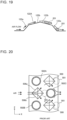
- Fig. 19 is a diagram illustrating the flow of air with the cross-section taken along line A-A of Fig. 18 .
- the fin projection 122A in Embodiment 2 is shaped such that the angle of inclination of the main part 122b is smaller than that of the uprise portion 122a. This allows air to flow easily along the fin projection 122A, as illustrated in Fig. 19 .
- dead zones 201 on the leeward side of the fin projection 122A are significantly reduced, as compared with the dead zone 501 in Patent Literature 1 illustrated in Fig. 11 .
- the dead zones 201 are small in Embodiment 2. This results in an increase in area of a region of the surface of the fin 12 that is available for heat exchange. This leads to improved efficiency of heat transfer on the surface of the fin 12.
- Fig. 20 is a front view illustrating the projections 500 described in Patent Literature 1.
- Fig. 20 illustrates heat transfer tubes 502.
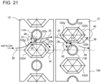
- Fig. 21 is a front view illustrating the fin projections 122A in Embodiment 2.
- Fig. 21 illustrates the heat transfer tubes 11 arranged in two columns for comparison with Fig. 20 .
- Fig. 21 illustrates the fin projections 122A in Embodiment 2 included in the heat exchanger 100 of Fig. 3 .
- each fin 12 is shared by the heat transfer tubes 11 arranged in two columns in the example of Fig. 3 , the arrangement is not limited to the example.
- the fin 12 may be provided for each column, as illustrated in Fig. 21 . Specifically, each of the fins 12 in Fig. 3 is divided into two parts for two columns in Fig. 21 .
- Embodiment 2 causes the following actions (1) and (2) of air.
- the action (2) will now be described.
- the air flowing in the direction of the arrow 33 passes downwind of the heat transfer tube 11A and flows toward the fin projection 122A in the second column.
- no dead zone occurs downwind of the heat transfer tube 11A.
- the air is guided to an area 42 by the windward slope 122g of the fin projection 122A in the second column, as represented by an arrow 35.
- the air collides with a heat transfer tube 11B and splits into two streams in the area 42.
- One of the air streams is guided to a windward side of the heat transfer tube 11B in the second column, as represented by an arrow 36.
- the other air stream flows along the lower slope 122f of the fin projection 122, as represented by an arrow 37.
- Fig. 21 illustrates the example in which the heat transfer tubes 11 are arranged in two columns
- the same advantages as those in this example are also obtained in a case where the heat transfer tubes 11 are aligned in one column.
- the above-described action (1) occurs above the fin projection 122A
- the above-described action (2) occurs below the fin projection 122A. Therefore, the same advantages are obtained in the case where the heat transfer tubes 11 are aligned in one column, as well as in the case where the heat transfer tubes 11 are arranged in multiple columns.
- the uprise portion 122a in Embodiment 2 has the leeward slopes 122h on the leeward side.
- the leeward slopes 122h have the third angled end part 122s-3 and the fourth angled end part 122s-4 inclined from the third direction toward the second direction. This facilitates flow of air in a direction from the heat transfer tube 11 to the leeward side of the fin projection 122A, as represented by the arrows 34 and 38 in Fig. 21 .
- the dead zones 201 on the leeward side of the fin projection 122A are reduced, as illustrated in Fig. 19 . This leads to improved heat transfer efficiency of the fin 12.
- the uprise portion 122a in Embodiment 2 has the multiple windward slopes 122g on the windward side.
- the windward slopes 122g have the first angled end part 122s-1 and the second angled end part 122s-2 inclined from the third direction toward the second direction.
- the downstream end P of each windward slope 122g is located upstream of the center of each heat transfer tube 11. This facilitates flow of air in a direction from the fin projection 122A to the windward side of the heat transfer tube 11, as represented by the arrows 31 and 36 in Fig. 21 .
- the windward side of the heat transfer tube 11 is included in an area whose temperature is close to a heat source temperature. In Embodiment 2, the flux of air passing through the area whose temperature is close to the heat source temperature is increased, thus improving heat flux.
- Embodiment 2 also offers the same advantages as those of Embodiment 1.
- the angle ⁇ a1 on the windward side and the angle ⁇ a2 on the leeward side of the uprise portion 122a in Embodiment 2 may differ from each other, as in Modification 2 of Embodiment 1 illustrated in Figs. 12 and 13 .
- the angle ⁇ b1 on the windward side and the angle ⁇ b2 on the leeward side of the main part 122b may differ from each other. In this case, the same advantages as those of Modification 2 of Embodiment 1 can be obtained.
- the angle ⁇ a1 of the uprise portion 122a and the angle ⁇ b1 of the main part 122b on the windward side in Embodiment 2 may be equal to each other, as in Modification 3 of Embodiment 1 illustrated in Figs. 15 and 16 . In this case, the same advantages as those of Modification 3 of Embodiment 1 can be obtained.
- a heat exchanger 100 according to Embodiment 3 and a refrigeration cycle apparatus 1 in Embodiment 3 will be described below.
- a basic configuration of the heat exchanger 100 according to Embodiment 3 is the same as that of the heat exchanger 100 according to Embodiment 1, and a description thereof is omitted herein.
- a basic configuration of the refrigeration cycle apparatus 1 in Embodiment 3 is the same as that of the refrigeration cycle apparatus 1 in Embodiment 1, and a description thereof is omitted herein.
- Fig. 22 is a partial sectional side view of the heat exchanger 100 of Fig. 1 .
- Fig. 22 illustrates a surface of a fin 12.
- Fig. 22 further illustrates cross-sections of heat transfer tubes 11.
- the cross-sections of the heat transfer tubes 11 in Fig. 22 are parallel to main surfaces of the fin 12.
- the heat transfer tubes 11 are aligned in one column in the Z direction.
- the fin 12 has a front edge 12a and a rear edge 12b. Since air flows in the direction of the arrow R1 in Fig. 5 , the front edge 12a is located upwind of the rear edge 12b.
- the main surface of the fin 12 defines a fin base surface 121, which is flat.
- the fin base surface 121 has a fin projection 122B.
- the fin projection 122B projects from one of the main surfaces of the fin 12.
- the fin projection 122B is located between the heat transfer tubes 11 that are adjacent. As illustrated in Fig. 22 , the fin projection 122B has a hexagonal shape in front view.
- the fin projection 122B has an upper end 122u, a lower end 122d, and two V-shaped side ends 122s.
- the upper end 122u and the lower end 122d are opposite each other.
- the upper end 122u and the lower end 122d extend in the X direction.
- the fin projection 122B includes an uprise portion 122a and a main part 122b.
- the main part 122b is flat, as in Modification 1 of Embodiment 2.
- the above-described details of the structure are the same as those in Modification 1 of Embodiment 2.
- the fin projection 122B includes three separate blocks. Hereinafter, these blocks will be referred to as fin projections 122B-1, 122B-2, and 122B-3. Therefore, the fin projection 122B includes the fin projections 122B-1, 122B-2, and 122B-3.
- the multiple fin projections 122B-1, 122B-2, and 122B-3 are arranged in the Z direction between the heat transfer tubes 11 that are adjacent in the Z direction.
- the fin projection 122B-1 has a trapezoidal shape in front view.
- An upper base of the fin projection 122B-1, which is a trapezoid, is shorter than a lower base thereof.
- the fin projection 122B-2 is located below the fin projection 122B-1.
- the fin projection 122B-2 has a hexagonal shape in front view.
- the fin projection 122B-3 is located below the fin projection 122B-2.
- the fin projection 122B-3 has a trapezoidal shape in front view.
- An upper base of the fin projection 122B-3 which is a trapezoid, is longer than a lower base thereof.
- the fin projections 122B-1, 122B-2, and 122B-3 each include the uprise portion 122a and the main part 122b, which is flat.
- the fin projection 122B-1 and the fin projection 122B-2 have an air groove 130 in between.
- the fin projection 122B-2 and the fin projection 122B-3 have an air groove 130 in between.
- These air grooves 130 extend in the X direction.
- Embodiment 3 provides the grooves each extending in the X direction and each located between two fin projections of the fin projections 122B-1, 122B-2, and 122B-3 that are adjacent in the Z direction.
- Fig. 23 is a sectional view taken along line B-B in Fig. 22 . As illustrated in Fig. 23 , the air grooves 130 each have a bottom 130a located at the same level as the fin base surface 121 in the Y direction.
- the rest of the configuration of the heat exchanger 100 is the same as those in Embodiment 1 or Embodiment 2, and a description thereof is omitted herein.
- the fin in Embodiment 3 includes the fin projection 122B having a hexagonal shape in front view, as in Embodiment 2.
- Embodiment 3 therefore offers the same advantages as those of Embodiment 2.
- the fin projection 122B includes separate blocks.
- the multiple fin projections 122B-1, 122B-2, and 122B-3 are arranged in the Z direction between the heat transfer tubes 11 that are adjacent in the Z direction.
- Each air groove 130 extending in the X direction is provided between two adjacent fin projections of the fin projections 122B-1, 122B-2, and 122B-3.
- the air groove 130 extends in the same direction as the direction in which the air flows.
- Fig. 24 is a cross-sectional view taken along line A-A in Fig. 22 . As represented by a broken-line arrow in Fig. 24 , the air flows through the air groove 130. This further increases the area of heat transfer, as compared with Embodiments 1 and 2. This leads to further improved heat transfer efficiency of the fin 12.
- Fig. 25 is a front view illustrating the fin projection 122B in Modification 1 of Embodiment 3.
- Fig. 26 is a sectional view taken along line B-B in Fig. 25 .
- the structure of the fin projection 122B in Modification 1 of Embodiment 3 is basically the same as that in Embodiment 3.
- the bottom 130a of each air groove 130 is located at a level different from the fin base surface 121 in the Y direction. Modification 1 differs from Embodiment 3 only in this respect.
- the level of the bottom 130a of each air groove 130 in the Y direction is higher than the fin base surface 121.
- the structure is not limited to this example.
- the level of the bottom 130a of the air groove 130 in the Y direction may be lower than the fin base surface 121.
- Modification 1 also offers the same advantages as those of Embodiment 3.
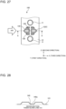
- Fig. 27 is a front view illustrating a fin projection 122C in Modification 2 of Embodiment 3.
- Fig. 28 is a cross-sectional view taken along line A-A in Fig. 27 .
- the structure of the fin projection 122C in Modification 2 of Embodiment 3 is basically the same as that of the fin projection 122B in Embodiment 3.
- a drain groove 140 extending in the Z direction is added to and located in a middle part of the fin projection 122B in Embodiment 3.
- Modification 2 differs from Embodiment 3 only in this respect.
- the drain groove 140 has a bottom 140a located at the same level as the fin base surface 121 in the Y direction.
- the structure is not limited to this example.
- the level of the bottom 140a of the drain groove 140 in the Y direction may be higher than or lower than the fin base surface 121.
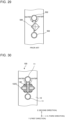
- Fig. 29 is a front view illustrating the projection 500 of the fin in Patent Literature 1.
- Fig. 30 is a diagram illustrating the flow of water with the front view of Fig. 27 , which illustrates Modification 2 of Embodiment 3.
- the temperature of the refrigerant flowing through the heat transfer tubes 11 may fall depending on an operation state of the refrigeration cycle apparatus 1, and condensate water, namely, condensation may occur on the heat transfer tubes 11.
- condensate water flows around the projection 500, as represented by arrows in Fig. 29 . This results in a longer path through which the condensate water is drained.
- Modification 2 of Embodiment 3 provides the drain groove 140 extending in the Z direction and located in the middle part of the fin projection 122C.
- Such a configuration causes condensate water to flow downward through the drain groove 140, as represented by arrows in Fig. 30 .
- the configuration facilitates flow of condensate water and reduces the length of a path through which the condensate water is drained.
- the condensate water can be efficiently drained out of the heat exchanger 100.
- the surface of the fin 12 in Modification 2 of Embodiment 3 has the fin projection 122C having a hexagonal base, as in Embodiment 3.
- Modification 2 of Embodiment 3 therefore offers the same advantages as those of Embodiment 3.
- the fin projection 122C has the drain groove 140.
- this facilitates drainage of condensate water.
- the fin projection 122B includes the three separate blocks arranged in the Z direction, and the two air grooves 130 extending in the X direction are provided such that each air groove is located between two adjacent blocks.
- the number of blocks and the number of air grooves 130 are not limited to those in the above example.
- the fin projection 122B may include n (n is a positive integer) separate blocks arranged in the Z direction, and (n-1) air grooves 130 extending in the X direction may be provided between the blocks.
- the fin projection may have two or more drain grooves 140.
- the refrigeration cycle apparatus 1 of Fig. 4 can include the heat exchanger 100 described above in Embodiments 1 to 3 and Modifications of Embodiments 1 to 3.
- the dead zones 201 caused by the fin projections 122, 122A, 122B, or 122C of each fin 12 of the heat exchanger 100 can be reduced in size, thus increasing the area of heat transfer of the fin 12. This improves the heat transfer efficiency of the heat exchanger 100 and reduces or eliminates deterioration of ventilation, thus improving the performance of the heat exchanger 100. This leads to higher overall efficiency of the refrigeration cycle apparatus 1.
Landscapes
- Engineering & Computer Science (AREA)
- Physics & Mathematics (AREA)
- Thermal Sciences (AREA)
- Mechanical Engineering (AREA)
- General Engineering & Computer Science (AREA)
- Geometry (AREA)
- Heat-Exchange Devices With Radiators And Conduit Assemblies (AREA)
Applications Claiming Priority (1)
| Application Number | Priority Date | Filing Date | Title |
|---|---|---|---|
| PCT/JP2020/014479 WO2021199121A1 (ja) | 2020-03-30 | 2020-03-30 | 熱交換器および冷凍サイクル装置 |
Publications (3)
| Publication Number | Publication Date |
|---|---|
| EP4130634A1 EP4130634A1 (en) | 2023-02-08 |
| EP4130634A4 EP4130634A4 (en) | 2023-05-10 |
| EP4130634B1 true EP4130634B1 (en) | 2024-06-19 |
Family
ID=77929795
Family Applications (1)
| Application Number | Title | Priority Date | Filing Date |
|---|---|---|---|
| EP20928270.6A Active EP4130634B1 (en) | 2020-03-30 | 2020-03-30 | Heat exchanger and refrigeration cycle device |
Country Status (4)
| Country | Link |
|---|---|
| EP (1) | EP4130634B1 (https=) |
| JP (1) | JP7309041B2 (https=) |
| ES (1) | ES2987256T3 (https=) |
| WO (1) | WO2021199121A1 (https=) |
Families Citing this family (1)
| Publication number | Priority date | Publication date | Assignee | Title |
|---|---|---|---|---|
| KR20250081223A (ko) * | 2023-11-29 | 2025-06-05 | 엘지전자 주식회사 | 열교환기 |
Family Cites Families (17)
| Publication number | Priority date | Publication date | Assignee | Title |
|---|---|---|---|---|
| JPS5620715Y2 (https=) * | 1973-07-17 | 1981-05-15 | ||
| JPS5224301Y2 (https=) * | 1973-12-11 | 1977-06-02 | ||
| JPS5787979U (https=) * | 1980-11-13 | 1982-05-31 | ||
| JPS63294494A (ja) * | 1987-05-27 | 1988-12-01 | Nippon Denso Co Ltd | 熱交換器 |
| JPH10227589A (ja) * | 1996-12-12 | 1998-08-25 | Daikin Ind Ltd | ワッフル型クロスフィン熱交換器 |
| JP2001174181A (ja) * | 1999-10-06 | 2001-06-29 | Mitsubishi Heavy Ind Ltd | フィンアンドチューブ熱交換器及びこれを備えた空気調和機 |
| KR100543599B1 (ko) * | 2003-09-15 | 2006-01-20 | 엘지전자 주식회사 | 열교환기 |
| JP4687030B2 (ja) * | 2004-07-30 | 2011-05-25 | パナソニック株式会社 | 空気調和機 |
| WO2007108386A1 (ja) | 2006-03-23 | 2007-09-27 | Matsushita Electric Industrial Co., Ltd. | フィンチューブ型熱交換器、熱交換器用フィンおよびヒートポンプ装置 |
| JP4028591B2 (ja) * | 2006-04-21 | 2007-12-26 | 松下電器産業株式会社 | 伝熱フィンおよびフィンチューブ型熱交換器 |
| JP2008215670A (ja) * | 2007-03-01 | 2008-09-18 | Matsushita Electric Ind Co Ltd | 伝熱フィン、フィンチューブ型熱交換器および冷凍サイクル装置 |
| JP5072983B2 (ja) * | 2010-01-12 | 2012-11-14 | 三菱電機株式会社 | フィンチューブ型熱交換器およびこれを用いた空調装置 |
| WO2011096124A1 (ja) * | 2010-02-08 | 2011-08-11 | 住友軽金属工業株式会社 | フィン・アンド・チューブ式熱交換器 |
| KR101451056B1 (ko) * | 2011-01-21 | 2014-10-16 | 다이킨 고교 가부시키가이샤 | 열교환기 및 공기 조화기 |
| KR20120119469A (ko) * | 2011-04-21 | 2012-10-31 | 엘지전자 주식회사 | 열교환기 |
| JP6592930B2 (ja) * | 2015-03-26 | 2019-10-23 | 株式会社富士通ゼネラル | 熱交換器 |
| JP2015132468A (ja) * | 2015-04-22 | 2015-07-23 | 三菱電機株式会社 | 空気調和機の熱交換器 |
-
2020
- 2020-03-30 EP EP20928270.6A patent/EP4130634B1/en active Active
- 2020-03-30 WO PCT/JP2020/014479 patent/WO2021199121A1/ja not_active Ceased
- 2020-03-30 ES ES20928270T patent/ES2987256T3/es active Active
- 2020-03-30 JP JP2022512516A patent/JP7309041B2/ja active Active
Also Published As
| Publication number | Publication date |
|---|---|
| EP4130634A1 (en) | 2023-02-08 |
| JP7309041B2 (ja) | 2023-07-14 |
| ES2987256T3 (es) | 2024-11-14 |
| WO2021199121A1 (ja) | 2021-10-07 |
| EP4130634A4 (en) | 2023-05-10 |
| JPWO2021199121A1 (https=) | 2021-10-07 |
Similar Documents
| Publication | Publication Date | Title |
|---|---|---|
| EP3156752B1 (en) | Heat exchanger | |
| EP3561430A2 (en) | Heat exchanger | |
| WO2021234958A1 (ja) | 熱交換器、熱交換器を備えた室外機、および、室外機を備えた空気調和装置 | |
| US20200116365A1 (en) | Heat exchanger, refrigeration cycle device, and air-conditioning apparatus | |
| US20110120177A1 (en) | Heat exchanger for shedding water | |
| KR20140018199A (ko) | 열교환기 및 이를 탑재한 공기 조화기 | |
| EP3699538A1 (en) | Heat exchanger and refrigeration cycle device | |
| EP4130634B1 (en) | Heat exchanger and refrigeration cycle device | |
| US11384997B2 (en) | Heat exchanger, heat exchanger unit, and refrigeration cycle apparatus | |
| CN118829842A (zh) | 热交换器以及具备该热交换器的制冷循环装置 | |
| US11573056B2 (en) | Heat exchanger, heat exchanger unit, and refrigeration cycle apparatus | |
| JP2012052676A (ja) | 熱交換器及びそれを用いた空気調和機 | |
| US20250257949A1 (en) | Heat exchanger and air-conditioning apparatus | |
| KR102078275B1 (ko) | 공기조화기의 열교환기 | |
| JP7353483B2 (ja) | 熱交換器及び該熱交換器を備えた空気調和機 | |
| JP2011064338A (ja) | 空気調和機 | |
| JPWO2020021706A1 (ja) | 熱交換器、熱交換器ユニット、及び冷凍サイクル装置 | |
| WO2020121615A1 (ja) | 室内機および空気調和機 | |
| US20230147134A1 (en) | Heat exchanger and air-conditioning apparatus | |
| JP7756833B1 (ja) | 熱交換器及び空気調和装置 | |
| JPWO2019176061A1 (ja) | 熱交換器及び冷凍サイクル装置 | |
| JP7150157B2 (ja) | 熱交換器および冷凍サイクル装置 | |
| JP7675951B1 (ja) | 熱交換器及び空気調和装置 | |
| US20250044033A1 (en) | Heat exchanger and refrigeration cycle apparatus | |
| JP2008082619A (ja) | 熱交換器 |
Legal Events
| Date | Code | Title | Description |
|---|---|---|---|
| STAA | Information on the status of an ep patent application or granted ep patent |
Free format text: STATUS: THE INTERNATIONAL PUBLICATION HAS BEEN MADE |
|
| PUAI | Public reference made under article 153(3) epc to a published international application that has entered the european phase |
Free format text: ORIGINAL CODE: 0009012 |
|
| STAA | Information on the status of an ep patent application or granted ep patent |
Free format text: STATUS: REQUEST FOR EXAMINATION WAS MADE |
|
| 17P | Request for examination filed |
Effective date: 20220913 |
|
| AK | Designated contracting states |
Kind code of ref document: A1 Designated state(s): AL AT BE BG CH CY CZ DE DK EE ES FI FR GB GR HR HU IE IS IT LI LT LU LV MC MK MT NL NO PL PT RO RS SE SI SK SM TR |
|
| A4 | Supplementary search report drawn up and despatched |
Effective date: 20230412 |
|
| RIC1 | Information provided on ipc code assigned before grant |
Ipc: F28F 1/32 20060101AFI20230404BHEP |
|
| DAV | Request for validation of the european patent (deleted) | ||
| DAX | Request for extension of the european patent (deleted) | ||
| GRAP | Despatch of communication of intention to grant a patent |
Free format text: ORIGINAL CODE: EPIDOSNIGR1 |
|
| STAA | Information on the status of an ep patent application or granted ep patent |
Free format text: STATUS: GRANT OF PATENT IS INTENDED |
|
| INTG | Intention to grant announced |
Effective date: 20240209 |
|
| GRAS | Grant fee paid |
Free format text: ORIGINAL CODE: EPIDOSNIGR3 |
|
| GRAA | (expected) grant |
Free format text: ORIGINAL CODE: 0009210 |
|
| STAA | Information on the status of an ep patent application or granted ep patent |
Free format text: STATUS: THE PATENT HAS BEEN GRANTED |
|
| AK | Designated contracting states |
Kind code of ref document: B1 Designated state(s): AL AT BE BG CH CY CZ DE DK EE ES FI FR GB GR HR HU IE IS IT LI LT LU LV MC MK MT NL NO PL PT RO RS SE SI SK SM TR |
|
| REG | Reference to a national code |
Ref country code: GB Ref legal event code: FG4D |
|
| REG | Reference to a national code |
Ref country code: CH Ref legal event code: EP |
|
| REG | Reference to a national code |
Ref country code: DE Ref legal event code: R096 Ref document number: 602020032811 Country of ref document: DE |
|
| PG25 | Lapsed in a contracting state [announced via postgrant information from national office to epo] |
Ref country code: BG Free format text: LAPSE BECAUSE OF FAILURE TO SUBMIT A TRANSLATION OF THE DESCRIPTION OR TO PAY THE FEE WITHIN THE PRESCRIBED TIME-LIMIT Effective date: 20240619 |
|
| PG25 | Lapsed in a contracting state [announced via postgrant information from national office to epo] |
Ref country code: HR Free format text: LAPSE BECAUSE OF FAILURE TO SUBMIT A TRANSLATION OF THE DESCRIPTION OR TO PAY THE FEE WITHIN THE PRESCRIBED TIME-LIMIT Effective date: 20240619 Ref country code: FI Free format text: LAPSE BECAUSE OF FAILURE TO SUBMIT A TRANSLATION OF THE DESCRIPTION OR TO PAY THE FEE WITHIN THE PRESCRIBED TIME-LIMIT Effective date: 20240619 |
|
| REG | Reference to a national code |
Ref country code: LT Ref legal event code: MG9D |
|
| PG25 | Lapsed in a contracting state [announced via postgrant information from national office to epo] |
Ref country code: GR Free format text: LAPSE BECAUSE OF FAILURE TO SUBMIT A TRANSLATION OF THE DESCRIPTION OR TO PAY THE FEE WITHIN THE PRESCRIBED TIME-LIMIT Effective date: 20240920 |
|
| REG | Reference to a national code |
Ref country code: NL Ref legal event code: MP Effective date: 20240619 |
|
| PG25 | Lapsed in a contracting state [announced via postgrant information from national office to epo] |
Ref country code: LV Free format text: LAPSE BECAUSE OF FAILURE TO SUBMIT A TRANSLATION OF THE DESCRIPTION OR TO PAY THE FEE WITHIN THE PRESCRIBED TIME-LIMIT Effective date: 20240619 |
|
| PG25 | Lapsed in a contracting state [announced via postgrant information from national office to epo] |
Ref country code: NO Free format text: LAPSE BECAUSE OF FAILURE TO SUBMIT A TRANSLATION OF THE DESCRIPTION OR TO PAY THE FEE WITHIN THE PRESCRIBED TIME-LIMIT Effective date: 20240919 Ref country code: LV Free format text: LAPSE BECAUSE OF FAILURE TO SUBMIT A TRANSLATION OF THE DESCRIPTION OR TO PAY THE FEE WITHIN THE PRESCRIBED TIME-LIMIT Effective date: 20240619 Ref country code: HR Free format text: LAPSE BECAUSE OF FAILURE TO SUBMIT A TRANSLATION OF THE DESCRIPTION OR TO PAY THE FEE WITHIN THE PRESCRIBED TIME-LIMIT Effective date: 20240619 Ref country code: GR Free format text: LAPSE BECAUSE OF FAILURE TO SUBMIT A TRANSLATION OF THE DESCRIPTION OR TO PAY THE FEE WITHIN THE PRESCRIBED TIME-LIMIT Effective date: 20240920 Ref country code: FI Free format text: LAPSE BECAUSE OF FAILURE TO SUBMIT A TRANSLATION OF THE DESCRIPTION OR TO PAY THE FEE WITHIN THE PRESCRIBED TIME-LIMIT Effective date: 20240619 Ref country code: BG Free format text: LAPSE BECAUSE OF FAILURE TO SUBMIT A TRANSLATION OF THE DESCRIPTION OR TO PAY THE FEE WITHIN THE PRESCRIBED TIME-LIMIT Effective date: 20240619 Ref country code: RS Free format text: LAPSE BECAUSE OF FAILURE TO SUBMIT A TRANSLATION OF THE DESCRIPTION OR TO PAY THE FEE WITHIN THE PRESCRIBED TIME-LIMIT Effective date: 20240919 |
|
| REG | Reference to a national code |
Ref country code: ES Ref legal event code: FG2A Ref document number: 2987256 Country of ref document: ES Kind code of ref document: T3 Effective date: 20241114 |
|
| PG25 | Lapsed in a contracting state [announced via postgrant information from national office to epo] |
Ref country code: NL Free format text: LAPSE BECAUSE OF FAILURE TO SUBMIT A TRANSLATION OF THE DESCRIPTION OR TO PAY THE FEE WITHIN THE PRESCRIBED TIME-LIMIT Effective date: 20240619 |
|
| REG | Reference to a national code |
Ref country code: AT Ref legal event code: MK05 Ref document number: 1696150 Country of ref document: AT Kind code of ref document: T Effective date: 20240619 |
|
| PG25 | Lapsed in a contracting state [announced via postgrant information from national office to epo] |
Ref country code: NL Free format text: LAPSE BECAUSE OF FAILURE TO SUBMIT A TRANSLATION OF THE DESCRIPTION OR TO PAY THE FEE WITHIN THE PRESCRIBED TIME-LIMIT Effective date: 20240619 |
|
| PG25 | Lapsed in a contracting state [announced via postgrant information from national office to epo] |
Ref country code: PT Free format text: LAPSE BECAUSE OF FAILURE TO SUBMIT A TRANSLATION OF THE DESCRIPTION OR TO PAY THE FEE WITHIN THE PRESCRIBED TIME-LIMIT Effective date: 20241021 |
|
| PG25 | Lapsed in a contracting state [announced via postgrant information from national office to epo] |
Ref country code: PT Free format text: LAPSE BECAUSE OF FAILURE TO SUBMIT A TRANSLATION OF THE DESCRIPTION OR TO PAY THE FEE WITHIN THE PRESCRIBED TIME-LIMIT Effective date: 20241021 |
|
| PG25 | Lapsed in a contracting state [announced via postgrant information from national office to epo] |
Ref country code: PL Free format text: LAPSE BECAUSE OF FAILURE TO SUBMIT A TRANSLATION OF THE DESCRIPTION OR TO PAY THE FEE WITHIN THE PRESCRIBED TIME-LIMIT Effective date: 20240619 |
|
| PG25 | Lapsed in a contracting state [announced via postgrant information from national office to epo] |
Ref country code: EE Free format text: LAPSE BECAUSE OF FAILURE TO SUBMIT A TRANSLATION OF THE DESCRIPTION OR TO PAY THE FEE WITHIN THE PRESCRIBED TIME-LIMIT Effective date: 20240619 |
|
| PG25 | Lapsed in a contracting state [announced via postgrant information from national office to epo] |
Ref country code: IS Free format text: LAPSE BECAUSE OF FAILURE TO SUBMIT A TRANSLATION OF THE DESCRIPTION OR TO PAY THE FEE WITHIN THE PRESCRIBED TIME-LIMIT Effective date: 20241019 Ref country code: AT Free format text: LAPSE BECAUSE OF FAILURE TO SUBMIT A TRANSLATION OF THE DESCRIPTION OR TO PAY THE FEE WITHIN THE PRESCRIBED TIME-LIMIT Effective date: 20240619 |
|
| PG25 | Lapsed in a contracting state [announced via postgrant information from national office to epo] |
Ref country code: CZ Free format text: LAPSE BECAUSE OF FAILURE TO SUBMIT A TRANSLATION OF THE DESCRIPTION OR TO PAY THE FEE WITHIN THE PRESCRIBED TIME-LIMIT Effective date: 20240619 |
|
| PG25 | Lapsed in a contracting state [announced via postgrant information from national office to epo] |
Ref country code: SK Free format text: LAPSE BECAUSE OF FAILURE TO SUBMIT A TRANSLATION OF THE DESCRIPTION OR TO PAY THE FEE WITHIN THE PRESCRIBED TIME-LIMIT Effective date: 20240619 Ref country code: RO Free format text: LAPSE BECAUSE OF FAILURE TO SUBMIT A TRANSLATION OF THE DESCRIPTION OR TO PAY THE FEE WITHIN THE PRESCRIBED TIME-LIMIT Effective date: 20240619 |
|
| PG25 | Lapsed in a contracting state [announced via postgrant information from national office to epo] |
Ref country code: SM Free format text: LAPSE BECAUSE OF FAILURE TO SUBMIT A TRANSLATION OF THE DESCRIPTION OR TO PAY THE FEE WITHIN THE PRESCRIBED TIME-LIMIT Effective date: 20240619 |
|
| PG25 | Lapsed in a contracting state [announced via postgrant information from national office to epo] |
Ref country code: SM Free format text: LAPSE BECAUSE OF FAILURE TO SUBMIT A TRANSLATION OF THE DESCRIPTION OR TO PAY THE FEE WITHIN THE PRESCRIBED TIME-LIMIT Effective date: 20240619 Ref country code: SK Free format text: LAPSE BECAUSE OF FAILURE TO SUBMIT A TRANSLATION OF THE DESCRIPTION OR TO PAY THE FEE WITHIN THE PRESCRIBED TIME-LIMIT Effective date: 20240619 Ref country code: RO Free format text: LAPSE BECAUSE OF FAILURE TO SUBMIT A TRANSLATION OF THE DESCRIPTION OR TO PAY THE FEE WITHIN THE PRESCRIBED TIME-LIMIT Effective date: 20240619 Ref country code: PL Free format text: LAPSE BECAUSE OF FAILURE TO SUBMIT A TRANSLATION OF THE DESCRIPTION OR TO PAY THE FEE WITHIN THE PRESCRIBED TIME-LIMIT Effective date: 20240619 Ref country code: IS Free format text: LAPSE BECAUSE OF FAILURE TO SUBMIT A TRANSLATION OF THE DESCRIPTION OR TO PAY THE FEE WITHIN THE PRESCRIBED TIME-LIMIT Effective date: 20241019 Ref country code: EE Free format text: LAPSE BECAUSE OF FAILURE TO SUBMIT A TRANSLATION OF THE DESCRIPTION OR TO PAY THE FEE WITHIN THE PRESCRIBED TIME-LIMIT Effective date: 20240619 Ref country code: CZ Free format text: LAPSE BECAUSE OF FAILURE TO SUBMIT A TRANSLATION OF THE DESCRIPTION OR TO PAY THE FEE WITHIN THE PRESCRIBED TIME-LIMIT Effective date: 20240619 Ref country code: AT Free format text: LAPSE BECAUSE OF FAILURE TO SUBMIT A TRANSLATION OF THE DESCRIPTION OR TO PAY THE FEE WITHIN THE PRESCRIBED TIME-LIMIT Effective date: 20240619 |
|
| PG25 | Lapsed in a contracting state [announced via postgrant information from national office to epo] |
Ref country code: IT Free format text: LAPSE BECAUSE OF FAILURE TO SUBMIT A TRANSLATION OF THE DESCRIPTION OR TO PAY THE FEE WITHIN THE PRESCRIBED TIME-LIMIT Effective date: 20240619 |
|
| REG | Reference to a national code |
Ref country code: DE Ref legal event code: R097 Ref document number: 602020032811 Country of ref document: DE |
|
| PG25 | Lapsed in a contracting state [announced via postgrant information from national office to epo] |
Ref country code: DK Free format text: LAPSE BECAUSE OF FAILURE TO SUBMIT A TRANSLATION OF THE DESCRIPTION OR TO PAY THE FEE WITHIN THE PRESCRIBED TIME-LIMIT Effective date: 20240619 |
|
| PLBE | No opposition filed within time limit |
Free format text: ORIGINAL CODE: 0009261 |
|
| STAA | Information on the status of an ep patent application or granted ep patent |
Free format text: STATUS: NO OPPOSITION FILED WITHIN TIME LIMIT |
|
| 26N | No opposition filed |
Effective date: 20250320 |
|
| PG25 | Lapsed in a contracting state [announced via postgrant information from national office to epo] |
Ref country code: SE Free format text: LAPSE BECAUSE OF FAILURE TO SUBMIT A TRANSLATION OF THE DESCRIPTION OR TO PAY THE FEE WITHIN THE PRESCRIBED TIME-LIMIT Effective date: 20240619 |
|
| REG | Reference to a national code |
Ref country code: DE Ref legal event code: R119 Ref document number: 602020032811 Country of ref document: DE |
|
| PG25 | Lapsed in a contracting state [announced via postgrant information from national office to epo] |
Ref country code: MC Free format text: LAPSE BECAUSE OF FAILURE TO SUBMIT A TRANSLATION OF THE DESCRIPTION OR TO PAY THE FEE WITHIN THE PRESCRIBED TIME-LIMIT Effective date: 20240619 |
|
| REG | Reference to a national code |
Ref country code: CH Ref legal event code: H13 Free format text: ST27 STATUS EVENT CODE: U-0-0-H10-H13 (AS PROVIDED BY THE NATIONAL OFFICE) Effective date: 20251023 |
|
| PG25 | Lapsed in a contracting state [announced via postgrant information from national office to epo] |
Ref country code: LU Free format text: LAPSE BECAUSE OF NON-PAYMENT OF DUE FEES Effective date: 20250330 |
|
| GBPC | Gb: european patent ceased through non-payment of renewal fee |
Effective date: 20250330 |
|
| REG | Reference to a national code |
Ref country code: BE Ref legal event code: MM Effective date: 20250331 |
|
| PG25 | Lapsed in a contracting state [announced via postgrant information from national office to epo] |
Ref country code: DE Free format text: LAPSE BECAUSE OF NON-PAYMENT OF DUE FEES Effective date: 20251001 |
|
| PG25 | Lapsed in a contracting state [announced via postgrant information from national office to epo] |
Ref country code: GB Free format text: LAPSE BECAUSE OF NON-PAYMENT OF DUE FEES Effective date: 20250330 |
|
| PG25 | Lapsed in a contracting state [announced via postgrant information from national office to epo] |
Ref country code: FR Free format text: LAPSE BECAUSE OF NON-PAYMENT OF DUE FEES Effective date: 20250331 |
|
| PG25 | Lapsed in a contracting state [announced via postgrant information from national office to epo] |
Ref country code: BE Free format text: LAPSE BECAUSE OF NON-PAYMENT OF DUE FEES Effective date: 20250331 |
|
| PG25 | Lapsed in a contracting state [announced via postgrant information from national office to epo] |
Ref country code: CH Free format text: LAPSE BECAUSE OF NON-PAYMENT OF DUE FEES Effective date: 20250331 |
|
| PG25 | Lapsed in a contracting state [announced via postgrant information from national office to epo] |
Ref country code: IE Free format text: LAPSE BECAUSE OF NON-PAYMENT OF DUE FEES Effective date: 20250330 |
|
| REG | Reference to a national code |
Ref country code: ES Ref legal event code: FD2A Effective date: 20260430 |