WO2021199121A1 - 熱交換器および冷凍サイクル装置 - Google Patents
熱交換器および冷凍サイクル装置 Download PDFInfo
- Publication number
- WO2021199121A1 WO2021199121A1 PCT/JP2020/014479 JP2020014479W WO2021199121A1 WO 2021199121 A1 WO2021199121 A1 WO 2021199121A1 JP 2020014479 W JP2020014479 W JP 2020014479W WO 2021199121 A1 WO2021199121 A1 WO 2021199121A1
- Authority
- WO
- WIPO (PCT)
- Prior art keywords
- fin
- heat exchanger
- heat transfer
- protrusion
- leeward
- Prior art date
- Legal status (The legal status is an assumption and is not a legal conclusion. Google has not performed a legal analysis and makes no representation as to the accuracy of the status listed.)
- Ceased
Links
Images









Classifications
-
- F—MECHANICAL ENGINEERING; LIGHTING; HEATING; WEAPONS; BLASTING
- F28—HEAT EXCHANGE IN GENERAL
- F28F—DETAILS OF HEAT-EXCHANGE AND HEAT-TRANSFER APPARATUS, OF GENERAL APPLICATION
- F28F1/00—Tubular elements; Assemblies of tubular elements
- F28F1/10—Tubular elements and assemblies thereof with means for increasing heat-transfer area, e.g. with fins, with projections, with recesses
- F28F1/12—Tubular elements and assemblies thereof with means for increasing heat-transfer area, e.g. with fins, with projections, with recesses the means being only outside the tubular element
- F28F1/24—Tubular elements and assemblies thereof with means for increasing heat-transfer area, e.g. with fins, with projections, with recesses the means being only outside the tubular element and extending transversely
- F28F1/32—Tubular elements and assemblies thereof with means for increasing heat-transfer area, e.g. with fins, with projections, with recesses the means being only outside the tubular element and extending transversely the means having portions engaging further tubular elements
-
- F—MECHANICAL ENGINEERING; LIGHTING; HEATING; WEAPONS; BLASTING
- F28—HEAT EXCHANGE IN GENERAL
- F28F—DETAILS OF HEAT-EXCHANGE AND HEAT-TRANSFER APPARATUS, OF GENERAL APPLICATION
- F28F13/00—Arrangements for modifying heat-transfer, e.g. increasing, decreasing
- F28F13/06—Arrangements for modifying heat-transfer, e.g. increasing, decreasing by affecting the pattern of flow of the heat-exchange media
- F28F13/12—Arrangements for modifying heat-transfer, e.g. increasing, decreasing by affecting the pattern of flow of the heat-exchange media by creating turbulence, e.g. by stirring, by increasing the force of circulation
-
- F—MECHANICAL ENGINEERING; LIGHTING; HEATING; WEAPONS; BLASTING
- F28—HEAT EXCHANGE IN GENERAL
- F28D—HEAT-EXCHANGE APPARATUS, NOT PROVIDED FOR IN ANOTHER SUBCLASS, IN WHICH THE HEAT-EXCHANGE MEDIA DO NOT COME INTO DIRECT CONTACT
- F28D1/00—Heat-exchange apparatus having stationary conduit assemblies for one heat-exchange medium only, the media being in contact with different sides of the conduit wall, in which the other heat-exchange medium is a large body of fluid, e.g. domestic or motor car radiators
- F28D1/02—Heat-exchange apparatus having stationary conduit assemblies for one heat-exchange medium only, the media being in contact with different sides of the conduit wall, in which the other heat-exchange medium is a large body of fluid, e.g. domestic or motor car radiators with heat-exchange conduits immersed in the body of fluid
- F28D1/04—Heat-exchange apparatus having stationary conduit assemblies for one heat-exchange medium only, the media being in contact with different sides of the conduit wall, in which the other heat-exchange medium is a large body of fluid, e.g. domestic or motor car radiators with heat-exchange conduits immersed in the body of fluid with tubular conduits
- F28D1/047—Heat-exchange apparatus having stationary conduit assemblies for one heat-exchange medium only, the media being in contact with different sides of the conduit wall, in which the other heat-exchange medium is a large body of fluid, e.g. domestic or motor car radiators with heat-exchange conduits immersed in the body of fluid with tubular conduits the conduits being bent, e.g. in a serpentine or zig-zag
- F28D1/0477—Heat-exchange apparatus having stationary conduit assemblies for one heat-exchange medium only, the media being in contact with different sides of the conduit wall, in which the other heat-exchange medium is a large body of fluid, e.g. domestic or motor car radiators with heat-exchange conduits immersed in the body of fluid with tubular conduits the conduits being bent, e.g. in a serpentine or zig-zag the conduits being bent in a serpentine or zig-zag
Definitions
- the present disclosure relates to a heat exchanger and a refrigeration cycle device equipped with the heat exchanger.
- the air flow direction is controlled while expanding the heat transfer area of the fin by providing a protrusion on the surface of the fin.
- a dead water area is an area where air does not flow.
- the air flow direction is controlled by providing a protrusion on the fin surface, and air is allowed to flow into the dead water area.
- one protrusion is formed between heat transfer tubes adjacent to each other in the row direction.
- the protrusion has the shape of a regular quadrangular pyramid. Therefore, the bottom surface of the protrusion has a regular quadrangular shape.
- the protrusions are arranged so that one of the diagonal lines connecting the vertices of the square is parallel to the longitudinal direction of the fin.
- the upstream end of the protrusion is located on the windward side of the center of the heat transfer tube.
- the protrusion guides air toward the heat transfer tubes arranged above and below the protrusion. The induced air wraps around to the leeward side just behind the heat transfer tube.
- Patent Document 1 air can be guided to the leeward side of the heat transfer tube.
- a dead water area is generated on the leeward side of the protrusion.
- the dead water area generated on the leeward side of the protrusion becomes large. As a result, there is a problem that heat exchange between the refrigerant and air cannot be performed on the fin surface on the leeward side of the protrusion.
- the present disclosure has been made to solve such a problem, and is a heat exchanger that improves the heat transfer efficiency of the fin by reducing the dead water area generated on the leeward side of the protrusion provided on the fin. And the purpose is to obtain a refrigeration cycle device equipped with it.
- the heat exchanger includes a plurality of fins arranged at intervals in the first direction, and the plurality of fins are spaced apart from each other in a second direction that penetrates the plurality of fins and intersects the first direction.
- a plurality of arranged heat transfer tubes are provided, and each of the plurality of fins is provided between a flat fin base surface and adjacent heat transfer tubes among the plurality of heat transfer tubes, and the fin base surface is used as described. It has a fin protrusion protruding in the first direction, and the fin protrusion is arranged so as to surround the main portion and the periphery of the main portion, and is a start-up that connects the main portion and the fin base surface.
- air can easily flow along the fin protrusion, and the dead water area generated on the leeward side of the fin protrusion can be reduced to improve the heat transfer efficiency of the fin. ..
- FIG. 5 is a cross-sectional view taken along the line AA of FIG. It is a figure which shows the cross section of the protrusion 500 described in Patent Document 1.
- FIG. 9 is a cross-sectional view taken along the line AA of FIG. It is explanatory drawing which added the air flow to the AA cross-sectional view of FIG. It is a partial side sectional view which shows the modification 2 of the fin 12 of the heat exchanger 100 which concerns on Embodiment 1.
- FIG. FIG. 12 is a cross-sectional view taken along the line AA of FIG. It is explanatory drawing which added the air flow to the AA cross-sectional view of FIG. It is sectional drawing which shows the modification 3 of the fin 12 of the heat exchanger 100 which concerns on Embodiment 1.
- FIG. 9 is a cross-sectional view taken along the line AA of FIG. It is explanatory drawing which added the air flow to the AA cross-sectional view of FIG. It is a partial side sectional view which shows the modification 2 of the fin 12 of the heat exchanger 100 which concerns on Embodiment 1.
- FIG. FIG. 12 is a cross-sectional view taken along the line AA of FIG. It is ex
- FIG. 17 is a cross-sectional view taken along the line AA of FIG. It is explanatory drawing which added the air flow to the AA cross-sectional view of FIG. It is a front view which shows the protrusion 500 described in Patent Document 1.
- FIG. 22 is a front view which shows the fin protrusion 122A which concerns on Embodiment 2.
- FIG. 22 is a partial side sectional view of the heat exchanger 100 of FIG.
- FIG. 22 is a cross-sectional view taken along the line BB of FIG.
- FIG. 22 is a cross-sectional view taken along the line AA of FIG.
- FIG. 25 is a cross-sectional view taken along the line BB of FIG. It is a front view which shows the fin protrusion 122C which concerns on the modification 2 of Embodiment 3.
- FIG. 27 is a cross-sectional view taken along the line AA of FIG. 27. It is a front view which shows the protrusion 500 provided in the fin of Patent Document 1. FIG. It is explanatory drawing which added the flow of water to FIG. 27 which shows the modification 2 of Embodiment 3.
- Embodiment 1 the heat exchanger 100 according to the first embodiment and the refrigeration cycle apparatus 1 provided with the heat exchanger 100 will be described with reference to the drawings.
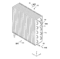
- FIG. 1 is a perspective view showing the configuration of the heat exchanger 100 according to the first embodiment.
- the heat exchanger 100 is, for example, a fin-and-tube heat exchanger. As shown in FIG. 1, the heat exchanger 100 includes a plurality of heat transfer tubes 11 and a plurality of fins 12.
- each of the fins 12 is a rectangular flat plate-shaped member.
- the fins 12 are arranged in parallel at regular intervals, spaced apart from each other in the Y direction, so as to form a space through which air flows.
- the interval is referred to as a fin pitch.
- the fin pitch does not necessarily have to be constant and may be different.
- the fin pitch is the distance between the centers of adjacent fins 12 in the thickness direction.
- the fin 12 is made of, for example, aluminum, but is not particularly limited. In the following, the direction in which the air flows indicated by the arrow R1 is referred to as the X direction (third direction).
- the longitudinal direction of the fin 12 is referred to as a Z direction (second direction).
- the stacking direction of the fins 12 is referred to as a Y direction (first direction).
- the X and Z directions are orthogonal to each other.
- the X direction and the Y direction are orthogonal to each other.
- the Y direction and the Z direction are orthogonal to each other.
- the plurality of heat transfer tubes 11 are arranged so as to penetrate the fins 12. Therefore, the longitudinal direction of the heat transfer tube 11 is the Y direction. Further, the heat transfer tubes 11 are arranged in parallel at regular intervals, spaced apart from each other in the Z direction. Hereinafter, the interval is referred to as a pipe pitch.
- the tube pitch does not necessarily have to be constant and may vary.
- the tube pitch is the distance between the centers of adjacent heat transfer tubes 11 in the Z direction.
- the refrigerant flows inside the heat transfer tube 11.
- the ends of the heat transfer tubes 11 adjacent to each other in the Z direction are connected by a U-shaped tube 11a.
- the heat transfer tube 11 does not necessarily have to be connected to one.
- the heat transfer tube 11 is made of a metal having high heat transfer properties such as copper or a copper alloy, but is not particularly limited.
- FIG. 2 is a partial side sectional view showing only the basic configuration of the heat exchanger 100 of FIG.
- FIG. 2 shows a cross section when cut at one point in the Y direction.
- FIG. 2 shows the main surface of the fin 12 and the cross section of the heat transfer tube 11.
- Each of the heat transfer tubes 11 is composed of, for example, a circular tube or a flat tube. 1 and 2 show a case where the heat transfer tube 11 is a circular tube.
- the heat exchanger 100 exchanges heat between the air flowing along the main surface of the fin 12 and the refrigerant flowing inside the heat transfer tube 11.
- the heat exchanger 100 is arranged so that air flows in the X direction.
- the Z direction orthogonal to the X direction is, for example, a vertical direction.
- the Z direction is referred to as the row direction of the heat transfer tubes 11 and the Y direction is referred to as the step direction of the heat transfer tubes 11, in the example of FIG. 1, the heat transfer tubes 11 have 12 steps in one row.
- FIG. 3 is a perspective view showing a modified example of the heat exchanger 100 shown in FIG.
- the position of the heat transfer tube 11 in the first row and the position of the heat transfer tube 11 in the second row are deviated by 1/2 of the tube pitch in the Z direction as shown in FIG. 21 described later.
- the fins 12 in the first row and the fins 12 in the second row are divided, but as shown in FIG. 3, undivided fins 12 may be used.
- the number of stages in the first row and the number of stages in the second row are different.
- the first row has 12 steps
- the second row has 10 steps.
- the number of stages of the heat transfer tube 11 is not limited to these cases, and may be arbitrarily determined.
- the ends of the heat transfer tubes 11 adjacent to each other in the Z direction are connected by the U-shaped tube 11a.
- the plurality of heat transfer tubes 11 are connected to one so that the refrigerant flows in order.
- the heat transfer tubes 11 do not necessarily have to be connected to one.
- FIGS. 1 and 3 show a case where the longitudinal direction of the heat transfer tube 11 extends in the Y direction.
- the Y direction is, for example, the horizontal direction.
- the longitudinal direction of the heat transfer tube 11 may extend in the vertical direction.
- the longitudinal direction of the fin 12 is the horizontal direction.
- FIG. 4 is a refrigerant circuit diagram showing an example of the configuration of the refrigeration cycle device 1 according to the first embodiment. As shown in FIG. 4, the refrigeration cycle device 1 includes a heat source side unit 2 and a load side unit 3.
- the heat source side unit 2 and the load side unit 3 are connected to each other by the refrigerant pipe 8.
- the heat exchanger 100 can be used in both the heat source side unit 2 and the load side unit 3.
- the heat exchanger 100 arranged in the heat source side unit 2 is referred to as a heat exchanger 100A
- the heat exchanger 100 arranged in the load side unit 3 is referred to as a heat exchanger 100B.
- the load side unit 3 includes a heat exchanger 100B, a blower 7B, a controller 9B, and a part of the refrigerant pipe 8.
- the blower 7B blows air to the heat exchanger 100B.
- the heat exchanger 100B exchanges heat between the refrigerant flowing through the heat transfer tube 11 and air.
- the heat exchanger 100B functions as a condenser when the refrigeration cycle device 1 heats the load side unit 3 side, and functions as an evaporator when the load side unit 3 side is cooled.
- the blower 7B is, for example, a propeller fan.
- the blower 7B is composed of a fan motor 7a and a fan 7b.
- the fan 7b rotates using the fan motor 7a as a power source.
- the rotation speed of the blower 7B is controlled by the controller 9B.
- the heat source side unit 2 includes a heat exchanger 100A, a controller 9A, a compressor 4, a flow path switching device 5, an expansion valve 6, a blower 7A, and a refrigerant pipe 8. Has a part of.
- the heat source side unit 2 may further include other components such as an accumulator.
- the heat exchanger 100A exchanges heat between the refrigerant flowing through the heat transfer tube 11 and the air.
- the heat exchanger 100A functions as an evaporator when the refrigeration cycle device 1 heats the load side unit 3 side, and functions as a condenser when the load side unit 3 side is cooled.
- the blower 7A blows air to the heat exchanger 100A.
- the blower 7A is, for example, a propeller fan.
- the blower 7A is composed of a fan motor 7a and a fan 7b, similarly to the blower 7B.
- the rotation speed of the blower 7A is controlled by the controller 9A.
- the compressor 4 sucks in a low-pressure gas refrigerant, compresses it, and discharges it as a high-pressure gas refrigerant.
- the compressor 4 is, for example, an inverter compressor.
- the inverter compressor can change the amount of the refrigerant to be sent out per unit time by controlling the inverter circuit or the like.
- the inverter circuit is mounted on the controller 9A, for example.
- the flow path switching device 5 is a valve for switching the flow direction of the refrigerant in the refrigerant pipe 8.
- the flow path switching device 5 is composed of, for example, a four-way valve.
- the flow path switching device 5 is switched between the case where the refrigerating cycle device 1 is in the cooling operation and the case where the refrigerating cycle device 1 is in the heating operation under the control of the controller 9A.
- the flow path switching device 5 is in the state shown by the solid line in FIG.
- the refrigerant discharged from the compressor 4 flows into the heat exchanger 100A arranged in the heat source side unit 2.
- the expansion valve 6 decompresses the inflowing liquid refrigerant by a squeezing action and flows out so that the refrigerant liquefied by the condenser can be easily evaporated by the evaporator. Further, the expansion valve 6 adjusts the amount of refrigerant so as to maintain an appropriate amount of refrigerant according to the load of the evaporator.
- the expansion valve 6 is composed of, for example, an electronic expansion valve.
- the opening degree of the expansion valve 6 is controlled by the controller 9A. As shown in FIG. 4, the expansion valve 6 is connected between the heat exchanger 100A and the heat exchanger 100B by a refrigerant pipe 8.
- the refrigerant pipe 8 is connected to the compressor 4, the flow path switching device 5, the heat exchanger 100A, the expansion valve 6, and the heat exchanger 100B to form a refrigerant circuit.
- the refrigerant pipe 8 is connected to the heat transfer tube 11 of the heat exchanger 100A and the heat transfer tube 11 of the heat exchanger 100B.
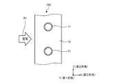
- FIG. 5 is a partial side sectional view of the heat exchanger 100 of FIG. FIG. 5 shows the main surface of the fin 12. Further, FIG. 5 shows a cross section of the heat transfer tube 11.
- the cross section of the heat transfer tube 11 shown in FIG. 5 is a cross section parallel to the main surface of the fin 12.
- the heat transfer tubes 11 are arranged in a row along the Z direction.
- the fin 12 has a leading edge 12a and a trailing edge 12b. Since the air flows in the direction of the arrow R1 in FIG. 5, the leading edge 12a is arranged on the windward side with respect to the trailing edge 12b.
- the heat transfer tube 11 is inserted into the through hole 12c formed in the fin 12.
- the outer diameter of the heat transfer tube 11 corresponds to the inner diameter of the through hole 12c. Therefore, the heat transfer tube 11 is in close contact with the inner wall of the through hole 12c.
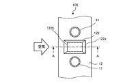
- the main surface of the fin 12 constitutes a flat fin base surface 121.
- the fin base surface 121 is provided with a fin protrusion 122.
- the fin protrusion 122 projects in the Y direction from the fin base surface 121, which is one of the main surfaces of the fin 12.
- the fin protrusion 122 is arranged between the adjacent heat transfer tubes 11 among the plurality of heat transfer tubes 11. As shown in FIG. 5, the fin protrusion 122 has a rectangular shape when viewed from the front.
- the “front view” refers to a case where the main surface of the fin 12 provided with the fin protrusion 122 is viewed in the Y direction, as shown in FIG.
- the fin protrusion 122 has an upper end portion 122u, a lower end portion 122d, and two side end portions 122s.
- the upper end portion 122u, the lower end portion 122d, and the two side end portions 122s extend linearly.
- the upper end portion 122u and the lower end portion 122d form a long side of a rectangle and face each other.
- the two side ends 122s form a rectangular short side and face each other.
- the direction in which the upper end portion 122u and the lower end portion 122d extend is the X direction
- the direction in which the two side end portions 122s extend is the Z direction.
- the fin protrusion 122 has a rising portion 122a and a main portion 122b.
- the rising portion 122a has a rectangular frame shape when viewed from the front.
- the main portion 122b has a rectangular shape when viewed from the front.
- the main portion 122b is arranged inside the rising portion 122a. That is, the rising portion 122a is arranged so as to surround the periphery of the main portion 122b.
- the area of the main portion 122b is larger than the area of the rising portion 122a. Further, the center position of the rising portion 122a and the center position of the main portion 122b coincide with each other.
- the central position of the rising portion 122a is an intersection of diagonal lines connecting the vertices of the outer shape of the rising portion 122a.
- the central position of the main portion 122b is an intersection of diagonal lines connecting the vertices of the outer shape of the main portion 122b.
- the center position of the main portion 122b and the center position of the rising portion 122a coincide with the center of the fin 12 in the X direction.
- the main portion 122b has a quadrangular pyramid shape with a rectangular bottom surface. Further, the rising portion 122a has a quadrangular pyramid shape having a rectangular bottom surface. Therefore, the fin protrusion 122 is composed of a quadrangular pyramid-shaped rising portion 122a and a quadrangular pyramid-shaped main portion 122b provided above the rising portion 122a.
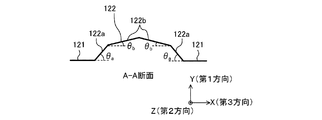
- FIG. 6 is a cross-sectional view taken along the line AA of FIG.
- the rising portion 122a is arranged between the fin base surface 121 and the main portion 122b. That is, the rising portion 122a connects the fin base surface 121 and the main portion 122b.
- ⁇ a be the angle formed by the surface of the rising portion 122a and the fin base surface 121.
- the angle formed by the surface of the main portion 122b and the fin base surface 121 is defined as ⁇ b.
- the angle ⁇ a and the angle ⁇ b have a relationship of ⁇ a> ⁇ b. That is, the inclination angle of the main portion 122b is smaller than the inclination angle of the rising portion 122a.
- the basic air flow will be described with reference to FIG.
- the air collides with the side end portion 122s of the fin protrusion 122, is divided into upper and lower parts, and flows to the windward side of the upper and lower heat transfer tubes 11. After that, a part of air flows between the heat transfer tube 11 and the fin protrusion 122. The air flows along the heat transfer tube 11 to the leeward side of the heat transfer tube 11. As a result, no dead water area is generated on the windward side and the leeward side of the heat transfer tube 11. Further, at the same time as the operation, as shown in FIG. 8 described later, air flows from the windward side to the leeward side beyond the fin protrusion 122.
- FIG. 7 is a diagram showing a cross section of the protrusion 500 described in Patent Document 1.
- FIG. 8 is an explanatory view in which an air flow is added to the cross-sectional view taken along the line AA of FIG.
- each arrow indicates the flow of air.
- the fin described in Patent Document 1 is formed with a regular quadrangular pyramid-shaped protrusion 500. Since the angle formed by the protrusion 500 and the main surface of the fin is large, the air flowing from the windward side cannot flow along the surface of the protrusion 500 on the leeward side. That is, as shown by the arrow in FIG.
- the inclination angle of the main portion 122b is smaller than the inclination angle of the rising portion 122a. Therefore, as shown in FIG. 8, air tends to flow along the fin protrusion 122. In particular, since the slope of the main portion 122b is gentle, the air flow is also gentle, and the air flows along the surface of the main portion 122b.
- the dead water area 201 is less likely to occur on the downstream side of the fin protrusion 122, and the dead water area 201 is significantly reduced as compared with the dead water area 501 of FIG.
- the dead water area 201 can be reduced.
- the area of the heat exchangeable region on the surface of the fin 12 becomes large.
- the heat transfer efficiency on the surface of the fin 12 is improved.
- FIG. 9 is a partial side sectional view showing a modification 1 of the fin 12 of the heat exchanger 100 according to the first embodiment.
- FIG. 9 shows the surface of the fin 12 and the cross section of the heat transfer tube 11 parallel to the main surface of the fin 12.
- FIG. 10 is a cross-sectional view taken along the line AA of FIG.
- the fin protrusion 122 has a rising portion 122a and a main portion 122b, as in the first embodiment.
- the definitions of the angle ⁇ a and the angle ⁇ b in the modified example 1 are the same as the definitions of the first embodiment shown in FIG. That is, the angle formed by the rising portion 122a and the fin base surface 121 is defined as ⁇ a, and the angle formed by the main portion 122b and the fin base surface 121 is defined as ⁇ b.
- FIG. 11 is an explanatory view in which an air flow is added to the cross-sectional view taken along the line AA of FIG.
- the inclination angle of the main portion 122b is smaller than the inclination angle of the rising portion 122a. Therefore, as shown in FIG. 11, air tends to flow along the fin protrusion 122.
- the main portion 122b is flat, air can flow more easily.
- the dead water area 201 generated on the downstream side of the fin protrusion 122 is reduced as in the first embodiment.
- the dead water area 201 is small, the area of the area where heat exchange is possible is large on the surface of the fin 12. As a result, the heat transfer efficiency on the surface of the fin 12 is improved as in the first embodiment.
- FIG. 12 is a partial side sectional view showing a modification 2 of the fin 12 of the heat exchanger 100 according to the first embodiment.
- FIG. 12 shows the surface of the fin 12 and the cross section of the heat transfer tube 11 parallel to the main surface of the fin 12.
- FIG. 13 is a cross-sectional view taken along the line AA of FIG.
- the fin protrusion 122 has a rising portion 122a and a main portion 122b, as in the first embodiment.
- the position of the apex of the main portion 122b is shifted closer to the leading edge 12a than the center of the fin 12 in the X direction.
- the main portion 122b has a leeward side main portion 122b-1 and a leeward side main portion 122b-2.
- the area of the leeward main portion 122b-1 is smaller than the area of the leeward main portion 122b-2.
- the windward main portion 122b-1 is a portion of the main portion 122b located on the windward side in the X direction.
- the windward main portion 122b-1 has a triangular shape when viewed from the front.
- the leeward side main portion 122b-2 is a portion of the main portion 122b located on the leeward side in the X direction.
- the leeward side main portion 122b-2 has a triangular shape when viewed from the front.
- the angle formed by the leeward main portion 122b-1 and the fin base surface 121 is ⁇ b1
- the angle formed by the leeward main portion 122b-2 and the fin base surface 121 is ⁇ b2.
- the angle ⁇ b1 and the angle ⁇ b2 have a relationship of ⁇ b1> ⁇ b2. That is, the inclination angle of the leeward side main portion 122b-2 is smaller than the inclination angle of the leeward side main portion 122b-1.
- the rising portion 122a has a leeward rising portion 122a-1 and a leeward rising portion 122a-2.
- the area of the leeward side riser 122a-1 is smaller than the area of the leeward side riser 122a-2.
- the windward rising portion 122a-1 is a portion of the rising portion 122a located on the windward side.
- the windward rising portion 122a-1 has a trapezoidal shape when viewed from the front.
- the leeward side rising portion 122a-2 is a portion of the rising portion 122a located on the leeward side.
- the leeward side rising portion 122a-2 has a trapezoidal shape when viewed from the front.
- the angle formed by the windward rising portion 122a-1 and the fin base surface 121 is ⁇ a1
- the angle formed by the leeward rising portion 122a-2 and the fin base surface 121 is ⁇ a2.
- the angle ⁇ a1 and the angle ⁇ a2 have a relationship of ⁇ a1> ⁇ a2. That is, the inclination angle of the leeward side riser 122a-2 is smaller than the inclination angle of the leeward side riser 122a-1.
- the angle ⁇ a1 and the angle ⁇ b1 have a relationship of ⁇ a1> ⁇ b1. Further, in the second modification, the angle ⁇ a2 and the angle ⁇ b2 have a relationship of ⁇ a2> ⁇ b2. That is, even in the modified example, the inclination angle of the main portion 122b is smaller than the inclination angle of the rising portion 122a.
- the relationship between the angle ⁇ a2 and the angle ⁇ b1 is preferably ⁇ a2> ⁇ b1, but may be the same, or may be ⁇ a2 ⁇ b1.
- FIG. 14 is an explanatory view in which an air flow is added to the cross-sectional view taken along the line AA of FIG.
- the inclination angle of the main portion 122b is smaller than the inclination angle of the rising portion 122a.
- the inclination angle on the leeward side is smaller than the inclination angle on the leeward side. Therefore, as shown in FIG. 14, air tends to flow along the fin protrusion 122.
- the dead water area 201 generated on the downstream side of the fin protrusion 122 is reduced as in the first embodiment.
- the dead water area 201 since the dead water area 201 is small, the area of the area where heat exchange is possible is large on the surface of the fin 12. As a result, the heat transfer efficiency on the surface of the fin 12 is improved as in the first embodiment.
- the angle ⁇ a1 formed by the leeward rising portion 122a-1 and the fin base surface 121 and the angle ⁇ a2 formed by the leeward rising portion 122a-2 and the fin base surface 121 are ⁇ a1> ⁇ a2.
- the dead water area 201 formed in the vicinity of the leeward side rising portion 122a-2 is further reduced as compared with the first embodiment, and the heat transfer efficiency on the surface of the fin 12 is further improved.
- the angle ⁇ b1 formed by the leeward main portion 122b-1 and the fin base surface 121 and the angle ⁇ b2 formed by the leeward side main portion 122b-2 and the fin base surface 121 are ⁇ b1> ⁇ b2.
- the air can flow more easily along the fin protrusion 122 as compared with the first embodiment.
- the dead water area 201 formed in the vicinity of the leeward side main portion 122b-2 is further reduced as compared with the first embodiment, and the heat transfer efficiency on the surface of the fin 12 is further improved.
- FIG. 15 is a cross-sectional view showing a modification 3 of the fin 12 of the heat exchanger 100 according to the first embodiment.
- the first embodiment as shown in FIG. 6, the case where the angle ⁇ a and the angle ⁇ b have a relationship of ⁇ a> ⁇ b has been described on both the leeward side and the leeward side.
- the angle ⁇ a and the angle ⁇ b have a relationship of ⁇ a> ⁇ b as in the first embodiment.
- the fin protrusion 122 has a rising portion 122a and a main portion 122b.
- the riser portion 122a has a windward side riser portion 122a-1 and a leeward side riser portion 122a-2.
- the angle formed by the windward rising portion 122a-1 and the fin base surface 121 is defined as ⁇ a1.
- the main portion 122b has a leeward side main portion 122b-1 and a leeward side main portion 122b-2.
- the angle formed by the windward main portion 122b-1 and the fin base surface 121 is defined as ⁇ b1.
- Embodiment 2 the heat exchanger 100 and the refrigeration cycle device 1 according to the second embodiment will be described.
- FIG. 17 is a partial side sectional view of the heat exchanger 100 of FIG. FIG. 17 shows the main surface of the fin 12 and the cross section of the heat transfer tube 11.
- the cross section of the heat transfer tube 11 shown in FIG. 17 is a cross section parallel to the main surface of the fin 12.
- the heat transfer tubes 11 are arranged in a row along the row direction parallel to the longitudinal direction of the fins 12.
- the fin 12 has a leading edge 12a and a trailing edge 12b. Since the air flows in the direction of the arrow R1, the leading edge 12a is arranged upwind with respect to the trailing edge 12b.
- the main surface of the fin 12 is a flat fin base surface 121.
- the fin base surface 121 is provided with a fin protrusion 122A.
- the fin protrusion 122A projects from one main surface of the fin 12.
- the fin protrusion 122A is arranged between the adjacent heat transfer tubes 11. As shown in FIG. 17, the fin protrusion 122A has a hexagonal shape when viewed from the front.
- the fin protrusion 122A has an upper end portion 122u, a lower end portion 122d, and two V-shaped side end portions 122s.
- the upper end portion 122u and the lower end portion 122d face each other.
- the upper end portion 122u and the lower end portion 122d extend linearly.
- the extending direction of the upper end portion 122u and the lower end portion 122d is the X direction.
- the V-shaped side ends 122s face each other. That is, each of the side end portions 122s is formed in a tapered shape.
- the tip of the side end portion 122s on the windward side becomes thinner toward the leading edge 12a of the fin 12.
- the tip of the leeward side end 122s becomes thinner toward the trailing edge 12b of the fin 12.
- the windward side end 122s is composed of a first inclined end 122s-1 and a second inclined end 122s-2.
- the first inclined end 122s-1 and the second inclined end 122s-2 are arranged in a V shape.
- the first inclined end 122s-1 is inclined from the X direction to the Z direction.
- the second inclined end 122s-2 is inclined from the X direction to the ⁇ Z direction. These inclination angles are, for example, about 40 to 60 degrees.
- the first inclined end 122s-1 and the second inclined end 122s-2 are each from the third direction to the third direction. It is inclined in two directions.
- the leeward side end 122s is composed of a third inclined end 122s-3 and a fourth inclined end 122s-4.
- the third inclined end 122s-3 and the fourth inclined end 122s-4 are arranged in a V shape.
- the third inclined end 122s-3 is inclined from the ⁇ X direction to the Z direction.
- the fourth inclined end 122s-4 is inclined from the ⁇ X direction to the ⁇ Z direction.
- These inclination angles ⁇ are, for example, about 40 to 60 degrees.
- the third inclined end 122s-3 and the fourth inclined end 122s-4 are respectively. , Inclined from the third direction to the second direction.
- the width of the fin protrusion 122A in the Z direction increases from the upstream end to the middle portion of the fin protrusion 122A along the X direction in which air flows, and then becomes constant in the middle portion and becomes constant from the middle portion to the downstream end. Will decrease.
- the fin protrusion 122 has a rising portion 122a and a main portion 122b.
- the rising portion 122a has a hexagonal frame shape when viewed from the front.
- the main portion 122b has a hexagonal shape when viewed from the front.
- the main portion 122b is arranged inside the rising portion 122a. That is, the rising portion 122a is arranged so as to surround the main portion 122b.
- the area of the main portion 122b is larger than the area of the rising portion 122a.
- the center position of the rising portion 122a and the center position of the main portion 122b coincide with each other.
- the central position of the rising portion 122a is an intersection of diagonal lines connecting the vertices of the outer shape of the rising portion 122a.
- the central position of the main portion 122b is an intersection of diagonal lines connecting the vertices of the outer shape of the main portion 122b.
- the main portion 122b has a hexagonal pyramid shape with a hexagonal bottom surface. Further, the rising portion 122a has a hexagonal frustum shape having a hexagonal bottom surface. Therefore, the fin protrusion 122 is composed of a hexagonal frustum-shaped rising portion 122a and a hexagonal pyramid-shaped main portion 122b provided above the rising portion 122a.
- the rising portion 122a has two windward inclined surfaces 122g, two leeward inclined surfaces 122h, an upper inclined surface 122e, and a lower inclined surface 122f.
- Each of the windward inclined surfaces 122g has a first inclined end 122s-1 and a second inclined end 122s-2 having an inclination angle from the third direction to the second direction.
- each of the leeward inclined surfaces 122h has a third inclined end 122s-3 and a fourth inclined end 122s-4 extending from the third direction to the second direction.
- FIG. 18 is a cross-sectional view taken along the line AA of FIG.
- the rising portion 122a is formed between the fin base surface 121 and the main portion 122b. Further, the main portion 122b is formed so as to be surrounded by the rising portion 122a.
- ⁇ a be the angle formed by the rising portion 122a with respect to the fin base surface 121. Further, the angle formed by the main portion 122b with respect to the fin base surface 121 is defined as ⁇ b. At this time, the angle ⁇ a and the angle ⁇ b have a relationship of ⁇ a> ⁇ b.
- reference numeral P is a downstream end of the windward inclined surface 122 g. As shown by the arrow Q, the downstream end P is arranged on the upstream side of the center of the heat transfer tube 11.
- FIG. 19 is an explanatory view in which an air flow is added to the cross-sectional view taken along the line AA of FIG.
- the inclination angle of the main portion 122b is smaller than the inclination angle of the rising portion 122a. Therefore, as shown in FIG. 19, air tends to flow along the fin protrusion 122.
- the dead water area 201 generated on the downstream side of the fin protrusion 122 is significantly reduced as compared with the dead water area 501 in Patent Document 1 shown in FIG.
- the dead water area 201 is small, the area of the area where heat exchange is possible is large on the surface of the fin 12. As a result, the heat transfer efficiency on the surface of the fin 12 is improved.
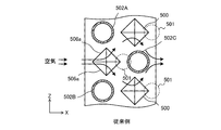
- FIG. 20 is a front view showing the protrusion 500 described in Patent Document 1.
- reference numeral 502 is a heat transfer tube.
- FIG. 21 is a front view showing the fin protrusion 122A according to the second embodiment. Note that FIG. 21 shows a case where the heat transfer tubes 11 are arranged in two rows for comparison with FIG. 20. That is, the case where the fin protrusion 122A of the second embodiment is applied to the heat exchanger 100 shown in FIG. 3 is shown.
- the fins 12 are provided in common with respect to the two rows of heat transfer tubes 11, but not limited to this case, as shown in FIG. 21, the fins 12 are arranged in each row. May be good. That is, in FIG. 21, each of the fins 12 of FIG. 3 is divided and arranged for each row.
- Patent Document 1 when air collides with the protrusion 500 in the first row, the air is divided into two upper and lower parts. One air is guided to the heat transfer tube 502A side by the inclined surface 506a of the protrusion 500, and the other air is guided to the heat transfer tube 502B side by the inclined surface 506b of the protrusion 500. Each of the induced air collides with the protrusion 500 in the second row, and as a result, wraps around behind the heat transfer tube 502C in the second row. Therefore, as shown by the broken line in FIG. 20, a dead water area 501 is generated on the leeward side of each protrusion 500.
- the air flowing in the direction indicated by the arrow 33 passes through the leeward side of the heat transfer tube 11A and flows to the fin protrusion 122A side of the second row. As a result, a dead water area cannot be created on the leeward side of the heat transfer tube 11A. After that, the air is guided to the area 42 by the windward inclined surface 122g of the fin protrusion 122A in the second row, as shown by the arrow 35. The air collides with the heat transfer tube 11B in the area 42 and separates into two. One air is guided to the windward side of the second row heat transfer tube 11B, as indicated by the arrow 36.
- the other air also flows along the lower inclined surface 122f of the fin protrusion 122, as indicated by the arrow 37. After that, a part of the air is guided to the leeward inclined surface 122h and flows to the area 43 behind the fin protrusion 122A as shown by the arrow 38. The remaining air flows outward from the trailing edge 12b of the fin 12, as indicated by arrow 39.
- FIG. 21 describes the case where the heat transfer tubes 11 are provided in two rows, the same effect can be obtained when the heat transfer tubes 11 are provided in one row. That is, the operation of (1) is performed on the upper side of the fin protrusion 122A, and the operation of (2) is performed on the lower side of the fin protrusion 122A. Therefore, the same effect can be obtained regardless of whether the heat transfer tubes 11 are in a single row or in a plurality of cases.
- the rising portion 122a has the leeward side inclined surface 122h on the leeward side.
- the leeward inclined surface 122h has a third inclined end 122s-3 and a fourth inclined end 122s-4 inclined from the third direction to the second direction.
- air easily flows from the heat transfer tube 11 side to the leeward side of the fin protrusion 122A.
- the dead water area 201 generated on the leeward side of the fin protrusion 122A can be reduced as shown in FIG. 19, and the heat transfer rate of the fin 12 can be improved.
- the rising portion 122a has a plurality of windward inclined surfaces 122g on the windward side.
- the windward inclined surface 122g has a first inclined end 122s-1 and a second inclined end 122s-2 inclined from the third direction to the second direction.
- the downstream end P of the windward inclined surface 122 g is located on the upstream side of the center of the heat transfer tube 11.
- air easily flows to the windward side of the heat transfer tube 11 from the fin protrusion 122A side.
- the windward side of the heat transfer tube 11 is a region close to the heat source temperature. In the second embodiment, the flow velocity of the air passing through the region close to the heat source temperature is increased, so that the heat flux is improved.
- the angle ⁇ a of the rising portion 122a and the angle ⁇ b of the main portion 122b have a relationship of ⁇ a> ⁇ b, so that the same as in the first embodiment. The effect of can be obtained.
- the angle ⁇ a1 on the windward side and the angle ⁇ a2 on the leeward side may be different values in the rising portion 122a. good. Further, in the main portion 122b, the angle ⁇ b1 on the leeward side and the angle ⁇ b2 on the leeward side may be different values. In that case, the same effect as that of the second modification of the first embodiment can be obtained.
- Embodiment 3 the heat exchanger 100 and the refrigeration cycle device 1 according to the third embodiment will be described.
- FIG. 22 is a partial side sectional view of the heat exchanger 100 of FIG. FIG. 22 shows the surface of the fin 12. Further, FIG. 22 shows a cross section of the heat transfer tube 11. The cross section of the heat transfer tube 11 shown in FIG. 22 is a cross section parallel to the main surface of the fin 12. As shown in FIG. 22, the heat transfer tubes 11 are arranged in a row along the Z direction.
- the fin 12 has a leading edge 12a and a trailing edge 12b. Since the air flows in the direction of the arrow R1 in FIG. 5, the leading edge 12a is arranged upwind with respect to the trailing edge 12b.
- the main surface of the fin 12 is a flat fin base surface 121.
- the fin base surface 121 is provided with a fin protrusion 122B.
- the fin protrusion 122B projects from one main surface of the fin 12.
- the fin protrusion 122B is arranged between the adjacent heat transfer tubes 11. As shown in FIG. 22, the fin protrusion 122B has a hexagonal shape when viewed from the front.
- the fin protrusion 122B has an upper end portion 122u, a lower end portion 122d, and two V-shaped side end portions 122s.
- the upper end portion 122u and the lower end portion 122d face each other.
- the extending direction of the upper end portion 122u and the lower end portion 122d is the X direction.
- the fin protrusion 122B has a rising portion 122a and a main portion 122b.
- the main portion 122b is flat as in the first modification of the second embodiment.
- the configuration up to this point is the same as that of the first modification of the second embodiment.
- the fin protrusion 122B is divided into three blocks. These blocks are hereinafter referred to as fin protrusions 122B-1, 122B-2, and 122B-3. Therefore, the fin protrusion 122B is composed of the fin protrusions 122B-1, 122B-2, and 122B-3.
- a plurality of fin protrusions 122B-1, 122B-2, and 122B- are provided between the heat transfer tubes 11 adjacent to each other in the Z direction along the Z direction. 3 is provided.
- the fin protrusion 122B-1 has a trapezoidal shape when viewed from the front.
- the trapezoidal upper base of the fin protrusion 122B-1 is shorter than the lower base.
- the fin protrusion 122B-2 is arranged below the fin protrusion 122B-1.
- the fin protrusion 122B-2 has a hexagonal shape when viewed from the front.
- the fin protrusion 122B-3 is arranged below the fin protrusion 122B-2.
- the fin protrusion 122B-3 has a trapezoidal shape when viewed from the front.
- the trapezoidal upper base of the fin protrusion 122B-3 is longer than the lower base.
- Each of the fin protrusions 122B-1, 122B-2, and 122B-3 has a rising portion 122a and a flat main portion 122b.
- a ventilation groove 130 is formed between the fin protrusion 122B-1 and the fin protrusion 122B-2. Similarly, a ventilation groove 130 is formed between the fin protrusion 122B-2 and the fin protrusion 122B-3. The direction in which these ventilation grooves 130 extend is the X direction. As described above, in the third embodiment, a groove extending in the X direction is provided between the fin protrusions 122B-1, 122B-2, and 122B-3 adjacent to each other in the Z direction.
- FIG. 23 is a cross-sectional view taken along the line BB of FIG. As shown in FIG. 23, the height of the bottom portion 130a of the ventilation groove 130 in the Y direction is the same as that of the fin base surface 121.
- the third embodiment has the hexagonal fin protrusion 122B in the front view as in the second embodiment. Therefore, the same effect as that of the second embodiment can be obtained.
- the fin protrusion 122B is divided. That is, a plurality of fin protrusions 122B-1, 122B-2, and 122B-3 are arranged along the Z direction between the heat transfer tubes 11 adjacent to each other in the Z direction.
- a ventilation groove 130 extending in the X direction is provided between the fin protrusions 122B-1, 122B-2 and 122B-3. As shown in FIG. 22, the extending direction of the ventilation groove 130 is the same as the direction in which air flows.
- FIG. 24 is a cross-sectional view taken along the line AA of FIG. 22. As shown by the broken line arrow in FIG. 24, since air flows in the ventilation groove 130, the heat transfer area is further expanded as compared with the first and second embodiments. As a result, the heat transfer coefficient of the fin 12 is further improved.
- FIG. 25 is a front view showing the fin protrusion 122B according to the first modification of the third embodiment.
- FIG. 26 is a cross-sectional view taken along the line BB of FIG.
- the configuration of the fin protrusion 122B according to the first modification of the third embodiment is basically the same as that of the third embodiment.
- the height of the bottom 130a of the ventilation groove 130 in the Y direction is different from that of the fin base surface 121.
- the first modification differs from the third embodiment only in this respect.
- the height of the bottom 130a of the ventilation groove 130 in the Y direction is higher than that of the fin base surface 121.
- the height of the bottom portion 130a of the ventilation groove 130 in the Y direction may be lower than that of the fin base surface 121.
- FIG. 27 is a front view showing the fin protrusion 122C according to the second modification of the third embodiment.
- FIG. 28 is a cross-sectional view taken along the line AA of FIG. 27.
- the configuration of the fin protrusion 122C according to the second modification of the third embodiment is basically the same as that of the fin protrusion 122B of the third embodiment.
- a drainage groove 140 extending in the Z direction is provided in the central portion of the fin protrusion 122B of the third embodiment.
- the second modification differs from the third embodiment only in this respect.
- the height of the bottom 140a of the drainage groove 140 in the Y direction is the same as that of the fin base surface 121.
- the height of the bottom portion 140a of the drainage groove 140 in the Y direction may be higher or lower than that of the fin base surface 121.
- FIG. 29 is a front view showing a protrusion 500 provided on the fin of Patent Document 1.
- FIG. 30 is an explanatory view in which a water flow is added to FIG. 27 showing a modification 2 of the third embodiment.
- the drainage groove 140 extending in the Z direction is provided in the central portion of the fin protrusion 122C. Therefore, as shown by the arrow in FIG. 30, the condensed water flows downward through the drainage ditch 140. Therefore, the condensed water easily flows, and the drainage route of the condensed water becomes short. As a result, the condensed water can be efficiently discharged to the outside of the heat exchanger 100.
- the fin protrusion 122C having a hexagonal bottom surface is provided on the surface of the fin 12, and thus the same as in the third embodiment. The effect of is obtained.
- the drainage groove 140 is provided in the fin protrusion 122C, the effect that the condensed water can be easily discharged can be obtained.
- the fin protrusion 122B is divided into three blocks arranged along the Z direction, and two ventilation grooves 130 extending in the X direction are provided between the blocks.
- the number of blocks and the number of ventilation grooves 130 are not limited to this. That is, when n is an arbitrary positive integer, the fin protrusion 122B is divided into n blocks arranged along the Z direction, and (n-1) ventilation grooves 130 extending in the X direction are formed between the blocks. It may be provided. Further, the number of drainage ditches 140 may be any number of 2 or more.
- the heat exchanger 100 described in the above-described embodiments 1 to 3 and their modified examples can be provided in the refrigeration cycle device 1 shown in FIG.
- the heat transfer area in the fin 12 is reduced by reducing the dead water area 201 generated by the fin protrusions 122, 122A, 122B, or 122C provided in the fin 12 of the heat exchanger 100.
Landscapes
- Engineering & Computer Science (AREA)
- Physics & Mathematics (AREA)
- Thermal Sciences (AREA)
- Mechanical Engineering (AREA)
- General Engineering & Computer Science (AREA)
- Geometry (AREA)
- Heat-Exchange Devices With Radiators And Conduit Assemblies (AREA)
Priority Applications (4)
| Application Number | Priority Date | Filing Date | Title |
|---|---|---|---|
| EP20928270.6A EP4130634B1 (en) | 2020-03-30 | 2020-03-30 | Heat exchanger and refrigeration cycle device |
| ES20928270T ES2987256T3 (es) | 2020-03-30 | 2020-03-30 | Intercambiador de calor y dispositivo de ciclo de refrigeración |
| JP2022512516A JP7309041B2 (ja) | 2020-03-30 | 2020-03-30 | 熱交換器および冷凍サイクル装置 |
| PCT/JP2020/014479 WO2021199121A1 (ja) | 2020-03-30 | 2020-03-30 | 熱交換器および冷凍サイクル装置 |
Applications Claiming Priority (1)
| Application Number | Priority Date | Filing Date | Title |
|---|---|---|---|
| PCT/JP2020/014479 WO2021199121A1 (ja) | 2020-03-30 | 2020-03-30 | 熱交換器および冷凍サイクル装置 |
Publications (1)
| Publication Number | Publication Date |
|---|---|
| WO2021199121A1 true WO2021199121A1 (ja) | 2021-10-07 |
Family
ID=77929795
Family Applications (1)
| Application Number | Title | Priority Date | Filing Date |
|---|---|---|---|
| PCT/JP2020/014479 Ceased WO2021199121A1 (ja) | 2020-03-30 | 2020-03-30 | 熱交換器および冷凍サイクル装置 |
Country Status (4)
| Country | Link |
|---|---|
| EP (1) | EP4130634B1 (https=) |
| JP (1) | JP7309041B2 (https=) |
| ES (1) | ES2987256T3 (https=) |
| WO (1) | WO2021199121A1 (https=) |
Families Citing this family (1)
| Publication number | Priority date | Publication date | Assignee | Title |
|---|---|---|---|---|
| KR20250081223A (ko) * | 2023-11-29 | 2025-06-05 | 엘지전자 주식회사 | 열교환기 |
Citations (12)
| Publication number | Priority date | Publication date | Assignee | Title |
|---|---|---|---|---|
| JPS5031568U (https=) * | 1973-07-17 | 1975-04-07 | ||
| JPS5086359U (https=) * | 1973-12-11 | 1975-07-23 | ||
| JPS5787979U (https=) * | 1980-11-13 | 1982-05-31 | ||
| JPS63294494A (ja) * | 1987-05-27 | 1988-12-01 | Nippon Denso Co Ltd | 熱交換器 |
| JPH10227589A (ja) * | 1996-12-12 | 1998-08-25 | Daikin Ind Ltd | ワッフル型クロスフィン熱交換器 |
| JP2005090939A (ja) * | 2003-09-15 | 2005-04-07 | Lg Electronics Inc | 熱交換器 |
| JP2006038419A (ja) * | 2004-07-30 | 2006-02-09 | Matsushita Electric Ind Co Ltd | 空気調和機 |
| WO2007108386A1 (ja) | 2006-03-23 | 2007-09-27 | Matsushita Electric Industrial Co., Ltd. | フィンチューブ型熱交換器、熱交換器用フィンおよびヒートポンプ装置 |
| JP2012163320A (ja) * | 2011-01-21 | 2012-08-30 | Daikin Industries Ltd | 熱交換器および空気調和機 |
| JP2014511992A (ja) * | 2011-04-21 | 2014-05-19 | エルジー エレクトロニクス インコーポレイティド | 熱交換器 |
| JP2015132468A (ja) * | 2015-04-22 | 2015-07-23 | 三菱電機株式会社 | 空気調和機の熱交換器 |
| JP2016183841A (ja) * | 2015-03-26 | 2016-10-20 | 株式会社富士通ゼネラル | 熱交換器 |
Family Cites Families (5)
| Publication number | Priority date | Publication date | Assignee | Title |
|---|---|---|---|---|
| JP2001174181A (ja) * | 1999-10-06 | 2001-06-29 | Mitsubishi Heavy Ind Ltd | フィンアンドチューブ熱交換器及びこれを備えた空気調和機 |
| JP4028591B2 (ja) * | 2006-04-21 | 2007-12-26 | 松下電器産業株式会社 | 伝熱フィンおよびフィンチューブ型熱交換器 |
| JP2008215670A (ja) * | 2007-03-01 | 2008-09-18 | Matsushita Electric Ind Co Ltd | 伝熱フィン、フィンチューブ型熱交換器および冷凍サイクル装置 |
| JP5072983B2 (ja) * | 2010-01-12 | 2012-11-14 | 三菱電機株式会社 | フィンチューブ型熱交換器およびこれを用いた空調装置 |
| WO2011096124A1 (ja) * | 2010-02-08 | 2011-08-11 | 住友軽金属工業株式会社 | フィン・アンド・チューブ式熱交換器 |
-
2020
- 2020-03-30 EP EP20928270.6A patent/EP4130634B1/en active Active
- 2020-03-30 WO PCT/JP2020/014479 patent/WO2021199121A1/ja not_active Ceased
- 2020-03-30 ES ES20928270T patent/ES2987256T3/es active Active
- 2020-03-30 JP JP2022512516A patent/JP7309041B2/ja active Active
Patent Citations (12)
| Publication number | Priority date | Publication date | Assignee | Title |
|---|---|---|---|---|
| JPS5031568U (https=) * | 1973-07-17 | 1975-04-07 | ||
| JPS5086359U (https=) * | 1973-12-11 | 1975-07-23 | ||
| JPS5787979U (https=) * | 1980-11-13 | 1982-05-31 | ||
| JPS63294494A (ja) * | 1987-05-27 | 1988-12-01 | Nippon Denso Co Ltd | 熱交換器 |
| JPH10227589A (ja) * | 1996-12-12 | 1998-08-25 | Daikin Ind Ltd | ワッフル型クロスフィン熱交換器 |
| JP2005090939A (ja) * | 2003-09-15 | 2005-04-07 | Lg Electronics Inc | 熱交換器 |
| JP2006038419A (ja) * | 2004-07-30 | 2006-02-09 | Matsushita Electric Ind Co Ltd | 空気調和機 |
| WO2007108386A1 (ja) | 2006-03-23 | 2007-09-27 | Matsushita Electric Industrial Co., Ltd. | フィンチューブ型熱交換器、熱交換器用フィンおよびヒートポンプ装置 |
| JP2012163320A (ja) * | 2011-01-21 | 2012-08-30 | Daikin Industries Ltd | 熱交換器および空気調和機 |
| JP2014511992A (ja) * | 2011-04-21 | 2014-05-19 | エルジー エレクトロニクス インコーポレイティド | 熱交換器 |
| JP2016183841A (ja) * | 2015-03-26 | 2016-10-20 | 株式会社富士通ゼネラル | 熱交換器 |
| JP2015132468A (ja) * | 2015-04-22 | 2015-07-23 | 三菱電機株式会社 | 空気調和機の熱交換器 |
Non-Patent Citations (1)
| Title |
|---|
| See also references of EP4130634A4 |
Also Published As
| Publication number | Publication date |
|---|---|
| EP4130634A1 (en) | 2023-02-08 |
| JP7309041B2 (ja) | 2023-07-14 |
| ES2987256T3 (es) | 2024-11-14 |
| EP4130634B1 (en) | 2024-06-19 |
| EP4130634A4 (en) | 2023-05-10 |
| JPWO2021199121A1 (https=) | 2021-10-07 |
Similar Documents
| Publication | Publication Date | Title |
|---|---|---|
| JP6710205B2 (ja) | 熱交換器及び冷凍サイクル装置 | |
| CN103348211B (zh) | 热交换器及空调装置 | |
| US12228350B2 (en) | Heat exchanger and refrigeration cycle apparatus | |
| JP6897372B2 (ja) | 熱交換器 | |
| JPWO2018003123A1 (ja) | 熱交換器及び冷凍サイクル装置 | |
| JP2011202855A (ja) | 冷蔵庫 | |
| JPWO2017183180A1 (ja) | 熱交換器 | |
| CN103765150A (zh) | 空调机 | |
| JP7292510B2 (ja) | 熱交換器及び空気調和機 | |
| JP6548749B2 (ja) | 冷凍サイクル装置及び扁平管熱交換器 | |
| EP3608618B1 (en) | Heat exchanger and refrigeration cycle device | |
| JP5608478B2 (ja) | 熱交換器及びそれを用いた空気調和機 | |
| US11573056B2 (en) | Heat exchanger, heat exchanger unit, and refrigeration cycle apparatus | |
| JP7305085B1 (ja) | 熱交換器および冷凍サイクル装置 | |
| JP7309041B2 (ja) | 熱交換器および冷凍サイクル装置 | |
| JP6678413B2 (ja) | 空気調和機 | |
| JP5081881B2 (ja) | 空気調和機 | |
| KR102078275B1 (ko) | 공기조화기의 열교환기 | |
| JP3584304B2 (ja) | 熱交換器及びこれを備えた空気調和機 | |
| JP7158601B2 (ja) | 熱交換器及び冷凍サイクル装置 | |
| WO2020012549A1 (ja) | 熱交換器、熱交換装置、熱交換器ユニット及び冷凍サイクル装置 | |
| WO2018207321A1 (ja) | 熱交換器及び冷凍サイクル装置 | |
| CN111981583A (zh) | 一种空调器室外机 | |
| WO2021234957A1 (ja) | 熱交換器及び該熱交換器を備えた空気調和機 | |
| JP6545357B2 (ja) | 熱交換器 |
Legal Events
| Date | Code | Title | Description |
|---|---|---|---|
| 121 | Ep: the epo has been informed by wipo that ep was designated in this application |
Ref document number: 20928270 Country of ref document: EP Kind code of ref document: A1 |
|
| ENP | Entry into the national phase |
Ref document number: 2022512516 Country of ref document: JP Kind code of ref document: A |
|
| NENP | Non-entry into the national phase |
Ref country code: DE |
|
| ENP | Entry into the national phase |
Ref document number: 2020928270 Country of ref document: EP Effective date: 20221031 |