EP4130334A1 - Gas distributor in semiconductor device and semiconductor device - Google Patents
Gas distributor in semiconductor device and semiconductor device Download PDFInfo
- Publication number
- EP4130334A1 EP4130334A1 EP21780980.5A EP21780980A EP4130334A1 EP 4130334 A1 EP4130334 A1 EP 4130334A1 EP 21780980 A EP21780980 A EP 21780980A EP 4130334 A1 EP4130334 A1 EP 4130334A1
- Authority
- EP
- European Patent Office
- Prior art keywords
- gas
- pipeline
- pipelines
- gas inlet
- sub
- Prior art date
- Legal status (The legal status is an assumption and is not a legal conclusion. Google has not performed a legal analysis and makes no representation as to the accuracy of the status listed.)
- Pending
Links
Images


Classifications
-
- C—CHEMISTRY; METALLURGY
- C23—COATING METALLIC MATERIAL; COATING MATERIAL WITH METALLIC MATERIAL; CHEMICAL SURFACE TREATMENT; DIFFUSION TREATMENT OF METALLIC MATERIAL; COATING BY VACUUM EVAPORATION, BY SPUTTERING, BY ION IMPLANTATION OR BY CHEMICAL VAPOUR DEPOSITION, IN GENERAL; INHIBITING CORROSION OF METALLIC MATERIAL OR INCRUSTATION IN GENERAL
- C23C—COATING METALLIC MATERIAL; COATING MATERIAL WITH METALLIC MATERIAL; SURFACE TREATMENT OF METALLIC MATERIAL BY DIFFUSION INTO THE SURFACE, BY CHEMICAL CONVERSION OR SUBSTITUTION; COATING BY VACUUM EVAPORATION, BY SPUTTERING, BY ION IMPLANTATION OR BY CHEMICAL VAPOUR DEPOSITION, IN GENERAL
- C23C16/00—Chemical coating by decomposition of gaseous compounds, without leaving reaction products of surface material in the coating, i.e. chemical vapour deposition [CVD] processes
- C23C16/44—Chemical coating by decomposition of gaseous compounds, without leaving reaction products of surface material in the coating, i.e. chemical vapour deposition [CVD] processes characterised by the method of coating
- C23C16/455—Chemical coating by decomposition of gaseous compounds, without leaving reaction products of surface material in the coating, i.e. chemical vapour deposition [CVD] processes characterised by the method of coating characterised by the method used for introducing gases into reaction chamber or for modifying gas flows in reaction chamber
- C23C16/45561—Gas plumbing upstream of the reaction chamber
-
- C—CHEMISTRY; METALLURGY
- C23—COATING METALLIC MATERIAL; COATING MATERIAL WITH METALLIC MATERIAL; CHEMICAL SURFACE TREATMENT; DIFFUSION TREATMENT OF METALLIC MATERIAL; COATING BY VACUUM EVAPORATION, BY SPUTTERING, BY ION IMPLANTATION OR BY CHEMICAL VAPOUR DEPOSITION, IN GENERAL; INHIBITING CORROSION OF METALLIC MATERIAL OR INCRUSTATION IN GENERAL
- C23C—COATING METALLIC MATERIAL; COATING MATERIAL WITH METALLIC MATERIAL; SURFACE TREATMENT OF METALLIC MATERIAL BY DIFFUSION INTO THE SURFACE, BY CHEMICAL CONVERSION OR SUBSTITUTION; COATING BY VACUUM EVAPORATION, BY SPUTTERING, BY ION IMPLANTATION OR BY CHEMICAL VAPOUR DEPOSITION, IN GENERAL
- C23C16/00—Chemical coating by decomposition of gaseous compounds, without leaving reaction products of surface material in the coating, i.e. chemical vapour deposition [CVD] processes
- C23C16/44—Chemical coating by decomposition of gaseous compounds, without leaving reaction products of surface material in the coating, i.e. chemical vapour deposition [CVD] processes characterised by the method of coating
- C23C16/4401—Means for minimising impurities, e.g. dust, moisture or residual gas, in the reaction chamber
-
- C—CHEMISTRY; METALLURGY
- C23—COATING METALLIC MATERIAL; COATING MATERIAL WITH METALLIC MATERIAL; CHEMICAL SURFACE TREATMENT; DIFFUSION TREATMENT OF METALLIC MATERIAL; COATING BY VACUUM EVAPORATION, BY SPUTTERING, BY ION IMPLANTATION OR BY CHEMICAL VAPOUR DEPOSITION, IN GENERAL; INHIBITING CORROSION OF METALLIC MATERIAL OR INCRUSTATION IN GENERAL
- C23C—COATING METALLIC MATERIAL; COATING MATERIAL WITH METALLIC MATERIAL; SURFACE TREATMENT OF METALLIC MATERIAL BY DIFFUSION INTO THE SURFACE, BY CHEMICAL CONVERSION OR SUBSTITUTION; COATING BY VACUUM EVAPORATION, BY SPUTTERING, BY ION IMPLANTATION OR BY CHEMICAL VAPOUR DEPOSITION, IN GENERAL
- C23C16/00—Chemical coating by decomposition of gaseous compounds, without leaving reaction products of surface material in the coating, i.e. chemical vapour deposition [CVD] processes
- C23C16/44—Chemical coating by decomposition of gaseous compounds, without leaving reaction products of surface material in the coating, i.e. chemical vapour deposition [CVD] processes characterised by the method of coating
- C23C16/455—Chemical coating by decomposition of gaseous compounds, without leaving reaction products of surface material in the coating, i.e. chemical vapour deposition [CVD] processes characterised by the method of coating characterised by the method used for introducing gases into reaction chamber or for modifying gas flows in reaction chamber
- C23C16/45563—Gas nozzles
- C23C16/45574—Nozzles for more than one gas
-
- C—CHEMISTRY; METALLURGY
- C23—COATING METALLIC MATERIAL; COATING MATERIAL WITH METALLIC MATERIAL; CHEMICAL SURFACE TREATMENT; DIFFUSION TREATMENT OF METALLIC MATERIAL; COATING BY VACUUM EVAPORATION, BY SPUTTERING, BY ION IMPLANTATION OR BY CHEMICAL VAPOUR DEPOSITION, IN GENERAL; INHIBITING CORROSION OF METALLIC MATERIAL OR INCRUSTATION IN GENERAL
- C23C—COATING METALLIC MATERIAL; COATING MATERIAL WITH METALLIC MATERIAL; SURFACE TREATMENT OF METALLIC MATERIAL BY DIFFUSION INTO THE SURFACE, BY CHEMICAL CONVERSION OR SUBSTITUTION; COATING BY VACUUM EVAPORATION, BY SPUTTERING, BY ION IMPLANTATION OR BY CHEMICAL VAPOUR DEPOSITION, IN GENERAL
- C23C16/00—Chemical coating by decomposition of gaseous compounds, without leaving reaction products of surface material in the coating, i.e. chemical vapour deposition [CVD] processes
- C23C16/44—Chemical coating by decomposition of gaseous compounds, without leaving reaction products of surface material in the coating, i.e. chemical vapour deposition [CVD] processes characterised by the method of coating
- C23C16/455—Chemical coating by decomposition of gaseous compounds, without leaving reaction products of surface material in the coating, i.e. chemical vapour deposition [CVD] processes characterised by the method of coating characterised by the method used for introducing gases into reaction chamber or for modifying gas flows in reaction chamber
- C23C16/45563—Gas nozzles
- C23C16/45578—Elongated nozzles, tubes with holes
-
- C—CHEMISTRY; METALLURGY
- C23—COATING METALLIC MATERIAL; COATING MATERIAL WITH METALLIC MATERIAL; CHEMICAL SURFACE TREATMENT; DIFFUSION TREATMENT OF METALLIC MATERIAL; COATING BY VACUUM EVAPORATION, BY SPUTTERING, BY ION IMPLANTATION OR BY CHEMICAL VAPOUR DEPOSITION, IN GENERAL; INHIBITING CORROSION OF METALLIC MATERIAL OR INCRUSTATION IN GENERAL
- C23C—COATING METALLIC MATERIAL; COATING MATERIAL WITH METALLIC MATERIAL; SURFACE TREATMENT OF METALLIC MATERIAL BY DIFFUSION INTO THE SURFACE, BY CHEMICAL CONVERSION OR SUBSTITUTION; COATING BY VACUUM EVAPORATION, BY SPUTTERING, BY ION IMPLANTATION OR BY CHEMICAL VAPOUR DEPOSITION, IN GENERAL
- C23C16/00—Chemical coating by decomposition of gaseous compounds, without leaving reaction products of surface material in the coating, i.e. chemical vapour deposition [CVD] processes
- C23C16/44—Chemical coating by decomposition of gaseous compounds, without leaving reaction products of surface material in the coating, i.e. chemical vapour deposition [CVD] processes characterised by the method of coating
- C23C16/455—Chemical coating by decomposition of gaseous compounds, without leaving reaction products of surface material in the coating, i.e. chemical vapour deposition [CVD] processes characterised by the method of coating characterised by the method used for introducing gases into reaction chamber or for modifying gas flows in reaction chamber
- C23C16/45523—Pulsed gas flow or change of composition over time
- C23C16/45525—Atomic layer deposition [ALD]
- C23C16/45544—Atomic layer deposition [ALD] characterized by the apparatus
Definitions
- the present disclosure generally relates to the semiconductor technology field and, more particularly, to a semiconductor apparatus and a gas distributor of the semiconductor apparatus.
- Atomic layer deposition technology is a thin film preparation technology that is adsorbed layer by layer on a substrate in a form of a single atomic layer.
- the atomic layer deposition technology mainly includes two reaction processes.
- a first reaction process includes that a first reaction precursor enters a reaction chamber and is fully adsorbed at the substrate, after reaching a saturated state, a purge gas enters the reaction chamber to remove the remaining reaction precursor and a by-product.
- a second reaction process includes that a second reaction precursor enters the reaction chamber, reacts with a base group adsorbed at a surface of the substrate, and releases a reaction by-product. After saturated adsorption is formed, the purge gas enters the reaction chamber to remove the remaining reaction precursors and their by-products.
- the present disclosure is intended to solve at least one of the technical problems in the existing technology and provides a semiconductor apparatus and a gas distributor of the semiconductor apparatus.
- the present disclosure provides a gas distributor in a semiconductor apparatus, including a distributor body, the distributor body including a gas outlet end surface, wherein the distributor body includes:
- the height of the gas distribution chamber at the inner peripheral edge is between 2 mm and 4 mm, and the height of the gas distribution chamber at the outer peripheral edge is between 0.5 mm and 1 mm.
- the gas distribution pipeline group includes a plurality of main pipelines.
- the plurality of main pipelines are radially arranged from the first gas inlet pipeline in different directions away from the first gas inlet pipeline. Ends of the plurality of main pipelines close to the first gas inlet pipeline are communicated with a gas outlet end of the first gas inlet pipeline.
- the gas distribution pipeline group further includes a plurality of sub-pipeline groups.
- the sub-pipeline groups are arranged in a one-to-one correspondence with the main pipelines.
- Each of the sub-pipeline groups includes a plurality of sub-pipelines arranged on two sides of the corresponding main pipeline and at a predetermined included angle with the corresponding main pipeline.
- a plurality of sub-pipelines of each of the sub-pipeline groups are located on a same side of the main pipeline being arranged at intervals along an extension direction of the main pipeline. An end of each of the sub-pipelines close to the main pipeline is communicated with the main pipeline.
- a plurality of gas outlets of the gas distribution pipeline group are arranged at the plurality of sub-pipelines.
- the gas distribution pipeline group further includes at least one connection pipeline; and the connection pipeline is communicated with the main pipeline and/or the sub-pipeline intersecting with an extension trajectory of the connection pipeline.
- each connection pipeline is an annular pipeline.
- a plurality of annular pipelines are included. Orthographic projections of the plurality of annular pipelines on a radial cross-section of the first gas inlet pipeline have different diameters and are concentrically arranged with an orthographic projection of an axis of the first gas inlet pipeline as a center. A radial distance between orthographic projections of any two neighboring annular pipelines is equal.
- the gas outlet of each of the sub-pipelines is located at a position where the sub-pipeline intersects with the connection pipeline.
- an inner diameter of the main pipeline gradually decreases, and from an end of the sub-pipeline close to the main pipeline to the other end away from the main pipeline, an inner diameter of the sub-pipeline gradually decreases.
- all sub-pipelines located between any two neighboring main pipelines are parallel to each other.
- the sub-pipelines located on the two sides of the main pipeline of a same sub-pipeline group are arranged symmetrically.
- the second gas inlet pipeline is an annular gas inlet pipeline arranged around the first gas inlet pipeline.
- the present disclosure further provides a semiconductor apparatus, including the gas distributor.
- a gas inlet end of the first gas inlet pipeline is configured to be communicated with the first reaction gas supply device.
- a gas inlet end of the second gas inlet pipeline is configured to be communicated with the second reaction gas supply device.
- the first reaction gas supply device is configured to provide a first reaction gas.
- the second reaction gas supply device is configured to provide a second reaction gas.
- a diffusion coefficient of the first reaction gas is greater than a diffusion coefficient of the second reaction gas.
- the semiconductor device further includes a gas inlet block arranged on the distributor body.
- a first transmission channel and a second transmission channel are arranged in the gas inlet block.
- the first transmission channel is configured to communicate the first gas inlet pipeline with the first reaction gas supply device.
- the second transmission channel is configured to communicate the second gas inlet pipeline with the second reaction gas supply device.
- a first sealing ring and a second sealing ring surrounding the first sealing ring are arranged between the gas inlet block and the distributor body.
- a connection position between the first transmission channel and the first gas inlet pipeline is located on an inner side of the first sealing ring.
- a connection position between the second transmission channel and the second gas inlet pipeline is located between the first sealing ring and the second sealing ring.
- the reaction gas that is easy to diffuse and purge can be introduced into the gas distribution pipeline group from the first gas inlet pipeline. After being distributed by the gas distribution pipeline group, the reaction gas may be output from the first gas outlet pipelines.
- the reaction gas that is sticky, easy to condense, and difficult to purge may be introduced into the gas distribution chamber from the second gas inlet pipeline. After such reaction gas diffuses in the gas distribution chamber, the reaction gas can be output from the second gas outlet pipelines.
- the gas distribution chamber may be more beneficial for the gas to diffuse, and the residue is not easy to remain, which can avoid the situation that chemical vapor deposition occurs at the gas outlet due to the gas residue in the pipeline in the gas distribution chamber.
- the uniformity of the thin film deposited on the substrate may be improved.
- the height of the gas distribution chamber to gradually decrease from the inner peripheral edge close to the first gas inlet pipeline to the outer peripheral edge away from the first gas inlet pipeline, the volume of the gas distribution chamber may gradually decrease from inside to outside.
- the gas pressure in the gas distribution chamber may be balanced to further help increase the gas diffusion rate.
- the gas distribution chamber is an integral empty chamber, no dead angle position exists.
- the residue of the reaction gas is not easy to remain, which facilitates the cleaning of the gas distributor and improves the application lifetime of the gas distributor.
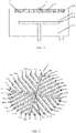
- FIG. 1 is a schematic diagram of an atomic layer deposition apparatus according to embodiments of the present disclosure.
- the reaction chamber 1 is provided with a base 3 and a gas distributor 4.
- a gas distribution pipeline 6 is formed in the gas distributor 4.
- a specific structure of an existing gas distribution pipeline 6 is shown in FIG. 2 .
- In the gas distribution pipeline 6, inner ends of four main distribution pipelines 8, 9, 10, and 11 are connected together and mutually communicated.
- Distribution branches are arranged on both sides of each of the main distribution pipelines, including distribution branches 8-1 to 8-8, distribution branches 9-1 to 9-8, distribution branches 10-1 to 10-8, and distribution branches 11-1 to 11-8.
- a plurality of gas outlet pipelines 7 are evenly distributed under the distribution branches.
- the gas provided by a gas source enters the gas distribution network 6 through the gas inlet pipeline 5, and after diffusing in the gas distribution network 6, is evenly sprayed on the substrate 2 that is to be deposited with the film through the gas outlet pipelines 7.
- the double-layered gas distribution pipelines 6 may be configured to transmit two kinds of reaction gases, respectively.
- the above-mentioned gas distribution pipeline 6 may easily realize rapid transfer and purging of a reaction gas, such as NH 3 , O 2 , Ar, and N 2 , which are easy to diffuse and easy to purge.
- a reaction gas such as gasified H 2 O, TMA, TiCl 4 , PDMAT, etc., which are sticky, easy to condense coldly, and not easy to purge, when such the gas is transmitted by the above-mentioned gas distribution pipeline 6, residue may easily remain in the pipeline.
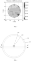
- FIG. 3 is a schematic diagram showing a thickness distribution of a film deposited by an existing gas distributor. It can be seen from FIG. 3 that the thickness uniformity of the thin film is poor.
- FIG. 4 is a schematic top view of the gas distributor according to embodiments of the present disclosure.
- FIG. 5 is a schematic cross-section along line A-A' in FIG. 4 .
- FIG. 6 is a schematic cross-section along line B-B' in FIG. 4 .
- the gas distributor includes a distributor body 110.
- the distributor body 110 includes a gas outlet end surface 111.
- a gas distribution pipeline group 120, a first gas inlet pipeline 130, and a plurality of first gas outlet pipelines 140 are arranged in the distributor body 110.
- a gas outlet end of the first gas inlet pipeline 130 is communicated with the gas inlet of the gas distribution pipeline group 120.
- Gas inlet ends of the plurality of first gas outlet pipelines 140 correspond to a plurality of gas outlets of the gas distribution pipeline group 120 in a one-to-one correspondence.
- the distributor body 110 further includes a gas distribution chamber 150 (a shaded area shown in FIG. 5 and FIG. 6 ), a second gas inlet pipeline 160, and a plurality of second gas outlet pipelines 170.
- the gas distribution chamber 150 is located above the gas distribution pipeline group 120 and is arranged around the first gas inlet pipeline 130.
- the gas outlet end of the second gas inlet pipeline 160 is communicated with the gas inlet of the gas distribution chamber 150.
- the gas inlet ends of the plurality of second gas outlet pipelines 170 are communicated with the plurality of gas outlets of the gas distribution chamber 150 in a one-to-one correspondence.
- the first gas outlet pipelines 140 and the second gas outlet pipelines 170 are arranged alternately.
- the gas outlet ends of the first gas outlet pipelines 140 and the second gas outlet pipelines 170 are located on the gas outlet end surface 111 of the distributor body 110. It should be understood that the gas distribution chamber 150 being located above the gas distribution pipeline group 120 may indicate that the gas distribution chamber 150 is located on a side of the gas distribution pipeline group 120 away from the gas outlet end surface 111.
- the gas distribution chamber 150 may be an empty chamber surrounding the first gas inlet pipeline 130.
- the empty chamber may have a continuous integral structure. No structural member that affects gas flow may be arranged in the gas distribution chamber 150.
- the gas distribution chamber may be more beneficial for gas diffusion, and the residue may not be easy to occur.
- the reaction gas that is sticky, easy to condense coldly, and not easy to purge, the situation of the chemical vapor deposition occurring at the gas outlet due to the residue of such the gas in the pipeline may be prevented in the gas distribution chamber.
- the uniformity of the thin film deposited on the substrate may be improved.
- the air inlet of the gas distribution chamber 150 is located at a position close to an inner peripheral edge of the gas distribution chamber 150. As such, the gas can diffuse from the position close to the inner peripheral edge of the gas distribution chamber 150 to an outer periphery edge.
- the height of the gas distribution chamber 150 may gradually decrease from the inner peripheral edge of the first gas inlet pipeline 130 to the outer peripheral edge away from the first gas inlet pipeline 130, which can cause the volume of the gas distribution chamber to gradually decrease from the inside to the outside. Thus, a gas pressure in the gas distribution chamber can be ensured to be even, which helps to improve the gas diffusion rate. It should be understood that the height of the gas distribution chamber 150 may be a dimension of the gas distribution chamber 150 in an axial direction of the gas distribution chamber 150 or a vertical distance between a top surface and a bottom surface of the gas distribution chamber 150.
- the gas distributor of embodiments of the present disclosure may be configured to output the reaction gas to the substrate in the reaction chamber.
- the structure of the gas distribution pipeline group 120 may be not specifically limited in embodiments of the present disclosure.
- the gas distribution pipeline group 120 can adopt the same or similar network pipeline structure shown in FIG. 2 .
- the reaction gas that is easy to diffuse and purge e.g., NH 3 , O 2 , Ar, N 2 , etc.
- the reaction gas may be output from the first gas outlet pipelines 140.
- the reaction gas e.g., gasified H 2 O, TMA, TiCl 4 , PDMAT, etc.
- the reaction gas can be introduced into the gas distribution chamber 150 through the second gas inlet pipeline 160. After diffusing in the gas distribution chamber 150, such the reaction gas may be output from the second gas outlet pipelines 170.
- the residue is not easy to occur since the gas distribution chamber 150 accommodates gas diffusion, which can prevent the situation of the chemical vapor deposition occurring at the gas outlet due to the residue in the pipeline of the gas in the gas distribution chamber.
- the gas in different regions of the gas distribution chamber 150 may evenly flow out from the second gas outlet pipelines 170 to improve the uniformity of the thin film deposited on the substrate.
- the gas distribution chamber 150 is an integral empty chamber, no dead angle position may exist. Therefore, the residue of the reaction gas may not be easy to remain, which facilitates the cleaning of the gas distributor to improve the lifetime of the gas distributor.
- the first gas outlet pipelines 140 and the second gas outlet pipelines 170 may be evenly distributed in the distributor body 110.
- the gas outlet ends of the first gas outlet pipelines 140 and the second gas outlet pipelines 170 can be evenly arranged relative to the gas outlet end surface 111 of the distributor body.
- an inner diameter of the first air outlet pipeline 140 and an inner diameter of the second air outlet pipeline 170 may be the same.
- the inner diameters of the first air outlet pipelines 140 and the second air outlet pipelines 170 may range between 0.5 mm and 1 mm.
- the inner diameters of the first air outlet pipelines 140 and the second air outlet pipelines 170 may be 1 mm.
- the height of the gas distribution chamber 150 at the inner peripheral edge of the gas distribution chamber 150 may range between 2 mm and 4 mm.
- the height of the gas distribution chamber 150 at the outer peripheral edge of the gas distribution chamber 150 may range between 0.5 mm and 1 mm.
- the height of the gas distribution chamber 150 may be 3 mm at the inner peripheral edge and 1 mm at the outer peripheral edge.
- the bottom surface of the gas distribution chamber 150 may be substantially parallel to the gas outlet end surface 111 of the gas distributor. The vertical distance between the top surface and the bottom surface of the gas distribution chamber 150 may gradually decrease from the inner peripheral edge close to the first gas inlet pipeline 130 to the outer peripheral edge far away from the first gas inlet pipeline 130.
- the second gas inlet pipeline 160 is an annular gas inlet pipeline arranged around the first gas inlet pipeline conduit 130. That is, a cross-section of the second gas inlet pipeline 160 that is parallel to the above-mentioned gas outlet end surface 111 is in an annular shape.
- the gas inlet of the gas distribution chamber 150 may be an annular gas inlet.
- a distance that the gas entering the gas distribution chamber 150 from the annular gas inlet diffuses to the outer peripheral edge may be the same, which is beneficial to improve the uniformity of the gas flow.
- FIG. 7 is a schematic structural diagram of a gas distribution pipeline according to embodiments of the present disclosure.
- the gas distribution pipeline group 120 includes a plurality of main pipelines 121 and a plurality of sub-pipeline groups.
- the plurality of main pipelines 121 are radially arranged from the first gas inlet pipeline 130 in different directions away from the first gas inlet pipeline 130.
- the plurality of main pipelines 121 may be radially arranged in different radial directions of the first gas inlet pipeline 130 with an orthographic projection of an axis of the first gas inlet pipeline 130 as a center.
- Inner ends of the plurality of main pipelines 121 may be communicated with the gas outlet of the first gas inlet pipeline.
- the gas that flows out from the first gas inlet pipleline 130 may diffuse in the main pipelines 121.
- a number of the main pipelines 121 is 4.
- Each two neighboring main pipelines 121 are perpendicular to each other.
- the sub-pipeline groups may be arranged in a one-to-one correspondence with the main pipelines 121.
- Each sub-pipeline group includes a plurality of sub-pipelines 122 arranged on two sides of the corresponding main pipeline 121 and having a predetermined included angle with the corresponding main pipeline 121.
- each sub-pipeline group the plurality of sub-pipelines on a same side of the main pipeline 121 may be arranged at intervals along an extension direction of the main pipeline 121.
- the plurality of sub-pipelines 122 located on the same side of the main pipeline 121 in each sub-pipeline group may be parallel to each other.
- an inner end of each sub-pipeline 122 i.e., an end close to the main pipeline 121 may be communicated with the main pipeline 121.
- the plurality of gas outlets of the gas distribution pipeline group 120 are gas outlets 122a arranged at the sub-pipeline 122, such as black circles in FIG. 7 .
- the above-mentioned predetermined angle may be an acute angle such as 30°, 45°, or 60°.
- the sub-pipelines 122 located between any two neighboring main pipelines 121 may be parallel to each other. That is, any two neighboring main pipelines 121 may be referred to as a first main pipeline and a second main pipeline, respectively.
- the plurality of sub-pipelines of the sub-pipeline group corresponding to the first main pipeline that is located on a side close to the second main pipeline may be parallel to the plurality of sub-pipelines of the sub-pipeline group corresponding to the second main pipeline that is located on a side close to the first main pipeline.
- the plurality of sub-pipelines 122 between the two neighboring main pipelines 121 may be, preferably, evenly arranged.
- the sub-pipelines 122 located on the two sides of the corresponding main pipeline 121 in the same sub-pipeline group may be symmetrically arranged.
- the inner ends of the sub-pipelines 122 on different sides of the main pipeline 121 may be connected to a same position of the main pipeline 121 in a one-to-one correspondence, which is beneficial for the gas distribution pipeline group 120 to evenly output the reaction gas to the reaction chamber.
- a distance between each neighboring two sub-pipelines 122 may be equal. The distance may be, for example, about 21 mm.
- the inner diameter of the main pipeline 121 may gradually decrease.
- the inner diameter of the sub-pipeline may 122 gradually decrease.
- the gas pressure in the gas distribution pipeline group 120 may be ensured to be balanced.
- the inner diameter of the inner end of the main pipeline 121 may range from 2 to 4 mm.
- the diameter of the outer end of the main pipeline 121 may range from 1 to 2 mm.
- the inner diameter of the outer end of the sub-pipeline 122 may range from 1 to 2 mm.
- the inner diameter of the inner end of the sub-pipeline 122 may be set according to the inner diameter of the connection position of the main pipeline 121 and the sub-pipeline 121.
- the inner diameter of the inner end of the main pipeline 121 may be 2.5 mm
- the inner diameter of the outer end of the main pipeline 121 and the inner diameter of the outer end of the sub-pipeline 122 may be both 1.5 mm.
- the gas distribution pipeline group 120 in embodiments of the present disclosure may further include at least one connection pipeline.
- the connection pipeline may be communicated with the main pipeline 121 and/or the sub-pipeline 122 that intersects with an extension trajectory of the connection pipeline.
- each connection pipeline may be an annular pipeline, and a plurality of annular pipelines may be included.
- annular pipelines 1231 to 1235 are shown in FIG. 7 .
- inner diameters of the orthographic projections of the five annular pipelines 1231 to 1235 are different.
- the five annular pipelines 1231 to 1235 may be concentrically arranged with the orthographic projection of the axis of the first gas inlet pipeline 130 as a center. Radial distances between the orthographic projections of any two neighboring annular pipelines may be equal to each other.
- each sub-pipeline 122 may be arranged at the position where the sub-pipeline 122 intersects the connection pipeline. As shown in FIG. 7 , some gas outlets 122a may be located at a position where the sub-pipeline 122 intersects with the annular pipeline but does not intersect with the main pipeline 121. Some gas outlets 122a may be located at a position where the sub-pipeline 122 intersects with both the annular pipeline and the main pipeline 121.
- the radial distance between the orthographic projections of any two neighboring annular pipelines may be equal.
- the uniformity of the diffusion of the reaction gas in the gas distribution pipeline group 120 may be further improved.
- FIG. 7 schematically shows the situation where the five annular pipelines 1231 to 1235 are arranged.
- FIG. 7 schematically shows the situation where the five annular pipelines 1231 to 1235 are arranged.
- other numbers of annular pipelines can also be arranged.
- only three annular pipelines of 1231, 1233, and 1235 in FIG. 7 may be arranged.
- FIG. 8 is a schematic diagram of a semiconductor apparatus according to embodiments of the present disclosure.
- the semiconductor apparatus includes a reaction chamber 300 and the gas distributor provided by the above-mentioned embodiments.
- the gas distributor may be fixed at a top of the reaction chamber 300 through a first fixing pin 430.
- the reaction chamber 300 further includes a base 301.
- the base 301 may be configured to carry a substrate 302 of the to-be-deposited thin film.
- the first gas inlet pipeline 130 of the gas distributor may be configured to be communicated with a first reaction gas supply device.
- a gas inlet of a second gas inlet pipeline 160 of the gas distributor may be configured to be communicated with a second reaction gas supply device.
- the first reaction gas supply device may be configured to supply a first reaction gas
- the second reaction gas supply device may be configured to supply the second reaction gas.
- a diffusion coefficient of the first reaction gas may be greater than a diffusion coefficient of the second reaction gas.
- the diffusion coefficient may be a parameter indicating a gas diffusion degree. The larger the diffusion coefficient is, the easier the gas is to diffuse and purge. The smaller the diffusion coefficient is, the stickier, easier to condense, and more difficult to purge the gas.
- the first reaction gas that is easy to diffuse and hard to condense may be introduced into the gas distribution pipeline group 120, may quickly and uniformly diffuse in the gas distribution pipeline group 120, and then may be evenly output to various positions of the reaction chamber 300.
- No other shielding structure may be arranged in the gas distribution chamber 150. Therefore, by introducing the second reaction gas that is sticky, easy to condense, and difficult to purge into the gas distribution chamber 150, the diffusion efficiency of the second reaction gas in the gas distributor, which prevents the residue of the second reaction gas in the gas distributor. Thus, the uniformity of the thin film deposition may be improved. There is no dead angle in the gas distribution chamber 150. Thus, the gas distribution chamber 150 may be easy to clean, which can increase the application lifetime of the gas distributor.
- the semiconductor apparatus further includes a gas inlet block 200.
- the gas inlet block 200 may be fixedly arranged on a distributor body 110 through a second fixing pin 440.
- a first transmission channel 210 and a second transmission channel 220 may be further arranged in the gas inlet block 200.
- the first transmission channel 210 may be configured to communicate the first gas inlet pipeline 130 with the first reaction gas supply device.
- the second transmission channel 220 may be configured to communicate the second gas inlet pipeline 160 with the second reaction gas supply device.
- a first sealing ring 410 and a second sealing ring 420 surrounding the first sealing ring 410 may be arranged between the gas inlet block 200 and the distributor body 110.
- the connection position between the first transmission channel 210 and the first gas inlet pipeline 130 may be located on an inner side of the first sealing ring (i.e., the connection position between the first transmission channel 210 and the first gas inlet pipeline 130 may be surrounded by the first sealing ring).
- a connection position between the second transmission channel 220 and the second gas inlet pipeline 160 may be located between the first sealing ring 410 and the second sealing ring 420.
- the first sealing ring 410 may prevent the first reaction gas and the second reaction gas from reacting at the connection position of the gas inlet block 200 and the distributor body 110.
- the second sealing ring 420 may isolate the second reaction gas from the outside atmosphere.
- the TiN thin film may be formed through the reaction between the first reaction gas (e.g., NH 3 ) and the second reaction gas (Ti halide or Ti metal organic compound, such as TiCl 4 ).
- the film forming process is as follows.
- Step 1 a relevant growth parameter is set.
- the temperature of the reaction chamber 300 may range from 300 °C to 550 °C.
- the reaction pressure may be 0.5 to 10 torr.
- the purge gas used may be high-purity nitrogen or inert gas.
- the flow rate of the purge gas may be 10 to 5000 standard milliliters per minute.
- Step 2 the second reaction gas (TiCl 4 ) is introduced into the reaction chamber 300.
- the second reaction gas may be mixed with a diluent gas (e.g., high-purity nitrogen gas or inert gas) and then introduced into the gas distribution chamber 150.
- a diluent gas e.g., high-purity nitrogen gas or inert gas
- the second reaction gas may disperse rapidly along with the dilution gas, then may be output from the second gas outlet pipeline 170 toward the substrate 302, and may be evenly distributed on the substrate 302.
- a vapor pressure of the second reaction gas supply device may be controlled to be 1 torr, and the gas flow of the second reaction gas may be selected from 20 to 500 standard milliliters per minute, preferably 20 to 80 standard milliliters per minute.
- the dilution gas flow may be selected from 400 to 5000 standard milliliters per minute, preferably 500-1000 standard milliliters per minute.
- the adsorption time of the second reaction gas on the substrate 302 may range from 0.05 to 1 s, preferably 0.1 to 0.5 s, to achieve saturated adsorption.
- the dilution gas may be introduced into the gas distribution pipeline group 120 through the first gas inlet pipeline 130.
- the dilution gas may quickly disperse in the gas distribution pipeline group 120 and may then be output from the first gas outlet pipeline 140.
- the flow rate of the dilution gas entering the first gas inlet pipeline 130 may range from 400 to 5000 standard milliliters per minute, preferably 3000 standard milliliters per minute.
- Introducing the dilution gas into the gas distribution pipeline group 120 may prevent the second reaction gas from entering into the gas distribution pipeline group 120 to form a residue.
- Step 3 purging is performed on the residual gas in the gas distribution chamber 150.
- the second reaction gas may be stopped being introduced into the gas distribution chamber 150, and the dilution gas may keep being introduced into the gas distribution chamber 150 and the gas distribution pipeline group 120. This state may last for 0.1 to 5 s, preferably 0.5 to 2 s. Then, the residual second reaction gas can be purged.
- Step 4 the first reaction gas (NH 3 ) is introduced into the reaction chamber.
- the mixed gas may enter the gas distribution pipeline group 120 from the first gas inlet pipeline 130.
- the first reaction gas may be output from the first gas outlet pipeline 140 to be evenly distributed on the substrate 302. Meanwhile, the dilution gas may be kept being introduced into the gas distribution chamber 150.
- the flow rate of the first reaction gas may range from 500 to 5000 standard milliliters per minute, preferably from 2000 to 4000 standard milliliters per minute.
- the dilution gas flow rate may range from 400 to 5000 standard milliliters per minute, preferably from 500 to 1000 standard milliliters per minute.
- the adsorption time of the first reaction gas on the substrate 302 may range from 1 to 5 s, preferably from 1 to 3 s. Then, the saturation adsorption can be achieved.
- Step 5 purging is performed on the residual gas in the gas distribution pipeline group 120.
- the first reaction gas may be stopped being introduced into the gas distribution pipeline group 120.
- the dilution gas may be kept flowing into the gas distribution chamber 150 and the gas distribution pipeline group 120. This state may last for 0.1 to 5 s, preferably 0.5 to 1 s. Then, the residual first reaction gas in the gas distribution pipeline group 120 can be purged.
- Step 6 whether the thin film deposition is completed is determined, if so, the process is ended, otherwise, return to Step 2.
- FIG. 9 is a schematic diagram of thickness distribution of a film deposited by a semiconductor apparatus according to embodiments of the present disclosure.
- a horizontal axis represents the abscissa of the positions of the thin film.
- the vertical axis represents the ordinate of the positions of the thin film.
- Different grayscales in the figure represent thicknesses of the film layers. It can be seen that, compared with the thickness distribution in FIG. 3 , the thickness uniformity of the thin film formed in embodiments of the present disclosure is significantly improved.
Landscapes
- Chemical & Material Sciences (AREA)
- General Chemical & Material Sciences (AREA)
- Chemical Kinetics & Catalysis (AREA)
- Engineering & Computer Science (AREA)
- Materials Engineering (AREA)
- Mechanical Engineering (AREA)
- Metallurgy (AREA)
- Organic Chemistry (AREA)
- Chemical Vapour Deposition (AREA)
- Crystals, And After-Treatments Of Crystals (AREA)
Abstract
Description
- The present disclosure generally relates to the semiconductor technology field and, more particularly, to a semiconductor apparatus and a gas distributor of the semiconductor apparatus.
- Atomic layer deposition technology is a thin film preparation technology that is adsorbed layer by layer on a substrate in a form of a single atomic layer. The atomic layer deposition technology mainly includes two reaction processes. A first reaction process includes that a first reaction precursor enters a reaction chamber and is fully adsorbed at the substrate, after reaching a saturated state, a purge gas enters the reaction chamber to remove the remaining reaction precursor and a by-product. A second reaction process includes that a second reaction precursor enters the reaction chamber, reacts with a base group adsorbed at a surface of the substrate, and releases a reaction by-product. After saturated adsorption is formed, the purge gas enters the reaction chamber to remove the remaining reaction precursors and their by-products.
- The present disclosure is intended to solve at least one of the technical problems in the existing technology and provides a semiconductor apparatus and a gas distributor of the semiconductor apparatus.
- In order to achieve the above purpose, the present disclosure provides a gas distributor in a semiconductor apparatus, including a distributor body, the distributor body including a gas outlet end surface, wherein the distributor body includes:
- a gas distribution pipeline group, a first gas inlet pipeline, and a plurality of first gas outlet pipeline, wherein a gas outlet end of the first gas inlet pipeline is communicated with a gas inlet of the gas distribution pipeline group, and gas inlet ends of the plurality of first gas outlet pipelines are communicated to a plurality of gas outlets of the gas distribution pipeline group in a one-to-one correspondence. and
- the distributor body further includes:
a gas distribution chamber, a second gas inlet pipeline, and a plurality of second gas outlet pipelines, wherein the gas distribution chamber is located above the gas distribution pipeline group, is arranged surrounding the first gas inlet pipeline, a height of the gas distribution chamber greadually decreases from an inner peripheral edge close to the first gas inlet pipeline to an outer peripheral edge away from the first gas inlet pipeline, a gas outlet of the second gas inlet pipeline is communicated with a gas inlet of the gas distribution chamber, gas inlets of the plurality of second gas outlets are communicated with the gas outlets of the gas distribution chamber in a one-to-one correspondence, the first outlet pipelines and the second outlet pipelines are staggeredly arranged, and the gas outlet ends of the first outlet pipelines and the second outlet pipelines are located on the gas outlet end surface of the distributor body. - In some embodiments, the height of the gas distribution chamber at the inner peripheral edge is between 2 mm and 4 mm, and the height of the gas distribution chamber at the outer peripheral edge is between 0.5 mm and 1 mm.
- In some embodiments, the gas distribution pipeline group includes a plurality of main pipelines. The plurality of main pipelines are radially arranged from the first gas inlet pipeline in different directions away from the first gas inlet pipeline. Ends of the plurality of main pipelines close to the first gas inlet pipeline are communicated with a gas outlet end of the first gas inlet pipeline.
- The gas distribution pipeline group further includes a plurality of sub-pipeline groups. The sub-pipeline groups are arranged in a one-to-one correspondence with the main pipelines. Each of the sub-pipeline groups includes a plurality of sub-pipelines arranged on two sides of the corresponding main pipeline and at a predetermined included angle with the corresponding main pipeline. A plurality of sub-pipelines of each of the sub-pipeline groups are located on a same side of the main pipeline being arranged at intervals along an extension direction of the main pipeline. An end of each of the sub-pipelines close to the main pipeline is communicated with the main pipeline. A plurality of gas outlets of the gas distribution pipeline group are arranged at the plurality of sub-pipelines.
- In some embodiments, the gas distribution pipeline group further includes at least one connection pipeline; and
the connection pipeline is communicated with the main pipeline and/or the sub-pipeline intersecting with an extension trajectory of the connection pipeline. - In some embodiments, each connection pipeline is an annular pipeline. A plurality of annular pipelines are included. Orthographic projections of the plurality of annular pipelines on a radial cross-section of the first gas inlet pipeline have different diameters and are concentrically arranged with an orthographic projection of an axis of the first gas inlet pipeline as a center. A radial distance between orthographic projections of any two neighboring annular pipelines is equal. The gas outlet of each of the sub-pipelines is located at a position where the sub-pipeline intersects with the connection pipeline.
- In some embodiments, from an end of the main pipeline close to the first gas inlet pipeline to the other end away from the first gas inlet pipeline, an inner diameter of the main pipeline gradually decreases, and from an end of the sub-pipeline close to the main pipeline to the other end away from the main pipeline, an inner diameter of the sub-pipeline gradually decreases.
- In some embodimets, all sub-pipelines located between any two neighboring main pipelines are parallel to each other.
- In some embodiments, the sub-pipelines located on the two sides of the main pipeline of a same sub-pipeline group are arranged symmetrically.
- In some embodiments, the second gas inlet pipeline is an annular gas inlet pipeline arranged around the first gas inlet pipeline.
- Correspondingly, the present disclosure further provides a semiconductor apparatus, including the gas distributor. A gas inlet end of the first gas inlet pipeline is configured to be communicated with the first reaction gas supply device. A gas inlet end of the second gas inlet pipeline is configured to be communicated with the second reaction gas supply device. The first reaction gas supply device is configured to provide a first reaction gas. The second reaction gas supply device is configured to provide a second reaction gas. A diffusion coefficient of the first reaction gas is greater than a diffusion coefficient of the second reaction gas.
- In some embodiments, the semiconductor device further includes a gas inlet block arranged on the distributor body. A first transmission channel and a second transmission channel are arranged in the gas inlet block. The first transmission channel is configured to communicate the first gas inlet pipeline with the first reaction gas supply device. The second transmission channel is configured to communicate the second gas inlet pipeline with the second reaction gas supply device.
- A first sealing ring and a second sealing ring surrounding the first sealing ring are arranged between the gas inlet block and the distributor body. A connection position between the first transmission channel and the first gas inlet pipeline is located on an inner side of the first sealing ring. A connection position between the second transmission channel and the second gas inlet pipeline is located between the first sealing ring and the second sealing ring.
- When the gas distributor in the semiconductor device provided by embodiments of the present disclosure is used to perform thin film deposition, the reaction gas that is easy to diffuse and purge can be introduced into the gas distribution pipeline group from the first gas inlet pipeline. After being distributed by the gas distribution pipeline group, the reaction gas may be output from the first gas outlet pipelines. The reaction gas that is sticky, easy to condense, and difficult to purge may be introduced into the gas distribution chamber from the second gas inlet pipeline. After such reaction gas diffuses in the gas distribution chamber, the reaction gas can be output from the second gas outlet pipelines. Compared with the existing gas distribution pipeline, the gas distribution chamber may be more beneficial for the gas to diffuse, and the residue is not easy to remain, which can avoid the situation that chemical vapor deposition occurs at the gas outlet due to the gas residue in the pipeline in the gas distribution chamber. Thus, the uniformity of the thin film deposited on the substrate may be improved. Meanwhile, by causing the height of the gas distribution chamber to gradually decrease from the inner peripheral edge close to the first gas inlet pipeline to the outer peripheral edge away from the first gas inlet pipeline, the volume of the gas distribution chamber may gradually decrease from inside to outside. Thus, the gas pressure in the gas distribution chamber may be balanced to further help increase the gas diffusion rate. In addition, since the gas distribution chamber is an integral empty chamber, no dead angle position exists. Thus, the residue of the reaction gas is not easy to remain, which facilitates the cleaning of the gas distributor and improves the application lifetime of the gas distributor.
- The accompanying drawings are used to provide a further understanding of the present disclosure and constitute a part of the specification, and are used to explain the present disclosure together with the following specific embodiments, but do not constitute a limitation of the present disclosure. In the accompanying drawings:
-
FIG. 1 is a schematic diagram of an atomic layer deposition apparatus according to embodiments of the present disclosure; -
FIG. 2 is a schematic diagram showing a gas distribution pipeline in a gas distributor according to embodiments of the present disclosure; -
FIG. 3 is a schematic diagram showing a thickness distribution of a film deposited by an existing gas distributor; -
FIG. 4 is a schematic top view of the gas distributor according to embodiments of the present disclosure; -
FIG. 5 is a schematic cross-section along line A-A' inFIG. 4 ; -
FIG. 6 is a schematic cross-section along line B-B' inFIG. 4 ; -
FIG. 7 is a schematic structural diagram of a gas distribution pipeline according to embodiments of the present disclosure; -
FIG. 8 is a schematic diagram of a semiconductor apparatus according to embodiments of the present disclosure; and -
FIG. 9 is a schematic diagram of thickness distribution of a film deposited by a semiconductor apparatus according to embodiments of the present disclosure. - Specific embodiments of the present disclosure are described in detail below with reference to the accompanying drawings. It should be understood that specific embodiments described here are only used to illustrate and explain the present disclosure, but not to limit the present disclosure.
-
FIG. 1 is a schematic diagram of an atomic layer deposition apparatus according to embodiments of the present disclosure. As shown inFIG. 1 , the reaction chamber 1 is provided with a base 3 and agas distributor 4. A gas distribution pipeline 6 is formed in thegas distributor 4. A specific structure of an existing gas distribution pipeline 6 is shown inFIG. 2 . In the gas distribution pipeline 6, inner ends of fourmain distribution pipelines FIG. 1 , a plurality ofgas outlet pipelines 7 are evenly distributed under the distribution branches. During the atomic layer deposition process, the gas provided by a gas source enters the gas distribution network 6 through thegas inlet pipeline 5, and after diffusing in the gas distribution network 6, is evenly sprayed on thesubstrate 2 that is to be deposited with the film through thegas outlet pipelines 7. - There is also a solution of adopting a gas distributor having two layers of the above-mentioned gas distribution pipelines 6. The double-layered gas distribution pipelines 6 may be configured to transmit two kinds of reaction gases, respectively. The above-mentioned gas distribution pipeline 6 may easily realize rapid transfer and purging of a reaction gas, such as NH3, O2, Ar, and N2, which are easy to diffuse and easy to purge. However, for a reaction gas, such as gasified H2O, TMA, TiCl4, PDMAT, etc., which are sticky, easy to condense coldly, and not easy to purge, when such the gas is transmitted by the above-mentioned gas distribution pipeline 6, residue may easily remain in the pipeline. Thus, a thin film may be formed due to chemical vapor deposition that occurs around an opening of the
gas outlet pipeline 7. Since residue gas is more in the middle region of the gas distribution pipeline 6 compared to an edge region, the thin film deposited on the substrate may be thick at an edge and thick in the middle.FIG. 3 is a schematic diagram showing a thickness distribution of a film deposited by an existing gas distributor. It can be seen fromFIG. 3 that the thickness uniformity of the thin film is poor. - In a first aspect, embodiments of the present disclosure provide a gas distributor of a semiconductor apparatus. In some embodiments, the semiconductor apparatus may be a thin film deposition apparatus.
FIG. 4 is a schematic top view of the gas distributor according to embodiments of the present disclosure.FIG. 5 is a schematic cross-section along line A-A' inFIG. 4 .FIG. 6 is a schematic cross-section along line B-B' inFIG. 4 . With reference toFIG. 4 to FIG. 6 , the gas distributor includes adistributor body 110. Thedistributor body 110 includes a gasoutlet end surface 111. A gasdistribution pipeline group 120, a firstgas inlet pipeline 130, and a plurality of firstgas outlet pipelines 140 are arranged in thedistributor body 110. A gas outlet end of the firstgas inlet pipeline 130 is communicated with the gas inlet of the gasdistribution pipeline group 120. Gas inlet ends of the plurality of firstgas outlet pipelines 140 correspond to a plurality of gas outlets of the gasdistribution pipeline group 120 in a one-to-one correspondence. In addition, thedistributor body 110 further includes a gas distribution chamber 150 (a shaded area shown inFIG. 5 and FIG. 6 ), a secondgas inlet pipeline 160, and a plurality of secondgas outlet pipelines 170. Thegas distribution chamber 150 is located above the gasdistribution pipeline group 120 and is arranged around the firstgas inlet pipeline 130. The gas outlet end of the secondgas inlet pipeline 160 is communicated with the gas inlet of thegas distribution chamber 150. The gas inlet ends of the plurality of secondgas outlet pipelines 170 are communicated with the plurality of gas outlets of thegas distribution chamber 150 in a one-to-one correspondence. The firstgas outlet pipelines 140 and the secondgas outlet pipelines 170 are arranged alternately. The gas outlet ends of the firstgas outlet pipelines 140 and the secondgas outlet pipelines 170 are located on the gasoutlet end surface 111 of thedistributor body 110. It should be understood that thegas distribution chamber 150 being located above the gasdistribution pipeline group 120 may indicate that thegas distribution chamber 150 is located on a side of the gasdistribution pipeline group 120 away from the gasoutlet end surface 111. - The
gas distribution chamber 150 may be an empty chamber surrounding the firstgas inlet pipeline 130. The empty chamber may have a continuous integral structure. No structural member that affects gas flow may be arranged in thegas distribution chamber 150. Compared with the existing gas distribution pipeline, the gas distribution chamber may be more beneficial for gas diffusion, and the residue may not be easy to occur. For the reaction gas that is sticky, easy to condense coldly, and not easy to purge, the situation of the chemical vapor deposition occurring at the gas outlet due to the residue of such the gas in the pipeline may be prevented in the gas distribution chamber. Thus, the uniformity of the thin film deposited on the substrate may be improved. - In some embodiments, as shown in
FIG. 5 , the air inlet of thegas distribution chamber 150 is located at a position close to an inner peripheral edge of thegas distribution chamber 150. As such, the gas can diffuse from the position close to the inner peripheral edge of thegas distribution chamber 150 to an outer periphery edge. - The height of the
gas distribution chamber 150 may gradually decrease from the inner peripheral edge of the firstgas inlet pipeline 130 to the outer peripheral edge away from the firstgas inlet pipeline 130, which can cause the volume of the gas distribution chamber to gradually decrease from the inside to the outside. Thus, a gas pressure in the gas distribution chamber can be ensured to be even, which helps to improve the gas diffusion rate. It should be understood that the height of thegas distribution chamber 150 may be a dimension of thegas distribution chamber 150 in an axial direction of thegas distribution chamber 150 or a vertical distance between a top surface and a bottom surface of thegas distribution chamber 150. - The gas distributor of embodiments of the present disclosure may be configured to output the reaction gas to the substrate in the reaction chamber. The structure of the gas
distribution pipeline group 120 may be not specifically limited in embodiments of the present disclosure. For example, in order to quickly and uniformly transmit the reaction gas to positions of the reaction chamber, the gasdistribution pipeline group 120 can adopt the same or similar network pipeline structure shown inFIG. 2 . During thin film deposition, the reaction gas that is easy to diffuse and purge (e.g., NH3, O2, Ar, N2, etc.) can be introduced from the firstgas inlet pipeline 130 to the gasdistribution pipeline group 120. After distributing by the gasdistribution pipeline group 120, the reaction gas may be output from the firstgas outlet pipelines 140. - The reaction gas(e.g., gasified H2O, TMA, TiCl4, PDMAT, etc.), that is relatively sticky, easy to condense, and difficult to purge, can be introduced into the
gas distribution chamber 150 through the secondgas inlet pipeline 160. After diffusing in thegas distribution chamber 150, such the reaction gas may be output from the secondgas outlet pipelines 170. Compared to the gas distribution pipeline 6 inFIG. 2 , the residue is not easy to occur since thegas distribution chamber 150 accommodates gas diffusion, which can prevent the situation of the chemical vapor deposition occurring at the gas outlet due to the residue in the pipeline of the gas in the gas distribution chamber. Thus, the gas in different regions of thegas distribution chamber 150 may evenly flow out from the secondgas outlet pipelines 170 to improve the uniformity of the thin film deposited on the substrate. In addition, since thegas distribution chamber 150 is an integral empty chamber, no dead angle position may exist. Therefore, the residue of the reaction gas may not be easy to remain, which facilitates the cleaning of the gas distributor to improve the lifetime of the gas distributor. - In order to improve the uniformity of the gas output from the gas distributor, the first
gas outlet pipelines 140 and the secondgas outlet pipelines 170 may be evenly distributed in thedistributor body 110. Thus, the gas outlet ends of the firstgas outlet pipelines 140 and the secondgas outlet pipelines 170 can be evenly arranged relative to the gasoutlet end surface 111 of the distributor body. Moreover, an inner diameter of the firstair outlet pipeline 140 and an inner diameter of the secondair outlet pipeline 170 may be the same. Specifically, the inner diameters of the firstair outlet pipelines 140 and the secondair outlet pipelines 170 may range between 0.5 mm and 1 mm. Preferably, the inner diameters of the firstair outlet pipelines 140 and the secondair outlet pipelines 170 may be 1 mm. - In some embodiments, the height of the
gas distribution chamber 150 at the inner peripheral edge of thegas distribution chamber 150 may range between 2 mm and 4 mm. The height of thegas distribution chamber 150 at the outer peripheral edge of thegas distribution chamber 150 may range between 0.5 mm and 1 mm. Preferably, the height of thegas distribution chamber 150 may be 3 mm at the inner peripheral edge and 1 mm at the outer peripheral edge. The bottom surface of thegas distribution chamber 150 may be substantially parallel to the gasoutlet end surface 111 of the gas distributor. The vertical distance between the top surface and the bottom surface of thegas distribution chamber 150 may gradually decrease from the inner peripheral edge close to the firstgas inlet pipeline 130 to the outer peripheral edge far away from the firstgas inlet pipeline 130. - As shown in
FIG. 4 andFIG. 5 , in some embodiments, the secondgas inlet pipeline 160 is an annular gas inlet pipeline arranged around the first gasinlet pipeline conduit 130. That is, a cross-section of the secondgas inlet pipeline 160 that is parallel to the above-mentioned gasoutlet end surface 111 is in an annular shape. Correspondingly, the gas inlet of thegas distribution chamber 150 may be an annular gas inlet. Thus, a distance that the gas entering thegas distribution chamber 150 from the annular gas inlet diffuses to the outer peripheral edge may be the same, which is beneficial to improve the uniformity of the gas flow. -
FIG. 7 is a schematic structural diagram of a gas distribution pipeline according to embodiments of the present disclosure. As shown inFIG. 4 ,FIG. 5 , andFIG. 7 , the gasdistribution pipeline group 120 includes a plurality ofmain pipelines 121 and a plurality of sub-pipeline groups. The plurality ofmain pipelines 121 are radially arranged from the firstgas inlet pipeline 130 in different directions away from the firstgas inlet pipeline 130. For example, on a radial cross-section of the firstgas inlet pipeline 130, the plurality ofmain pipelines 121 may be radially arranged in different radial directions of the firstgas inlet pipeline 130 with an orthographic projection of an axis of the firstgas inlet pipeline 130 as a center. Inner ends of the plurality of main pipelines 121 (i.e., an end close to the first gas inlet pipeline 130) may be communicated with the gas outlet of the first gas inlet pipeline. The gas that flows out from the firstgas inlet pipleline 130 may diffuse in themain pipelines 121. For example, as shown inFIG. 7 , a number of themain pipelines 121 is 4. Each two neighboringmain pipelines 121 are perpendicular to each other. The sub-pipeline groups may be arranged in a one-to-one correspondence with themain pipelines 121. Each sub-pipeline group includes a plurality ofsub-pipelines 122 arranged on two sides of the correspondingmain pipeline 121 and having a predetermined included angle with the correspondingmain pipeline 121. In each sub-pipeline group, the plurality of sub-pipelines on a same side of themain pipeline 121 may be arranged at intervals along an extension direction of themain pipeline 121. In some embodiments, the plurality ofsub-pipelines 122 located on the same side of themain pipeline 121 in each sub-pipeline group may be parallel to each other. In addition, an inner end of each sub-pipeline 122 (i.e., an end close to the main pipeline 121) may be communicated with themain pipeline 121. The plurality of gas outlets of the gasdistribution pipeline group 120 aregas outlets 122a arranged at the sub-pipeline 122, such as black circles inFIG. 7 . The above-mentioned predetermined angle may be an acute angle such as 30°, 45°, or 60°. - In some embodiments, the
sub-pipelines 122 located between any two neighboringmain pipelines 121 may be parallel to each other. That is, any two neighboringmain pipelines 121 may be referred to as a first main pipeline and a second main pipeline, respectively. The plurality of sub-pipelines of the sub-pipeline group corresponding to the first main pipeline that is located on a side close to the second main pipeline may be parallel to the plurality of sub-pipelines of the sub-pipeline group corresponding to the second main pipeline that is located on a side close to the first main pipeline. Thus, it is beneficial for the gasdistribution pipeline group 120 to evenly output the reaction gas to the reaction chamber. The plurality ofsub-pipelines 122 between the two neighboringmain pipelines 121 may be, preferably, evenly arranged. - In some embodiments, the
sub-pipelines 122 located on the two sides of the correspondingmain pipeline 121 in the same sub-pipeline group may be symmetrically arranged. For example, the inner ends of the sub-pipelines 122 on different sides of themain pipeline 121 may be connected to a same position of themain pipeline 121 in a one-to-one correspondence, which is beneficial for the gasdistribution pipeline group 120 to evenly output the reaction gas to the reaction chamber. Specifically, between two neighboringmain pipelines 121, a distance between each neighboring twosub-pipelines 122 may be equal. The distance may be, for example, about 21 mm. - In addition, from the inner end of the main pipe 121 (the end close to the first gas inlet pipeline 130) to the outer end (the end far away from the first gas inlet pipeline 130), the inner diameter of the
main pipeline 121 may gradually decrease. From the inner end (the end close to the main pipeline 121) to the outer end (the end far away from the main pipeline 121), the inner diameter of the sub-pipeline may 122 gradually decrease. Thus, the gas pressure in the gasdistribution pipeline group 120 may be ensured to be balanced. Specifically, the inner diameter of the inner end of themain pipeline 121 may range from 2 to 4 mm. The diameter of the outer end of themain pipeline 121 may range from 1 to 2 mm. The inner diameter of the outer end of the sub-pipeline 122 may range from 1 to 2 mm. The inner diameter of the inner end of the sub-pipeline 122 may be set according to the inner diameter of the connection position of themain pipeline 121 and thesub-pipeline 121. Exemplarily, the inner diameter of the inner end of themain pipeline 121 may be 2.5 mm, and the inner diameter of the outer end of themain pipeline 121 and the inner diameter of the outer end of the sub-pipeline 122 may be both 1.5 mm. - In order to increase a gas diffusion speed in the gas
distribution pipeline group 120 and improve purging efficiency, the gasdistribution pipeline group 120 in embodiments of the present disclosure may further include at least one connection pipeline. The connection pipeline may be communicated with themain pipeline 121 and/or the sub-pipeline 122 that intersects with an extension trajectory of the connection pipeline. - Preferably, each connection pipeline may be an annular pipeline, and a plurality of annular pipelines may be included. For example, five
annular pipelines 1231 to 1235 are shown inFIG. 7 . On the radial cross-section of the first gas inlet pipeline, inner diameters of the orthographic projections of the fiveannular pipelines 1231 to 1235 are different. The fiveannular pipelines 1231 to 1235 may be concentrically arranged with the orthographic projection of the axis of the firstgas inlet pipeline 130 as a center. Radial distances between the orthographic projections of any two neighboring annular pipelines may be equal to each other. In addition, thegas outlet 122a of each sub-pipeline 122 may be arranged at the position where the sub-pipeline 122 intersects the connection pipeline. As shown inFIG. 7 , somegas outlets 122a may be located at a position where the sub-pipeline 122 intersects with the annular pipeline but does not intersect with themain pipeline 121. Somegas outlets 122a may be located at a position where the sub-pipeline 122 intersects with both the annular pipeline and themain pipeline 121. - Further, in some embodiments, on the radial cross-section of the first
gas inlet pipeline 130, the radial distance between the orthographic projections of any two neighboring annular pipelines may be equal. Thus, the uniformity of the diffusion of the reaction gas in the gasdistribution pipeline group 120 may be further improved. - It should be noted that,
FIG. 7 schematically shows the situation where the fiveannular pipelines 1231 to 1235 are arranged. However, it should be understood that other numbers of annular pipelines can also be arranged. For example, only three annular pipelines of 1231, 1233, and 1235 inFIG. 7 may be arranged. - In a second aspect, embodiments of the present disclosure further provide a semiconductor apparatus. The semiconductor apparatus can be configured to perform thin film deposition.
FIG. 8 is a schematic diagram of a semiconductor apparatus according to embodiments of the present disclosure. As shown inFIG. 8 , the semiconductor apparatus includes areaction chamber 300 and the gas distributor provided by the above-mentioned embodiments. The gas distributor may be fixed at a top of thereaction chamber 300 through afirst fixing pin 430. Thereaction chamber 300 further includes abase 301. The base 301 may be configured to carry asubstrate 302 of the to-be-deposited thin film. The firstgas inlet pipeline 130 of the gas distributor may be configured to be communicated with a first reaction gas supply device. A gas inlet of a secondgas inlet pipeline 160 of the gas distributor may be configured to be communicated with a second reaction gas supply device. The first reaction gas supply device may be configured to supply a first reaction gas, and the second reaction gas supply device may be configured to supply the second reaction gas. A diffusion coefficient of the first reaction gas may be greater than a diffusion coefficient of the second reaction gas. - The diffusion coefficient may be a parameter indicating a gas diffusion degree. The larger the diffusion coefficient is, the easier the gas is to diffuse and purge. The smaller the diffusion coefficient is, the stickier, easier to condense, and more difficult to purge the gas.
- In embodiments of the present disclosure, the first reaction gas that is easy to diffuse and hard to condense may be introduced into the gas
distribution pipeline group 120, may quickly and uniformly diffuse in the gasdistribution pipeline group 120, and then may be evenly output to various positions of thereaction chamber 300. No other shielding structure may be arranged in thegas distribution chamber 150. Therefore, by introducing the second reaction gas that is sticky, easy to condense, and difficult to purge into thegas distribution chamber 150, the diffusion efficiency of the second reaction gas in the gas distributor, which prevents the residue of the second reaction gas in the gas distributor. Thus, the uniformity of the thin film deposition may be improved. There is no dead angle in thegas distribution chamber 150. Thus, thegas distribution chamber 150 may be easy to clean, which can increase the application lifetime of the gas distributor. - In some embodiments, the semiconductor apparatus further includes a
gas inlet block 200. Thegas inlet block 200 may be fixedly arranged on adistributor body 110 through asecond fixing pin 440. Afirst transmission channel 210 and asecond transmission channel 220 may be further arranged in thegas inlet block 200. Thefirst transmission channel 210 may be configured to communicate the firstgas inlet pipeline 130 with the first reaction gas supply device. Thesecond transmission channel 220 may be configured to communicate the secondgas inlet pipeline 160 with the second reaction gas supply device. - A
first sealing ring 410 and asecond sealing ring 420 surrounding thefirst sealing ring 410 may be arranged between thegas inlet block 200 and thedistributor body 110. The connection position between thefirst transmission channel 210 and the firstgas inlet pipeline 130 may be located on an inner side of the first sealing ring (i.e., the connection position between thefirst transmission channel 210 and the firstgas inlet pipeline 130 may be surrounded by the first sealing ring). A connection position between thesecond transmission channel 220 and the secondgas inlet pipeline 160 may be located between thefirst sealing ring 410 and thesecond sealing ring 420. Thefirst sealing ring 410 may prevent the first reaction gas and the second reaction gas from reacting at the connection position of thegas inlet block 200 and thedistributor body 110. Thesecond sealing ring 420 may isolate the second reaction gas from the outside atmosphere. - Taking the preparation of a TiN thin film as an example, a film forming process of the semiconductor apparatus may be introduced below. Among them, the TiN thin film may be formed through the reaction between the first reaction gas (e.g., NH3) and the second reaction gas (Ti halide or Ti metal organic compound, such as TiCl4). In connection with
FIG. 5, FIG. 6 , andFIG. 8 , the film forming process is as follows. - Step 1: a relevant growth parameter is set. Specifically, the temperature of the
reaction chamber 300 may range from 300 °C to 550 °C. The reaction pressure may be 0.5 to 10 torr. The purge gas used may be high-purity nitrogen or inert gas. The flow rate of the purge gas may be 10 to 5000 standard milliliters per minute. - Step 2: the second reaction gas (TiCl4) is introduced into the
reaction chamber 300. Specifically, the second reaction gas may be mixed with a diluent gas (e.g., high-purity nitrogen gas or inert gas) and then introduced into thegas distribution chamber 150. In thegas distribution chamber 150, the second reaction gas may disperse rapidly along with the dilution gas, then may be output from the secondgas outlet pipeline 170 toward thesubstrate 302, and may be evenly distributed on thesubstrate 302. A vapor pressure of the second reaction gas supply device may be controlled to be 1 torr, and the gas flow of the second reaction gas may be selected from 20 to 500 standard milliliters per minute, preferably 20 to 80 standard milliliters per minute. The dilution gas flow may be selected from 400 to 5000 standard milliliters per minute, preferably 500-1000 standard milliliters per minute. The adsorption time of the second reaction gas on thesubstrate 302 may range from 0.05 to 1 s, preferably 0.1 to 0.5 s, to achieve saturated adsorption. - Meanwhile, the dilution gas may be introduced into the gas
distribution pipeline group 120 through the firstgas inlet pipeline 130. The dilution gas may quickly disperse in the gasdistribution pipeline group 120 and may then be output from the firstgas outlet pipeline 140. The flow rate of the dilution gas entering the firstgas inlet pipeline 130 may range from 400 to 5000 standard milliliters per minute, preferably 3000 standard milliliters per minute. Introducing the dilution gas into the gasdistribution pipeline group 120 may prevent the second reaction gas from entering into the gasdistribution pipeline group 120 to form a residue. - Step 3: purging is performed on the residual gas in the
gas distribution chamber 150. Specifically, on the basis ofStep 2, the second reaction gas may be stopped being introduced into thegas distribution chamber 150, and the dilution gas may keep being introduced into thegas distribution chamber 150 and the gasdistribution pipeline group 120. This state may last for 0.1 to 5 s, preferably 0.5 to 2 s. Then, the residual second reaction gas can be purged. - Step 4: the first reaction gas (NH3) is introduced into the reaction chamber. Specifically, on the basis of the third step, after the first reaction gas is mixed with the dilution gas, the mixed gas may enter the gas
distribution pipeline group 120 from the firstgas inlet pipeline 130. In the gasdistribution pipeline group 120, after the first reaction gas is rapidly dispersed with the dilution gas, the first reaction gas may be output from the firstgas outlet pipeline 140 to be evenly distributed on thesubstrate 302. Meanwhile, the dilution gas may be kept being introduced into thegas distribution chamber 150. In this process, the flow rate of the first reaction gas may range from 500 to 5000 standard milliliters per minute, preferably from 2000 to 4000 standard milliliters per minute. The dilution gas flow rate may range from 400 to 5000 standard milliliters per minute, preferably from 500 to 1000 standard milliliters per minute. The adsorption time of the first reaction gas on thesubstrate 302 may range from 1 to 5 s, preferably from 1 to 3 s. Then, the saturation adsorption can be achieved. - Step 5: purging is performed on the residual gas in the gas
distribution pipeline group 120. Specifically, on the basis ofStep 4, the first reaction gas may be stopped being introduced into the gasdistribution pipeline group 120. The dilution gas may be kept flowing into thegas distribution chamber 150 and the gasdistribution pipeline group 120. This state may last for 0.1 to 5 s, preferably 0.5 to 1 s. Then, the residual first reaction gas in the gasdistribution pipeline group 120 can be purged. - Step 6: whether the thin film deposition is completed is determined, if so, the process is ended, otherwise, return to
Step 2. -
FIG. 9 is a schematic diagram of thickness distribution of a film deposited by a semiconductor apparatus according to embodiments of the present disclosure. A horizontal axis represents the abscissa of the positions of the thin film. The vertical axis represents the ordinate of the positions of the thin film. Different grayscales in the figure represent thicknesses of the film layers. It can be seen that, compared with the thickness distribution inFIG. 3 , the thickness uniformity of the thin film formed in embodiments of the present disclosure is significantly improved. - In addition, experiments have shown that in the case where the gas
distribution pipeline group 120 is not arranged with the annular pipeline, when introduction time of the first reaction gas (NH3) inStep 4 may be 2 s inStep 4, and purge time inStep 5 is greater than or equal to 1 s, the uniformity of the deposited thin film may be about 1%. When the purge time inStep 5 is less than 1 s, the uniformity of the deposited thin film may be between 2% and 10%. When the gas distributor adopts the structure shown inFIG. 7 , the introduction time of the first reaction gas (NH3) is 2 s inStep 4, and the purge time inStep 5 is 0.7 s, the uniformity of the thin film may achieve 1%. It can be seen that by arranging the annular pipeline, the purge efficiency of the gas distribution pipeline may be improved by about 30%. - It can be understood that the above embodiments are only exemplary embodiments adopted to illustrate the principle of the present disclosure, but the present disclosure is not limited here. For those skilled in the art, without departing from the spirit and essence of the present disclosure, various modifications and improvements can be made, and these modifications and improvements are also regarded as the protection scope of the present disclosure.
Claims (11)
- A gas distributor of a semiconductor apparatus comprising a distributor body, the distributor body including a gas outlet end surface, wherein the distributor body includes:a gas distribution pipeline group, a first gas inlet pipeline, and a plurality of first gas outlet pipeline, wherein a gas outlet end of the first gas inlet pipeline is communicated with a gas inlet of the gas distribution pipeline group, and gas inlet ends of the plurality of first gas outlet pipelines are communicated to a plurality of gas outlets of the gas distribution pipeline group in a one-to-one correspondence; andthe distributor body further includes:
a gas distribution chamber, a second gas inlet pipeline, and a plurality of second gas outlet pipelines, wherein the gas distribution chamber is located above the gas distribution pipeline group, is arranged surrounding the first gas inlet pipeline, a height of the gas distribution chamber gradually decreases from an inner peripheral edge close to the first gas inlet pipeline to an outer peripheral edge away from the first gas inlet pipeline, a gas outlet of the second gas inlet pipeline is communicated with a gas inlet of the gas distribution chamber, gas inlets of the plurality of second gas outlet pipelines are communicated with the gas outlets of the gas distribution chamber in a one-to-one correspondence, the first outlet pipelines and the second outlet pipelines are staggeredly arranged, and the gas outlet ends of the first outlet pipelines and the second outlet pipelines are located on the gas outlet end surface of the distributor body. - The gas distributor according to claim 1, wherein the height of the gas distribution chamber at the inner peripheral edge is between 2 mm and 4 mm, and the height of the gas distribution chamber at the outer peripheral edge is between 0.5 mm and 1 mm.
- The gas distributor according to claim 1, wherein the gas distribution pipeline group includes a plurality of main pipelines, the plurality of main pipelines being radially arranged from the first gas inlet pipeline in different directions away from the first gas inlet pipeline, and ends of the plurality of main pipelines close to the first gas inlet pipeline being communicated with a gas outlet end of the first gas inlet pipeline; and
the gas distribution pipeline group further includes a plurality of sub-pipeline groups, the sub-pipeline groups being arranged in a one-to-one correspondence with the main pipelines, each of the sub-pipeline groups including a plurality of sub-pipelines arranged on two sides of the corresponding main pipeline and at a predetermined included angle with the corresponding main pipeline, a plurality of sub-pipelines of each of the sub-pipeline groups located on a same side of the main pipeline being arranged at intervals along an extension direction of the main pipeline, an end of each of the sub-pipelines close to the main pipeline being communicated with the main pipeline, and a plurality of gas outlets of the gas distribution pipeline group being arranged at the plurality of sub-pipelines. - The gas distributor according to claim 3, wherein the gas distribution pipeline group further includes at least one connection pipeline; and
the connection pipeline is communicated with the main pipeline and/or the sub-pipeline intersecting with an extension trajectory of the connection pipeline. - The gas distributor according to claim 4, wherein, each connection pipeline is an annular pipeline, a plurality of annular pipelines are included, orthographic projections of the plurality of annular pipelines on a radial cross-section of the first gas inlet pipeline have different diameters and are concentrically arranged with an orthographic projection of an axis of the first gas inlet pipeline as a center, a radial distance between orthographic projections of any two neighboring annular pipelines are equal, and the gas outlet of each of the sub-pipelines is located at a position where the sub-pipeline intersects with the connection pipeline.
- The gas distributor according to claim 3, wherein, from an end of the main pipeline close to the first gas inlet pipeline to the other end away from the first gas inlet pipeline, an inner diameter of the main pipeline gradually decreases, and from an end of the sub-pipeline close to the main pipeline to the other end away from the main pipeline, an inner diameter of the sub-pipeline gradually decreases.
- The gas distributor according to claim 3, wherein all sub-pipelines located between any two neighboring main pipelines are parallel to each other.
- The gas distributor according to claim 3, wherein the sub-pipelines located on the two sides of the main pipeline of a same sub-pipeline group are arranged symmetrically.
- The gas distributor according to any one of claims 1 to 8, wherein the second gas inlet pipeline is an annular gas inlet pipeline arranged around the first gas inlet pipeline.
- A semiconductor apparatus comprising the gas distributor according to any one of claims 1 to 9, wherein a gas inlet end of the first gas inlet pipeline is configured to be communicated with the first reaction gas supply device, a gas inlet end of the second gas inlet pipeline is configured to be communicated with the second reaction gas supply device, the first reaction gas supply device is configured to provide a first reaction gas, and the second reaction gas supply device is configured to provide a second reaction gas, and a diffusion coefficient of the first reaction gas is greater than a diffusion coefficient of the second reaction gas.
- The semiconductor device according to claim 10, further comprising a gas inlet block arranged on the distributor body, wherein a first transmission channel and a second transmission channel are arranged in the gas inlet block, the first transmission channel is configured to communicate the first gas inlet pipeline with the first reaction gas supply device, and the second transmission channel is configured to communicate the second gas inlet pipeline with the second reaction gas supply device;
a first sealing ring and a second sealing ring surrounding the first sealing ring are arranged between the gas inlet block and the distributor body, a connection position between the first transmission channel and the first gas inlet pipeline is located on an inner side of the first sealing ring, and a connection position between the second transmission channel and the second gas inlet pipeline is located between the first sealing ring and the second sealing ring.
Applications Claiming Priority (2)
| Application Number | Priority Date | Filing Date | Title |
|---|---|---|---|
| CN202010258810.2A CN111270221B (en) | 2020-04-03 | 2020-04-03 | Gas distributors and semiconductor equipment in semiconductor equipment |
| PCT/CN2021/082983 WO2021197200A1 (en) | 2020-04-03 | 2021-03-25 | Gas distributor in semiconductor device and semiconductor device |
Publications (2)
| Publication Number | Publication Date |
|---|---|
| EP4130334A1 true EP4130334A1 (en) | 2023-02-08 |
| EP4130334A4 EP4130334A4 (en) | 2024-05-01 |
Family
ID=70998201
Family Applications (1)
| Application Number | Title | Priority Date | Filing Date |
|---|---|---|---|
| EP21780980.5A Pending EP4130334A4 (en) | 2020-04-03 | 2021-03-25 | SEMICONDUCTOR DEVICE GAS DISTRIBUTOR AND SEMICONDUCTOR DEVICE |
Country Status (7)
| Country | Link |
|---|---|
| US (1) | US20250163577A1 (en) |
| EP (1) | EP4130334A4 (en) |
| JP (1) | JP7382514B2 (en) |
| KR (1) | KR102534502B1 (en) |
| CN (1) | CN111270221B (en) |
| TW (1) | TWI767631B (en) |
| WO (1) | WO2021197200A1 (en) |
Families Citing this family (8)
| Publication number | Priority date | Publication date | Assignee | Title |
|---|---|---|---|---|
| CN111270221B (en) * | 2020-04-03 | 2022-07-22 | 北京北方华创微电子装备有限公司 | Gas distributors and semiconductor equipment in semiconductor equipment |
| CN113235068B (en) * | 2021-04-07 | 2023-09-01 | 深圳市华星光电半导体显示技术有限公司 | Chemical vapor deposition device |
| CN115074701B (en) * | 2022-05-31 | 2023-10-27 | 北京北方华创微电子装备有限公司 | Air intake device for semiconductor process equipment and semiconductor process equipment |
| CN114988720B (en) * | 2022-06-07 | 2024-06-04 | 深圳南玻科技有限公司 | Gas distribution device and spraying equipment |
| CN115125517B (en) * | 2022-06-23 | 2023-09-08 | 北京北方华创微电子装备有限公司 | Gas distribution device and semiconductor process equipment |
| CN115233189B (en) * | 2022-07-22 | 2023-10-13 | 北京北方华创微电子装备有限公司 | Gas leveling device and semiconductor process equipment |
| CN118563282B (en) * | 2023-12-11 | 2025-08-19 | 拓荆创益(沈阳)半导体设备有限公司 | Gas purging structure and semiconductor deposition equipment |
| CN117438277B (en) * | 2023-12-19 | 2024-04-12 | 北京北方华创微电子装备有限公司 | Flow-uniform components, air intake devices and semiconductor equipment |
Family Cites Families (28)
| Publication number | Priority date | Publication date | Assignee | Title |
|---|---|---|---|---|
| US6148761A (en) * | 1998-06-16 | 2000-11-21 | Applied Materials, Inc. | Dual channel gas distribution plate |
| US20030116087A1 (en) * | 2001-12-21 | 2003-06-26 | Nguyen Anh N. | Chamber hardware design for titanium nitride atomic layer deposition |
| US20030124842A1 (en) * | 2001-12-27 | 2003-07-03 | Applied Materials, Inc. | Dual-gas delivery system for chemical vapor deposition processes |
| US6911391B2 (en) * | 2002-01-26 | 2005-06-28 | Applied Materials, Inc. | Integration of titanium and titanium nitride layers |
| US6921437B1 (en) * | 2003-05-30 | 2005-07-26 | Aviza Technology, Inc. | Gas distribution system |
| US7273526B2 (en) * | 2004-04-15 | 2007-09-25 | Asm Japan K.K. | Thin-film deposition apparatus |
| US20060162661A1 (en) * | 2005-01-22 | 2006-07-27 | Applied Materials, Inc. | Mixing energized and non-energized gases for silicon nitride deposition |
| KR100682743B1 (en) * | 2005-05-07 | 2007-02-15 | 주식회사 아이피에스 | Three-Wing Type Thin Film Deposition Shower Head |
| KR100731164B1 (en) * | 2005-05-19 | 2007-06-20 | 주식회사 피에조닉스 | Apparatus of chemical vapor deposition with a shower head and method therof |
| US20070264427A1 (en) * | 2005-12-21 | 2007-11-15 | Asm Japan K.K. | Thin film formation by atomic layer growth and chemical vapor deposition |
| KR100700448B1 (en) * | 2006-02-16 | 2007-03-28 | 주식회사 메카로닉스 | Triple shower head and atomic layer deposition apparatus having the same |
| CN101488446B (en) * | 2008-01-14 | 2010-09-01 | 北京北方微电子基地设备工艺研究中心有限责任公司 | Plasma processing equipment and its gas distribution device |
| CN103388132B (en) * | 2012-05-11 | 2015-11-25 | 中微半导体设备(上海)有限公司 | Gas shower head, its manufacturing method and thin film growth reactor |
| US9447499B2 (en) * | 2012-06-22 | 2016-09-20 | Novellus Systems, Inc. | Dual plenum, axi-symmetric showerhead with edge-to-center gas delivery |
| US10714315B2 (en) * | 2012-10-12 | 2020-07-14 | Asm Ip Holdings B.V. | Semiconductor reaction chamber showerhead |
| US9677176B2 (en) * | 2013-07-03 | 2017-06-13 | Novellus Systems, Inc. | Multi-plenum, dual-temperature showerhead |
| CN103540910A (en) * | 2013-10-28 | 2014-01-29 | 光垒光电科技(上海)有限公司 | Spray header and reaction cavity |
| CN103540911A (en) * | 2013-10-28 | 2014-01-29 | 光达光电设备科技(嘉兴)有限公司 | Manufacturing method of spray header |
| US10741365B2 (en) * | 2014-05-05 | 2020-08-11 | Lam Research Corporation | Low volume showerhead with porous baffle |
| CN104046960B (en) * | 2014-06-24 | 2016-08-17 | 北京七星华创电子股份有限公司 | A kind of gas distributor being applied to film deposition techniques |
| US9885112B2 (en) * | 2014-12-02 | 2018-02-06 | Asm Ip Holdings B.V. | Film forming apparatus |
| US20160343595A1 (en) * | 2015-05-19 | 2016-11-24 | Lam Research Corporation | Corrosion resistant gas distribution manifold with thermally controlled faceplate |
| US10023959B2 (en) * | 2015-05-26 | 2018-07-17 | Lam Research Corporation | Anti-transient showerhead |
| CN205275699U (en) * | 2015-12-09 | 2016-06-01 | 北京七星华创电子股份有限公司 | Gas distributor |
| CN105349967B (en) * | 2015-12-09 | 2018-02-27 | 北京北方华创微电子装备有限公司 | A kind of gas distributor applied to film deposition techniques |
| US10358722B2 (en) | 2015-12-14 | 2019-07-23 | Lam Research Corporation | Showerhead assembly |
| JP6597732B2 (en) * | 2017-07-24 | 2019-10-30 | 東京エレクトロン株式会社 | Gas processing equipment |
| CN111270221B (en) * | 2020-04-03 | 2022-07-22 | 北京北方华创微电子装备有限公司 | Gas distributors and semiconductor equipment in semiconductor equipment |
-
2020
- 2020-04-03 CN CN202010258810.2A patent/CN111270221B/en active Active
-
2021
- 2021-03-25 JP JP2022560036A patent/JP7382514B2/en active Active
- 2021-03-25 KR KR1020227032973A patent/KR102534502B1/en active Active
- 2021-03-25 TW TW110110910A patent/TWI767631B/en active
- 2021-03-25 WO PCT/CN2021/082983 patent/WO2021197200A1/en not_active Ceased
- 2021-03-25 EP EP21780980.5A patent/EP4130334A4/en active Pending
-
2022
- 2022-10-03 US US17/959,052 patent/US20250163577A1/en active Pending
Also Published As
| Publication number | Publication date |
|---|---|
| CN111270221B (en) | 2022-07-22 |
| WO2021197200A1 (en) | 2021-10-07 |
| KR20220146546A (en) | 2022-11-01 |
| KR102534502B1 (en) | 2023-05-26 |
| JP2023516217A (en) | 2023-04-18 |
| US20250163577A1 (en) | 2025-05-22 |
| TW202139329A (en) | 2021-10-16 |
| JP7382514B2 (en) | 2023-11-16 |
| EP4130334A4 (en) | 2024-05-01 |
| CN111270221A (en) | 2020-06-12 |
| TWI767631B (en) | 2022-06-11 |
Similar Documents
| Publication | Publication Date | Title |
|---|---|---|
| US20250163577A1 (en) | Semiconductor apparatus and gas distributor of semiconductor apparatus | |
| US12454755B2 (en) | Showerhead assembly and components thereof | |
| KR102045583B1 (en) | Semiconductor reaction chamber showerhead | |
| JP6639095B2 (en) | Gas supply manifold and method for supplying gas to chamber using gas supply manifold | |
| CN114787416B (en) | Gas inlet device for CVD reactor | |
| JP2025186495A (en) | Showerhead Assembly and Components | |
| CN112695294A (en) | Semiconductor deposition reactor manifold | |
| WO2023246522A1 (en) | Gas distribution apparatus and semiconductor process equipment | |
| CN116716595A (en) | Gas spray head and chemical vapor deposition equipment | |
| WO2020063429A1 (en) | Air inlet apparatus for atomic layer deposition process and atomic layer deposition device | |
| JP7646424B2 (en) | Shower head cleaning equipment | |
| CN114369813A (en) | Diffusion furnace | |
| CN116219411B (en) | Gas spraying device for film forming device | |
| CN217173860U (en) | ALD equipment is with dividing chamber air inlet unit | |
| CN223501827U (en) | Gas equalization device and semiconductor equipment | |
| US20240424457A1 (en) | Gas mixing device, substrate processing system including the same, and substrate processing method using the same | |
| CN116716594B (en) | Air inlet device, air inlet method and substrate processing device of semiconductor deposition equipment | |
| KR101822996B1 (en) | Gas supply device and board treatment apparatus comprising thereof | |
| KR20260047150A (en) | Exhausted gas channel plate | |
| KR20240031729A (en) | Substrate processing apparatus | |
| CN120311306A (en) | A reaction device and vapor phase epitaxial growth equipment | |
| JP2025181750A (en) | Showerhead assembly, semiconductor processing system including the showerhead assembly, and related methods | |
| CN115354304A (en) | Semiconductor reaction chamber | |
| JP2026008922A (en) | Manifold assembly for supplying a gas mixture to a reaction chamber, reactor system including the manifold assembly, and related methods | |
| CN118461122A (en) | Epitaxial wafer growth method and growth equipment |
Legal Events
| Date | Code | Title | Description |
|---|---|---|---|
| STAA | Information on the status of an ep patent application or granted ep patent |
Free format text: STATUS: THE INTERNATIONAL PUBLICATION HAS BEEN MADE |
|
| PUAI | Public reference made under article 153(3) epc to a published international application that has entered the european phase |
Free format text: ORIGINAL CODE: 0009012 |
|
| STAA | Information on the status of an ep patent application or granted ep patent |
Free format text: STATUS: REQUEST FOR EXAMINATION WAS MADE |
|
| 17P | Request for examination filed |
Effective date: 20220929 |
|
| AK | Designated contracting states |
Kind code of ref document: A1 Designated state(s): AL AT BE BG CH CY CZ DE DK EE ES FI FR GB GR HR HU IE IS IT LI LT LU LV MC MK MT NL NO PL PT RO RS SE SI SK SM TR |
|
| DAV | Request for validation of the european patent (deleted) | ||
| DAX | Request for extension of the european patent (deleted) | ||
| A4 | Supplementary search report drawn up and despatched |
Effective date: 20240403 |
|
| RIC1 | Information provided on ipc code assigned before grant |
Ipc: C23C 16/44 20060101ALI20240326BHEP Ipc: C23C 16/455 20060101AFI20240326BHEP |