EP4127619B1 - Sensormittel oder modul zur bestimmung einer verschiebung, durchbiegung oder biegung, haushaltsgerät und verfahren zur bestimmung des gewichts eines gegenstandes - Google Patents
Sensormittel oder modul zur bestimmung einer verschiebung, durchbiegung oder biegung, haushaltsgerät und verfahren zur bestimmung des gewichts eines gegenstandes Download PDFInfo
- Publication number
- EP4127619B1 EP4127619B1 EP21712494.0A EP21712494A EP4127619B1 EP 4127619 B1 EP4127619 B1 EP 4127619B1 EP 21712494 A EP21712494 A EP 21712494A EP 4127619 B1 EP4127619 B1 EP 4127619B1
- Authority
- EP
- European Patent Office
- Prior art keywords
- panel
- sensor means
- module
- household appliance
- deflection
- Prior art date
- Legal status (The legal status is an assumption and is not a legal conclusion. Google has not performed a legal analysis and makes no representation as to the accuracy of the status listed.)
- Active
Links
Images


Classifications
-
- G—PHYSICS
- G01—MEASURING; TESTING
- G01G—WEIGHING
- G01G19/00—Weighing apparatus or methods adapted for special purposes not provided for in the preceding groups
- G01G19/52—Weighing apparatus combined with other objects, e.g. furniture
-
- G—PHYSICS
- G01—MEASURING; TESTING
- G01G—WEIGHING
- G01G19/00—Weighing apparatus or methods adapted for special purposes not provided for in the preceding groups
- G01G19/52—Weighing apparatus combined with other objects, e.g. furniture
- G01G19/56—Weighing apparatus combined with other objects, e.g. furniture combined with handles of tools or household implements
-
- A—HUMAN NECESSITIES
- A47—FURNITURE; DOMESTIC ARTICLES OR APPLIANCES; COFFEE MILLS; SPICE MILLS; SUCTION CLEANERS IN GENERAL
- A47J—KITCHEN EQUIPMENT; COFFEE MILLS; SPICE MILLS; APPARATUS FOR MAKING BEVERAGES
- A47J27/00—Cooking-vessels
- A47J27/002—Construction of cooking-vessels; Methods or processes of manufacturing specially adapted for cooking-vessels
-
- F—MECHANICAL ENGINEERING; LIGHTING; HEATING; WEAPONS; BLASTING
- F24—HEATING; RANGES; VENTILATING
- F24C—DOMESTIC STOVES OR RANGES ; DETAILS OF DOMESTIC STOVES OR RANGES, OF GENERAL APPLICATION
- F24C15/00—Details
- F24C15/20—Removing cooking fumes
- F24C15/2042—Devices for removing cooking fumes structurally associated with a cooking range e.g. downdraft
-
- F—MECHANICAL ENGINEERING; LIGHTING; HEATING; WEAPONS; BLASTING
- F24—HEATING; RANGES; VENTILATING
- F24C—DOMESTIC STOVES OR RANGES ; DETAILS OF DOMESTIC STOVES OR RANGES, OF GENERAL APPLICATION
- F24C7/00—Stoves or ranges heated by electric energy
- F24C7/08—Arrangement or mounting of control or safety devices
- F24C7/082—Arrangement or mounting of control or safety devices on ranges, e.g. control panels, illumination
- F24C7/083—Arrangement or mounting of control or safety devices on ranges, e.g. control panels, illumination on tops, hot plates
-
- G—PHYSICS
- G01—MEASURING; TESTING
- G01P—MEASURING LINEAR OR ANGULAR SPEED, ACCELERATION, DECELERATION, OR SHOCK; INDICATING PRESENCE, ABSENCE, OR DIRECTION, OF MOVEMENT
- G01P15/00—Measuring acceleration; Measuring deceleration; Measuring shock, i.e. sudden change of acceleration
- G01P15/02—Measuring acceleration; Measuring deceleration; Measuring shock, i.e. sudden change of acceleration by making use of inertia forces using solid seismic masses
- G01P15/08—Measuring acceleration; Measuring deceleration; Measuring shock, i.e. sudden change of acceleration by making use of inertia forces using solid seismic masses with conversion into electric or magnetic values
- G01P15/135—Measuring acceleration; Measuring deceleration; Measuring shock, i.e. sudden change of acceleration by making use of inertia forces using solid seismic masses with conversion into electric or magnetic values by making use of contacts which are actuated by a movable inertial mass
Definitions
- the present invention relates to a sensor means or module for determining a displacement or deflection or bending, in particular an elastic displacement or deflection or bending, of a panel or of a section thereof or of an insert in relation to the panel.
- the present invention further relates to a household appliance, in particular a cooking hob, more in particular an induction cooking hob, comprising an at least approximately horizontal panel.
- the present invention relates to a method for determining the weight of an item on an at least approximately horizontal panel of a household appliance, in particular on a top plate of a cooking hob.
- a weighing unit or device integrated in or allocated to a cooking hob or an oven can assist the user in precisely adding amounts of ingredients to the food, even after start of the cooking process or already during the preparation process to make the food ready to be cooked, and there is no need for an extra kitchen scale taking up space of the kitchen worktop.
- the cooking hob comprises a glass top plate and a detection unit, which identifies a deformation of the top plate as a result of the weight load of a cooking vessel and determines the related weight.
- the detection unit includes a bending bar and dedicated strain gauges, the latter being connected to a processing circuitry for the interpretation of the signals of the strain gauges.
- a kitchen scale comprising a permanently installed part and a weighing platform, which is formed by a cooking hob with a plurality of cooking units.
- the cooking hob is either rigidly mounted and the weight force acting on the cooking hob is measured by means of bending sensors.
- the cooking hob is vertically movably mounted and the weight force is measured by means of pressure or force sensors or by means of a displacement sensor.
- DE 196 12 621 A1 discloses a cooking hob with a glass ceramics cooking surface and an integrated scale function, which is integrated in a functional zone of the glass ceramics. Weight measurement of cookware placed on the functional zone is performed by piezoelectric sensors or other pressure sensors like capacitive sensors.
- CN 209 899 148 U discloses a household appliance, specifically a rice cooker, with a weighing function.
- the household appliance includes a body, a controller and a load cell module, which comprises a strain gauge provided on a surface of an elastic body.
- CN 108 954 405 A discloses an anti-dry cooker comprising a cooker body with a table top for cooking utensils and a weighing device, which is arranged under the table top and is used to detect the total volume of the cooking utensils and the material inside as well as a vibration acceleration of the cooking utensils.
- a gravity sensor for detecting said total weight and an acceleration sensor for detecting said vibration acceleration are integrated.
- the object is achieved for the sensor means or module for determining a displacement or deflection or bending of a panel or of a section thereof or of an insert in relation to the panel according to the features of claim 1.
- a sensor means or module for determining a displacement or deflection or a bending of a panel, in particular a glass or glass ceramic panel, or of a section of a panel or of an insert in relation to the panel.
- Said displacement or deflection or bending which is particularly an elastic displacement or deflection or bending, may be any kind of dislocation of the whole panel in relation to its original or regular position or alignment, particularly its planar alignment, or of only a section of the panel in relation to the other section or sections, which remain(s) unaffected.
- a dislocation of an insert part or insert component in relation to the panel, which is particularly an unaffected panel may be covered.
- the expression "determining a displacement or deflection or bending” may be understood as a pure detection of the existence of such kinds of dislocations or as an estimation or an exact measuring of the value or level thereof.
- the sensor means or module and the panel or said section thereof form a weighing means, in particular a weighing scale.
- the sensor means or module is adapted to be integrated in or allocated to a household appliance and comprises or is connected to at least one processing and/or interpretation and/or compilation means, which may provide for a particular high sensor sensitivity and/or evaluation unit accuracy.
- the household appliance may be a cooking hob, in particular an induction cooking hob, and said panel, specifically said glass panel, may be a top plate comprising at least one cooking zone.
- an acceleration sensor for a detection of an acceleration of the panel section or of a panel reference point or reference area during the, particularly elastic, displacement or deflection or bending of the panel section or the panel reference point or panel reference area due to a placing of an item to be weighed on the panel.
- Said reference point or reference area may be located on a panel surface.
- Said acceleration sensor may at least be adapted to detect the incidence of an acceleration and consequently a downward deflection of the panel section or panel reference point or area. It may be possible to determine the duration of the acceleration and a reverse point or time of a potential overshoot until the panel becomes stationary in a deflected or bent condition.
- the sensor means or module comprises calculation means for an estimation of the displacement or deflection or bending of the panel section or the panel reference point or panel reference area by integration of the acceleration or of the accelerated movement, preferably integration over time.
- the value or intensity of the deflection or bending particularly after finalization of overshooting and stabilization in the deflected or bent condition, may be exactly calculated.
- an approximate weight estimation may be performed by means of a database, particularly of a look-up table comprised therein.
- the sensor means or module may additionally comprise a photosensor for measuring a distance to a surface of the panel.
- a reference point or a reference area may be defined on the panel for the distance measurement.
- the photosensor is preferably positioned underneath the panel.
- the photosensor may be a photointerrupter. With this type of sensor specifically small surface movements, occurring in the case of glass displacement or deflection or bending, of about 0.01 to 0.3 mm are detectable and measurable. Photointerrupters usually show a high resolution in the distance between 0 and 0.5 mm.
- the photosensor is a reflective type photosensor and the reference point or reference area for the distance measurement comprises a reflection surface.
- Said reflection surface is preferably a shiny surface, particularly a shiny metallic surface, of the panel.
- the reflection surface may also be a printed glass surface, particularly a glass surface with a metal evaporation.
- it may be a surface of a drop of a colour or print, particularly a white colour drop, applied on the panel surface, in particular facing the photosensor.
- the sensor means or module in particular the photosensor, may be arranged or arrangeable distant from the panel, which arrangement may be favourable for a precise distance measurement.
- An advantageous arrangement is performed at a housing or a frame part of the household appliance or of a component or module arranged inside of the household appliance.
- the photosensor is applied on a printed circuit board, which is particularly connected to or fixed to the housing or to the frame part.
- a further additional or alternative embodiment of the sensor means or module is characterized by at least one strain gauge and/or extensometer, which is placed on or allocated to a bottom surface of the panel and which is adapted to determine the value of a length extension of the bottom surface during the downwards deflection or bending of the panel.
- Said embodiment may be further characterized by a Wheatstone bridge circuit for the estimation of a strain resistance corresponding to the strain level or the value of a length extension.
- Said length extension may be measured in at least one arbitrary direction, at least when the at least one strain gauge and/or extensometer is positioned in a centre area of the panel.
- At least a second strain gauge may be oriented in at least a second direction in order to improve the measurement.
- a provision of a corresponding number of Wheatstone bridges may be considered, but it may be generally sufficient to provide a modification of the configuration of the (one) Wheatstone bridge accordingly.
- an amplifier may be allocated to or connected to the sensor means or module, in particular to the strain gauge and/or to the extensometer and/or to the Wheatstone bridge circuit.
- the number of amplifiers may correlate with the number of strain gauges and/or extensometers and/or Wheatstone bridges.
- the provision of an only modified Wheatstone bridge is generally sufficient, in this constellation there is also no need for providing more than one amplifier.
- the sensor means or module comprises a specifically increased bridge voltage of the Wheatstone bridge circuit, which can be a further measure for a further improved evaluation accuracy.
- the bridge voltage which is also named as “excitation voltage”
- the sensitivity of the bridge is strictly related to the voltage value, therefore, if the sensitivity will be not sufficient, the excitation voltage will be increased accordingly.
- Another course of action could be to provide for a specifically increased gauge factor of the strain gauge, the gauge factor preferably being greater than 2.
- Many different strain gauge types are available, in particular differing in the material they are made of. Their gauge factors may be within a range of 2 (for a cheap solution) to around 16 (for more expensive solutions).
- a low noise amplifier and/or a rail to rail amplifier and/or a high gain instrumentation amplifier may be used in addition or alternatively for the desired accuracy.
- the senor means or module provides the insert, which is displaced or moved in relation to the panel under the weight of an item to be weighed, for being a, preferably removable, cover part or lid of a downdraft device or system in or allocated to a household appliance.
- Said cover part or lid is particularly an element of a downdraft cooking hob.
- the sensor means is arranged between the cover part and a collar for supporting the cover part, wherein the collar is arranged at the panel and forms an upper frame of a filter element or a filter inlet.
- the sensor means is coupled with the cover part or with the collar.
- magnetic and/or adhesive elements or other fixing elements or means may be comprised for an adherence of the cover part at the panel, particularly at said collar, and/or of the sensor means at the cover part or at the collar.
- the sensor means comprise multiple single sensor elements, preferably a number of between two and six, more preferably between two and four, spaced apart from each other on a circle, the number of single sensor elements particularly being subject to an equal weight load.
- a provision of three single sensor elements, which are arranged on the corners of an equilateral triangle, may provide a particular equability of weight distribution, since the cover part or lid will uniformly rest on said evenly spread single senor elements.
- four single sensor elements may be provided in the corners of a rectangle, particularly of a square. The provision of more than only one single sensor element may end up in an increased precision of weight determination, in particular by a comparison of the single weight measurements.
- an arrangement of only one single sensor element in a centre area e. g. in the centre of the cover part or lid of the downdraft device or system, may by favourable.
- said only one single sensor element may rest on a centre supporting element, e. g. on a diametrical supporting bar, rather than on the collar.
- a specific embodiment includes a sensor means, which is electrically connected to a control unit of the downdraft device or system and/or to the control unit of the downdraft cooking hob. At least one respective evaluation unit may be provided on a printed circuit board comprising said control unit. Alternatively, separate electronic circuits on specific printed circuit boards may be provided, which are only communicating, preferably via an MACS bus or the like, to a user interface and/or a power board circuit and/or a control unit circuit or board.
- the sensor means may be of a type of a capacitance pressure or piezoelectric pressure transducer or of any other type, which is known to being used for weight measurement, in particular usable for small appliances, e. g. small domestic appliances.
- the senor means or module according to anyone of the afore-described essential or specific embodiments is part of or is formed as an add-on module for a household appliance.
- Said add-on module is adapted to provide for the estimation of the weight of an item placed on a surface of a household appliance, in particular a cookware placed on a top surface of a cooking hob.
- the add-on module may comprise a touch sensor or a touch control user interface adapted to receive a user input and/or a wireless communication means configured to be connected with a control unit of the household appliance.
- the object is achieved for a household appliance, which comprises an at least approximately horizontal panel, according to the features of claim 16.
- a household appliance according to the invention comprises an at least approximately horizontal panel, in particular a glass panel, which panel is part of or is in functional connection with a scale for weighing an item placed on the panel.
- the household appliance further comprises or is adapted to be equipped with or coupled with a sensor means or module according to anyone of the above-described essential or specific embodiments.
- the household appliance may be a cooking hob, in particular an induction cooking hob.
- a control and/or processing unit is connected with the sensor means or module for controlling and/or retrieving data from the sensor means or module and/or for processing a signal or data from the sensor means or module.
- the control and/or processing unit may comprise or be connected to a database and/or with a look-up table and/or cross-reference list, which may also be a part of the database, for receiving at least approximate weight information correlated to the determined displacement or deflection value.
- the sensor means or module is arranged in a central zone of the panel.
- the sensor means or module is arranged in a central zone of a top plate of a cooking hob and the cooking hob is adapted to determine the weight of cookware by placing it on said central zone or on one of a number of cooking zones, which are arranged on the top plate.
- the object is achieved for a method for determining the weight of an item on an at least approximately horizontal panel of a household appliance according to the characterizing part of claim 19.
- a method for determining the weight of an item on an at least approximately horizontal panel of a household appliance, in particular on a top plate of a cooking hob is characterized by an acceleration of a panel section or of a panel reference point or reference area, which acceleration is estimated or determined during a displacement or deflection of the panel section or the panel reference point or reference area due to a placing of the item on the panel.
- the panel reference point or reference area may be locatable or allocatable to a panel surface.
- the estimation or determination of the weight is triggered by the placing of the item on the panel or by a user input.
- the displacement or deflection or bending of the panel section or the panel reference point or panel reference area is particularly estimated or determined by an integration, preferably by an integration over time, of the acceleration or of the accelerated movement.
- an integration preferably by an integration over time, of the acceleration or of the accelerated movement.
- an approximate weight estimation may be performed by means of a database, particularly of a look-up table comprised therein.
- the estimated or determined weight information may be displayed on a display means, which may be a user interface of the household appliance or of the sensor means or module.
- the weight information may be processed during an operating process run in the household appliance, in particular during a cooking process on a cooking hob.
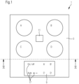
- an induction cooking hob 1 is schematically illustrated, indicating by circles four cooking zones A, B, C, D rectangularly arranged on a glass ceramic top panel 3. Each cooking zone A, B, C, D is heated by induction coils 5 arranged close to a bottom surface 7 of the top panel 3.
- the induction cooking hob 1 is further equipped with a user interface 9 positioned at the front edge of the induction cooking hob 1.
- the induction cooking hob 1further comprises an accelerometer 11, i. e. an acceleration sensor.
- Said accelerometer 11 is configured to determine and/or measure an acceleration, which may be a vibration or just an accelerated downwards movement, of the centre of the top panel 3 in vertical direction during or due to the impact of a manual or mechanical action onto the top side 13 of the top panel 3 or of a placement of a load like a cooking pot 15 filled with food.
- an acceleration which may be a vibration or just an accelerated downwards movement, of the centre of the top panel 3 in vertical direction during or due to the impact of a manual or mechanical action onto the top side 13 of the top panel 3 or of a placement of a load like a cooking pot 15 filled with food.
- the user interface 9 comprises a touch sensitive display adapted to receive user inputs for the operation of the cooking zones A, B, C, D and to display information, for example status information of the cooking zones A, B, C, D.
- the user can operate the cooking zones A, B, C, D through touch switches A', B', C', D', each one thereof assigned to one of the cooking zones A, B, C, D. Further touch switches 17 for other hob functions are covered as well.
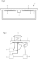
- Fig. 3 illustrates a detail view of one of the cooking zones A, B, C, D together with a schematic presentation of the wiring required for its operation.
- This illustration can also be seen as a basic configuration generally for an induction cooking hob 1 using the example of only one cooking zone A, B, C, D.
- Fig. 3 shows the section with the one cooking zone A, B, C, D, with the top panel 3 supporting a cooking pot 15 above the cooking zone A, B, C, D.
- the cooking zone A, B, C, D is exposed to electromagnetic waves emanated from the induction coil 5 located underneath the cooking zone A, B, C, D, the waves inducing eddy currents in the bottom of the cooking pot 15 with the effect of heating up said pot bottom.
- a thermal sensor 19 Located in the area of the cooking zone A, B, C, D is a thermal sensor 19, such as a thermostat, providing information about a temperature in this area.
- an induction generator 21 for magnetic waves is shown, which is connected to a controller 23, which controls the signals and the energy of the signals generated by the generator 21.
- a user interface controller 25 is also shown, which is connected to the controller 23 and to the accelerometer 11, which is a micro-electromechanical system (MEMS) in the present example.
- MEMS micro-electromechanical system
- the micro-electromechanical system 11 is attached to the induction cooking hob 1 indirectly via a dielectric shield 27, which may be made of a mica mineral substance being a hard substance, which does not substantially dampen vibrations and which protects the micro-electromechanical system 11 from electromagnetic waves emanated from the induction coil 5 or an electric field that builds up or is present during operation or at the induction cooking hob 1.
- a dielectric shield 27 may be made of a mica mineral substance being a hard substance, which does not substantially dampen vibrations and which protects the micro-electromechanical system 11 from electromagnetic waves emanated from the induction coil 5 or an electric field that builds up or is present during operation or at the induction cooking hob 1.
- mica also provides good thermal isolation against heat transmitted from e. g. a hot cooking pot 15 through the glass ceramic top panel 3.
- the above-described setup is used for the determination of the weight of the cooking pot 15 and specifically the weight of its content, particularly for weighing out newly added ingredients.
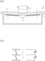
- the placing of the cooking pot 15 causes the top panel 3 of the induction cooking hob 1 to bend or deflect downwardly due to the weight of the cooking pot 15 (excessively shown for reasons of clarity).
- the magnitude of the bending or deflection is dependent on the weight value, so that the actual weight can be determined by measuring the said bending or deflection magnitude, which is a replicable process.
- Said bending or deflection measurement is performed by an integration over time of the acceleration or the accelerated movement of the reference area in the centre zone of the top panel 3 by means of the accelerometer 11, or the MEMS, respectively, which centre zone is also the position of fixation of the accelerometer 11 and is signalized on the top surface 13 of the top panel 3 as being the defined weighing area of the induction cooking hob 1.
- Fig. 5 illustrates schematically the structure of the MEMS acceleration sensor 11, which is of the type of a gravity sensor.
- the MEMS structure provides three piled plates 29a, 29b, 29c connected with each other by means of spiral springs 31.
- the upper and the lower plates 29c, 29a are fixed and the intermediate plate 29b is movable, but its movability is limited by the spiral springs 31.
- Such setup provides a series connection of two capacitors 33 with variable capacities because of a variable distance of the two plates 29a-29b, 29b-29c of a capacitor 33 following the movement of the intermediate plate 29b.
- the plates 29a, 29b, 29c are in an equidistant arrangement, but in the case of an accelerated movement of the acceleration sensor 11 the intermediate plate 29b is moved due to its moment of inertia.
- the occurring capacity changes are proportional to the acceleration and an integration of actual capacities allows the deduction of the covered deflection.
- FIG. 6 A second embodiment for the determination of the weight of a cooking pot 15 is shown in Fig. 6 .
- the structure of this embodiment is similar to the first one, which is readily understood when comparing it with Fig. 3 .
- the weight determination according to the second embodiment relies on the measurement of the magnitude of the displacement or deflection of the top panel 3 of the induction cooking hob 1 under the load of a cooking pot weight.
- said displacement or deflection is determined by means of an optical device comprising a photo sensor or photointerrupter 35.
- a photo sensor or photointerrupter 35 There are several types of such optical sensors known, usually operating with light emitting 37 and receiving 39 elements.
- the two basic types of photointerrupters 35 are the transmissive type (gap type) and the reflective type.
- the transmissive type is easier to operate because all optical elements 37, 39 are already adjusted.
- a signal is generated by interrupting light emitted from the light emitting element 37 on its way to the light receiving element 39 by an obstacle.
- the reflective type photointerrupter 35 needs a reflecting surface 41 for reflecting light emitted from the light emitting element 37. Since the light emitting and receiving elements 37, 39 facing the same direction, the distance of the reflecting surface 41 to the reflective type photointerrupter 35 is determined by the duration or transit time of emission and receipt of a light signal.
- a reflective type photointerrupter 35 is used.
- An example of this sensor type which is shown in Fig. 7 , is adapted to be mounted on a printed circuit board which may be fixed on an internal housing or compartment structure inside of the induction cooking hob 1, particularly on or at a carrier part for at least one induction coil 5 or on a protection box for the electronic components and circuit boards of the induction cooking hob 1.
- said fixation can be arbitrarily chosen, it just has to be ensured to choose a stationary position, uncoupled from the top panel 3.
- the photointerrupter 35 comprises a housing 43, said light emitting element 37, said light receiving element 39 and two ports 45 for each of said elements.
- an electronic unit on the printed circuit board and associated software the above-mentioned duration or transit time between emission and receipt of a light signal can be identified, which light signal is reflected from a reflecting surface 41 on the bottom surface 7 of the top panel 3, see Fig. 6 .
- the primary output of the photointerrupter 35 is an analogue signal, which is interpreted by said software.
- Said reflecting surface 41 on the bottom surface 7 of the top panel 3 may be applied by conventional printing on glass ceramic surface or by a drop of colour, particularly white colour. An application of a stencil on the glass surface is proposed for having a distance for thermal reasons.
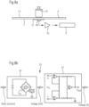
- Fig. 8a illustrates a third embodiment for weight determination of a cooking pot 15 by way of top panel displacement or deflection by showing an experimental arrangement.
- the weight load provided by a cooking pot 15 is simulated by a sample weight 47 placed on a glass ceramic top panel 3 as used in an induction cooking hob 1.
- the scale integrated in the induction cooking hob 1 comprises a strain gauge 49 attached to the bottom surface 7 of the top panel 3 by means of a glue 51. Due to this fixed attachment, the strain gauge 49 is following the bottom surface 7 in its extension, or elongation, respectively, which occurs when the top plate 3 is bent or deflected downwards.
- Said elongation exerted on the strain gauge 49 causes a resistance change which can be measured with applying a voltage thereon or, as a more reliable method, using an evaluation circuit 53 (see Fig. 8b ) comprising a Wheatstone bridge 55 and an instrumentation amplifier 57.
- Said evaluation circuit 53 works as follows: when the strain gauge 49 is put under stress (i.e. deflection causing an elongation), there is a resistance change in the strain gauge 49, which changes the voltage measurable at the Wheatstone resistance bridge 55. Said voltage is transferred to the instrumentation amplifier 57 as a voltage input V in , which voltage V in is amplified by the amplifier 57, in this respect improving readability and the accuracy of the measurement.
- intensity of resistance change in the strain gauge 49 and voltage output V out of the instrumentation amplifier 57 is proportional to the magnitude of strain gauge elongation and, hence, the top panel deflection. That way, weight of the cooking pot 15 can be determined with high accuracy.
- the Wheatstone bridge 55 is used for converting the strain resistance variation into voltage variation. But since the voltage output of the Wheatstone bridge 55 is typically too small for analysing said variation, an amplifier 57 for amplifying said voltage output may be necessary.
- the evaluation process for the selection of a suitable amplifier is dependent on a number of different parameters. In many situations the selection of an instrumentation amplifier 57 is convenient.
- the voltage output is transmitted to an evaluation circuit 53, particularly an electronic assembly within the user interface 9, which displays the weight of the cooking pot 15, for example on the user interface display, after conversion by means of a concordance list in a database of the induction cooking hob 1.
- a fourth embodiment for weight determination of a cooking pot 15 using an integrated scale in the induction cooking hob 1 is illustrated with Figs. 9 and 10 .
- the present example shown in Figs. 9 and 10 discloses a cover part 59 of a downdraft device or system, which is particularly a lid 59 of a downdraft exhaust system 61 implemented in a centre area of the cooking hob 1.
- the lid 59 is removable for a disassembly of a filter unit 63, as illustrated with Fig. 10 showing the disassembled lid 59 and the cylindrical filter cartridge 63.
- the downdraft exhaust system 61 is arranged in a cutout 65 in the centre area of the cooking hob 1.
- Said downdraft exhaust system 61 comprises a cylindrical exhaust compartment 67 including said cylindrical filter cartridge 63.
- the upper frame 69 which is arranged close to the circular cutout 65 in the top panel centre, of the cylindrical exhaust compartment 67 also forms a collar for supporting the lid 59 and provides a support for three weight sensors 71, which are arranged on the corners of an equilateral triangle. That way, the weight sensors 71 are squeezed between the lid 59 and the upper frame 69 of the exhaust compartment 67.
- the weight sensors 71 are preferably fixed to the upper frame 69 of the exhaust compartment 67, which allows them to be connected to the controller 23 or to the user interface 9 of the cooking hob 1 by wired connection. However, also coupling them to the lid 59 is possible, particularly when they are equipped with wireless communication means for a communication with the controller 23 or user interface 9.
Landscapes
- Engineering & Computer Science (AREA)
- General Physics & Mathematics (AREA)
- Physics & Mathematics (AREA)
- Mechanical Engineering (AREA)
- General Engineering & Computer Science (AREA)
- Chemical & Material Sciences (AREA)
- Combustion & Propulsion (AREA)
- Food Science & Technology (AREA)
- Manufacturing & Machinery (AREA)
- Cookers (AREA)
- Electric Stoves And Ranges (AREA)
- Induction Heating Cooking Devices (AREA)
- Investigating Strength Of Materials By Application Of Mechanical Stress (AREA)
- Bending Of Plates, Rods, And Pipes (AREA)
- Electric Ovens (AREA)
- Measurement Of The Respiration, Hearing Ability, Form, And Blood Characteristics Of Living Organisms (AREA)
Claims (21)
- Sensormittel oder Modul zum Bestimmen einer Verschiebung oder Biegung oder Beugung, insbesondere einer elastischen Verschiebung oder Biegung oder Beugung, einer Platte (3), insbesondere einer Glas- oder Glaskeramikplatte, oder eines Bereichs einer Platte (3) oder eines Einsatzes (59) in Bezug auf die Platte (3), wobei das Sensormittel (11, 35, 49, 71) oder das Modul und die Platte (3) oder der Bereich davon ein Wägemittel, insbesondere eine Waage, bildet, wobei das Sensormittel (11, 35, 49, 71) oder das Modul- angepasst ist, in ein Haushaltsgerät (1), insbesondere ein Kochfeld, noch weiter insbesondere ein Induktionskochfeld, integriert oder diesem zugewiesen zu werden, und- mindestens ein Verarbeitungs- und/oder Interpretations- und/oder Kompilationsmittel umfasst oder mit diesem verbunden ist,gekennzeichnet durch
einen Beschleunigungssensor (11) für eine Erfassung einer Beschleunigung des Plattenbereichs oder eines Plattenbezugspunkts oder einer Bezugsteilfläche, insbesondere eines Bezugspunkts oder einer Bezugsteilfläche auf einer Plattenoberfläche (7), während der elastischen Verschiebung oder Biegung oder Beugung des Plattenbereichs oder des Plattenbezugspunkts oder der Bezugsteilfläche aufgrund eines Platzierens eines zu wiegenden Gegenstands (15) auf der Platte (3). - Sensormittel oder Modul nach Anspruch 1,
gekennzeichnet durch
Berechnungsmittel für eine Schätzung der Verschiebung oder Biegung oder Beugung des Plattenbereichs oder des Plattenbezugspunkts oder der Plattenbezugsteilfläche durch Integration der Beschleunigung oder der beschleunigten Bewegung. - Sensormittel oder Modul nach Anspruch 1 oder 2,
gekennzeichnet durch
einen Fotosensor (35) zum Messen eines Abstands zu einer Oberfläche, insbesondere zu einem Bezugspunkt oder einer Bezugsteilfläche darauf, der Platte (3), wobei der Fotosensor (35) vorzugsweise unterhalb der Platte (3) positioniert ist und/oder ein Fotounterbrecher ist. - Sensormittel oder Modul nach Anspruch 3,
dadurch gekennzeichnet, dass
der Fotosensor (35) ein Fotosensor vom reflektierenden Typ ist und der Bezugspunkt oder die Bezugsteilfläche für die Abstandsmessung eine reflektierende Oberfläche (41) umfasst, wobei die reflektierende Oberfläche (41) vorzugsweise eine von- einer glänzenden Oberfläche, insbesondere einer metallisch glänzenden Oberfläche, der Platte,- einer bedruckten Glasoberfläche, insbesondere einer Oberfläche eines Metallbedampfungsglases,- einer Oberfläche eines Farbtropfens oder eines Aufdrucks, insbesondere eines weißen Farbtropfens, der auf die Oberfläche der Platte aufgebracht ist, ist. - Sensormittel oder Modul nach Anspruch 3 oder 4,
dadurch gekennzeichnet, dass
das Sensormittel (11, 35, 49, 71) oder Modul, insbesondere der Fotosensor (35), entfernt von der Platte (3), insbesondere an einem Gehäuse oder einem Rahmenteil des Haushaltsgeräts (1) oder eines im Inneren des Haushaltsgeräts (1) angeordneten Bauteils oder Moduls angeordnet ist oder angeordnet werden kann. - Sensormittel oder Modul nach einem der Ansprüche 3 bis 5,
dadurch gekennzeichnet, dass
der Fotosensor (35) auf einer Leiterplatte aufgebracht ist, die insbesondere mit dem Gehäuse oder dem Rahmenteil verbunden oder daran befestigt ist. - Sensormittel oder Modul nach Anspruch 1 und insbesondere nach einem der Ansprüche 2 bis 6,
gekennzeichnet durch- mindestens einen Dehnungsmessstreifen (49) und/oder Extensometer, der auf einer Bodenoberfläche (7) der Platte (3) platziert oder dieser zugewiesen ist und der angepasst ist, um den Wert einer Längenausdehnung der Bodenoberfläche (7) während der Biegung oder Beugung der Platte (3) nach unten zu bestimmen, und vorzugsweise durch- eine Wheatstonesche Messbrücke(55) zur Schätzung eines dem Dehnungsniveau oder dem Wert einer Längenausdehnung entsprechenden Dehnungswiderstands. - Sensormittel oder Modul nach Anspruch 7,
dadurch gekennzeichnet, dass
dem Sensormittel (11, 35, 49, 71) oder dem Modul, insbesondere dem Dehnungsmessstreifen (49) und/oder dem Extensometer und/oder der Wheatstoneschen Messbrücke (55), ein Verstärker (57) zugewiesen oder mit diesen verbunden ist. - Sensormittel oder Modul nach Anspruch 7 oder 8,
gekennzeichnet durch mindestens eines von- einer gezielt erhöhten Brückenspannung (Vin) der Wheatstoneschen Messbrücke (55), insbesondere einer Erregerspannung, die noch mehr insbesondere in einem Bereich von etwa 5 V bis etwa 12 V liegt;- einem gezielt erhöhten Dehnungsmessstreifen-Faktor des Dehnungsmessstreifens (49), wobei der Dehnungsmessstreifen-Faktor vorzugsweise größer als 2 ist und besonders bevorzugt in einem Bereich von etwa 5 bis etwa 16 liegt;- einem rauscharmen Verstärker und/oder einem Railto-Rail-Verstärker und/oder einem Instrumentenverstärker mit hoher Verstärkung (57). - Sensormittel oder Modul nach Anspruch 1 und insbesondere nach einem der Ansprüche 2 bis 9,
dadurch gekennzeichnet, dass
der Einsatz (59), der unter dem Gewicht eines zu wiegenden Gegenstands (15) in Bezug auf die Platte (3) verschoben oder bewegt wird, ein, vorzugsweise abnehmbares, Abdeckteil einer Downdraft-Vorrichtung oder eines Systems (61) in dem Haushaltsgerät (1) ist oder diesem zugewiesen ist, insbesondere ein Abdeckteil oder ein Deckel (59) eines Downdraft-Kochfelds. - Sensormittel oder Modul nach Anspruch 10,
dadurch gekennzeichnet, dass
das Sensormittel (11, 35, 49, 71) zwischen dem Abdeckteil (59) und einem Kragen (69) zum Abstützen des Abdeckteils (59) angeordnet ist, wobei der Kragen (69) an der Platte (3) angeordnet ist und einen oberen Rahmen eines Filterelements oder eines Filtereinlasses oder einer Filterkammer (67) bildet, wobei das Sensormittel (11, 35, 49, 71) vorzugsweise mit dem Abdeckteil (59) oder mit dem Kragen (69) gekoppelt ist. - Sensormittel oder Modul nach Anspruch 10,
dadurch gekennzeichnet, dass
das Sensormittel (11, 35, 49, 71) zwischen dem Abdeckteil (59) und einem Stützelement, vorzugsweise einem diametralen Stützbalken, angeordnet ist, der für das Sensormittel (11, 35, 49, 71) in einer mittigen Teilfläche, insbesondere auf einer Mittelachse angeordnet, der Downdraft-Vorrichtung oder des Systems (61) eine Abstützung bereitstellt. - Sensormittel oder Modul nach einem der Ansprüche 10 bis 12,
dadurch gekennzeichnet, dass
magnetische und/oder klebende Elemente oder sonstige Befestigungselemente oder Mittel für eine, vorzugsweise abnehmbare, Haftung des Abdeckteils (59) an der Platte (3), insbesondere am Kragen (69), und/oder des Sensormittels (11, 35, 49, 71) am Abdeckteil (59) oder am Kragen (69) oder Stützelement umfasst sind. - Sensormittel oder Modul nach einem der vorhergehenden Ansprüche, das Teil eines oder als Zusatzmodul für ein Haushaltsgerät (1) gebildet ist, zur Schätzung des Gewichts eines auf einer Oberfläche eines Haushaltsgeräts (1) platzierten Gegenstands (15), insbesondere eines auf einer oberen Oberfläche eines Kochfelds platzierten Kochgeschirrs.
- Sensormittel oder Modul nach Anspruch 14,
dadurch gekennzeichnet, dass
das Zusatzmodul umfasst- einen Berührungssensor oder eine Berührungssteuerungs-Benutzerschnittstelle, die angepasst ist, eine Benutzereingabe zu empfangen, und/oder- ein drahtloses Kommunikationsmittel, das so konfiguriert ist, dass es mit einer Steuereinheit des Haushaltsgeräts (1) verbunden werden kann. - Haushaltsgerät, insbesondere ein Kochfeld, noch weiter insbesondere ein Induktionskochfeld, umfassend eine mindestens annähernd horizontale Platte (3), insbesondere eine Glasplatte, wobei die Platte Teil einer Waage zum Wiegen eines auf der Platte (3) platzierten Gegenstands (15) ist oder mit dieser in funktionaler Verbindung steht, wobei das Haushaltsgerät (1) ferner ein Sensormittel (11, 35, 49, 71) oder ein Modul nach einem der vorhergehenden Ansprüche umfasst oder angepasst ist, mit diesem ausgestattet oder gekoppelt zu werden.
- Haushaltsgerät nach Anspruch 16,
dadurch gekennzeichnet, dass
eine Steuer- und/oder Verarbeitungseinheit mit dem Sensormittel (11, 35, 49, 71) oder dem Modul verbunden ist, um Daten aus dem Sensormittel (11, 35, 49, 71) oder dem Modul zu steuern und/oder abzurufen und/oder um ein Signal oder Daten aus dem Sensormittel (11, 35, 49, 71) oder dem Modul zu verarbeiten, wobei die Steuer- und/oder Verarbeitungseinheit (23) insbesondere eine Nachschlagetabelle und/oder eine Querverweisliste umfasst oder mit dieser verbunden ist, um mindestens annähernd eine mit dem bestimmten Verschiebungs- oder Biegungswert korrelierte Gewichtsangabe zu erhalten. - Haushaltsgerät nach Anspruch 16 oder 17,
dadurch gekennzeichnet, dass
das Sensormittel (11, 35, 49, 71) oder Modul in einer mittigen Zone der Platte (3), vorzugsweise in einer mittigen Zone einer oberen Platte eines Kochfeldes (1), angeordnet ist, wobei das Kochfeld (1) angepasst ist, um das Gewicht eines Kochgeschirrs (15) zu bestimmen, indem es auf die mittige Zone oder auf eine von mehreren Kochzonen (A, B, C, D) platziert wird. - Verfahren zum Bestimmen des Gewichts eines Gegenstands (15) auf einer mindestens annähernd horizontalen Platte (3) eines Haushaltsgeräts (1), insbesondere auf einer oberen Platte eines Kochfelds,
dadurch gekennzeichnet, dass
eine Beschleunigung eines Plattenbereichs oder eines Plattenbezugspunkts oder einer Bezugsteilfläche, insbesondere eines Bezugspunkts oder einer Bezugsteilfläche auf einer Plattenoberfläche (7), während einer Verschiebung oder Biegung oder Beugung des Plattenbereichs oder des Plattenbezugspunkts oder der Bezugsteilfläche aufgrund eines Platzierens des Gegenstands (15) auf der Platte (3) geschätzt oder bestimmt wird, wobei die Schätzung oder Bestimmung des Gewichts insbesondere durch das Platzieren des Gegenstands (15) auf der Platte oder durch eine Benutzereingabe ausgelöst wird. - Verfahren nach Anspruch 19,
dadurch gekennzeichnet, dass
die Verschiebung oder Biegung oder Beugung durch eine Integration über die Zeit der Beschleunigung oder der beschleunigten Bewegung geschätzt oder bestimmt wird. - Verfahren nach Anspruch 19 oder 20,
dadurch gekennzeichnet, dass
die geschätzte oder bestimmte Gewichtsangabe auf einer Anzeigeeinrichtung, insbesondere einer Benutzerschnittstelle (9) des Haushaltsgeräts (1) oder des Sensormittels (11, 35, 49, 71) oder des Moduls, angezeigt oder während eines im Haushaltsgerät (1) ablaufenden Betriebsprozesses, insbesondere während eines Kochvorgangs auf einem Kochfeld, verarbeitet wird.
Applications Claiming Priority (2)
| Application Number | Priority Date | Filing Date | Title |
|---|---|---|---|
| EP20167868.7A EP3889558B1 (de) | 2020-04-03 | 2020-04-03 | Ein sensormittel oder -modul zur bestimmung einer verschiebung, insbesondere einer elastischen verschiebung, eines einsatzes in bezug auf eine platte |
| PCT/EP2021/056763 WO2021197844A1 (en) | 2020-04-03 | 2021-03-17 | Sensor means or module for determining a displacement or deflection or bending, household appliance and method for determining the weight of an item |
Publications (2)
| Publication Number | Publication Date |
|---|---|
| EP4127619A1 EP4127619A1 (de) | 2023-02-08 |
| EP4127619B1 true EP4127619B1 (de) | 2024-10-09 |
Family
ID=70165912
Family Applications (2)
| Application Number | Title | Priority Date | Filing Date |
|---|---|---|---|
| EP20167868.7A Active EP3889558B1 (de) | 2020-04-03 | 2020-04-03 | Ein sensormittel oder -modul zur bestimmung einer verschiebung, insbesondere einer elastischen verschiebung, eines einsatzes in bezug auf eine platte |
| EP21712494.0A Active EP4127619B1 (de) | 2020-04-03 | 2021-03-17 | Sensormittel oder modul zur bestimmung einer verschiebung, durchbiegung oder biegung, haushaltsgerät und verfahren zur bestimmung des gewichts eines gegenstandes |
Family Applications Before (1)
| Application Number | Title | Priority Date | Filing Date |
|---|---|---|---|
| EP20167868.7A Active EP3889558B1 (de) | 2020-04-03 | 2020-04-03 | Ein sensormittel oder -modul zur bestimmung einer verschiebung, insbesondere einer elastischen verschiebung, eines einsatzes in bezug auf eine platte |
Country Status (6)
| Country | Link |
|---|---|
| EP (2) | EP3889558B1 (de) |
| CN (1) | CN115362353B (de) |
| AU (1) | AU2021248456B2 (de) |
| BR (1) | BR112022019502A2 (de) |
| ES (1) | ES2976637T3 (de) |
| WO (1) | WO2021197844A1 (de) |
Family Cites Families (21)
| Publication number | Priority date | Publication date | Assignee | Title |
|---|---|---|---|---|
| CN2173229Y (zh) * | 1993-10-11 | 1994-08-03 | 冶金工业部钢铁研究总院 | 动态称量吊钩秤 |
| DE9410156U1 (de) * | 1994-06-17 | 1994-09-22 | Createc Patent Holding S.A., Luxembourg | Küchenwaage |
| DE19612621C2 (de) * | 1996-03-29 | 1999-03-11 | Schott Glas | Kochfeld mit einer Kochfläche aus Glas oder Glaskeramik |
| DE19926513A1 (de) | 1999-06-10 | 2000-12-21 | Bsh Bosch Siemens Hausgeraete | Kochfeld mit Wägeeinheit |
| DE10139388A1 (de) * | 2001-08-10 | 2003-02-27 | Bsh Bosch Siemens Hausgeraete | Wäschebehandlungsgerät mit Unwuchtüberwachung, mit Erkennung des Niveaus oder mit Erkennung der Beladung |
| JP4416460B2 (ja) * | 2003-09-16 | 2010-02-17 | トレックス・セミコンダクター株式会社 | 加速度センサー |
| US8872077B2 (en) * | 2005-08-01 | 2014-10-28 | Western Industries, Inc. | Low profile induction cook top with heat management system |
| DE102006004381A1 (de) * | 2006-01-31 | 2007-08-02 | BSH Bosch und Siemens Hausgeräte GmbH | Gargerät, insbesondere Hocheinbau-Gargerät, und Verfahren zum Steuern eines Gargeräts |
| TWI404521B (zh) * | 2010-01-20 | 2013-08-11 | Univ Yuan Ze | Body balance signal measurement system and its analysis method |
| EP2999301B1 (de) * | 2014-09-18 | 2019-03-06 | Electrolux Appliances Aktiebolag | Induktionskochfeld mit Siededetektion und Induktionsenergiesteuerung, Verfahren zum Erwärmen von Speisen mit einem Induktionskochfeld und Computerprogrammprodukt |
| US20190234617A1 (en) * | 2015-05-05 | 2019-08-01 | June Life, Inc. | Connected food preparation system and method of use |
| EP3172996B1 (de) * | 2015-11-30 | 2021-01-13 | Whirlpool Corporation | Kochsystem |
| US20190095024A1 (en) * | 2016-02-04 | 2019-03-28 | Shenzhen New Degree Technology Co., Ltd. | Pressure sensing device and electronic apparatus having same |
| DE102016211207B4 (de) * | 2016-06-22 | 2025-03-13 | Werkhaus GmbH & Co. KG | Vorrichtung zum Abzug von Kochdünsten |
| DE102016114822B3 (de) * | 2016-08-10 | 2017-10-12 | Miele & Cie. Kg | Kochfeld, insbesondere Induktionskochfeld |
| CN106594808A (zh) * | 2016-11-09 | 2017-04-26 | 浙江优格厨电有限公司 | 蒸烤一体侧吸式集成灶及其运作方法 |
| KR101803503B1 (ko) * | 2017-02-06 | 2017-11-30 | 주식회사 풍산에프앤에스 | 구조물의 정밀 계측 시스템 및 그 방법 |
| KR101880865B1 (ko) * | 2017-12-04 | 2018-07-20 | 최은성 | 자동으로 회전하며 요리되는 통돌이 오븐 방식의 가스오븐 조리기 |
| IT201800000794A1 (it) * | 2018-01-12 | 2019-07-12 | Elica Spa | Piano cottura con cappa aspirante e bilancia integrate |
| CN108954405B (zh) * | 2018-06-27 | 2022-12-20 | 青岛海尔智能技术研发有限公司 | 防干烧灶具 |
| CN209899148U (zh) * | 2019-04-25 | 2020-01-07 | 深圳市豫龙电测技术有限公司 | 一种具有称重功能的家用电器 |
-
2020
- 2020-04-03 EP EP20167868.7A patent/EP3889558B1/de active Active
- 2020-04-03 ES ES20167868T patent/ES2976637T3/es active Active
-
2021
- 2021-03-17 WO PCT/EP2021/056763 patent/WO2021197844A1/en not_active Ceased
- 2021-03-17 EP EP21712494.0A patent/EP4127619B1/de active Active
- 2021-03-17 AU AU2021248456A patent/AU2021248456B2/en active Active
- 2021-03-17 CN CN202180025962.0A patent/CN115362353B/zh active Active
- 2021-03-17 BR BR112022019502A patent/BR112022019502A2/pt unknown
Also Published As
| Publication number | Publication date |
|---|---|
| EP4127619A1 (de) | 2023-02-08 |
| AU2021248456B2 (en) | 2025-09-04 |
| EP3889558B1 (de) | 2024-01-24 |
| US20230137254A1 (en) | 2023-05-04 |
| AU2021248456A1 (en) | 2022-09-08 |
| WO2021197844A1 (en) | 2021-10-07 |
| BR112022019502A2 (pt) | 2022-11-16 |
| EP3889558A1 (de) | 2021-10-06 |
| ES2976637T3 (es) | 2024-08-06 |
| CN115362353B (zh) | 2026-01-02 |
| CN115362353A (zh) | 2022-11-18 |
Similar Documents
| Publication | Publication Date | Title |
|---|---|---|
| EP2999301B1 (de) | Induktionskochfeld mit Siededetektion und Induktionsenergiesteuerung, Verfahren zum Erwärmen von Speisen mit einem Induktionskochfeld und Computerprogrammprodukt | |
| EP2180760B1 (de) | Verfahren zur Erkennung der Präsenz eines Kochkessels auf einem Induktionsherd und Herd zur Nutzung eines solchen Verfahrens | |
| CN108692808B (zh) | 一种测振式识别锅内液体状态的方法和装置 | |
| US20230094391A1 (en) | Household appliance with acceleration detection and/or measuring means and control unit and method for controlling a household appliance | |
| EP4127619B1 (de) | Sensormittel oder modul zur bestimmung einer verschiebung, durchbiegung oder biegung, haushaltsgerät und verfahren zur bestimmung des gewichts eines gegenstandes | |
| US12613125B2 (en) | Sensor means or module for determining a displacement or deflection or bending, household appliance and method for determining the weight of an item | |
| US5349138A (en) | Food weight sensing device for microwave oven | |
| CA1236887A (en) | Heating apparatus having a weight detector | |
| US6600140B2 (en) | Configuration with a cooker and cooktop with an integrated weighting function | |
| JPS6217530A (ja) | 重量検出機能付加熱調理器 | |
| JP2010112599A (ja) | 加熱調理器 | |
| CN108954402B (zh) | 防干烧灶具 | |
| JP2005009771A (ja) | 加熱調理器とそれに用いた静電容量式重量センサ | |
| JPS6321419A (ja) | 重量センサ−付ガスコンロ | |
| JP2000018596A (ja) | 調理器 | |
| JP4206957B2 (ja) | 炊飯器 | |
| JPS61283835A (ja) | 重量検出機構 | |
| JPS5864429A (ja) | 加熱調理器 | |
| JP2004248804A (ja) | 炊飯器 | |
| JPH0575248B2 (de) | ||
| JPS6316012B2 (de) | ||
| JPH0228051B2 (ja) | Hakarikinoojusurukanetsuchoriki | |
| JPH02305516A (ja) | 調理器用重量検出装置 | |
| JPH0519803U (ja) | 高周波加熱装置 | |
| JPH02305514A (ja) | 調理器用重量検出装置 |
Legal Events
| Date | Code | Title | Description |
|---|---|---|---|
| STAA | Information on the status of an ep patent application or granted ep patent |
Free format text: STATUS: UNKNOWN |
|
| STAA | Information on the status of an ep patent application or granted ep patent |
Free format text: STATUS: THE INTERNATIONAL PUBLICATION HAS BEEN MADE |
|
| PUAI | Public reference made under article 153(3) epc to a published international application that has entered the european phase |
Free format text: ORIGINAL CODE: 0009012 |
|
| STAA | Information on the status of an ep patent application or granted ep patent |
Free format text: STATUS: REQUEST FOR EXAMINATION WAS MADE |
|
| 17P | Request for examination filed |
Effective date: 20221103 |
|
| AK | Designated contracting states |
Kind code of ref document: A1 Designated state(s): AL AT BE BG CH CY CZ DE DK EE ES FI FR GB GR HR HU IE IS IT LI LT LU LV MC MK MT NL NO PL PT RO RS SE SI SK SM TR |
|
| DAV | Request for validation of the european patent (deleted) | ||
| DAX | Request for extension of the european patent (deleted) | ||
| GRAP | Despatch of communication of intention to grant a patent |
Free format text: ORIGINAL CODE: EPIDOSNIGR1 |
|
| STAA | Information on the status of an ep patent application or granted ep patent |
Free format text: STATUS: GRANT OF PATENT IS INTENDED |
|
| INTG | Intention to grant announced |
Effective date: 20240513 |
|
| P01 | Opt-out of the competence of the unified patent court (upc) registered |
Free format text: CASE NUMBER: APP_36550/2024 Effective date: 20240619 |
|
| GRAS | Grant fee paid |
Free format text: ORIGINAL CODE: EPIDOSNIGR3 |
|
| GRAA | (expected) grant |
Free format text: ORIGINAL CODE: 0009210 |
|
| STAA | Information on the status of an ep patent application or granted ep patent |
Free format text: STATUS: THE PATENT HAS BEEN GRANTED |
|
| AK | Designated contracting states |
Kind code of ref document: B1 Designated state(s): AL AT BE BG CH CY CZ DE DK EE ES FI FR GB GR HR HU IE IS IT LI LT LU LV MC MK MT NL NO PL PT RO RS SE SI SK SM TR |
|
| REG | Reference to a national code |
Ref country code: CH Ref legal event code: EP |
|
| REG | Reference to a national code |
Ref country code: DE Ref legal event code: R096 Ref document number: 602021019933 Country of ref document: DE |
|
| REG | Reference to a national code |
Ref country code: IE Ref legal event code: FG4D |
|
| REG | Reference to a national code |
Ref country code: LT Ref legal event code: MG9D |
|
| REG | Reference to a national code |
Ref country code: NL Ref legal event code: MP Effective date: 20241009 |
|
| REG | Reference to a national code |
Ref country code: AT Ref legal event code: MK05 Ref document number: 1731027 Country of ref document: AT Kind code of ref document: T Effective date: 20241009 |
|
| PG25 | Lapsed in a contracting state [announced via postgrant information from national office to epo] |
Ref country code: NL Free format text: LAPSE BECAUSE OF FAILURE TO SUBMIT A TRANSLATION OF THE DESCRIPTION OR TO PAY THE FEE WITHIN THE PRESCRIBED TIME-LIMIT Effective date: 20241009 |
|
| PG25 | Lapsed in a contracting state [announced via postgrant information from national office to epo] |
Ref country code: NL Free format text: LAPSE BECAUSE OF FAILURE TO SUBMIT A TRANSLATION OF THE DESCRIPTION OR TO PAY THE FEE WITHIN THE PRESCRIBED TIME-LIMIT Effective date: 20241009 |
|
| PG25 | Lapsed in a contracting state [announced via postgrant information from national office to epo] |
Ref country code: HR Free format text: LAPSE BECAUSE OF FAILURE TO SUBMIT A TRANSLATION OF THE DESCRIPTION OR TO PAY THE FEE WITHIN THE PRESCRIBED TIME-LIMIT Effective date: 20241009 Ref country code: PT Free format text: LAPSE BECAUSE OF FAILURE TO SUBMIT A TRANSLATION OF THE DESCRIPTION OR TO PAY THE FEE WITHIN THE PRESCRIBED TIME-LIMIT Effective date: 20250210 Ref country code: IS Free format text: LAPSE BECAUSE OF FAILURE TO SUBMIT A TRANSLATION OF THE DESCRIPTION OR TO PAY THE FEE WITHIN THE PRESCRIBED TIME-LIMIT Effective date: 20250209 |
|
| PG25 | Lapsed in a contracting state [announced via postgrant information from national office to epo] |
Ref country code: FI Free format text: LAPSE BECAUSE OF FAILURE TO SUBMIT A TRANSLATION OF THE DESCRIPTION OR TO PAY THE FEE WITHIN THE PRESCRIBED TIME-LIMIT Effective date: 20241009 |
|
| PG25 | Lapsed in a contracting state [announced via postgrant information from national office to epo] |
Ref country code: BG Free format text: LAPSE BECAUSE OF FAILURE TO SUBMIT A TRANSLATION OF THE DESCRIPTION OR TO PAY THE FEE WITHIN THE PRESCRIBED TIME-LIMIT Effective date: 20241009 |
|
| PG25 | Lapsed in a contracting state [announced via postgrant information from national office to epo] |
Ref country code: ES Free format text: LAPSE BECAUSE OF FAILURE TO SUBMIT A TRANSLATION OF THE DESCRIPTION OR TO PAY THE FEE WITHIN THE PRESCRIBED TIME-LIMIT Effective date: 20241009 |
|
| PG25 | Lapsed in a contracting state [announced via postgrant information from national office to epo] |
Ref country code: NO Free format text: LAPSE BECAUSE OF FAILURE TO SUBMIT A TRANSLATION OF THE DESCRIPTION OR TO PAY THE FEE WITHIN THE PRESCRIBED TIME-LIMIT Effective date: 20250109 |
|
| PG25 | Lapsed in a contracting state [announced via postgrant information from national office to epo] |
Ref country code: LV Free format text: LAPSE BECAUSE OF FAILURE TO SUBMIT A TRANSLATION OF THE DESCRIPTION OR TO PAY THE FEE WITHIN THE PRESCRIBED TIME-LIMIT Effective date: 20241009 Ref country code: GR Free format text: LAPSE BECAUSE OF FAILURE TO SUBMIT A TRANSLATION OF THE DESCRIPTION OR TO PAY THE FEE WITHIN THE PRESCRIBED TIME-LIMIT Effective date: 20250110 Ref country code: AT Free format text: LAPSE BECAUSE OF FAILURE TO SUBMIT A TRANSLATION OF THE DESCRIPTION OR TO PAY THE FEE WITHIN THE PRESCRIBED TIME-LIMIT Effective date: 20241009 |
|
| PG25 | Lapsed in a contracting state [announced via postgrant information from national office to epo] |
Ref country code: PL Free format text: LAPSE BECAUSE OF FAILURE TO SUBMIT A TRANSLATION OF THE DESCRIPTION OR TO PAY THE FEE WITHIN THE PRESCRIBED TIME-LIMIT Effective date: 20241009 |
|
| PG25 | Lapsed in a contracting state [announced via postgrant information from national office to epo] |
Ref country code: RS Free format text: LAPSE BECAUSE OF FAILURE TO SUBMIT A TRANSLATION OF THE DESCRIPTION OR TO PAY THE FEE WITHIN THE PRESCRIBED TIME-LIMIT Effective date: 20250109 |
|
| PG25 | Lapsed in a contracting state [announced via postgrant information from national office to epo] |
Ref country code: SM Free format text: LAPSE BECAUSE OF FAILURE TO SUBMIT A TRANSLATION OF THE DESCRIPTION OR TO PAY THE FEE WITHIN THE PRESCRIBED TIME-LIMIT Effective date: 20241009 |
|
| PG25 | Lapsed in a contracting state [announced via postgrant information from national office to epo] |
Ref country code: DK Free format text: LAPSE BECAUSE OF FAILURE TO SUBMIT A TRANSLATION OF THE DESCRIPTION OR TO PAY THE FEE WITHIN THE PRESCRIBED TIME-LIMIT Effective date: 20241009 |
|
| REG | Reference to a national code |
Ref country code: DE Ref legal event code: R097 Ref document number: 602021019933 Country of ref document: DE |
|
| PG25 | Lapsed in a contracting state [announced via postgrant information from national office to epo] |
Ref country code: EE Free format text: LAPSE BECAUSE OF FAILURE TO SUBMIT A TRANSLATION OF THE DESCRIPTION OR TO PAY THE FEE WITHIN THE PRESCRIBED TIME-LIMIT Effective date: 20241009 |
|
| PG25 | Lapsed in a contracting state [announced via postgrant information from national office to epo] |
Ref country code: RO Free format text: LAPSE BECAUSE OF FAILURE TO SUBMIT A TRANSLATION OF THE DESCRIPTION OR TO PAY THE FEE WITHIN THE PRESCRIBED TIME-LIMIT Effective date: 20241009 |
|
| PG25 | Lapsed in a contracting state [announced via postgrant information from national office to epo] |
Ref country code: SK Free format text: LAPSE BECAUSE OF FAILURE TO SUBMIT A TRANSLATION OF THE DESCRIPTION OR TO PAY THE FEE WITHIN THE PRESCRIBED TIME-LIMIT Effective date: 20241009 |
|
| PG25 | Lapsed in a contracting state [announced via postgrant information from national office to epo] |
Ref country code: CZ Free format text: LAPSE BECAUSE OF FAILURE TO SUBMIT A TRANSLATION OF THE DESCRIPTION OR TO PAY THE FEE WITHIN THE PRESCRIBED TIME-LIMIT Effective date: 20241009 |
|
| PLBE | No opposition filed within time limit |
Free format text: ORIGINAL CODE: 0009261 |
|
| STAA | Information on the status of an ep patent application or granted ep patent |
Free format text: STATUS: NO OPPOSITION FILED WITHIN TIME LIMIT |
|
| PG25 | Lapsed in a contracting state [announced via postgrant information from national office to epo] |
Ref country code: SE Free format text: LAPSE BECAUSE OF FAILURE TO SUBMIT A TRANSLATION OF THE DESCRIPTION OR TO PAY THE FEE WITHIN THE PRESCRIBED TIME-LIMIT Effective date: 20241009 |
|
| 26N | No opposition filed |
Effective date: 20250710 |
|
| PG25 | Lapsed in a contracting state [announced via postgrant information from national office to epo] |
Ref country code: MC Free format text: LAPSE BECAUSE OF FAILURE TO SUBMIT A TRANSLATION OF THE DESCRIPTION OR TO PAY THE FEE WITHIN THE PRESCRIBED TIME-LIMIT Effective date: 20241009 |
|
| REG | Reference to a national code |
Ref country code: CH Ref legal event code: H13 Free format text: ST27 STATUS EVENT CODE: U-0-0-H10-H13 (AS PROVIDED BY THE NATIONAL OFFICE) Effective date: 20251023 |
|
| PG25 | Lapsed in a contracting state [announced via postgrant information from national office to epo] |
Ref country code: LU Free format text: LAPSE BECAUSE OF NON-PAYMENT OF DUE FEES Effective date: 20250317 |
|
| GBPC | Gb: european patent ceased through non-payment of renewal fee |
Effective date: 20250317 |
|
| REG | Reference to a national code |
Ref country code: BE Ref legal event code: MM Effective date: 20250331 |
|
| PG25 | Lapsed in a contracting state [announced via postgrant information from national office to epo] |
Ref country code: GB Free format text: LAPSE BECAUSE OF NON-PAYMENT OF DUE FEES Effective date: 20250317 |
|
| PG25 | Lapsed in a contracting state [announced via postgrant information from national office to epo] |
Ref country code: BE Free format text: LAPSE BECAUSE OF NON-PAYMENT OF DUE FEES Effective date: 20250331 |
|
| PG25 | Lapsed in a contracting state [announced via postgrant information from national office to epo] |
Ref country code: CH Free format text: LAPSE BECAUSE OF NON-PAYMENT OF DUE FEES Effective date: 20250331 |
|
| PG25 | Lapsed in a contracting state [announced via postgrant information from national office to epo] |
Ref country code: IE Free format text: LAPSE BECAUSE OF NON-PAYMENT OF DUE FEES Effective date: 20250317 |
|
| PGFP | Annual fee paid to national office [announced via postgrant information from national office to epo] |
Ref country code: DE Payment date: 20260320 Year of fee payment: 6 |
|
| PGFP | Annual fee paid to national office [announced via postgrant information from national office to epo] |
Ref country code: IT Payment date: 20260320 Year of fee payment: 6 |
|
| PGFP | Annual fee paid to national office [announced via postgrant information from national office to epo] |
Ref country code: FR Payment date: 20260323 Year of fee payment: 6 |