EP4124700B1 - Terrassendach - Google Patents
Terrassendach Download PDFInfo
- Publication number
- EP4124700B1 EP4124700B1 EP22187627.9A EP22187627A EP4124700B1 EP 4124700 B1 EP4124700 B1 EP 4124700B1 EP 22187627 A EP22187627 A EP 22187627A EP 4124700 B1 EP4124700 B1 EP 4124700B1
- Authority
- EP
- European Patent Office
- Prior art keywords
- terrace
- hinge
- coupling piece
- side guide
- canopy according
- Prior art date
- Legal status (The legal status is an assumption and is not a legal conclusion. Google has not performed a legal analysis and makes no representation as to the accuracy of the status listed.)
- Active
Links
Images


Classifications
-
- E—FIXED CONSTRUCTIONS
- E04—BUILDING
- E04F—FINISHING WORK ON BUILDINGS, e.g. STAIRS, FLOORS
- E04F10/00—Sunshades, e.g. Florentine blinds or jalousies; Outside screens; Awnings or baldachins
- E04F10/02—Sunshades, e.g. Florentine blinds or jalousies; Outside screens; Awnings or baldachins of flexible canopy materials, e.g. canvas ; Baldachins
- E04F10/06—Sunshades, e.g. Florentine blinds or jalousies; Outside screens; Awnings or baldachins of flexible canopy materials, e.g. canvas ; Baldachins comprising a roller-blind with means for holding the end away from a building
- E04F10/0607—Sunshades, e.g. Florentine blinds or jalousies; Outside screens; Awnings or baldachins of flexible canopy materials, e.g. canvas ; Baldachins comprising a roller-blind with means for holding the end away from a building with guiding-sections for supporting the movable end of the blind
-
- E—FIXED CONSTRUCTIONS
- E04—BUILDING
- E04F—FINISHING WORK ON BUILDINGS, e.g. STAIRS, FLOORS
- E04F10/00—Sunshades, e.g. Florentine blinds or jalousies; Outside screens; Awnings or baldachins
- E04F10/02—Sunshades, e.g. Florentine blinds or jalousies; Outside screens; Awnings or baldachins of flexible canopy materials, e.g. canvas ; Baldachins
- E04F10/06—Sunshades, e.g. Florentine blinds or jalousies; Outside screens; Awnings or baldachins of flexible canopy materials, e.g. canvas ; Baldachins comprising a roller-blind with means for holding the end away from a building
- E04F10/0637—Sunshades, e.g. Florentine blinds or jalousies; Outside screens; Awnings or baldachins of flexible canopy materials, e.g. canvas ; Baldachins comprising a roller-blind with means for holding the end away from a building with mechanisms for adjusting the inclination of the blind
-
- E—FIXED CONSTRUCTIONS
- E04—BUILDING
- E04F—FINISHING WORK ON BUILDINGS, e.g. STAIRS, FLOORS
- E04F10/00—Sunshades, e.g. Florentine blinds or jalousies; Outside screens; Awnings or baldachins
- E04F10/02—Sunshades, e.g. Florentine blinds or jalousies; Outside screens; Awnings or baldachins of flexible canopy materials, e.g. canvas ; Baldachins
- E04F10/06—Sunshades, e.g. Florentine blinds or jalousies; Outside screens; Awnings or baldachins of flexible canopy materials, e.g. canvas ; Baldachins comprising a roller-blind with means for holding the end away from a building
- E04F10/0666—Accessories
- E04F10/0681—Support posts for the movable end of the blind
Definitions
- the present invention relates to a terrace canopy.
- the invention is intended for a screen awning which is used as terrace canopy or pergola.
- the screen awning contains a screen, for example in the form of a tarpaulin, which is retractable and extendable on a shaft from a roller casing which is mounted on a façade or the like at a certain height.
- the screen On its side edges, the screen is guided in two parallel side guide rails which depart from the roller casing and run diagonally downward to give the screen a certain slope when retracting and extending.
- each side guide rail is supported by a support post.
- the screen awning is mounted to the façade and needs a minimum screen slope.
- the drop and screen slope depends on the mounting height to the façade and the available distance to the façade for mounting the support posts.
- the mounting height of the roller casing is also determined by the straightness of the wall, distribution of the bores for mounting and where drilling is possible, etc.
- the roller casing needs to be able to tilt more or less around its longitudinal axis and the coupling of the side guide rails with the front support post must at least be rotatable around a horizontal shaft which extends perpendicularly to the longitudinal direction of the side guide rails and/or the height of the coupling must be adjustable.
- Another embodiment is known from EP 2.333.188 whereby the guide rails are supported at their lower end with a coupling piece in a gutter composed of a gutter profiled section with a channel for the lateral guidance and a tilting movement of the coupling piece, whereby the coupling piece is also provided with limited guidance in the longitudinal direction of the tarpaulin guide rails.
- This embodiment is relatively complex and difficult to mount and adjust and does not allow the guide rails and the tarpaulin to protrude forward beyond the gutter.
- the awning comprises at least one shading element, the front end of which is attached to an extension profile, the extension profile being guided on guide rails so that it can be moved in the extension direction and in the extension direction front ends of the guide rails are supported by supports, at least one support being variable in length and the connection between a support and that of this support carried guide rail is formed by an articulated connection between the guide rail and the support, the articulated connection allowing the guide rail to pivot relative to the support about an articulated axis parallel to the extension profile and the articulated parts of the articulated connection can be disengaged parallel to the articulated axis.
- the terrace canopy comprises a fabric shaft that can be mounted on a holding structure, an awning fabric that can be wound on it, a drop profile at the front end of the awning fabric, on both sides parallel to the dropout direction (A) of the awning fabric arranged guide rails for the dropout profile, and support columns at the ends of the guide rails facing away from the holding structure, wherein at least one of the support columns for one-sided lowering of the awning fabric is variable in height.
- the purpose of the present invention is to provide a solution for one or more of the aforementioned and other disadvantages with an all-in-one solution with a coupling piece that ensures attachment and strengthening, allowing finetuning of at least the height and translation of the lower end of the side guide rails relative to the support post, whereby all controls are easily accessible and are all grouped close together in one location and ultimately are practically invisible from the outside.
- the invention relates to a terrace canopy according to claim 1.
- the coupling piece is hidden from view for bystanders or people under the terrace canopy.
- the hinge mounted on the side guide rail is movable in the longitudinal direction of the side guide rail.
- the hollow support posts are composed of an open basic profile with two or three legs perpendicular to each other which define an open space and of a removable cover profile which covers the aforementioned space in the longitudinal direction of the basic profile.
- the coupling piece is easily accessible after disassembly of the cover profile for an easy adjustment of the position of the coupling piece and thus of the slope of the relevant side guide rail.
- the coupling piece is executed as a strengthening bracket which connects at least two legs of the basic profile with each other and is height adjustably mounted on the inside of the basic profile.
- the coupling piece also has the role of strengthening the base piece of the support post such that such support post can be used as single support post without the profile of the support post, typically from aluminium, having to be executed extra heavy.
- the coupling piece contains a substantially L-shaped or U-shaped section with which the coupling piece is mounted against the inside of the basic profile of the support post.
- Such L-shaped or U-shaped section can easily be realised in steel plate.
- the coupling piece can be provided with a transverse strengthening which connects at least two legs of the L-shaped or U-shaped section with each other.
- the basic profile is provided with one or more undercut mounting grooves lengthways and the coupling piece is translationally mounted on the basic profile by means of nuts which are translationally mounted in the grooves and screwed tight in the nuts by means of bolts through bores in the coupling piece for clamping the coupling piece.
- the basic profile is provided with a stop to limit the upward translation of the coupling piece, said stop being mounted such that the coupling piece cannot protrude above the upper end of the support post.
- the coupling piece contains a support, for example in the form of a transverse support plate which is provided with at least one slotted hole that extends parallel to a plane perpendicular to the shaft of the hinge and the hinge foot is translationally mounted on the support by means of one or more bolts screwed through the at least one slotted hole in the hinge nut for clamping the hinge foot to the support.
- a support for example in the form of a transverse support plate which is provided with at least one slotted hole that extends parallel to a plane perpendicular to the shaft of the hinge and the hinge foot is translationally mounted on the support by means of one or more bolts screwed through the at least one slotted hole in the hinge nut for clamping the hinge foot to the support.
- the hinge parts of the aforementioned hinge seen in a cross-section perpendicular to the shaft of the hinge, are shaped substantially triangularly and the tips overlap each other at a certain height.
- the hinge parts have a sufficient range of movement to not collide with the walls of the support post when setting the slope of the side guide rail.
- the terrace canopy can be provided with a front bar with which the support posts are mutually connected and/or with one or more substantially horizontal side bars for the connection between a support post and a wall or other support posts to which the roller casing is mounted.
- said bars can also serve as roller casing for the integration of a roller and a retractable and extendable screen thereon, for example to be able to shield the terrace at the front and/or sides from wind and sun.
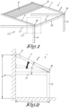
- the terrace canopy 1 shown in figures 1 to 7 contains a roof structure 2 containing a roller casing 3 which is mounted against a façade 4 or other bearing structure at a certain height and contains a roll with a retractable and extendable screen 5, for example a tarpaulin, which on the lower edge is provided with a bottom bar 6 which when retracting and extending is guided in two parallel sloping side guide rails 7 which are supported on their lower extremity 8 by two support posts 9 located at a distance from the façade 4.
- a retractable and extendable screen 5 for example a tarpaulin
- the support posts 9 are hollow support posts which in the example are mutually connected by means of a front bar 10 and are connected to the façade 4 by means of side bars 11 which extend substantially horizontally under the side guide rails 7.
- the roller casing 3 is mounted against the façade 4 by means of a suspension (not shown) with which the roller casing 3 is tiltable around its longitudinal axis to, upon mounting, set the slope of the side guide rails 7 and thus of the screen 5 depending on the local circumstances such as, among others, the available mounting height B against the façade 4 and the available distance C to the façade 4 for mounting the support posts 9.
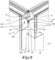
- the invention provides a coupling piece 12 which is mounted in the hollow support posts 9 and is provided with a hinge 13 with a horizontal shaft 13c which is transversely oriented according to the transversal direction X-X' relative to the longitudinal direction Q-Q' of the side guide rails 7.
- the hollow support posts 9 are composed of an L-shaped open basic profile 14 with two legs 14a and 14b perpendicular to each other which define an open space 15 and of a removable L-shaped cover profile 16 that covers the aforementioned space 15 over the height of the basic profile 14 and which is snapped on the basic profile 14, for example, to form a support post together with a closed square or rectangular cross-section.
- the front bar 10 and the side bars are mounted on the base piece 14 of the support posts 9.
- the legs 14a and 14b of the basic profile 14 are provided on their free edges on the inside of the basic profile 14 with an undercut mounting groove 17 for mounting the coupling piece 12 or other possible accessories by means of nuts (not shown) which translationally fit in the undercut mounting groove and with which the relevant coupling piece 12 can be clamped by means of bolts 18 through bores 19 in the coupling piece 12 at a desired height against the basic profile 14.
- the coupling piece 12 is executed as an L-shaped strengthening bracket 20 with two legs 12a and 12b provided with the aforementioned bores 19 for mounting the coupling piece 12 in the basic profile 14, said legs being diagonally connected with each other by a strengthening bar 12c.
- the coupling piece 12 is provided with a support 12d to support the aforementioned hinge 13, said support 12d for example being formed by a perpendicular folded over section of one of the legs 12b of the coupling piece 12.
- the hinge 13 is composed of a hinge foot 13a and a hinge head 13b which are hingeably connected to each other by means of the aforementioned shaft 13c, whereby the hinge foot 13a is translationally mounted on the support 12d of the coupling piece 12 according to a direction Y-Y' in a vertical plane perpendicular to the direction X-X' of the shaft 13c and the hinge head 13b is translationally mounted under the side guide rail 7 according to the direction Q-Q'.
- said support 12d is provided with at least one slotted hole 21 which extends parallel to a plane perpendicular to the shaft 13c of the hinge 13 and the hinge 13 is mounted on the support 12d with its hinge foot 13a by means of one or more bolts 18 which are screwed through the slotted hole 21 in the hinge foot 13a and which are translationally guided in the slotted hole 21.
- the hinge head 13b is translational in the longitudinal direction Q-Q' of the side guide rail 7, for which purpose the side guide rail 7 is provided with a channel 7a at the bottom.
- Both the hinge foot 13a and the hinge head 13b are provided with locking screws 18 for locking their position in the relevant sliding direction.
- the hinge foot 13a and the hinge head 13b have a substantially triangular form, seen in a cross-section perpendicular to the shaft 13c of the hinge 13, and the tips of said hinge parts 13a and 13b are mounted such that their tips are facing each other and overlap over a certain height.
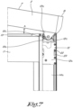
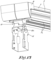
- the basic profile 14 can be provided with a stop 22 for limiting the stroke of the movement of the coupling piece 12 in the height, for example in the form of a peg which is mounted in an aforementioned mounting groove 17 and on the level of a vertical recess 23 in one of the legs 12a or 12b of the coupling piece 12 and which forms a stop 22 for the coupling piece 12 in its highest position as shown in figure 6 , on the one hand, and for the coupling piece 12 at its lowest position as shown in figure 7 , on the other hand.
- a stop 22 for limiting the stroke of the movement of the coupling piece 12 in the height, for example in the form of a peg which is mounted in an aforementioned mounting groove 17 and on the level of a vertical recess 23 in one of the legs 12a or 12b of the coupling piece 12 and which forms a stop 22 for the coupling piece 12 in its highest position as shown in figure 6 , on the one hand, and for the coupling piece 12 at its lowest position as shown in figure 7 , on the other
- the length of the recess determines the stroke over which the coupling piece is movable and is such that the coupling piece 12 does not protrude in its highest position of figure 6 above the support post 9 and in its lowest position of figure 7 still allows a minimum slope of the side guide rail 7 without interference between the side guide rail 7 and the support post 9.
- the stop 22 can be formed by a screw which is used for example to fix the cover profile 16 on the front bar 10 through the recess 23 in the coupling piece 12 and through a bore in the basic profile 14.
- the front bar 10 and the side bars 11 are executed as hollow profiles which serve as roller casing for a roller with a retractable and extendable screen 24 thereon with which the front and the sides can be shielded.
- the invention is also applicable to a terrace canopy 1 without side bars as shown in figure 9 or to a free standing pergola with four support legs.
- side guide rails 7 can also be supported in a location at a distance from their lower end 8, whereby in other words the side guide rails 7 protrude forward beyond the support posts 9 over a certain length.
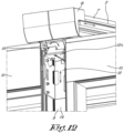
- Figure 10 shows an embodiment whereby two terrace canopies 1 are arranged next to each other as a contiguously continuous double terrace canopy with two roller casings 3 located in each other's extension and two adjacent side guide rails 7.
- adjacent side guide rails 7 are supported at their lower end 8 by one communal support post 9 with one communal coupling piece 12 therein and a communal hinge 13 thereon for both adjacent side guide rails 7.
- the communal support post 9 is in this case composed of a U-shaped base piece 14 with a substantially U-shaped cross-section, the opening of which is oriented to the front and a substantially flat cover profile 16 to cover the opening.
- the communal coupling piece 12 is U-shaped with a U-shaped section which fits in the U-shaped basic profile 14 and is height adjustably mounted therein.
- a seal may be mounted (not shown in the figures).
Landscapes
- Engineering & Computer Science (AREA)
- Architecture (AREA)
- Civil Engineering (AREA)
- Structural Engineering (AREA)
- Building Awnings And Sunshades (AREA)
- Tents Or Canopies (AREA)
Claims (19)
- Terrassenüberdachung, die eine Dachkonstruktion (2) umfasst, die einen ein- und ausfahrbaren Schirm (5) umfasst, der in schrägen für den Schirm (5) bestimmten Seitenführungsschienen (7) geführt ist, wobei die Seitenführungsschienen (7) an oder in einem Abstand von ihrem unteren Ende (8) durch einen hohlen Stützpfosten (9) mittels eines eine horizontalen Welle (13c) umfassenden Scharniers (13) abgestützt sind, wobei die Welle (13c) quer zur Längsrichtung (Q-Q') der Seitenführungsschiene (7) ausgerichtet ist, wobei zur Einstellung der Neigung (A) der seitlichen Führungsschiene (7) das Scharnier (13) an einem Kupplungsstück (12) angebracht ist, das verdeckt in dem hohlen Stützpfosten (9) und höhenverstellbar in dem Stützpfosten (9) montiert ist, dadurch gekennzeichnet, dass das Scharnier (13) auf dem Kupplungsstück (12) in einer Richtung (Y-Y') parallel zu einer Ebene senkrecht zur Achse (13c) des Scharniers (13) verschiebbar angebracht ist.
- Terrassenüberdachung nach Anspruch 1, dadurch gekennzeichnet, dass das Scharnier (13) an der Seitenführungsschiene (7) in Längsrichtung (Q-Q') der Seitenführungsschiene (7) beweglich montiert ist.
- Terrassenüberdachung nach einem der vorhergehenden Ansprüche, dadurch gekennzeichnet, dass der hohle Stützpfosten (9) aus einem offenen Grundprofil (14), das zwei oder drei senkrecht zueinander stehende Schenkel (14a, 14b) umfasst, die einen offenen Raum (15) begrenzen, und aus einem abnehmbaren Abdeckprofil (16) besteht, das den oben genannten Raum (15) in Längsrichtung des Grundprofils (14) abdeckt.
- Terrassenüberdachung nach Anspruch 3, dadurch gekennzeichnet, dass das Kupplungsstück (12) als ein Verstärkungsbügel (20) ausgeführt ist, der mindestens zwei Schenkel (14a, 14b) des Grundprofils (14) miteinander verbindet und der höhenverstellbar an der inneren Seite des Grundprofils (14) angebracht ist.
- Terrassenüberdachung nach Anspruch 3 oder 4, dadurch gekennzeichnet, dass das Kupplungsstück (12) einen im Wesentlichen L- oder U-förmigen Abschnitt enthält, mit dem das Kupplungsstück (12) an der inneren Seite des Grundprofils (14) des Stützpfostens (9) angebracht ist.
- Terrassenüberdachung nach Anspruch 3 oder 4, dadurch gekennzeichnet, dass das Kupplungsstück (12) mit einer Querverstärkung (12c) versehen ist, die mindestens zwei Schenkel des L- oder U-förmigen Profils miteinander verbindet.
- Terrassenüberdachung nach einem der Ansprüche 3 bis 6, dadurch gekennzeichnet, dass das Grundprofil (14) in Längsrichtung mit hinterschnittenen Montagenuten (17) versehen ist, und dass das Kupplungsstück (12) mittels Muttern, die in den Nuten (17) verschiebbar montiert sind und mittels Bolzen in den Nuten durch Bohrungen im Kupplungsstück (12) zum Festklemmen des Kupplungsstücks (12) festgeschraubt werden, auf dem Grundprofil (14) verschiebbar montiert ist
- Terrassenüberdachung nach einem der Ansprüche 3 bis 7, dadurch gekennzeichnet, dass das Grundprofil (14) mit einem Anschlag (22) versehen ist, um die Verschiebung des Kupplungsstück (12) nach oben zu begrenzen, wobei der oben genannte Anschlag (22) so angebracht ist, dass das Kupplungsstück (12) nicht über das obere Ende des Stützpfostens (9) herausragen kann.
- Terrassenüberdachung nach einem der Ansprüche 3 bis 8, dadurch gekennzeichnet, dass das Grundprofil (14) mit einem Anschlag (22) versehen ist, um die Aufwärts- und Abwärtsverschiebung des Kupplungsstücks (12) zu begrenzen, wobei der Anschlag (22) in einer vertikalen Ausnehmung (23) des Kupplungsstücks (12) angebracht ist und wobei die Länge der Ausnehmung den Hub der Bewegung des Kupplungsstücks (12) in der Höhe bestimmt.
- Terrassenüberdachung nach einem der vorhergehenden Ansprüche, dadurch gekennzeichnet, dass das Kupplungsstück (12) einen Träger (12d) zur Abstützung des oben genannten Scharniers (13) enthält.
- Terrassenüberdachung nach Anspruch 10, dadurch gekennzeichnet, dass das Scharnier (13) aus einem Scharnierfuß (13a) und einem Scharnierkopf (13b) besteht, die mittels der oben genannten Welle (13c) gelenkig miteinander verbunden sind, wobei der Scharnierfuß (13a) auf dem Träger (12d) des Kupplungsstücks (12) und der Scharnierkopf (13b) unter der seitlichen Führungsschiene (7) verschiebbar angebracht sind.
- Terrassenüberdachung nach Anspruch 11, dadurch gekennzeichnet, dass der Träger (12d) als Querträgerplatte ausgeführt ist, die mit mindestens einem Langloch (21) versehen ist, das sich parallel zu einer Ebene senkrecht zur Welle (13c) des Scharniers (13) erstreckt und dass der Scharnierfuß (13b) mittels eines oder mehrerer Bolzen (18), die durch das mindestens eine Langloch (21) in dem Scharnierfuß (13a) geschraubt werden, um den Scharnierfuß an dem Träger festzuklemmen, verschiebbar an dem Träger (12d) angebracht ist.
- Terrassenüberdachung nach Anspruch 11 oder 12, dadurch gekennzeichnet, dass der Scharnierfuß (13a) und der Scharnierkopf (13b), im Querschnitt senkrecht zu der Scharnierachse (13c) gesehen, im Wesentlichen dreieckig geformt sind und ihre Spitzen sich über eine bestimmte Höhe überlappen.
- Terrassenüberdachung nach einem der vorhergehenden Ansprüche, dadurch gekennzeichnet, dass der Schirm (5) ein- und ausfahrbar an einer Rolle gelagert ist, die in einem Rollenkasten (3) gelagert ist, der die oberen Enden der Seitenführungsschienen (7) miteinander verbindet, wobei der Rollenkasten (3) mit einer Aufhängung zur Befestigung des Rollenkastens (3) an einer Fassade (4) oder einer anderen Tragkonstruktion versehen ist und wobei der Rollenkasten (3) in der Aufhängung um seine Längsachse schwenkbar vorgesehen ist, um bei der Montage die Neigung (A) der Seitenführungsschienen (7) und damit des Schirms einzustellen.
- Terrassenüberdachung nach einem der vorhergehenden Ansprüche, dadurch gekennzeichnet, dass die seitlichen Führungsschienen (7) mit einem Kanal zur Führung der Seitenkanten des Schirms (5) und/oder einer unteren Leiste (6) an dem unteren Rand des Schirms (5) versehen sind.
- Terrassenüberdachung nach einem der vorhergehenden Ansprüche, dadurch gekennzeichnet, dass die Terrassenüberdachung (1) mit einer vorderen Leiste (10) versehen ist, mit der die Stützpfosten (9) miteinander verbunden sind.
- Terrassenüberdachung nach einem der Ansprüche 14 bis 16, dadurch gekennzeichnet, dass die Terrassenüberdachung (1) mit mindestens einer im Wesentlichen waagerechten seitlichen Leiste (11) für die Verbindung zwischen einem Stützpfosten und der Fassade (4) oder einer anderen Tragkonstruktion, an der der Rollenkasten (3) befestigt ist, versehen ist.
- Terrassenüberdachung nach einem der Ansprüche 16 und/oder 17, dadurch gekennzeichnet, dass die vordere Leiste (10) und/oder eine oder mehrere seitlichen Leisten (11) als Hohlprofile mit einer darin befindlichen Rolle und einem darauf befindlichen ein- und ausfahrbaren Schirm (24) ausgebildet sind.
- Terrassenüberdachung nach einem der vorhergehenden Ansprüche, dadurch gekennzeichnet, dass sie zwei nebeneinander liegende Rollenkästen enthält, die jeweils zwei Seitenführungsschienen umfassen, wobei die nebeneinander liegenden Seitenführungsschienen an oder nahe ihren unteren Enden von einem gemeinsamen Stützpfosten mit einem darin befindlichen gemeinsamen Kupplungsstück und einem daran befindlichen gemeinsamen Scharnier für beide nebeneinander liegenden Seitenführungsschienen getragen werden.
Applications Claiming Priority (1)
| Application Number | Priority Date | Filing Date | Title |
|---|---|---|---|
| BE20215598A BE1029633B1 (nl) | 2021-07-28 | 2021-07-28 | Terrasoverkapping |
Publications (3)
| Publication Number | Publication Date |
|---|---|
| EP4124700A1 EP4124700A1 (de) | 2023-02-01 |
| EP4124700C0 EP4124700C0 (de) | 2024-05-15 |
| EP4124700B1 true EP4124700B1 (de) | 2024-05-15 |
Family
ID=77206908
Family Applications (1)
| Application Number | Title | Priority Date | Filing Date |
|---|---|---|---|
| EP22187627.9A Active EP4124700B1 (de) | 2021-07-28 | 2022-07-28 | Terrassendach |
Country Status (2)
| Country | Link |
|---|---|
| EP (1) | EP4124700B1 (de) |
| BE (1) | BE1029633B1 (de) |
Families Citing this family (2)
| Publication number | Priority date | Publication date | Assignee | Title |
|---|---|---|---|---|
| BE1031330B1 (nl) * | 2023-02-09 | 2024-09-16 | Brustor | Overkapping met zonnescherm |
| BE1031332B1 (nl) * | 2023-02-09 | 2024-09-16 | Brustor | Overkapping met zonnescherm. |
Family Cites Families (6)
| Publication number | Priority date | Publication date | Assignee | Title |
|---|---|---|---|---|
| DE202010011307U1 (de) * | 2009-08-31 | 2010-11-04 | Schmitz-Werke Gmbh + Co Kg | Freisitz-Überdachung nach Art einer Wintergartenmarkise |
| BE1019074A5 (nl) | 2009-12-09 | 2012-02-07 | Kestelyn Nv | Scharnierverbinding voor een schermconstructie. |
| BE1019767A3 (nl) * | 2011-01-14 | 2012-12-04 | Brustor Nv | Zonwering. |
| DE102015001416A1 (de) * | 2015-02-06 | 2016-08-11 | Weinor Gmbh & Co. Kg | Markise mit absenkbaren Führungsschienen |
| KR101609977B1 (ko) * | 2015-02-26 | 2016-04-08 | 박범석 | 루프어닝 장치 |
| EP3354817B1 (de) * | 2017-01-30 | 2019-08-21 | weinor GmbH & Co. KG | Markise mit längeveränderlichen, senkrechten stützen und seitlichem schiebelager |
-
2021
- 2021-07-28 BE BE20215598A patent/BE1029633B1/nl active IP Right Grant
-
2022
- 2022-07-28 EP EP22187627.9A patent/EP4124700B1/de active Active
Also Published As
| Publication number | Publication date |
|---|---|
| EP4124700C0 (de) | 2024-05-15 |
| BE1029633A1 (nl) | 2023-02-21 |
| EP4124700A1 (de) | 2023-02-01 |
| BE1029633B1 (nl) | 2023-02-27 |
Similar Documents
| Publication | Publication Date | Title |
|---|---|---|
| EP4124700B1 (de) | Terrassendach | |
| JP7731032B2 (ja) | テラスキャノピー | |
| US4469159A (en) | Awning | |
| BE1021793B1 (nl) | Scherminrichting | |
| EP4139539B1 (de) | Terrassenüberdachung | |
| US20220205241A1 (en) | Adjustable awning and retractable canopy system | |
| EP4139536A1 (de) | Terrassenüberdachung | |
| EP4392626B1 (de) | Terrassenüberdachung und verfahren zur herstellung davon | |
| EP4139530B1 (de) | Terrassenüberdachung | |
| FI95958B (fi) | Kaltevaan kattoon asennettava ikkuna | |
| EP4396421B1 (de) | Lamellendach, terrassenüberdachung damit und teilesatz und verfahren zur montage davon | |
| EP4352319B1 (de) | Terrassenüberdachung | |
| EP4139537B1 (de) | Terrassenüberdachung | |
| EP2333193A2 (de) | Überdachung | |
| JP2021127561A (ja) | 自立型オーニング | |
| JPH0624120U (ja) | 軒下用日除け |
Legal Events
| Date | Code | Title | Description |
|---|---|---|---|
| STAA | Information on the status of an ep patent application or granted ep patent |
Free format text: STATUS: UNKNOWN |
|
| PUAI | Public reference made under article 153(3) epc to a published international application that has entered the european phase |
Free format text: ORIGINAL CODE: 0009012 |
|
| STAA | Information on the status of an ep patent application or granted ep patent |
Free format text: STATUS: THE APPLICATION HAS BEEN PUBLISHED |
|
| AK | Designated contracting states |
Kind code of ref document: A1 Designated state(s): AL AT BE BG CH CY CZ DE DK EE ES FI FR GB GR HR HU IE IS IT LI LT LU LV MC MK MT NL NO PL PT RO RS SE SI SK SM TR |
|
| STAA | Information on the status of an ep patent application or granted ep patent |
Free format text: STATUS: REQUEST FOR EXAMINATION WAS MADE |
|
| 17P | Request for examination filed |
Effective date: 20230201 |
|
| RBV | Designated contracting states (corrected) |
Designated state(s): AL AT BE BG CH CY CZ DE DK EE ES FI FR GB GR HR HU IE IS IT LI LT LU LV MC MK MT NL NO PL PT RO RS SE SI SK SM TR |
|
| RIC1 | Information provided on ipc code assigned before grant |
Ipc: E04F 10/06 20060101AFI20231201BHEP |
|
| GRAP | Despatch of communication of intention to grant a patent |
Free format text: ORIGINAL CODE: EPIDOSNIGR1 |
|
| STAA | Information on the status of an ep patent application or granted ep patent |
Free format text: STATUS: GRANT OF PATENT IS INTENDED |
|
| INTG | Intention to grant announced |
Effective date: 20240118 |
|
| RAP3 | Party data changed (applicant data changed or rights of an application transferred) |
Owner name: BRUSTOR NV |
|
| GRAS | Grant fee paid |
Free format text: ORIGINAL CODE: EPIDOSNIGR3 |
|
| GRAA | (expected) grant |
Free format text: ORIGINAL CODE: 0009210 |
|
| STAA | Information on the status of an ep patent application or granted ep patent |
Free format text: STATUS: THE PATENT HAS BEEN GRANTED |
|
| AK | Designated contracting states |
Kind code of ref document: B1 Designated state(s): AL AT BE BG CH CY CZ DE DK EE ES FI FR GB GR HR HU IE IS IT LI LT LU LV MC MK MT NL NO PL PT RO RS SE SI SK SM TR |
|
| REG | Reference to a national code |
Ref country code: CH Ref legal event code: EP |
|
| REG | Reference to a national code |
Ref country code: IE Ref legal event code: FG4D |
|
| REG | Reference to a national code |
Ref country code: DE Ref legal event code: R096 Ref document number: 602022003463 Country of ref document: DE |
|
| U01 | Request for unitary effect filed |
Effective date: 20240515 |
|
| U07 | Unitary effect registered |
Designated state(s): AT BE BG DE DK EE FI FR IT LT LU LV MT NL PT SE SI Effective date: 20240617 |
|
| PG25 | Lapsed in a contracting state [announced via postgrant information from national office to epo] |
Ref country code: IS Free format text: LAPSE BECAUSE OF FAILURE TO SUBMIT A TRANSLATION OF THE DESCRIPTION OR TO PAY THE FEE WITHIN THE PRESCRIBED TIME-LIMIT Effective date: 20240915 |
|
| PG25 | Lapsed in a contracting state [announced via postgrant information from national office to epo] |
Ref country code: HR Free format text: LAPSE BECAUSE OF FAILURE TO SUBMIT A TRANSLATION OF THE DESCRIPTION OR TO PAY THE FEE WITHIN THE PRESCRIBED TIME-LIMIT Effective date: 20240515 |
|
| PG25 | Lapsed in a contracting state [announced via postgrant information from national office to epo] |
Ref country code: GR Free format text: LAPSE BECAUSE OF FAILURE TO SUBMIT A TRANSLATION OF THE DESCRIPTION OR TO PAY THE FEE WITHIN THE PRESCRIBED TIME-LIMIT Effective date: 20240816 |
|
| PG25 | Lapsed in a contracting state [announced via postgrant information from national office to epo] |
Ref country code: ES Free format text: LAPSE BECAUSE OF FAILURE TO SUBMIT A TRANSLATION OF THE DESCRIPTION OR TO PAY THE FEE WITHIN THE PRESCRIBED TIME-LIMIT Effective date: 20240515 |
|
| U20 | Renewal fee for the european patent with unitary effect paid |
Year of fee payment: 3 Effective date: 20240917 |
|
| PG25 | Lapsed in a contracting state [announced via postgrant information from national office to epo] |
Ref country code: PL Free format text: LAPSE BECAUSE OF FAILURE TO SUBMIT A TRANSLATION OF THE DESCRIPTION OR TO PAY THE FEE WITHIN THE PRESCRIBED TIME-LIMIT Effective date: 20240515 |
|
| PG25 | Lapsed in a contracting state [announced via postgrant information from national office to epo] |
Ref country code: PL Free format text: LAPSE BECAUSE OF FAILURE TO SUBMIT A TRANSLATION OF THE DESCRIPTION OR TO PAY THE FEE WITHIN THE PRESCRIBED TIME-LIMIT Effective date: 20240515 Ref country code: NO Free format text: LAPSE BECAUSE OF FAILURE TO SUBMIT A TRANSLATION OF THE DESCRIPTION OR TO PAY THE FEE WITHIN THE PRESCRIBED TIME-LIMIT Effective date: 20240815 Ref country code: IS Free format text: LAPSE BECAUSE OF FAILURE TO SUBMIT A TRANSLATION OF THE DESCRIPTION OR TO PAY THE FEE WITHIN THE PRESCRIBED TIME-LIMIT Effective date: 20240915 Ref country code: HR Free format text: LAPSE BECAUSE OF FAILURE TO SUBMIT A TRANSLATION OF THE DESCRIPTION OR TO PAY THE FEE WITHIN THE PRESCRIBED TIME-LIMIT Effective date: 20240515 Ref country code: GR Free format text: LAPSE BECAUSE OF FAILURE TO SUBMIT A TRANSLATION OF THE DESCRIPTION OR TO PAY THE FEE WITHIN THE PRESCRIBED TIME-LIMIT Effective date: 20240816 Ref country code: ES Free format text: LAPSE BECAUSE OF FAILURE TO SUBMIT A TRANSLATION OF THE DESCRIPTION OR TO PAY THE FEE WITHIN THE PRESCRIBED TIME-LIMIT Effective date: 20240515 Ref country code: RS Free format text: LAPSE BECAUSE OF FAILURE TO SUBMIT A TRANSLATION OF THE DESCRIPTION OR TO PAY THE FEE WITHIN THE PRESCRIBED TIME-LIMIT Effective date: 20240815 |
|
| PG25 | Lapsed in a contracting state [announced via postgrant information from national office to epo] |
Ref country code: CZ Free format text: LAPSE BECAUSE OF FAILURE TO SUBMIT A TRANSLATION OF THE DESCRIPTION OR TO PAY THE FEE WITHIN THE PRESCRIBED TIME-LIMIT Effective date: 20240515 |
|
| PG25 | Lapsed in a contracting state [announced via postgrant information from national office to epo] |
Ref country code: RO Free format text: LAPSE BECAUSE OF FAILURE TO SUBMIT A TRANSLATION OF THE DESCRIPTION OR TO PAY THE FEE WITHIN THE PRESCRIBED TIME-LIMIT Effective date: 20240515 Ref country code: SK Free format text: LAPSE BECAUSE OF FAILURE TO SUBMIT A TRANSLATION OF THE DESCRIPTION OR TO PAY THE FEE WITHIN THE PRESCRIBED TIME-LIMIT Effective date: 20240515 |
|
| PG25 | Lapsed in a contracting state [announced via postgrant information from national office to epo] |
Ref country code: SM Free format text: LAPSE BECAUSE OF FAILURE TO SUBMIT A TRANSLATION OF THE DESCRIPTION OR TO PAY THE FEE WITHIN THE PRESCRIBED TIME-LIMIT Effective date: 20240515 |
|
| PG25 | Lapsed in a contracting state [announced via postgrant information from national office to epo] |
Ref country code: SM Free format text: LAPSE BECAUSE OF FAILURE TO SUBMIT A TRANSLATION OF THE DESCRIPTION OR TO PAY THE FEE WITHIN THE PRESCRIBED TIME-LIMIT Effective date: 20240515 Ref country code: SK Free format text: LAPSE BECAUSE OF FAILURE TO SUBMIT A TRANSLATION OF THE DESCRIPTION OR TO PAY THE FEE WITHIN THE PRESCRIBED TIME-LIMIT Effective date: 20240515 Ref country code: RO Free format text: LAPSE BECAUSE OF FAILURE TO SUBMIT A TRANSLATION OF THE DESCRIPTION OR TO PAY THE FEE WITHIN THE PRESCRIBED TIME-LIMIT Effective date: 20240515 Ref country code: CZ Free format text: LAPSE BECAUSE OF FAILURE TO SUBMIT A TRANSLATION OF THE DESCRIPTION OR TO PAY THE FEE WITHIN THE PRESCRIBED TIME-LIMIT Effective date: 20240515 |
|
| PG25 | Lapsed in a contracting state [announced via postgrant information from national office to epo] |
Ref country code: MC Free format text: LAPSE BECAUSE OF FAILURE TO SUBMIT A TRANSLATION OF THE DESCRIPTION OR TO PAY THE FEE WITHIN THE PRESCRIBED TIME-LIMIT Effective date: 20240515 |
|
| REG | Reference to a national code |
Ref country code: DE Ref legal event code: R097 Ref document number: 602022003463 Country of ref document: DE |
|
| PLBE | No opposition filed within time limit |
Free format text: ORIGINAL CODE: 0009261 |
|
| STAA | Information on the status of an ep patent application or granted ep patent |
Free format text: STATUS: NO OPPOSITION FILED WITHIN TIME LIMIT |
|
| 26N | No opposition filed |
Effective date: 20250218 |
|
| PG25 | Lapsed in a contracting state [announced via postgrant information from national office to epo] |
Ref country code: IE Free format text: LAPSE BECAUSE OF NON-PAYMENT OF DUE FEES Effective date: 20240728 |
|
| U20 | Renewal fee for the european patent with unitary effect paid |
Year of fee payment: 4 Effective date: 20250729 |