EP4124593A1 - Fördervorrichtung und verfahren zum fördern von schüttgut - Google Patents
Fördervorrichtung und verfahren zum fördern von schüttgut Download PDFInfo
- Publication number
- EP4124593A1 EP4124593A1 EP21188862.3A EP21188862A EP4124593A1 EP 4124593 A1 EP4124593 A1 EP 4124593A1 EP 21188862 A EP21188862 A EP 21188862A EP 4124593 A1 EP4124593 A1 EP 4124593A1
- Authority
- EP
- European Patent Office
- Prior art keywords
- conveying
- gap
- products
- bulk material
- width
- Prior art date
- Legal status (The legal status is an assumption and is not a legal conclusion. Google has not performed a legal analysis and makes no representation as to the accuracy of the status listed.)
- Granted
Links
Images




Classifications
-
- B—PERFORMING OPERATIONS; TRANSPORTING
- B65—CONVEYING; PACKING; STORING; HANDLING THIN OR FILAMENTARY MATERIAL
- B65G—TRANSPORT OR STORAGE DEVICES, e.g. CONVEYORS FOR LOADING OR TIPPING, SHOP CONVEYOR SYSTEMS OR PNEUMATIC TUBE CONVEYORS
- B65G21/00—Supporting or protective framework or housings for endless load-carriers or traction elements of belt or chain conveyors
- B65G21/20—Means incorporated in, or attached to, framework or housings for guiding load-carriers, traction elements or loads supported on moving surfaces
- B65G21/2045—Mechanical means for guiding or retaining the load on the load-carrying surface
- B65G21/2063—Mechanical means for guiding or retaining the load on the load-carrying surface comprising elements not movable in the direction of load-transport
- B65G21/2072—Laterial guidance means
-
- B—PERFORMING OPERATIONS; TRANSPORTING
- B07—SEPARATING SOLIDS FROM SOLIDS; SORTING
- B07B—SEPARATING SOLIDS FROM SOLIDS BY SIEVING, SCREENING, SIFTING OR BY USING GAS CURRENTS; SEPARATING BY OTHER DRY METHODS APPLICABLE TO BULK MATERIAL, e.g. LOOSE ARTICLES FIT TO BE HANDLED LIKE BULK MATERIAL
- B07B13/00—Grading or sorting solid materials by dry methods, not otherwise provided for; Sorting articles otherwise than by indirectly controlled devices
- B07B13/04—Grading or sorting solid materials by dry methods, not otherwise provided for; Sorting articles otherwise than by indirectly controlled devices according to size
- B07B13/05—Grading or sorting solid materials by dry methods, not otherwise provided for; Sorting articles otherwise than by indirectly controlled devices according to size using material mover cooperating with retainer, deflector or discharger
-
- B—PERFORMING OPERATIONS; TRANSPORTING
- B07—SEPARATING SOLIDS FROM SOLIDS; SORTING
- B07B—SEPARATING SOLIDS FROM SOLIDS BY SIEVING, SCREENING, SIFTING OR BY USING GAS CURRENTS; SEPARATING BY OTHER DRY METHODS APPLICABLE TO BULK MATERIAL, e.g. LOOSE ARTICLES FIT TO BE HANDLED LIKE BULK MATERIAL
- B07B13/00—Grading or sorting solid materials by dry methods, not otherwise provided for; Sorting articles otherwise than by indirectly controlled devices
- B07B13/04—Grading or sorting solid materials by dry methods, not otherwise provided for; Sorting articles otherwise than by indirectly controlled devices according to size
- B07B13/07—Apparatus in which aggregates or articles are moved along or past openings which increase in size in the direction of movement
-
- B—PERFORMING OPERATIONS; TRANSPORTING
- B07—SEPARATING SOLIDS FROM SOLIDS; SORTING
- B07B—SEPARATING SOLIDS FROM SOLIDS BY SIEVING, SCREENING, SIFTING OR BY USING GAS CURRENTS; SEPARATING BY OTHER DRY METHODS APPLICABLE TO BULK MATERIAL, e.g. LOOSE ARTICLES FIT TO BE HANDLED LIKE BULK MATERIAL
- B07B13/00—Grading or sorting solid materials by dry methods, not otherwise provided for; Sorting articles otherwise than by indirectly controlled devices
- B07B13/14—Details or accessories
- B07B13/18—Control
-
- B—PERFORMING OPERATIONS; TRANSPORTING
- B65—CONVEYING; PACKING; STORING; HANDLING THIN OR FILAMENTARY MATERIAL
- B65B—MACHINES, APPARATUS OR DEVICES FOR, OR METHODS OF, PACKAGING ARTICLES OR MATERIALS; UNPACKING
- B65B11/00—Wrapping, e.g. partially or wholly enclosing, articles or quantities of material, in strips, sheets or blanks, of flexible material
- B65B11/50—Enclosing articles, or quantities of material, by disposing contents between two sheets, e.g. pocketed sheets, and securing their opposed free margins
- B65B11/52—Enclosing articles, or quantities of material, by disposing contents between two sheets, e.g. pocketed sheets, and securing their opposed free margins one sheet being rendered plastic, e.g. by heating, and forced by fluid pressure, e.g. vacuum, into engagement with the other sheet and contents, e.g. skin-, blister-, or bubble- packaging
-
- B—PERFORMING OPERATIONS; TRANSPORTING
- B65—CONVEYING; PACKING; STORING; HANDLING THIN OR FILAMENTARY MATERIAL
- B65B—MACHINES, APPARATUS OR DEVICES FOR, OR METHODS OF, PACKAGING ARTICLES OR MATERIALS; UNPACKING
- B65B35/00—Supplying, feeding, arranging or orientating articles to be packaged
- B65B35/30—Arranging and feeding articles in groups
- B65B35/34—Arranging and feeding articles in groups by agitators or vibrators
-
- B—PERFORMING OPERATIONS; TRANSPORTING
- B65—CONVEYING; PACKING; STORING; HANDLING THIN OR FILAMENTARY MATERIAL
- B65G—TRANSPORT OR STORAGE DEVICES, e.g. CONVEYORS FOR LOADING OR TIPPING, SHOP CONVEYOR SYSTEMS OR PNEUMATIC TUBE CONVEYORS
- B65G27/00—Jigging conveyors
- B65G27/04—Load carriers other than helical or spiral channels or conduits
-
- B—PERFORMING OPERATIONS; TRANSPORTING
- B65—CONVEYING; PACKING; STORING; HANDLING THIN OR FILAMENTARY MATERIAL
- B65G—TRANSPORT OR STORAGE DEVICES, e.g. CONVEYORS FOR LOADING OR TIPPING, SHOP CONVEYOR SYSTEMS OR PNEUMATIC TUBE CONVEYORS
- B65G43/00—Control devices, e.g. for safety, warning or fault-correcting
- B65G43/08—Control devices operated by article or material being fed, conveyed or discharged
-
- B—PERFORMING OPERATIONS; TRANSPORTING
- B65—CONVEYING; PACKING; STORING; HANDLING THIN OR FILAMENTARY MATERIAL
- B65G—TRANSPORT OR STORAGE DEVICES, e.g. CONVEYORS FOR LOADING OR TIPPING, SHOP CONVEYOR SYSTEMS OR PNEUMATIC TUBE CONVEYORS
- B65G47/00—Article or material-handling devices associated with conveyors; Methods employing such devices
- B65G47/22—Devices influencing the relative position or the attitude of articles during transit by conveyors
- B65G47/24—Devices influencing the relative position or the attitude of articles during transit by conveyors orientating the articles
-
- B—PERFORMING OPERATIONS; TRANSPORTING
- B65—CONVEYING; PACKING; STORING; HANDLING THIN OR FILAMENTARY MATERIAL
- B65G—TRANSPORT OR STORAGE DEVICES, e.g. CONVEYORS FOR LOADING OR TIPPING, SHOP CONVEYOR SYSTEMS OR PNEUMATIC TUBE CONVEYORS
- B65G47/00—Article or material-handling devices associated with conveyors; Methods employing such devices
- B65G47/52—Devices for transferring articles or materials between conveyors i.e. discharging or feeding devices
- B65G47/68—Devices for transferring articles or materials between conveyors i.e. discharging or feeding devices adapted to receive articles arriving in one layer from one conveyor lane and to transfer them in individual layers to more than one conveyor lane or to one broader conveyor lane, or vice versa, e.g. combining the flows of articles conveyed by more than one conveyor
- B65G47/71—Devices for transferring articles or materials between conveyors i.e. discharging or feeding devices adapted to receive articles arriving in one layer from one conveyor lane and to transfer them in individual layers to more than one conveyor lane or to one broader conveyor lane, or vice versa, e.g. combining the flows of articles conveyed by more than one conveyor the articles being discharged or distributed to several distinct separate conveyors or to a broader conveyor lane
-
- B—PERFORMING OPERATIONS; TRANSPORTING
- B65—CONVEYING; PACKING; STORING; HANDLING THIN OR FILAMENTARY MATERIAL
- B65G—TRANSPORT OR STORAGE DEVICES, e.g. CONVEYORS FOR LOADING OR TIPPING, SHOP CONVEYOR SYSTEMS OR PNEUMATIC TUBE CONVEYORS
- B65G2201/00—Indexing codes relating to handling devices, e.g. conveyors, characterised by the type of product or load being conveyed or handled
- B65G2201/04—Bulk
Definitions
- the present invention relates to a conveying device and a method for conveying bulk material comprising a large number of products, in particular medical or pharmaceutical products, and broken products thereof.
- Products present in the form of bulk goods can be, for example, medical or pharmaceutical products, foodstuffs and food supplements.
- packaging machines for packaging such products the products are fed to a filling device by means of a conveyor device, which fills the products into appropriate packaging. Examples include blister machines for packaging products in blister packs or bottle lines for packaging products in bottle-like containers.
- product breakage in addition to essentially undamaged products. If product breakage gets into the packaging, the corresponding packaging is generally rejected and is rejected and destroyed. This reduces the output of the packaging machine and generates costs through material consumption and disposal. In addition, product breakage can lead to malfunctions in the conveyor device, the filling device and possibly other processing stations.
- control systems which detect and separate product breakage before the packaging is filled.
- Such control systems can include camera systems for detecting product breakage, with mechanical ejection devices or suction devices separating the detected product breakage from the products.
- camera systems for detecting product breakage
- suction devices separating the detected product breakage from the products.
- such systems are expensive and require a relatively large amount of space.
- perforated plates which have a large number of holes through which products in the form of bulk goods are conveyed, represent a more cost-effective possibility. Broken product should fall through the holes and be separated. With perforated plates, however, reliable separation can usually only be achieved for very small fragments and certain product shapes.
- the first and the second conveying element are arranged at a distance from one another in the conveying direction, so that a gap is formed between the first and the second conveying element, the cover element being arranged over the gap and over a section of the first and the second conveying element, bordering the gap.
- the gap has a first width in the conveying direction according to a separation criterion such that broken product can pass through the gap and products are prevented from passing through the gap.
- the gap is consequently designed in such a way that broken product falls through the gap while products are being moved across the gap. In this way, broken product is automatically and reliably separated, while products continue to be conveyed without significantly affecting output. As a result, product breakage does not get into the packaging, so that a related control and ejection of defective packaging can be omitted.
- the formation of the conveying channel between the cover element and the first and the second conveying element and the consequent upward delimitation of the conveying channel by the cover surface can at least partially influence the alignment of the products in the region of the gap and reliably separate the broken product through the gap become.
- the products of the bulk material are preferably medical or pharmaceutical products.
- the medical or pharmaceutical products can be present as solids, for example in the form of tablets, capsules, coated tablets, oblongs, etc.
- the bulk products can also be food or food supplements, such as chewing gum, lozenges, candies or the like, as well as minerals, vitamins, fatty acids or the like in tablet or capsule form.
- Processs herein refers to products that are substantially intact.
- Product breakage in contrast, refers to products that are damaged, i.e. no longer essentially intact.
- the distinction between products and product breakage is based on the predefined separation criterion. The separation criterion depends on the product size. It may differ for different product types. Due to the precisely specified dosage of an active ingredient contained in medical and pharmaceutical products, it may be necessary that exclusively completely undamaged products are packed and already minimally damaged products are separated. On the other hand, with foodstuffs such as chewing gum or sweets, where the focus is primarily on enjoyment, it can be sufficient to separate only badly damaged products and to pack the rest of the products.
- the first width of the gap is now selected according to this predefined separation criterion in such a way that broken product is reliably separated through the gap and products are moved across the gap as unhindered as possible.
- the gap consequently has the first width in such a way that the passage of broken product through the gap is ensured.
- the gap with the first width is designed in such a way that broken product is reliably separated through the gap, ie moving broken product across the gap is prevented. This ensures that no product breakage reaches the second conveyor element and is thus fed to further processing.
- the broken product passes through the gap by free fall of the broken product through the gap and thus without additional deflection means, such as flaps, slides, air nozzles or the like, which specifically capture and remove the broken product.
- additional deflection means such as flaps, slides, air nozzles or the like, which specifically capture and remove the broken product.
- the products move across the free gap and thus without the support of additional support or deflection means that could temporarily close or block the gap.
- a collecting container for catching the broken product can be provided under the gap.
- the gap preferably extends over the entire width of the first and the second conveying surface.
- the width of the first and second conveying surfaces is defined perpendicular to the conveying direction and, for substantially planar conveying surfaces, in a plane with the first and second conveying surfaces.
- first and the second conveying surface are arranged essentially in one plane. This can reduce the risk of products tipping over during the transition from the first to the second conveying surface and becoming jammed between the first and the second conveying element and the covering element.
- a distance between the cover surface and the first or second conveying surface in a direction perpendicular to the cover surface defines a height of the at least one conveying channel.
- the height of the at least one conveying channel is preferably defined as a function of the product size and possibly the product geometry.
- the at least one conveying channel can have a height that is smaller than two products arranged one above the other on the first or second conveying surface, so that the bulk material can only enter the at least one conveying channel in a single layer. If the products have different dimensions in different directions, the height of the at least one conveying channel can also be selected such that the products can only enter the conveying channel in a specific orientation or products cannot enter the conveying channel in a specific orientation.
- the at least one conveyor channel preferably has a height that prevents the products from tipping over an edge of the first conveyor element that delimits the gap.
- the height of the at least one conveying channel is therefore preferably between 1.0 and 1.5 times, more preferably between 1.05 and 1.4 times, even more preferably between 1.1 and 1.5 times 1.2 times the height of the products perpendicular to the first or second conveyor surface.
- the at least one conveying channel has a height that is less than a length of the products in the conveying direction. In this way, by suitably designing the gap and the at least one conveying channel, the products can be moved across the gap as reliably as possible, which increases the output of the conveying device.
- the cover element is preferably fixed on the first and/or on the second conveying element. This means that the cover element is always arranged at a fixed distance from the first or second conveying surface, as a result of which it can be ensured that the predefined height of the at least one conveying channel is maintained at all times. In particular, the cover element cannot be moved relative to that of the first and second conveying element to which it is fixed. In order to allow access to the gap, however, the cover element can be detachably connected to the respective one of the first and the second conveying element.
- the first and the second conveying element are preferably designed in the form of plates. Each conveying element can then be a substantially rectangular plate, for example made of metal or plastic. A top surface of the first and second conveying elements comprises the first and second conveying surfaces, respectively.
- the bulk material is moved on the first and the second conveying surface relative to the first or conveying element, for example by vibrations of the conveying elements.
- the first and the second conveying element do not comprise any conveyor belts or other movable conveying means for transporting products, in which case the products generally do not move in the conveying direction relative to the conveying surfaces.
- the first and the second conveying element can be designed as simply as possible.
- the conveying device is preferably a vibrating conveyor, for example in the form of a vibrating chute, as is known for conveying bulk material, in particular medical and pharmaceutical products.
- the first and the second conveying element then form part of the vibrating chute.
- the conveying device can comprise a drive device which is coupled to the first or the second conveying element in order to set them in vibration.
- the drive device is preferably coupled to the first conveying element and the first and the second conveying element are connected to one another in order to transmit the vibrations.
- first and second conveying elements are formed as separate components. They can be connected to each other.
- first and the second conveying element can be movably connected to one another, for example in such a way that the first and the second conveying element can be moved relative to one another parallel to the conveying direction.
- the first and/or the second conveying element can be moved relative to one another in the conveying direction and the width of the gap can be adjusted.
- the first and/or the second conveying element can be moved relative to one another exclusively in the conveying direction.
- the first and second conveying surfaces then remain arranged essentially in one plane, while the width of the gap is adjustable. Due to the adjustability of the gap, the conveying device can be easily adapted to the predefined separation criterion as well as to different product sizes and geometries.
- first and/or the second conveyor element can be moved relative to one another can be achieved in that only one of the two conveyor elements can be moved relative to the other conveyor element.
- the second conveying element is movable to and fro relative to the first conveying element, while the first conveying element is immovable with respect to the second conveying element.
- both conveying elements can also be movable.
- the conveying device can comprise at least one actuator which moves the first and the second conveying element relative to one another.
- the actuating drive can be, for example, a hydraulic, pneumatic, electrical or mechanical linear drive.
- a stationary component of the at least one actuator is preferably connected to the first conveyor element and a movable component of the at least one actuator is connected to the second conveyor element.
- the first and the second conveyor element can be moved relative to one another in the conveying direction between the first position and a second position, the gap having a second width in the second position, which is greater than the first width. If the gap has the second width, the passage is of products through the gap. Products jammed in the area of the gap consequently fall through the gap, as a result of which the jamming is released.
- the most reliable possible solution to jamming can be achieved if the second width is greater than a maximum dimension of the products in the conveying direction.
- the conveying device can be configured to move the first and the second conveying element from the first position to the second position at predefined time intervals, to leave them in the second position for a predefined period of time, and then to move them back to the first position. Any deadlocks that may be present are then automatically resolved without the need for a complex detection of products and deadlocks and a corresponding control system.
- the first and the second conveying element can also be moved from the first to the second position in a sensor-controlled manner, as is described in more detail here with reference to suitable sensors.
- the at least one conveying channel is divided into a plurality of conveying channels, so that the conveying device has a plurality of conveying channels which extend in the conveying direction and are arranged next to one another in a direction transverse to the conveying direction.
- the conveying device preferably has the plurality of conveying channels at least in that section of the first conveying element which is covered by the covering element. However, the plurality of conveying channels can also extend beyond the covering element on the first conveying element and optionally on the second conveying element.
- the conveying channels of the plurality of conveying channels can have, for example, a rectangular, a V-shaped or a U-shaped cross section.
- the conveying channels of the plurality of conveying channels are particularly preferably designed in such a way that exactly one row of products arranged one behind the other can move through a conveying channel. However, two or more products do not fit next to each other in a conveyor channel. Consequently, a width of each conveying channel of the plurality of conveying channels is preferably smaller than the width of two products, the width being defined in a direction perpendicular to the conveying direction and perpendicular to the height of the conveying channels, respectively.
- the gap preferably extends over the width of a plurality of conveying channels, particularly preferably over the width of all conveying channels and thus over the entire width of the first conveying surface. If the gap does not extend over the entire width of all conveying channels, at least one second gap is provided, which extends over the remaining width. All conveying channels of the plurality of conveying channels lead to the gap or to a gap, so that a separation of broken product in the conveying device is ensured.
- the conveying device can also comprise a plurality of guide elements which extend in the conveying direction, are arranged next to one another in a direction transverse to the conveying direction and the plurality of conveying channels for the bulk material transverse to the conveying direction, i.e. in a first transverse direction perpendicular to the Limit the conveying direction and perpendicular to the height of the conveying channels at the side.
- the plurality of guide elements preferably extends at least in the section of the first conveying element that is covered by the cover element up to the gap.
- a second transverse direction is defined perpendicular to the conveying direction and parallel to the height of the conveying channels or perpendicular to the cover surface.
- the cover element can delimit the plurality of conveying channels at the top, ie parallel to the second transverse direction.
- the first conveying surface and optionally also the second conveying surface can delimit the plurality of conveying channels in a section of the first or the second conveying element which adjoins the gap at the bottom.
- the plurality of guide elements In order to move the products as reliably as possible across the gap and to further reduce the risk of jamming, it is preferred that the plurality of guide elements continue to extend across the gap. It can thereby be achieved that the alignment of the products in the conveying direction is not influenced in the first transverse direction when the products are moved across the gap.
- the plurality of guide members are arranged only in a downstream portion of the first impeller with respect to the conveying direction, and no guide members are provided in an upstream portion of the first impeller.
- the bulk material can thus be guided onto the first conveying element in the upstream section and the products of the bulk material and the broken product contained therein can be introduced into the conveying channels in the conveying direction in the course of conveying the bulk material.
- the plurality of guide elements can be formed, for example, by a plurality of strips, which are preferably attached to an upper side of the first conveying element.
- a plurality of grooves can be formed in the upper side of the first conveying element in order to form the plurality of conveying channels. Side walls of the grooves remaining between the grooves then form the plurality of guide elements.
- the plurality of guide elements can also be formed on the second conveying element.
- the plurality of guide elements is preferably fixed or attached to the first conveying element and protrudes beyond the first conveying element in the conveying direction, so that the plurality of guide elements extends across the gap.
- the plurality of guide elements particularly preferably extends beyond the gap and at least partially over the second conveying element. In this way, the products are reliably guided across the gap.
- the plurality of Guide elements are then not connected to the second conveying element, so that this can still be moved relative to the first conveying element.
- a distance between two adjacent guide elements of the plurality of guide elements defines a width of a conveying channel of the plurality of conveying channels, which is delimited by the two adjacent guide elements.
- the conveying channels of the plurality of conveying channels each have a width and a height such that the products have a predefined alignment with respect to the conveying direction and maintain it at least in the area of the plurality of guide elements. Consequently, the products only fit into a conveyor channel if they are oriented in the predefined orientation. As long as the products are oriented in an orientation deviating from the predefined orientation, they do not get into the plurality of conveyor channels and are retained in front of them.
- a first dimension of the products is defined in the predefined orientation parallel to the conveying direction, with the separation criterion being defined as a function of the first dimension.
- the first dimension of the products can correspond to a length of the products and the separation criterion can be defined as described above.
- the length is the largest dimension of the products.
- the conveying channels can have a width and a height that are smaller than the length of the products. In this way, products can only enter the conveying channels if their longitudinal direction is oriented parallel to the conveying direction.
- each conveying channel of the plurality of conveying channels is between 1.0 and 1.5 times, more preferably between 1.05 and 1.4 times, even more preferably between 1.1 and 1.2 times the height of the products in the predefined orientation.
- the width of each conveying channel of the plurality of conveying channels is between 1.0 and 1.5 times, more preferably between 1.05 and 1.4 times, even more preferably between 1.1 and 1.2 times the width of the products in the predefined orientation.
- the conveyor device preferably has an alignment device which is set up to align the products of the bulk material, in particular in the first predefined alignment.
- the aligning device is preferably arranged upstream with respect to the conveying direction directly in front of the plurality of guide elements or at a beginning of the plurality of guide elements, eg above a starting section of the plurality of guide elements. Products that are not aligned as desired are retained by the aligner, remain in front of the aligner, and are realigned.
- the alignment device can, for example, be a roller, in particular one Rag roller or a brush roller, or comprise a brush, and having a longitudinal axis extending parallel to the first transverse direction.
- the alignment device is arranged relative to the first conveying surface in such a way that it engages with the bulk material conveyed in the conveying direction.
- the aligning device By engaging with the alignment device, the products of the bulk material and the broken product contained therein are reoriented and products pass between the plurality of guide elements as soon as they have assumed the desired alignment. Depending on the size of the broken product, it can enter the plurality of conveying channels in any orientation or independently of a desired orientation.
- the aligning device also causes the bulk material to be arranged in only one layer downstream of the aligning device.
- the conveying device comprises at least one sensor for detecting jamming of bulk material, in particular of products but possibly also product breakage, in the gap.
- the gap can be opened specifically to the second width when a deadlock to be released is detected. Opening the gap at regular time intervals, which entails the separation of intact products and thus a reduction in output, can then be dispensed with.
- the actuator which moves the first and the second conveying element relative to one another, can be set up to move the first and the second conveying element relative to one another from the first to the second position in response to a signal from the at least one sensor.
- the conveyor device includes a control device and the at least one sensor is set up to transmit a signal to the control device that is indicative of a jammed product, and the control device is set up to actuate the actuator in response to the signal received, to open the gap.
- the at least one sensor can be designed and arranged in different ways, as described below.
- the at least one sensor is preferably designed in such a way that it detects jamming in all of the conveying channels of the plurality of conveying channels. Exactly one sensor or a plurality of sensors can be provided for this purpose. If there is a plurality of sensors, each sensor is preferably assigned to a part of the plurality of conveying channels.
- the sensors of the plurality of sensors can all be designed and arranged according to one of the embodiments described below or can be combined from these embodiments as desired.
- the at least one sensor can be arranged above the gap and set up to detect bulk material or product breakage remaining in the gap.
- the at least one sensor can be arranged above the cover element, which is then preferably at least partially or completely transparent.
- the at least one sensor can be set up to detect bulk material or broken product in the area of the gap and to record a period of time for which the bulk material or broken product is in the area of the gap. If the recorded period exceeds a predefined limit value, a deadlock can be assumed and such a deadlock is detected.
- the at least one sensor could also register a movement of the detected products in the conveying direction and detect a jam when no more movement of a detected product is detected.
- the at least one sensor can be arranged in the gap or below the gap, preferably below the first and/or the second conveyor element, and set up to detect bulk material remaining in the gap or the passage of bulk material through the gap.
- the at least one sensor in this embodiment is designed as a light barrier, with the light beam preferably being arranged in the gap. If broken product falls through the gap, the passage of bulk material is detected by briefly interrupting the light beam. If a product or large broken product tips into the gap and jams, the product or broken product remaining in the area of the gap is detected, for example, by the fact that the light beam is interrupted for a long time or permanently.
- the at least one sensor is arranged upstream of the gap with respect to the conveying direction, preferably upstream of the cover element, and is set up to detect bulk material that is accumulating. For example, if a product gets stuck in the gap or in one of the plurality of conveying channels, it blocks subsequent products and product breakage. As a result, the bulk material accumulates.
- the at least one sensor can be set up to detect the bulk material in front of the cover element and to recognize that the bulk material is accumulating or is not moving any further in the conveying direction. A deadlock can then be assumed and such a deadlock is recognized.
- the at least one sensor can be embodied as an optoelectronic sensor, for example.
- the at least one sensor can be arranged downstream of the gap with respect to the conveying direction, preferably assigned to a processing station downstream of the conveying device, and set up to detect a falling output of the conveying device.
- the at least one sensor in this embodiment is designed as a fill level sensor in a subsequent processing station, which is set up to detect that too few products are being supplied by the conveyor device, which means that products are jammed in the conveyor device.
- the present invention also relates to a blister machine with a conveying device according to the invention Variety of products, in particular medical or pharmaceutical products, and broken products thereof, a conveyor device according to the invention for separating broken products and conveying the products in a conveying direction, and a filling station for filling the products into bowls.
- the product store is set up to deliver the bulk material to the conveying device, in particular to the first conveying element, and the conveying device is set up to convey the products of the bulk material to the filling station. All the features and advantages described herein with regard to the conveyor device according to the invention therefore also apply to the blister machine and vice versa.
- the blister machine may further comprise a forming station for forming the cups into a forming sheet, located before the filling station, and a sealing station for sealing a cover sheet to the forming sheet, located after the filling station.
- the blister machine can include a punching station for punching out blister packs from the film composite of formed film and cover film.
- the gap is consequently designed in such a way that broken product falls through the gap while products are being moved across the gap. In this way, broken product is automatically and reliably sorted out, while products continue to be conveyed without significantly affecting output.
- the method according to the invention is particularly preferably carried out by means of the conveyor device according to the invention or a blister machine comprising a conveyor device according to the invention. All the features and advantages described in connection with the conveyor device and the blister machine can therefore be transferred analogously to the method according to the invention and vice versa.
- the separation of broken product preferably includes the free fall of the broken product through the gap, in particular without the broken product being caught and removed by additional deflection means such as flaps, slides, air nozzles or the like.
- additional deflection means such as flaps, slides, air nozzles or the like.
- the products are moved across the free gap and thus without additional support from other support or deflection means that would temporarily close or block the gap. This results in a very reliable, but nevertheless simple and cost-effective way of separating the broken product, which does not require any additional components to be driven and controlled.
- Moving the products across the gap may include guiding the products laterally in the area of the gap, for example by means of the plurality of guide elements, in order to ensure a specific orientation of the products and to reduce the risk of jamming of the products in the area of the gap.
- Moving the products across the gap may also include preventing the products from tipping into the gap, in particular by holding down the products in the area of the gap, for example by means of the cover element. This can also reduce the risk of jamming in the area of the gap.
- the products By laterally guiding the products and preventing the products from tipping, it is achieved that the products essentially retain an orientation that has been imposed on them (e.g. the predefined orientation) when moving across the gap and are thus moved across the gap reliably and without jamming.
- an orientation that has been imposed on them e.g. the predefined orientation
- the products always reach the gap in the predefined alignment, so that the first width of the gap and the separation criterion can be selected depending on the first dimension, and reliable separation is ensured.
- Moving the products across the gap may then include guiding the products across the gap such that the products substantially maintain the predefined orientation, for example by lateral guiding and preventing tipping as previously described.
- That the products essentially maintain the predefined orientation means that the products have the predefined orientation both immediately before and immediately after the gap.
- the products can also have the predefined alignment in the area of the gap.
- the products due to small distances between the products and the guide elements and to the cover element and due to tolerances in the dimensions of the products, it is possible for the products to tilt minimally when crossing the edges of the first and second conveyor elements that delimit the gap. However, further tilting is immediately prevented, as previously described.
- the method can also include the definition of the separation criterion or the selection of a suitable separation criterion, in particular as initially described by way of example.
- the method particularly preferably includes setting the first width of the gap according to the predefined separation criterion before the bulk material is conveyed to the gap. Adjusting the first width may include moving the first and second conveying elements relative to one another, for example by moving the second conveying element relative to the first conveying element.
- the first width can be set manually or automatically by means of the control device based on a width entered by a user, a width selected by the user or a separation criterion specified by the user.
- the method preferably includes opening the gap from the first width to a second width, which is larger than the first width, preferably by means of the actuator.
- the gap can be opened at predetermined time intervals or, as described above, under sensor control.
- the at least one sensor preferably provides the signal to the control device, which, in response to the signal, controls the actuator to open the gap.
- the gap is then opened by means of the actuator.
- a deadlock can also be detected jointly by the at least one sensor and the control device.
- the control device can compare actual values, which are determined by the sensor, with target values.
- the at least one sensor can be selected from the sensor embodiments already described.
- a plurality of sensors according to one of these embodiments or from a combination of these embodiments can also be provided.
- detecting a deadlock includes detecting a period of time for which the products or the broken product are in the area of the gap, comparing the detected period of time with a predefined limit value, and determining a deadlock if the detected period of time is greater than is the predefined limit.
- the products or the rough product breakage can first be identified.
- the at least one sensor is preferably designed according to the first embodiment described above.
- the detection of a jam includes the detection of a broken product passing through the gap and the determination of a jam when no passage is detected or passage can no longer be detected, for example because a product is blocking the at least one sensor.
- the at least one sensor is preferably designed according to the second embodiment described above.
- the detection of a jam includes the detection of the bulk material upstream of the gap, the detection of accumulating bulk material upstream of the gap, and the determination of a jam when accumulating bulk material is identified.
- the at least one sensor is preferably designed according to the third embodiment described above.
- detecting a jam includes detecting the plurality of products of the bulk material downstream of the gap, detecting a decreasing output of the products downstream of the gap, and determining a jam when a decreasing output is detected.
- the at least one sensor is preferably designed according to the fourth embodiment described above.
- the conveyor device 2 is set up to feed products present in the form of bulk goods to a processing station 4 .
- the bulk material also includes broken products, which must be separated out during transport to the processing station 4 in order to only process products of a predetermined quality.
- the processing station 4 can be, for example, a filling station of a blister machine, as with reference to FIG 9 explained.
- the bulk material comprising a large number of products, in particular medical or pharmaceutical products, and broken products thereof is made available in a product store 6, for example.
- the product store 6 is set up to receive the bulk material and deliver it to the conveyor device 2 .
- the conveying device 2 comprises a first conveying element 8 which has a first conveying surface 10 and a second conveying element 12 which has a second conveying surface 14 .
- the first and the second conveying surface 10, 14 are arranged on the upper side of the respective conveying element 8, 12.
- the bulk material is conveyed in a conveying direction F on the first conveying surface 10 and the second conveying surface 14 .
- the second conveying element 12 is arranged downstream of the first conveying element 8 .
- the first and the second conveyor element 8, 12 can be plate-shaped, as is known, for example, from vibratory conveyors.
- the bulk material is moved relative to the conveying surfaces 10 , 14 by vibrations of the first and second conveying elements 8 , 12 .
- the conveyor device 2 can have a drive device 16, which is coupled to one of the first and the second conveyor element 8, 12, here to the first conveyor element 8.
- the vibrations from the first to the second conveyor element 8, 12 these can be connected to each other, such as from figure 5 and 6 emerges.
- the first and the second conveying element 8, 12 are arranged at a distance from one another in the conveying direction F, so that a gap 18 with a width B is formed between the first and the second conveying element 8, 12.
- the gap 18 has a first width B1.
- the first width B1 is selected according to a predefined separating criterion in such a way that broken product falls through the gap 18 and products move across the gap 18 in order in this way to separate the broken product and only process products of sufficient quality further.
- a collecting container 20 for receiving the broken product falling through the gap 18 can be arranged under the gap 18 .
- the width B of the gap 18 is particularly preferably adjustable in order to be able to adjust it according to the predefined separation criterion and in order to be able to loosen any products that are jammed in the area of the gap 18 .
- the first and the second conveying element 8, 12 can be moved relative to one another in the conveying direction F, as with reference to FIG Figures 6a and 6b described in more detail.
- an actuator 21 is provided, which is coupled at least to the second conveying element 12 in order to move it with respect to the first conveying element 8 .
- the conveyor device 2 further comprises a cover element 22 with a cover surface 24 which is arranged essentially parallel to the first conveying surface 10 and the second conveying surface 12 and faces them.
- the cover element 22 is arranged over the gap 18 and over a respective section 8a, 12a of the first and the second conveying element 8, 12 which adjoins the gap 18.
- the covering surface 24, the first conveying surface 10 and the second conveying surface 14 form at least one conveying channel 26, in which the bulk material on the first conveying surface 10 is conveyed to the gap 18 and products on the second conveying surface 14 are conveyed further in the conveying direction F.
- the at least one conveyor channel 26 has a height H, which is defined by the distance between the cover surface 24 and the conveyor surfaces 10, 14 and perpendicular to the cover surface 24.
- the products in the area of the gap 18 preferably have a predefined alignment.
- the at least one conveying channel 26 can have a height H such that products only fit into the at least one conveying channel 26 in a certain orientation or products of certain orientation(s) do not fit into the at least one conveying channel 26.
- the conveyor device 2 can have a plurality of guide elements 28 and/or an alignment device arranged upstream of the cover element 22 with respect to the conveying direction F 30 as described below with reference to FIG 2 and 3 described in detail.
- the 3 is a sectional view of the conveyor device 2 in the area of the first conveyor element 8 and the cover element 22 along the line III-III in 2 .
- the alignment device 30 can include a roller 34, for example, which can be designed as a rag roller or brush roller.
- the roller 34 is arranged in such a way that its longitudinal axis 34a extends perpendicularly to the conveying direction F and parallel to the first conveying surface 10 . Upstream of the aligning device 30 the bulk material can be arranged in a random manner and in multiple layers on the first conveying element 8 .
- the roller 34 is arranged in such a way that it engages with the bulk material conveyed in the conveying direction F, as a result of which the bulk material is partially retained and reoriented.
- the roller 34 advantageously rotates for this purpose.
- a direction of rotation of the roller 34 is preferably opposite to the conveying direction F in the region of engagement with the bulk material.
- the roller 34 can limit the passage between the roller 34 and the first conveying surface 10 in such a way that the bulk material or the products 32 are only conveyed further in a single layer.
- the passage is preferably already limited to the height H of the at least one conveying channel 26 .
- the alignment device 30 can be arranged above the plurality of guide elements 28 and reorient the bulk material until the products 32 and the broken product enter the conveying channels 26 between the guide elements 28 .
- the plurality of guide elements 28, of which three guide elements 28a, 28b, 28c are shown here, divide the conveying channel 26 into a plurality of conveying channels, of which three conveying channels 26a, 26b, 26c can be seen.
- Both the plurality of conveying channels 26 and the plurality of guide elements 28 run in the conveying direction F and are arranged next to one another in a first transverse direction Q1 perpendicular to the conveying direction F and parallel to the first conveying surface 10 or to the covering surface 24 .
- the plurality of guide elements 28 delimits the plurality of conveying channels 26 in the first transverse direction Q1.
- each conveying channel 26a, 26b, 26c is delimited laterally by two guide elements 28a, 28b, 28c and upwards and downwards by the covering surface 24 and the first conveying surface 10.
- a distance between two adjacent guide elements 28a, 28b defines a width BF of the plurality of conveying channels 26.
- the plurality of conveying channels 26 can have a width BF and a height H such that the products 32 have a predefined orientation with respect to the conveying direction F and are maintained at least in the region of the plurality of guide elements 28 .
- BF and the height H of the plurality of conveying channels 26 are not significantly greater than a width of the products 32 and a height of the products 32, so that the products are prevented from tipping about an axis parallel to the conveying direction F.
- the width BF of the plurality of conveying channels 26 is smaller than a height of the products 32 and both the width BF and the height H of the plurality of conveying channels 26 are smaller than the length L of the products 32. The products 32 can therefore only be be received in the conveying channels 26 in the illustrated, predefined orientation.
- a first dimension of the products 32 here a length L1 of the products 32, is defined parallel to the conveying direction F in the predefined alignment.
- the separation criterion is preferably defined as a function of this first dimension.
- the bulk material comprising a large number of products 32 and broken product 36 of the same is conveyed on the first conveying surface 10 in the conveying direction F to the gap 18 .
- the bulk material can be pre-sorted or aligned by means of the alignment device 30 . Arriving at gap 18, products 32 are moved across gap 18, as shown in FIG Figure 4a shown while broken product 36 falls through gap 18 and is separated thereby, as in FIG Figure 4b shown.
- the first width B1 of the gap 18 is set according to the predefined separation criterion in such a way that the products 32 move across the gap 18 .
- the width B1 is smaller than the length L1 of the products 32 in the predefined orientation and the products 32 are guided in the area of the gap 18 in such a way that they essentially retain the predefined orientation.
- the cover element 22 prevents the products 32 from tipping over an edge 8b of the first conveying element 8 that delimits the gap 18 and into the gap 18 .
- the products 32 Due to the slight play between the products 32 and the first conveying surface 10 as well as the covering surface 24 and a tolerance in the size of the products 32, the products 32 can at most tilt slightly, but are then blocked by the covering element 22 and continue reliably in the conveying direction F via the gap 18 emotional.
- the separation criterion is defined in such a way that only products with a length L greater than 90% of the length L1 of intact products 32 are to be processed further, all parts of products with a length L2 of less than 90% of the length L1 form product breakage 36, such as that in Figure 4b shown section 36.
- the first width B1 of the gap 18 is now set in such a way that broken product 36 falls through the gap 18 and is thereby separated from the products 32. Consequently, the width B1 of the gap should not be significantly less than 90% of the length L1.
- the first width B1 should be approximately 90% of the length L1 in this exemplary embodiment.
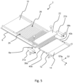
- FIG 5 the essential components of the conveyor device 2 are shown in more detail in a perspective view.
- the first conveying element 8, the second conveying element 12 and the cover element 22 can be seen.
- the features described for the individual components are largely independent of the design of the other components in each case.
- the first conveying element 8 is essentially plate-shaped.
- the plurality of guide elements 28 is arranged on the first conveying element 8 or on the first conveying surface 10 in order to form the plurality of conveying channels 26 .
- the plurality of guide elements 28 extends only in a downstream section of the first conveying element 8, while no guide elements 28 are provided in an upstream section of the first conveying element 8 and the first conveying surface 10 is essentially flat.
- the product store 6 delivers the bulk material onto the first conveying element 8 in this upstream section.
- the plurality of guide channels 26 can be in the form of grooves that are introduced into the upper side of the first conveying element 8 . At least part of the bulk material already falls into the guide channels 26 in a specific orientation during conveyance in the conveying direction F.
- the cover element 22 is fixed here on the first conveying element 8 .
- the cover element 22 is preferably detachably connected to the first conveying element 8, in particular screwed to the first conveying element 8.
- the covering element 22 covers the plurality of conveying channels 26 in the section 8a of the first conveying element 8 adjoining the gap 18 .
- the second conveying element 12 is also plate-shaped and the second conveying surface 14 is essentially flat.
- the plurality of guide elements 28 can extend beyond the first conveying element 8 and at least partially over the second conveying element 12 in order to close the plurality of conveying channels 26 at least in the upstream section 12a of the second conveying element 12, which adjoins the gap 18 form.
- the cover element 22 also extends into the section 12a of the second conveyor element 12.
- the second conveying element 12 can be movably connected to the first conveying element 8 .
- the second conveying element 12 can be slidably mounted on two guide pins 38a, b, which in turn are fixed to the first conveying element 8.
- stop elements can be provided which limit the movement of the second conveying element 12 towards the first conveying element 8 and thereby precisely define the width of the gap 18 .
- the stop elements can be formed, for example, as spacer sleeves 40a, b, which are arranged on the guide pins 38a, b.
- the width B of the gap 18 to be precisely adjustable without stop elements, so that such elements can be dispensed with.
- two actuators 21a, b are provided here, which are coupled to the second conveyor element 12.
- the actuators 21a, b are designed as pneumatic or hydraulic cylinders whose piston rods are connected to the second conveying element 12.
- the actuators 21a, b can consequently move the second conveying element 12 parallel to the conveying direction F. It goes without saying that only one guide pin 38, more than two guide pins 38a, b or similar guide means, and also only one actuator 21 or more than two actuators 21a, b can be provided.
- Figure 6a are the first and the second conveyor element 8, 12 in a first position in which the width of the gap 18 corresponds to the first width B1, which is set according to the predefined separation criterion.
- the first width B1 can be defined as the minimum width of the gap 18 by the spacer sleeves 40a, b.
- the spacer sleeves 40a, b can be exchanged.
- Figure 6b are the first and the second conveyor element 8, 12 in a second position in which the gap 18 has a second width B2, which is greater than the first width B1.
- the gap 18 is opened by moving the second conveying element 12 relative to the first conveying element 8 from the first to the second position.
- any products 32 that are jammed in the area of the gap 18 can be released and separated through the gap 18 .
- the plurality of guide elements 28 preferably extend across the gap 18 to the second conveying element 12 both in the first position and in the second position.
- the actuators 21a, b can move the second conveying element 12 at regular time intervals from the first to the second position and back again in order to automatically release any jams that may occur. Although this represents a very simple and cost-effective way of releasing jamming, it causes the loss of products 32 through the gap 18 with each opening and thus a reduction in output.
- the conveyor device 2 can include at least one sensor for detecting jamming of bulk material in the gap 18 .
- the at least one sensor 42, 44, 46, 48 are described below with reference to FIG 7 and 8 described.
- the sensors 42, 46, 48 are only shown together in 7 shown. It goes without saying that at least one sensor can also be provided according to one of these embodiments. However, a combination of sensors from the various embodiments is also conceivable.
- FIG 7 shows a plan view of the conveyor device 2 in the region of the gap 18 and 8 shows a sectional view of the conveyor device 2 in the area of the gap 18 along the line VIII-VIII in FIG 7 .
- a first sensor 42 according to a first embodiment is shown.
- the first sensor 42 is arranged above the gap 18 and detects bulk material that remains in the gap 18 .
- the cover element 22 can be made transparent in order to enable the detection of bulk material in the area of the gap 18 by means of the first sensor 42 through the cover element 22 . If the first sensor 42 detects only part of the plurality of conveyor channels 26 in the area of the gap 18, as shown, a plurality of first sensors 42 are preferably arranged next to one another in the first transverse direction Q1, so that all conveyor channels 26 in the area of the gap 18 can be monitored .
- the first sensor 42 now detects a bulk material, in particular one of the products 32, in the area of the gap 18 and records a period of time for which the identified bulk material is in the area of the gap 18. If the recorded period is longer than a predefined limit value, a deadlock can be assumed. This is also the case when the first sensor 42 detects that a product 32 is no longer moving in the conveying direction F.
- a second sensor 44 is shown according to a second embodiment.
- the second sensor is arranged in the gap 18 or just below the gap 18 .
- the second sensor 44 can detect bulk material remaining in the gap 18 or the passage of bulk material through the gap 18 .
- the second sensor 44 is designed as a light barrier, which comprises a transmitter 45a and a receiver 45b, between which a light beam 45c, indicated by dashed lines, runs.
- a light barrier which comprises a transmitter 45a and a receiver 45b, between which a light beam 45c, indicated by dashed lines, runs.
- a third sensor 46 according to a third embodiment is in turn 7 to see.
- the third sensor 46 is arranged upstream of the gap 18 and ideally upstream of the cover element 22 and detects bulk material accumulating. If a product 32 gets stuck in the area of the gap 18 in one of the conveying channels 26, it blocks the following bulk material, so that this backs up.
- the third sensor 46 detects such a jam, as a result of which a deadlock is detected.
- the third sensor can detect only part of the plurality of conveying channels 26 or all of the conveying channels 26.
- a fourth sensor 48 is also shown according to a fourth embodiment.
- the fourth sensor 48 is arranged downstream of the gap 18 with respect to the conveying direction F and can be assigned to the processing station 4, for example.
- the fourth sensor 48 detects a falling output of the conveyor device 2. If the output of the conveyor device 2 falls below a predetermined level Limit value, it can be assumed that at least one conveyor channel 26 is blocked by a jammed product 32, so that a jam is detected.
- the conveyor device 2 preferably includes a control device 50 for controlling the at least one actuator 21.
- the control device 50 can also control the drive device 16 of the conveyor device 2.
- Control device 50 is preferably connected in a communicating manner to the at least one sensor, as in Figures 7 and 8 indicated by the connection of the first sensor 42, the second sensor 44, the third sensor 46 and the fourth sensor 48 to the control device 50.
- the at least one sensor 42, 44, 46, 48 provides a signal that is transmitted to the control device 50, which, in response to the signal, controls the at least one actuator 21 in such a way that the first and the second conveyor element 8, 12 from the first Position to be moved to the second position. As a result, the jam is released and the first and the second conveying element 8, 12 can be moved back into the first position.
- a blister machine 52 with a conveyor device 2 is shown schematically in FIG 9 shown.
- a web-shaped form film 54 is preferably provided on a first supply roll 56.
- the formed film 54 is first fed to a forming station 58 which forms wells into the formed film 54 for receiving products 32 .
- the shaped film 54 is then fed to the filling station 4 in which products 32 are filled into the wells of the shaped film 54 .
- the products 32 are made available in the product store 6 in the form of bulk material, which also contains broken product 36 .
- the product store 6 serves to receive the bulk material and delivers the bulk material to the conveying device 2 .
- the conveyor device 2 conveys the bulk material in the conveying direction F, with broken product 36 being separated, as described above. Only products 32 of a predetermined quality are conveyed from the conveying device 2 to the filling station 4 .
- a cover film 60 in the form of a web is preferably provided on a second supply roll 62 in the blister machine 52 .
- the cover film 60 is fed to the shaped film 54 filled with products 32 and sealed to the shaped film 54 in a sealing station 64 to close the wells of the shaped film 54 .
- a punching station 66 individual blister packs are then punched out of the composite film made of the shaped film 54 and cover film 60.
- conveying device 2 according to the invention can alternatively also be used in other packaging machines, such as for example in bottle lines in which tablets, capsules, chewing gum or the like are filled into bottle-like containers.
Landscapes
- Engineering & Computer Science (AREA)
- Mechanical Engineering (AREA)
- Physics & Mathematics (AREA)
- Fluid Mechanics (AREA)
- Feeding Of Articles To Conveyors (AREA)
- Attitude Control For Articles On Conveyors (AREA)
Abstract
Description
- Die vorliegende Erfindung betrifft eine Fördervorrichtung und ein Verfahren zum Fördern von Schüttgut umfassend eine Vielzahl von Produkten, insbesondere von medizinischen oder pharmazeutischen Produkten, und Produktbruch derselben.
- In Form von Schüttgut vorliegende Produkte können zum Beispiel medizinische oder pharmazeutische Produkte, Nahrungs- und Nahrungsergänzungsmittel sein. In Verpackungsmaschinen zum Verpacken solcher Produkte werden die Produkte mittels einer Fördervorrichtung einer Fülleinrichtung zugeführt, die die Produkte in entsprechende Verpackungen füllt. Beispielhaft seien Blistermaschinen zum Verpacken der Produkte in Blisterpackungen oder Flaschenlinie zum Verpacken der Produkte in flaschenähnlichen Behältern genannt.
- Liegen die Produkte in Form von Schüttgut vor, enthält dieses neben im Wesentlichen unbeschädigten Produkten häufig auch während der Herstellung, des Transports oder des Befüllens der Fördervorrichtung beschädigte Produkte, sogenannten Produktbruch. Gelangt Produktbruch in die Verpackungen, bilden entsprechende Verpackungen in der Regel Ausschuss und werden ausgeschleust und vernichtet. Dadurch wird die Ausbringung der Verpackungsmaschine reduziert und Kosten durch Materialverbrauch und Entsorgung erzeugt. Zudem kann Produktbruch zu Störungen in der Fördervorrichtung, der Fülleinrichtung und gegebenenfalls weiteren Bearbeitungsstationen führen.
- Um dies zu vermeiden, sind Kontrollsysteme bekannt, die Produktbruch bereits vor dem Befüllen der Verpackungen erkennen und abscheiden. Solche Kontrollsysteme können Kamerasysteme zum Erkennen von Produktbruch umfassen, wobei mechanische Ausschleuseinrichtungen oder Absaugeinrichtungen den erkannten Produktbruch von den Produkten abscheiden. Solche Systeme sind jedoch teuer und erfordern verhältnismäßig viel Bauraum.
- Eine kostengünstigere Möglichkeit stellen sogenannte Lochbleche dar, die eine Vielzahl von Löchern aufweisen, über die in Form von Schüttgut vorliegende Produkte gefördert werden. Produktbruch soll dabei durch die Löcher fallen und abgeschieden werden. Ein zuverlässiges Abscheiden ist bei Lochblechen jedoch in der Regel nur für sehr kleine Bruchstücke und bestimmte Produktformen zu erreichen.
- Es ist eine Aufgabe der vorliegenden Erfindung, eine Fördervorrichtung und ein Verfahren zum Fördern von Schüttgut umfassend eine Vielzahl von Produkten und Produktbruch derselben bereitzustellen, die ein zuverlässiges Abscheiden von Produktbruch und zugleich eine hohe Ausbringung ermöglichen.
- Diese Aufgabe wird durch den Gegenstand der Ansprüche 1 und 10 gelöst. Vorteilhafte Ausführungsformen sind Gegenstand der abhängigen Ansprüche.
- Eine erfindungsgemäße Fördervorrichtung zum Fördern von Schüttgut umfassend eine Vielzahl von Produkten, insbesondere von medizinischen oder pharmazeutischen Produkten, und Produktbruch derselben in eine Förderrichtung umfasst ein erstes Förderelement mit einer ersten Förderfläche, auf der das Schüttgut in Förderrichtung förderbar ist, ein zweites Förderelement mit einer zweiten Förderfläche, auf der das Schüttgut weiter in Förderrichtung förderbar ist, wobei das zweite Förderelement dem ersten Förderelement in Förderrichtung nachgeschaltet ist, und ein Abdeckelement mit einer Abdeckfläche, die im Wesentlichen parallel zur ersten Förderfläche und zur zweiten Förderfläche angeordnet und diesen zugewandt ist, um zumindest einen Förderkanal für das Schüttgut zwischen der ersten Förderfläche, der zweiten Förderfläche und der Abdeckfläche zu bilden. Das erste und das zweite Förderelement sind in einer ersten Stellung in Förderrichtung beabstandet zueinander angeordnet, sodass ein Spalt zwischen dem ersten und dem zweiten Förderelement ausgebildet ist, wobei das Abdeckelement über dem Spalt sowie über jeweils einem Abschnitt des ersten und des zweiten Förderelements angeordnet ist, die an den Spalt angrenzen. Der Spalt weist in Förderrichtung eine erste Breite gemäß einem Abscheidekriterium auf derart, dass der Durchtritt von Produktbruch durch den Spalt ermöglicht und der Durchtritt von Produkten durch den Spalt unterbunden ist.
- Der Spalt ist folglich derart ausgebildet, dass Produktbruch durch den Spalt hindurch fällt, während Produkte über den Spalt hinweg bewegt werden. Auf diese Art und Weise wird Produktbruch automatisch und zuverlässig abgeschieden, während Produkte ohne wesentliche Beeinflussung der Ausbringung weiter gefördert werden. Produktbruch gelangt folglich nicht in die Verpackungen, sodass eine diesbezügliche Kontrolle und Ausschleusung mangelhafter Verpackungen unterbleiben kann. Durch die Bildung des Förderkanals zwischen dem Abdeckelement sowie dem ersten und dem zweiten Förderelement und der dadurch bedingten Begrenzung des Förderkanals nach oben durch die Abdeckfläche kann eine Ausrichtung der Produkte im Bereich des Spalts zumindest teilweise beeinflusst werden und ein zuverlässiges Abscheiden des Produktbruchs durch den Spalt erreicht werden.
- Bei den Produkten des Schüttguts handelt es sich bevorzugt um medizinische oder pharmazeutische Produkte. Die medizinischen oder pharmazeutischen Produkte können als Solida beispielsweise in Form von Tabletten, Kapseln, Dragees, Oblongs, etc. vorliegen. Bei den Produkten des Schüttguts kann es sich auch um Nahrungs- oder Nahrungsergänzungsmittel handeln, wie zum Beispiel Kaugummis, Pastillen, Bonbons oder dergleichen sowie um Mineralien, Vitamine, Fettsäuren oder dergleichen in Tablettenoder Kapselform.
- Als "Produkte" werden hierin Produkte bezeichnet, die im Wesentlichen unversehrt sind. "Produktbruch" bezeichnet im Gegensatz dazu beschädigte Produkte, die also nicht mehr im Wesentlichen unversehrt sind. Die Unterscheidung zwischen Produkten und Produktbruch erfolgt anhand des vordefinierten Abscheidekriteriums. Das Abscheidekriterium ist abhängig von der Produktgröße. Es kann sich für verschiedene Produktarten unterscheiden. So kann es aufgrund der genau spezifizierten Dosierung eines in medizinischen und pharmazeutischen Produkten enthaltenen Wirkstoffs erforderlich sein, dass ausschließlich vollständig unbeschädigte Produkte verpackt und bereits minimal beschädigte Produkte abgeschieden werden. Hingegen kann es bei Nahrungsmitteln, wie Kaugummis oder Bonbons, bei denen in erster Linie der Genuss im Mittelpunkt steht, ausreichen, nur stark beschädigte Produkte abzuscheiden und die Produkte im Übrigen zu verpacken.
- Die Abhängigkeit des Abscheidekriteriums von der Produktgröße und dem Produktzustand wird anhand des folgenden Beispiels deutlich. Vollständig unversehrte Produkte weisen eine vorbestimmte Dimension auf, wie z. B. einen Durchmesser oder eine Länge L1 auf. Beschädigte Produkte weisen einen kleineren Durchmesser oder eine kleinere Länge auf. Es kann nun festgelegt sein, dass geringfügig beschädigte Produkte mit einem Durchmesser bzw. einer Länge L2 größer 90 % von L1 noch als "Gutprodukte" zählen und Produkte mit einem Durchmesser bzw. einer Länge L3 kleiner oder gleich 90 % von L1 als "Schlechtprodukte" zählen und somit Produktbruch darstellen, der abzuscheiden ist. Für eine andere Produktart könnte die Unterscheidung auch erst bei 60 % der Länge L1 oder bereits bei 95 % der Länge L1 erfolgen.
- Die erste Breite des Spalts ist nun gemäß diesem vordefinierten Abscheidekriterium derart gewählt, dass Produktbruch zuverlässig durch den Spalt abgeschieden wird und Produkte möglichst ungehindert über den Spalt hinweg bewegt werden. Der Spalt weist folglich die erste Breite auf derart, dass der Durchtritt von Produktbruch durch den Spalt gewährleistet ist. Mit anderen Worten ist der Spalt mit der ersten Breite derart ausgebildet, dass Produktbruch zuverlässig durch den Spalt abgeschieden wird, also ein Bewegen von Produktbruch über den Spalt hinweg unterbunden ist. So wird sichergestellt, dass kein Produktbruch auf das zweite Förderelement gelangt und somit der weiteren Verarbeitung zugeführt wird.
- Insbesondere erfolgt der Durchtritt des Produktbruchs durch den Spalt durch freien Fall des Produktbruchs durch den Spalt und somit ohne zusätzliche Ablenkmittel, wie zum Beispiel Klappen, Schieber, Luftdüsen oder dergleichen, die den Produktbruch gezielt erfassen und abführen. Ebenso bewegen sich die Produkte über den freien Spalt hinweg und somit ohne Unterstützung zusätzlicher Stütz- oder Ablenkmittel, die den Spalt temporär verschließen oder blockieren könnten. Unter dem Spalt kann ein Auffangbehälter zum Auffangen des Produktbruchs vorgesehen sein.
- Der Spalt erstreckt sich bevorzugt über die gesamte Breite der ersten und der zweiten Förderfläche. Die Breite der ersten und der zweiten Förderfläche ist senkrecht zur Förderrichtung und, bei im Wesentlichen ebenen Förderflächen, in einer Ebene mit der ersten und der zweiten Förderfläche definiert.
- Es ist weiterhin bevorzugt, dass die erste und die zweite Förderfläche im Wesentlichen in einer Ebene angeordnet sind. Dadurch kann das Risiko verringert werden, dass Produkte beim Übergang von der ersten auf die zweite Förderfläche kippen und sich zwischen dem ersten und dem zweiten Förderelement und dem Abdeckelement verklemmen.
- Ein Abstand der Abdeckfläche zur ersten bzw. zur zweiten Förderfläche in einer Richtung senkrecht zur Abdeckfläche definiert eine Höhe des zumindest einen Förderkanals. Die Höhe des zumindest einen Förderkanals ist vorzugsweise in Abhängigkeit von der Produktgröße und gegebenenfalls von der Produktgeometrie definiert. Zum Beispiel kann der zumindest eine Förderkanal eine Höhe aufweisen, die kleiner ist als zwei übereinander auf der ersten bzw. zweiten Förderfläche angeordnete Produkte, sodass das Schüttgut nur einlagig in den zumindest einen Förderkanal eintreten kann. Weisen die Produkte in verschiedenen Richtungen unterschiedliche Dimensionen auf, kann die Höhe des zumindest einen Förderkanals auch derart gewählt sein, dass die Produkte nur in einer bestimmten Ausrichtung in den Förderkanal eintreten können bzw. Produkte in einer bestimmten Ausrichtung nicht in den Förderkanal eintreten können.
- Um Verklemmungen von Produkten am bzw. im Spalt zu vermeiden und ein möglichst ungehindertes Bewegen der Produkte über den Spalt zu ermöglichen, weist der zumindest eine Förderkanal bevorzugt eine Höhe auf, die ein Kippen der Produkte über einen den Spalt begrenzenden Rand des ersten Förderelements verhindert. Vorzugsweise beträgt die Höhe des zumindest einen Förderkanals daher zwischen dem 1,0- und dem 1,5-fachen, mehr bevorzugt zwischen dem 1,05- und dem 1,4-fachen, noch mehr bevorzugt zwischen dem 1,1- und dem 1,2-fachen der Höhe der Produkte senkrecht zur ersten bzw. zweiten Förderfläche. Insbesondere weist der zumindest eine Förderkanal eine Höhe auf, die kleiner ist als eine Länge der Produkte in Förderrichtung. Auf diese Weise kann durch geeignete Ausbildung des Spalts und des zumindest einen Förderkanals für eine möglichst zuverlässige Bewegung der Produkte über den Spalt gesorgt werden, was die Ausbringung der Fördervorrichtung erhöht.
- Das Abdeckelement ist vorzugsweise am ersten und/oder am zweiten Förderelement festgelegt. D. h., dass das Abdeckelement stets in einem festen Abstand zur ersten bzw. zweiten Förderfläche angeordnet ist, wodurch sichergestellt werden kann, dass die vordefinierte Höhe des zumindest einen Förderkanals jederzeit beibehalten wird. Insbesondere ist das Abdeckelement nicht relativ zu demjenigen aus erstem und zweitem Förderelement bewegbar, an dem es festgelegt ist. Um einen Zugriff auf den Spalt zu ermöglichen, kann das Abdeckelement jedoch lösbar mit dem jeweiligen aus dem ersten und dem zweiten Förderelement verbunden sein.
- Das erste und das zweite Förderelement sind vorzugsweise plattenförmig ausgebildet. Jedes Förderelement kann dann eine im Wesentlichen rechteckige Platte sein, beispielsweise aus Metall oder Kunststoff. Eine Oberseite des ersten und des zweiten Förderelements umfasst die erste bzw. die zweite Förderfläche. Das Schüttgut wird auf der ersten und der zweiten Förderfläche relativ zum ersten bzw. Förderelement bewegt, bspw. durch Schwingungen der Förderelemente. Das erste und das zweite Förderelement umfassen insbesondere keine Förderbänder oder sonstige bewegliche Fördermittel zum Transport von Produkten, bei denen sich die Produkte in der Regel nicht in Förderrichtung relativ zu den Förderflächen bewegen. So können das erste und das zweite Förderelement möglichst einfach ausgebildet sein.
- Bei der Fördervorrichtung handelt es sich bevorzugt um einen Vibrationsförderer, beispielsweise in Form einer Vibrationsrinne, wie zur Förderung von Schüttgut, insbesondere von medizinischen und pharmazeutischen Produkten bekannt. Das erste und das zweite Förderelement bilden dann Teil der Vibrationsrinne.
- Die Fördervorrichtung kann eine Antriebseinrichtung umfassen, die mit dem ersten oder dem zweiten Förderelement gekoppelt ist, um diese in Schwingung zu versetzen. Vorzugsweise ist die Antriebseinrichtung mit dem ersten Förderelement gekoppelt und das erste und das zweite Förderelement sind zur Übertragung der Schwingungen miteinander verbunden.
- Im Allgemeinen ist es bevorzugt, dass das erste und das zweite Förderelement als getrennte Komponenten ausgebildet sind. Sie können miteinander verbunden sein. Insbesondere können das erste und das zweite Förderelement beweglich miteinander verbunden sein zum Beispiel derart, dass das erste und das zweite Förderelement parallel zur Förderrichtung relativ zueinander bewegbar sind.
- In einer besonders bevorzugten Ausführungsform der vorliegenden Erfindung sind das erste und/oder das zweite Förderelement in Förderrichtung relativ zueinander bewegbar und die Breite des Spalts ist einstellbar. Insbesondere sind das erste und/oder das zweite Förderelement ausschließlich in Förderrichtung relativ zueinander bewegbar. Die erste und die zweite Förderfläche bleiben dann im Wesentlichen in einer Ebene angeordnet, während die Breite des Spalts einstellbar ist. Durch die Einstellbarkeit des Spalts kann die Fördervorrichtung besonders einfach an das vordefinierte Abscheidekriterium sowie unterschiedliche Produktgrößen und -geometrien angepasst werden.
- Dass das erste und/oder das zweite Förderelement relativ zueinander bewegbar sind, kann dadurch erreicht werden, dass nur eines der beiden Förderelemente relativ zum anderen Förderelement bewegbar ist. Vorzugsweise ist das zweite Förderelement relativ zum ersten Förderelement hin- und her bewegbar, während das erste Förderelement bezüglich des zweiten Förderelements nicht bewegbar ist. Es können aber auch beide Förderelemente bewegbar sein.
- Die Fördervorrichtung kann hierzu zumindest einen Stellantrieb umfassen, der das erste und das zweite Förderelement relativ zueinander bewegt. Bei dem Stellantrieb kann es sich beispielsweise um einen hydraulischen, pneumatischen, elektrischen oder mechanischen Linearantrieb handeln. Bevorzugt ist ein ortfester Bestandteil des zumindest einen Stellantriebs mit dem ersten Förderelement verbunden und ein beweglicher Bestandteil des zumindest einen Stellantriebs ist mit dem zweiten Förderelement verbunden.
- Um gegebenenfalls im Bereich des Spalts verklemmte Produkte zu lösen, ist es weiterhin bevorzugt, dass das erste und das zweite Förderelement in Förderrichtung zwischen der ersten Stellung und einer zweiten Stellung relativ zueinander bewegbar sind, wobei der Spalt in der zweiten Stellung eine zweite Breite aufweist, die größer als die erste Breite ist. Weist der Spalt die zweite Breite auf, ist der Durchtritt von Produkten durch den Spalt ermöglicht. Im Bereich des Spalts verklemmte Produkte fallen folglich durch den Spalt hindurch, wodurch die Verklemmung gelöst wird. Eine möglichst zuverlässige Lösung von Verklemmungen kann erreicht werden, wenn die zweite Breite größer als eine maximale Dimension der Produkte in Förderrichtung ist.
- Die Fördervorrichtung kann dazu eingerichtet sein, das erste und das zweite Förderelement in vordefinierten zeitlichen Abständen von der ersten Stellung in die zweite Stellung zu bewegen, für eine vordefinierte Dauer in der zweiten Stellung zu belassen, und dann zurück in die erste Stellung zu bewegen. Möglicherweise vorhandene Verklemmungen werden dann automatisch gelöst, ohne dass es einer aufwändigen Erkennung von Produkten und Verklemmungen und einer entsprechenden Steuerung bedarf. Das erste und das zweite Förderelement können jedoch auch sensorgesteuert von der ersten in die zweite Stellung bewegt werden, wie hierin unter Bezugnahme auf geeignete Sensoren noch detaillierter beschrieben wird.
- In einer bevorzugten Ausführungsform ist der zumindest eine Förderkanal in eine Mehrzahl von Förderkanälen unterteilt, sodass die Fördervorrichtung eine Mehrzahl von Förderkanälen aufweist, die sich in Förderrichtung erstrecken und in einer Richtung quer zur Förderrichtung nebeneinander angeordnet sind. Die bezüglich des zumindest einen Förderkanals beschriebenen Merkmale, insbesondere betreffend dessen Höhe, treffen analog auf die Mehrzahl von Förderkanälen zu. Bevorzugt weist die Fördervorrichtung zumindest in dem Abschnitt des ersten Förderelements, der von dem Abdeckelement bedeckt ist, die Mehrzahl von Förderkanälen auf. Die Mehrzahl von Förderkanälen kann sich jedoch auch auf dem ersten Förderelement über das Abdeckelement hinaus sowie optional auf dem zweiten Förderelement erstrecken. Die Förderkanäle der Mehrzahl von Förderkanälen können beispielsweise einen rechteckigen, einen V-förmigen oder U-förmigen Querschnitt aufweisen.
- Besonders bevorzugt sind die Förderkanäle der Mehrzahl von Förderkanälen derart ausgebildet, dass sich genau eine Reihe von hintereinander angeordneten Produkten durch einen Förderkanal bewegen kann. Es passen jedoch nicht zwei oder mehr Produkte nebeneinander in einen Förderkanal. Folglich ist eine Breite jedes Förderkanals der Mehrzahl von Förderkanälen vorzugsweise kleiner als die Breite zweier Produkte, wobei die Breite jeweils in einer Richtung senkrecht zur Förderrichtung und senkrecht zur Höhe der Förderkanäle definiert ist.
- Der Spalt erstreckt sich vorzugweise über die Breite einer Mehrzahl von Förderkanälen, besonders bevorzugt über die Breite aller Förderkanäle und somit über die gesamte Breite der ersten Förderfläche. Erstreckt sich der Spalt nicht über die gesamte Breite aller Förderkanäle, ist zumindest ein zweiter Spalt vorgesehen, der sich über die übrige Breite erstreckt. Alle Förderkanäle der Mehrzahl von Förderkanälen führen zum Spalt bzw. zu einem Spalt, sodass eine Abscheidung von Produktbruch in der Fördervorrichtung gewährleistet ist.
- Zur Bildung der Mehrzahl von Förderkanälen kann die Fördervorrichtung weiterhin eine Mehrzahl von Führungselementen umfassen, die sich in Förderrichtung erstrecken, in einer Richtung quer zur Förderrichtung nebeneinander angeordnet sind und die Mehrzahl von Förderkanälen für das Schüttgut quer zur Förderrichtung, also in einer ersten Querrichtung senkrecht zur Förderrichtung und senkrecht zur Höhe der Förderkanäle, seitlich begrenzen. Die Mehrzahl von Führungselementen erstreckt sich bevorzugt zumindest in dem Abschnitt des ersten Förderelements, der vom Abdeckelement bedeckt ist, bis zum Spalt.
- Eine zweite Querrichtung ist senkrecht zur Förderrichtung und parallel zur Höhe der Förderkanäle bzw. senkrecht zur Abdeckfläche definiert. Das Abdeckelement kann die Mehrzahl von Förderkanälen nach oben begrenzen, also parallel zur zweiten Querrichtung. Die erste Förderfläche und optional auch die zweite Förderfläche kann die Mehrzahl von Förderkanälen in einem Abschnitt des ersten bzw. des zweiten Förderelements, der an den Spalt angrenzt, nach unten begrenzen.
- Um die Produkte möglichst zuverlässig über den Spalt zu bewegen und das Risiko einer Verklemmung weiter zu reduzieren, ist es bevorzugt, dass sich die Mehrzahl von Führungselementen weiterhin über den Spalt erstreckt. Dadurch kann erreicht werden, dass die Ausrichtung der Produkte in Förderrichtung bei der Bewegung der Produkte über den Spalt nicht in der ersten Querrichtung beeinflusst wird.
- Es kann wünschenswert sein, dass die Mehrzahl von Führungselementen nur in einem bezüglich der Förderrichtung stromabwärts gelegenen Abschnitt des ersten Förderelements angeordnet ist und in einem stromaufwärts gelegenen Abschnitt des ersten Förderelements keine Führungselemente vorgesehen sind. So kann das Schüttgut in dem stromaufwärts gelegenen Abschnitt auf das erste Förderelement geführt werden und die Produkte des Schüttguts und der darin enthaltene Produktbruch können im Laufe der Förderung des Schüttguts in Förderrichtung in die Förderkanäle eingeführt werden.
- Die Mehrzahl von Führungselementen kann beispielsweise durch eine Mehrzahl von Leisten gebildet sein, die vorzugsweise auf einer Oberseite des ersten Förderelements angebracht ist. Es ist aber auch denkbar, dass in die Oberseite des ersten Förderelements eine Mehrzahl von Nuten zur Bildung der Mehrzahl von Förderkanälen eingebracht ist. Zwischen den Nuten verbleibende Seitenwände der Nuten bilden dann die Mehrzahl von Führungselementen. Analog kann die Mehrzahl von Führungselementen auch auf dem zweiten Förderelement ausgebildet sein.
- Vorzugsweise ist die Mehrzahl von Führungselementen auf dem ersten Förderelement festgelegt bzw. angebracht und ragt in Förderrichtung über das erste Förderelement hinaus, sodass sich die Mehrzahl von Führungselementen über den Spalt erstreckt. Besonders bevorzugt erstreckt sich die Mehrzahl von Führungselementen über den Spalt hinaus und zumindest teilweise über das zweite Förderelement. Die Produkte werden auf diese Weise zuverlässig über den Spalt geführt. Vorzugsweise ist die Mehrzahl von Führungselementen dann nicht mit dem zweiten Förderelement verbunden, sodass dieses weiterhin relativ zum ersten Förderelement bewegbar ist.
- Ein Abstand jeweils zweier benachbarter Führungselemente der Mehrzahl von Führungselementen definiert eine Breite eines Förderkanals der Mehrzahl von Förderkanälen, der von den zwei benachbarten Führungselementen begrenzt wird.
- Vorzugsweise weisen die Förderkanäle der Mehrzahl von Förderkanälen jeweils eine Breite und eine Höhe auf derart, dass die Produkte eine vordefinierte Ausrichtung bezüglich der Förderrichtung aufweisen und zumindest im Bereich der Mehrzahl von Führungselementen beibehalten. Die Produkte passen folglich nur in einen Förderkanal, wenn sie in der vordefinierten Ausrichtung orientiert sind. Solange die Produkte in einer von der vordefinierten Ausrichtung abweichenden Ausrichtung orientiert sind, gelangen sie nicht in die Mehrzahl von Förderkanälen und werden vor diesen zurückgehalten.
- Es ist bevorzugt, dass eine erste Dimension der Produkte in der vordefinierten Ausrichtung parallel zur Förderrichtung definiert ist, wobei das Abscheidekriterium in Abhängigkeit von der ersten Dimension definiert ist. Beispielsweise kann die erste Dimension der Produkte einer Länge der Produkte entsprechen und das Abscheidekriterium kann definiert sein, wie eingangs beschrieben.
- Bei länglichen Produkten ist die Länge die größte Dimension der Produkte. Die Förderkanäle können in diesem Fall eine Breite und eine Höhe aufweisen, die kleiner als die Länge der Produkte sind. Auf diese Weise können Produkte nur in die Förderkanäle eintreten, wenn ihre Längsrichtung parallel zur Förderrichtung orientiert ist.
- Vorzugsweise beträgt die Höhe jedes Förderkanals der Mehrzahl von Förderkanälen zwischen dem 1,0-und dem 1,5-fachen, mehr bevorzugt zwischen dem 1,05- und dem 1,4-fachen, noch mehr bevorzugt zwischen dem 1,1- und dem 1,2-fachen der Höhe der Produkte in der vordefinierten Ausrichtung.
- Vorzugsweise beträgt die Breite jedes Förderkanals der Mehrzahl von Förderkanälen zwischen dem 1,0-und dem 1,5-fachen, mehr bevorzugt zwischen dem 1,05- und dem 1,4-fachen, noch mehr bevorzugt zwischen dem 1,1- und dem 1,2-fachen der Breite der Produkte in der vordefinierten Ausrichtung.
- Die Fördervorrichtung weist bevorzugt eine Ausrichteinrichtung auf, die dazu eingerichtet ist, die Produkte des Schüttguts auszurichten, insbesondere in der ersten vordefinierten Ausrichtung. Hierzu ist die Ausrichteinrichtung vorzugsweise bezüglich der Förderrichtung stromaufwärts unmittelbar vor der Mehrzahl von Führungselementen oder an einem Beginn der Mehrzahl von Führungselementen angeordnet, z.B. über einem Anfangsabschnitt der Mehrzahl von Führungselementen. Nicht wie gewünscht ausgerichtete Produkte werden von der Ausrichteinrichtung zurück gehalten, verbleiben vor der Ausrichteinrichtung und werden erneut ausgerichtet. Die Ausrichteinrichtung kann beispielsweise eine Walze, insbesondere eine Lappenwalze oder eine Bürstenwalze, oder eine Bürste umfassen, und eine Längsachse aufweisen, die sich parallel zur ersten Querrichtung erstreckt.
- Die Ausrichteinrichtung ist derart relativ zur ersten Förderfläche angeordnet, dass sie mit dem in Förderrichtung geförderten Schüttgut eingreift. Durch den Eingriff mit der Ausrichteinrichtung werden die Produkte des Schüttguts und der darin enthaltene Produktbruch umorientiert und Produkte gelangen zwischen die Mehrzahl von Führungselementen, sobald sie die gewünschte Ausrichtung eingenommen haben. In Abhängigkeit von der Größe des Produktbruchs kann dieser in beliebiger Ausrichtung bzw. unabhängig von einer gewünschten Ausrichtung in die Mehrzahl von Förderkanälen gelangen. Die Ausrichteinrichtung bewirkt ferner, dass das Schüttgut stromabwärts der Ausrichteinrichtung nur einlagig angeordnet ist.
- In einer besonders bevorzugten Ausführungsform umfasst die Fördervorrichtung zumindest einen Sensor zum Erkennen von Verklemmungen von Schüttgut, insbesondere von Produkten aber gegebenenfalls auch von Produktbruch, im Spalt. Dadurch kann der Spalt gezielt auf die zweite Breite geöffnet werden, wenn eine zu lösende Verklemmung erkannt wird. Auf ein Öffnen des Spalts in regelmäßigen zeitlichen Abständen, das das Abscheiden unversehrter Produkte und somit eine Verringerung der Ausbringung mit sich bringt, kann dann verzichtet werden.
- In dieser Ausführungsform kann der Stellantrieb, der das erste und das zweite Förderelement relativ zueinander bewegt, dazu eingerichtet sein, das erste und das zweite Förderelement in Reaktion auf ein Signal des zumindest einen Sensors relativ zueinander aus der ersten in die zweite Stellung zu bewegen. Beispielsweise umfasst die Fördervorrichtung eine Steuereinrichtung und der zumindest eine Sensor ist dazu eingerichtet, ein Signal an die Steuereinrichtung zu übermitteln, das kennzeichnend für eine Verklemmung eines Produkts ist, und die Steuereinrichtung ist dazu eingerichtet, den Stellantrieb in Reaktion auf das erhaltene Signal zu betätigen, um den Spalt zu öffnen.
- Der zumindest eine Sensor kann auf unterschiedliche Art und Weise ausgebildet und angeordnet sein, wie nachfolgend beschrieben. Der zumindest eine Sensor ist vorzugsweise derart ausgebildet, dass er Verklemmungen in allen Förderkanälen der Mehrzahl von Förderkanälen erkennt. Hierzu kann genau ein Sensor oder eine Mehrzahl von Sensoren vorgesehen sein. Bei einer Mehrzahl von Sensoren ist jeder Sensor vorzugsweise einem Teil der Mehrzahl von Förderkanälen zugeordnet. Die Sensoren der Mehrzahl von Sensoren können alle gemäß einer der nachfolgend beschriebenen Ausführungsformen ausgebildet und angeordnet sein oder beliebig aus diesen Ausführungsformen kombiniert werden.
- In einer ersten Ausführungsform kann der zumindest eine Sensor oberhalb des Spalts angeordnet und dazu eingerichtet sein, im Spalt verweilendes Schüttgut oder Produktbruch zu erfassen. Insbesondere kann der zumindest eine Sensor oberhalb des Abdeckelements angeordnet sein, welches dann vorzugsweise zumindest teilweise oder vollständig transparent ausgebildet ist. Zum Erfassen eines im Spalt verweilenden Schüttguts oder Produktbruchs kann der zumindest eine Sensor dazu eingerichtet sein, ein Schüttgut bzw. den Produktbruch im Bereich des Spalts zu erkennen und einen Zeitraum zu erfassen, für den sich das Schüttgut bzw. der Produktbruch im Bereich des Spalts befindet. Übersteigt der erfasste Zeitraum einen vordefinierten Grenzwert, ist von einer Verklemmung auszugehen und eine solche wird erkannt. Der zumindest eine Sensor könnte auch eine Bewegung der erkannten Produkte in Förderrichtung registrieren und eine Verklemmung erkennen, wenn keine Bewegung eines erkannten Produkts mehr erfasst wird.
- In einer zweiten Ausführungsform kann der zumindest eine Sensor in dem Spalt oder unterhalb des Spalts, vorzugsweise unterhalb des ersten und/oder des zweiten Förderelements, angeordnet und dazu eingerichtet sein, im Spalt verweilendes Schüttgut oder den Durchtritt von Schüttgut durch den Spalt zu erfassen. Beispielsweise ist der zumindest eine Sensor in dieser Ausführungsform als Lichtschranke ausgebildet, wobei der Lichtstrahl vorzugsweise im Spalt angeordnet ist. Fällt Produktbruch durch den Spalt hindurch, wird der Durchtritt von Schüttgut erkannt, indem der Lichtstrahl kurz unterbrochen wird. Kippt ein Produkt bzw. großer Produktbruch in den Spalt und verklemmt sich, wird das im Bereich des Spalts verweilende Produkt bzw. der Produktbruch beispielsweise dadurch erkannt, dass der Lichtstrahl für längere Zeit oder dauerhaft unterbrochen wird.
- In einer dritten Ausführungsform ist der zumindest eine Sensor bezüglich der Förderrichtung stromaufwärts des Spalts, vorzugsweise stromaufwärts des Abdeckelements, angeordnet und dazu eingerichtet, sich stauendes Schüttgut zu erfassen. Verklemmt sich beispielsweise ein Produkt im Spalt bzw. in einem der Mehrzahl von Förderkanälen, blockiert es nachfolgende Produkte und Produktbruch. Dadurch staut sich das Schüttgut. Der zumindest eine Sensor kann dazu eingerichtet sein, das Schüttgut vor dem Abdeckelement zu erfassen und zu erkennen, dass sich das Schüttgut staut bzw. nicht weiter in Förderrichtung bewegt. Es ist dann von einer Verklemmung auszugehen und eine solche wird erkannt.
- In der ersten und der dritten Ausführungsform kann der zumindest eine Sensor beispielsweise als optoelektronischer Sensor ausgebildet sein.
- In einer vierten Ausführungsform kann der zumindest eine Sensor bezüglich der Förderrichtung stromabwärts des Spalts angeordnet sein, vorzugsweise einer der Fördervorrichtung nachfolgenden Bearbeitungsstation zugeordnet sein, und dazu eingerichtet sein, eine sinkende Ausbringung der Fördervorrichtung zu erfassen. Beispielsweise ist der zumindest eine Sensor in dieser Ausführungsform als Füllstandsensor in einer nachfolgenden Bearbeitungsstation ausgebildet, der dazu eingerichtet ist, zu erkennen, dass von der Fördervorrichtung zu wenige Produkte zugeführt werden, wodurch auf eine Verklemmung von Produkten in der Fördervorrichtung geschlossen kann.
- Die vorliegende Erfindung betrifft auch eine Blistermaschine mit einer erfindungsgemäßen Fördervorrichtung die Blistermaschine umfasst einen Produktspeicher zur Aufnahme von Schüttgut umfassend eine Vielzahl von Produkten, insbesondere von medizinischen oder pharmazeutischen Produkten, und Produktbruch derselben, eine erfindungsgemäße Fördervorrichtung zum Abscheiden von Produktbruch und Fördern der Produkte in eine Förderrichtung, und eine Füllstation zum Füllen der Produkte in Näpfe. Der Produktspeicher ist zur Abgabe des Schüttguts an die Fördervorrichtung, insbesondere an das erste Förderelement, eingerichtet und die Fördervorrichtung ist zum Fördern der Produkte des Schüttguts zur Füllstation eingerichtet. Alle hierin bezüglich der erfindungsgemäßen Fördervorrichtung beschriebenen Merkmale und Vorteile treffen daher auch auf die Blistermaschine zu und umgekehrt.
- Die Blistermaschine kann weiterhin eine Formstation zum Formen der Näpfe in eine Formfolie umfassen, die vor der Füllstation angeordnet ist, sowie eine Siegelstation zum Siegeln einer Deckfolie an die Formfolie umfassen, die nach der Füllstation angeordnet ist. Zudem kann die Blistermaschine eine Stanzstation zum Ausstanzen von Blisterpackungen aus dem Folienverbund von Formfolie und Deckfolie umfassen.
- Ein erfindungsgemäßes Verfahren zum Fördern und Sortieren von Schüttgut umfassend eine Vielzahl von Produkten, insbesondere von medizinischen oder pharmazeutischen Produkten, und Produktbruch derselben, umfasst die folgenden Schritte:
- Fördern des Schüttguts auf einer ersten Förderfläche in einer Förderrichtung zu einem Spalt, der in Förderrichtung eine erste Breite gemäß einem vordefinierten Abscheidekriterium aufweist derart, dass der Durchtritt von Produktbruch durch den Spalt ermöglicht ist und der Durchtritt von Produkten durch den Spalt unterbunden ist;
- Bewegen der Produkte in Förderrichtung über den Spalt hinweg auf eine zweite Förderfläche und Abscheiden von Produktbruch durch den Spalt hindurch; und
- Fördern der Produkte auf der zweiten Förderfläche weiter in Förderrichtung.
- Der Spalt ist folglich derart ausgebildet, dass Produktbruch durch den Spalt hindurch fällt, während Produkte über den Spalt hinweg bewegt werden. Auf diese Art und Weise wird Produktbruch automatisch und zuverlässig aussortiert, während Produkte ohne wesentliche Beeinflussung der Ausbringung weiter gefördert werden.
- Für das Schüttgut, die Produkte, den Produktbruch, das Abscheidekriterium und die Ausbildung des Spalts gelten die eingangs gemachten Definitionen, Ausführungen und vorteilhaften Merkmale analog und unabhängig von der Ausbildung der Fördervorrichtung.
- Besonders bevorzugt wird das erfindungsgemäße Verfahren mittels der erfindungsgemäßen Fördervorrichtung bzw. einer Blistermaschine umfassend eine erfindungsgemäße Fördervorrichtung ausgeführt. Alle in Zusammenhang mit der Fördervorrichtung und der Blistermaschine beschriebenen Merkmale und Vorteile lassen sich daher analog auf das erfindungsgemäße Verfahren übertragen und umgekehrt.
- Das Abscheiden von Produktbruch umfasst bevorzugt das freie Fallen des Produktbruchs durch den Spalt, insbesondere ohne dass der Produktbruch durch zusätzliche Ablenkmittel, wie zum Beispiel Klappen, Schieber, Luftdüsen oder dergleichen erfasst und abgeführt wird. Das Bewegen der Produkte erfolgt über den freien Spalt und somit ohne zusätzliche Unterstützung durch weitere Stütz- oder Ablenkmittel, die den Spalt temporär verschließen oder blockieren würden. Dadurch ergibt sich eine sehr zuverlässige aber dennoch einfache und kostengünstige Möglichkeit zum Abscheiden des Produktbruchs, die ohne zusätzliche anzutreibende und anzusteuernde Komponenten auskommt.
- Das Bewegen der Produkte über den Spalt kann das seitliche Führen der Produkte im Bereich des Spalts umfassen, beispielsweise mittels der Mehrzahl von Führungselementen, um eine bestimmte Ausrichtung der Produkte sicherzustellen und das Risiko des Verklemmens der Produkte im Bereich des Spalts zu reduzieren.
- Das Bewegen der Produkte über den Spalt kann auch das Verhindern des Kippens der Produkte in den Spalt umfassen, insbesondere durch Niederhalten der Produkte im Bereich des Spalts, beispielsweise mittels des Abdeckelements. Auch dadurch kann das Risiko von Verklemmungen im Bereich des Spalts reduziert werden.
- Durch das seitliche Führen der Produkte und das Verhindern des Kippens der Produkte wird erreicht, dass die Produkte eine ihnen aufgeprägte Ausrichtung (z.B. die vordefinierte Ausrichtung) beim Bewegen über dem Spalt im Wesentlichen beibehalten und dadurch zuverlässig und ohne Verklemmung über den Spalt bewegt werden.
- In einer bevorzugten Ausführungsform umfasst das Fördern des Schüttguts zum Spalt weiterhin:
- Ausrichten der Produkte des Schüttguts, vorzugsweise mittels der Ausrichteinrichtung, sodass die Produkte die vordefinierte Ausrichtung bezüglich der Förderrichtung aufweisen, wobei die erste Dimension der Produkte in der vordefinierten Ausrichtung parallel zur Förderrichtung definiert ist, wobei das Abscheidekriterium in Abhängigkeit von der ersten Dimension definiert ist;
- Führen der Produkte des Schüttguts zum Spalt derart, dass die Produkte die vordefinierte Ausrichtung beibehalten.
- Auf diese Weise gelangen die Produkte stets in der vordefinierten Ausrichtung zum Spalt, sodass die erste Breite des Spalts und das Abscheidekriterium in Abhängigkeit von der ersten Dimension gewählt werden können und ein zuverlässiges Abscheiden gewährleistet ist.
- Das Bewegen der Produkte über den Spalt hinweg kann dann das Führen der Produkte über den Spalt derart umfassen, dass die Produkte die vordefinierte Ausrichtung im Wesentlichen beibehalten, beispielsweise durch das seitliche Führen und das Verhindern des Kippens, wie zuvor beschrieben.
- Dass die Produkte die vordefinierte Ausrichtung im Wesentlichen beibehalten, bedeutet, dass die Produkte die vordefinierte Ausrichtung sowohl unmittelbar vor als auch unmittelbar nach dem Spalt aufweisen. Auch im Bereich des Spalts können die Produkte die vordefinierte Ausrichtung aufweisen. Aufgrund geringer Abstände der Produkte zu den Führungselementen und zum Abdeckelement und aufgrund von Toleranzen in den Dimensionen der Produkte ist es jedoch möglich, dass die Produkte beim Überschreiten der Ränder des ersten und des zweiten Förderelements, die den Spalt begrenzen, minimal kippen. Ein weiteres Kippen wird jedoch unmittelbar unterbunden, wie zuvor beschrieben.
- Das Verfahren kann vor dem Fördern des Schüttguts zum Spalt weiterhin das Definieren des Abscheidekriteriums oder das Auswählen eines geeigneten Abscheidekriteriums umfassen, insbesondere wie eingangs beispielhaft beschrieben.
- Besonders bevorzugt umfasst das Verfahren vor dem Fördern des Schüttguts zum Spalt das Einstellen der ersten Breite des Spalts gemäß dem vordefinierten Abscheidekriterium. Das Einstellen der ersten Breite kann das Bewegen des ersten und des zweiten Förderelements relativ zueinander umfassen, z.B. durch Bewegen des zweiten Förderelements bezüglich des ersten Förderelements.
- Das Einstellen der ersten Breite kann manuell erfolgen oder automatisch mittels der Steuereinrichtung basierend auf einer durch einen Nutzer eingegebenen Breite, einer von dem Nutzer ausgewählten Breite oder einem vom Nutzer vorgegebenen Abscheidekriterium.
- Um etwaige Verklemmungen zu lösen, umfasst das Verfahren vorzugsweise das Öffnen des Spalts von der ersten Breite auf eine zweite Breite, die größer als die erste Breite ist, vorzugsweise mittels des Stellantriebs. Das Öffnen des Spalts kann in vorgegebenen Zeitintervallen oder aber, wie zuvor beschrieben, sensorgesteuert erfolgen.
- In einer besonders bevorzugten Ausführungsform umfasst das Verfahren daher weiterhin:
- Erkennen einer Verklemmung eines Produkts bzw. Produktbruchs des Schüttguts im Spalt mittels zumindest eines Sensors;
- Bereitstellen eines eine Verklemmung kennzeichnenden Signals mittels des zumindest einen Sensors, wenn eine Verklemmung erkannt wird; und
- Öffnen des Spalts auf die zweite Breite in Reaktion auf das Signal, um die Verklemmung zu lösen.
- Vorzugsweise stellt der zumindest eine Sensor das Signal der Steuereinrichtung bereit, die in Reaktion auf das Signal den Stellantrieb zum Öffnen des Spalts ansteuert. Das Öffnen des Spalts erfolgt dann mittels des Stellantriebs. Das Erkennen einer Verklemmung kann auch durch den zumindest einen Sensor und die Steuereinrichtung gemeinsam erfolgen. Z.B. kann die Steuereinrichtung einen Vergleich von Ist-Werten, die vom Sensor ermittelt werden, mit Soll-Werten vornehmen.
- Der zumindest eine Sensor kann aus den bereits beschriebenen Ausführungsformen von Sensoren gewählt sein. Es kann auch eine Mehrzahl von Sensoren gemäß einer dieser Ausführungsformen oder aus einer Kombination dieser Ausführungsformen vorgesehen sein.
- Das Erkennen einer Verklemmung im Spalt kann auf unterschiedliche Art und Weise erfolgen. Gemäß einer Ausführungsform umfasst das Erkennen einer Verklemmung das Erfassen eines Zeitraums, für den sich die Produkte bzw. der Produktbruch im Bereich des Spalts befinden, das Vergleichen des erfassten Zeitraums mit einem vordefinierten Grenzwert, und das Feststellen einer Verklemmung, wenn der erfasste Zeitraum größer als der vordefinierte Grenzwert ist. Zum Erfassen des Zeitraums können zunächst die Produkte bzw. der grobe Produktbruch erkannt werden. Der zumindest eine Sensor ist in diesem Fall vorzugsweise gemäß der oben beschriebenen ersten Ausführungsform ausgebildet.
- Gemäß einer anderen Ausführungsform umfasst das Erkennen einer Verklemmung das Erfassen eines Durchtritts von Produktbruch durch den Spalt und das Feststellen einer Verklemmung, wenn kein Durchtritt erfasst wird oder kein Durchtritt mehr erfasst werden kann, beispielsweise weil ein Produkt den zumindest einen Sensor blockiert. Der zumindest eine Sensor ist in diesem Fall vorzugsweise gemäß der oben beschriebenen zweiten Ausführungsform ausgebildet.
- Gemäß einer weiteren Ausführungsform umfasst das Erkennen einer Verklemmung das Erfassen des Schüttguts stromaufwärts des Spalts, das Erkennen sich stauenden Schüttguts stromaufwärts des Spalts, und das Feststellen einer Verklemmung, wenn sich stauendes Schüttgut erkannt wird. Der zumindest eine Sensor ist in diesem Fall vorzugsweise gemäß der oben beschriebenen dritten Ausführungsform ausgebildet.
- Gemäß noch einer anderen Ausführungsform umfasst das Erkennen einer Verklemmung das Erfassen der Vielzahl von Produkten des Schüttguts stromabwärts des Spalts, das Erkennen einer sinkenden Ausbringung der Produkte stromabwärts des Spalts und das Feststellen einer Verklemmung, wenn eine sinkende Ausbringung erkannt wird. Der zumindest eine Sensor ist in diesem Fall vorzugsweise gemäß der oben beschriebenen vierten Ausführungsform ausgebildet.
- Weitere Vorteile und Merkmale der vorliegenden Erfindung ergeben sich aus der nachfolgenden Beschreibung unter Bezugnahme auf die beigefügten Zeichnungen.
- Fig. 1
- ist eine schematische Seitenansicht einer erfindungsgemäßen Fördervorrichtung.
- Fig. 2
- ist eine schematische Seitenansicht einer Ausrichteinrichtung der Fördervorrichtung nach
Fig. 1 . - Fig. 3
- ist eine Schnittansicht der Fördervorrichtung entlang der Linie III-III in
Fig. 2 . - Fig. 4a, b
- sind Seitenansichten der Fördervorrichtung nach
Fig. 1 im Bereich eines Spalts. - Fig. 5
- ist eine perspektivische Ansicht wesentlicher Komponenten der Fördervorrichtung nach
Fig. 1 . - Fig. 6a, b
- sind Draufsichten auf einen Ausschnitt der Fördervorrichtung im Bereich des Spalts.
- Fig. 7
- ist eine Draufsicht entsprechend
Fig. 6a, b mit schematischer Darstellung von Sensoren. - Fig. 8
- ist eine Schnittansicht der Fördervorrichtung entlang der Linie VIII-VIII in
Fig. 7 . - Fig. 9
- ist eine schematische Darstellung einer Blistermaschine mit einer erfindungsgemäßen Fördervorrichtung.
-
Fig. 1 zeigt schematisch eine erfindungsgemäße Fördervorrichtung 2 in einer Seitenansicht. Die Fördervorrichtung 2 ist dazu eingerichtet, einer Bearbeitungsstation 4 in Form von Schüttgut vorliegende Produkte zuzuführen. Neben den Produkten umfasst das Schüttgut auch Produktbruch, der während des Transports zur Bearbeitungsstation 4 abzuscheiden ist, um nur Produkte vorbestimmter Qualität weiterzuverarbeiten. Bei der Bearbeitungsstation 4 kann es sich zum Beispiel um eine Füllstation einer Blistermaschine handeln, wie unter Bezugnahme aufFig. 9 erläutert. - Das Schüttgut umfassend eine Vielzahl von Produkten, insbesondere von medizinischen oder pharmazeutischen Produkten, und Produktbruch derselben wird beispielsweise in einem Produktspeicher 6 bereitgestellt. Der Produktspeicher 6 ist dazu eingerichtet das Schüttgut aufzunehmen und an die Fördervorrichtung 2 abzugeben.
- Die Fördervorrichtung 2 umfasst ein erstes Förderelement 8, das eine erste Förderfläche 10 aufweist, und ein zweites Förderelement 12, das eine zweite Förderfläche 14 aufweist. Die erste und die zweite Förderfläche 10, 14 sind an der Oberseite des jeweiligen Förderelements 8, 12 angeordnet. Das Schüttgut wird auf der ersten Förderfläche 10 und der zweiten Förderfläche 14 in eine Förderrichtung F gefördert. In Förderrichtung F ist das zweite Förderelement 12 dem ersten Förderelement 8 nachgeschaltet.
- Das erste und das zweite Förderelement 8, 12 können plattenförmig ausgebildet sein, wie beispielsweise von Vibrationsförderern bekannt. Dabei wird das Schüttgut durch Schwingungen des ersten und des zweiten Förderelements 8, 12 relativ zu den Förderflächen 10, 14 fortbewegt. Zum Erzeugen der Schwingungen kann die Fördervorrichtung 2 eine Antriebseinrichtung 16 aufweisen, die mit einem aus dem ersten und dem zweiten Förderelement 8, 12 gekoppelt ist, hier mit dem ersten Förderelement 8. Zum Übertragen der Schwingungen vom ersten auf das zweite Förderelement 8, 12 können diese miteinander verbunden sein, wie zum Beispiel aus
Fig. 5 und6 hervorgeht. - Das erste und das zweite Förderelement 8, 12 sind in Förderrichtung F beabstandet zueinander angeordnet, sodass ein Spalt 18 mit einer Breite B zwischen dem ersten und dem zweiten Förderelement 8, 12 ausgebildet ist. In einer ersten Stellung des ersten und des zweiten Förderelements 8, 12 weist der Spalt 18 eine erste Breite B1 auf. Die erste Breite B1 ist gemäß einem vordefinierten Abscheidekriterium derart gewählt, dass Produktbruch durch den Spalt 18 hindurch fällt und sich Produkte über den Spalt 18 hinweg bewegen, um auf diese Weise den Produktbruch abzuscheiden und nur Produkte ausreichender Qualität weiterzuverarbeiten. Unter dem Spalt 18 kann ein Auffangbehälter 20 zur Aufnahme des Produktbruchs angeordnet sein, der durch den Spalt 18 fällt.
- Die Breite B des Spalts 18 ist besonders bevorzugt einstellbar, um sie gemäß dem vordefinierten Abscheidekriterium einstellen zu können und um sich gegebenenfalls im Bereich des Spalts 18 verklemmende Produkte lösen zu können. Hierzu sind das erste und das zweite Förderelement 8, 12 in Förderrichtung F relativ zueinander bewegbar, wie unter Bezugnahme auf
Fig. 6a und 6b detaillierter beschrieben. Im dargestellten Ausführungsbeispiel ist ein Stellantrieb 21 vorgesehen, der zumindest mit dem zweiten Förderelement 12 gekoppelt ist, um dieses bezüglich des ersten Förderelements 8 zu bewegen. - Die Fördervorrichtung 2 umfasst ferner ein Abdeckelement 22 mit einer Abdeckfläche 24, die im Wesentlichen parallel zur ersten Förderfläche 10 und zur zweiten Förderfläche 12 angeordnet und diesen zugewandt ist. Das Abdeckelement 22 ist über dem Spalt 18 sowie über jeweils einem Abschnitt 8a, 12a des ersten und des zweiten Förderelements 8, 12 angeordnet, die an den Spalt 18 angrenzen.
- Die Abdeckfläche 24, die erste Förderfläche 10 und die zweite Förderfläche 14 bilden zumindest einen Förderkanal 26, in dem das Schüttgut auf der ersten Förderfläche 10 zum Spalt 18 und Produkte auf der zweiten Förderfläche 14 weiter in Förderrichtung F gefördert werden. Der zumindest eine Förderkanal 26 weist eine Höhe H auf, die durch den Abstand der Abdeckfläche 24 zu den Förderflächen 10, 14 und senkrecht zur Abdeckfläche 24 definiert ist.
- Um ein möglichst zuverlässiges Abscheiden des Produktbruchs bzw. Bewegen der Produkte über den Spalt 18 zu gewährleisten, weisen die Produkte im Bereich des Spalts 18 bevorzugt eine vordefinierte Ausrichtung auf. Zum einen kann hierzu der zumindest eine Förderkanal 26 eine Höhe H aufweisen derart, dass Produkte nur in einer bestimmten Orientierung in den zumindest einen Förderkanal 26 passen bzw. Produkte bestimmter Orientierung(en) nicht in den zumindest einen Förderkanal 26 passen.
- Zusätzlich oder alternativ kann die Fördervorrichtung 2 eine Mehrzahl von Führungselementen 28 und/oder eine bezüglich der Förderrichtung F stromaufwärts des Abdeckelements 22 angeordnete Ausrichteinrichtung 30 umfassen, wie nachfolgend unter Bezugnahme auf
Fig. 2 undFig. 3 ausführlich beschrieben. - In
Fig. 2 sind Produkte 32 des Schüttguts bezüglich der Förderrichtung F stromaufwärts sowie stromabwärts der Ausrichteinrichtung 30 zu sehen. DieFig. 3 ist eine Schnittansicht der Fördervorrichtung 2 im Bereich des ersten Förderelements 8 und des Abdeckelements 22 entlang der Linie III-III inFig. 2 . - Die Ausrichteinrichtung 30 kann beispielsweise eine Walze 34 umfassen, die als Lappenwalze oder Bürstenwalze ausgebildet sein kann. Die Walze 34 ist derart angeordnet, dass sich ihre Längsachse 34a senkrecht zur Förderrichtung F und parallel zur ersten Förderfläche 10 erstreckt. Stromaufwärts der Ausrichteinrichtung 30 kann das Schüttgut ungeordnet und mehrlagig auf dem ersten Förderelement 8 angeordnet sein. Die Walze 34 ist so angeordnet, dass sie mit dem in Förderrichtung F geförderten Schüttgut eingreift, wodurch das Schüttgut teilweise zurückgehalten und umorientiert wird. Vorteilhafterweise rotiert die Walze 34 hierzu. Eine Drehrichtung der Walze 34 ist im Bereich des Eingriffs mit dem Schüttgut vorzugsweise der Förderrichtung F entgegengerichtet.
- Zudem kann die Walze 34 den Durchlass zwischen der Walze 34 und der ersten Förderfläche 10 derart begrenzen, dass das Schüttgut bzw. die Produkte 32 nur einlagig weiter gefördert werden. Bevorzugt ist der Durchlass bereits auf die Höhe H des zumindest einen Förderkanals 26 begrenzt. Ferner kann die Ausrichteinrichtung 30 über der Mehrzahl von Führungselementen 28 angeordnet sein und das Schüttgut solange umorientieren, bis die Produkte 32 und der Produktbruch in die Förderkanäle 26 zwischen den Führungselementen 28 eintreten.
- Wie in
Fig. 3 zu sehen, unterteilt die Mehrzahl von Führungselementen 28, von denen hier drei Führungselemente 28a, 28b, 28c dargestellt sind, den Förderkanal 26 in eine Mehrzahl von Förderkanälen, von denen drei Förderkanäle 26a, 26b, 26c zu sehen sind. Sowohl die Mehrzahl von Förderkanälen 26 als auch die Mehrzahl von Führungselementen 28 verlaufen in Förderrichtung F und sind in einer ersten Querrichtung Q1 senkrecht zur Förderrichtung F und parallel zur ersten Förderfläche 10 bzw. zur Abdeckfläche 24 nebeneinander angeordnet. Die Mehrzahl von Führungselementen 28 begrenzt die Mehrzahl von Förderkanälen 26 in der ersten Querrichtung Q1. Das Abdeckelement 22 begrenzt die Mehrzahl von Förderkanälen 26 nach oben und die erste Förderfläche 10 begrenzt die Mehrzahl von Förderkanälen 26 nach unten. Folglich ist jeder Förderkanal 26a, 26b, 26c seitlich durch zwei Führungselemente 28a, 28b, 28c und nach oben und unten durch die Abdeckfläche 24 und die erste Förderfläche 10 begrenzt. Ein Abstand zweier benachbarter Führungselemente 28a, 28b definiert eine Breite BF der Mehrzahl von Förderkanälen 26. - Wie in
Fig. 2 und3 dargestellt, kann die Mehrzahl von Förderkanälen 26 eine Breite BF und eine Höhe H aufweisen derart, dass die Produkte 32 eine vordefinierte Ausrichtung bezüglich der Förderrichtung F aufweisen und zumindest im Bereich der Mehrzahl von Führungselementen 28 beibehalten. Die Breite BF und die Höhe H der Mehrzahl von Förderkanälen 26 sind hierzu nicht wesentlich größer als eine Breite der Produkte 32 und eine Höhe der Produkte 32, sodass ein Kippen der Produkte um eine Achse parallel zur Förderrichtung F vermieden wird. Insbesondere ist hier die Breite BF der Mehrzahl von Förderkanälen 26 kleiner als eine Höhe der Produkte 32 und sowohl die Breite BF als auch die Höhe H der Mehrzahl von Förderkanälen 26 ist kleiner als die Länge L der Produkte 32. Die Produkte 32 können folglich nur in der dargestellten, vordefinierten Ausrichtung in den Förderkanälen 26 aufgenommen werden. - Eine erste Dimension der Produkte 32, hier eine Länge L1 der Produkte 32, ist in der vordefinierten Ausrichtung parallel zur Förderrichtung F definiert. Das Abscheidekriterium ist bevorzugt in Abhängigkeit von dieser ersten Dimension definiert.
- Das Abscheiden von Produktbruch 36, in
Fig. 4b beispielhaft anhand eines Teilstücks 36 eines Produkts 32 dargestellt, wird nun unter Bezugnahme auf dieFiguren 4a und 4b näher erläutert. Zunächst wird das Schüttgut umfassend eine Vielzahl von Produkten 32 und Produktbruch 36 derselben auf der ersten Förderfläche 10 in Förderrichtung F zum Spalt 18 gefördert. Dabei kann das Schüttgut, wie eben beschrieben, mittels der Ausrichteinrichtung 30 vorsortiert bzw. ausgerichtet werden. Am Spalt 18 angekommen, werden Produkte 32 über den Spalt 18 hinweg bewegt, wie inFig. 4a dargestellt, während Produktbruch 36 durch den Spalt 18 hindurch fällt und dadurch abgeschieden wird, wie inFig. 4b dargestellt. - Die erste Breite B1 des Spalts 18 ist hierzu gemäß dem vordefinierten Abscheidekriterium derart eingestellt, dass sich die Produkte 32 über den Spalt 18 hinweg bewegen. Hier ist die Breite B1 kleiner als die Länge L1 der Produkte 32 in der vordefinierten Ausrichtung und die Produkte 32 sind im Bereich des Spalts 18 derart geführt, dass sie die vordefinierte Ausrichtung im Wesentlichen beibehalten. Dadurch können die Produkte 32 nicht durch den Spalt 18 hindurch fallen. Insbesondere verhindert das Abdeckelement 22, dass die Produkte 32 über einen den Spalt 18 begrenzenden Rand 8b des ersten Förderelements 8 in den Spalt 18 kippen. Aufgrund des geringfügigen Spiels zwischen den Produkten 32 und der ersten Förderfläche 10 sowie der Abdeckfläche 24 und einer Toleranz der Größe der Produkte 32 können die Produkte 32 höchstens leicht kippen, werden dann jedoch vom Abdeckelement 22 blockiert und zuverlässig weiter in Förderrichtung F über den Spalt 18 bewegt.
- Ist das Abscheidekriterium beispielsweise so definiert, dass nur Produkte mit einer Länge L größer 90 % der Länge L1 unversehrter Produkte 32 weiterverarbeitet werden sollen, bilden alle Teilstücke von Produkten mit einer Länge L2 kleiner als 90 % der Länge L1 Produktbruch 36, wie beispielsweise das in
Fig. 4b dargestellte Teilstück 36. Die erste Breite B1 des Spalts 18 ist nun so eingestellt, dass Produktbruch 36 durch den Spalt 18 hindurch fällt und dadurch von den Produkten 32 abgeschieden wird. Folglich sollte die Breite B1 des Spalts nicht wesentlich kleiner als 90 % der Länge L1 sein. Um ein zuverlässiges Abscheiden gemäß dem vordefinierten Abscheidekriterium zu ermöglichen, sollte die erste Breite B1 in diesem Ausführungsbeispiel etwa 90 % der Länge L1 betragen. - In
Fig. 5 sind die wesentlichen Komponenten der Fördervorrichtung 2 in einer perspektivischen Ansicht detaillierter dargestellt. Zu sehen sind das erste Förderelement 8, das zweite Förderelement 12 und das Abdeckelement 22. Die zu den einzelnen Komponenten beschriebenen Merkmale sind überwiegend unabhängig von der Ausbildung der jeweils anderen Komponenten. - Das erste Förderelement 8 ist im Wesentlichen plattenförmig ausgebildet. Auf dem ersten Förderelement 8 bzw. auf der ersten Förderfläche 10 ist die Mehrzahl von Führungselementen 28 angeordnet, um die Mehrzahl von Förderkanälen 26 zu bilden. Die Mehrzahl von Führungselementen 28 erstreckt sich in diesem Fall nur in einem stromabwärts gelegenen Abschnitt des ersten Förderelements 8, während in einem stromaufwärts gelegenen Abschnitt des ersten Förderelements 8 keine Führungselemente 28 vorgesehen sind und die erste Förderfläche 10 im Wesentlichen eben ausgebildet ist. Der Produktspeicher 6 gibt das Schüttgut in diesem stromaufwärts gelegenen Abschnitt auf das erste Förderelement 8 ab. Die Mehrzahl von Führungskanälen 26 kann in Form von Nuten ausgebildet sein, die in die Oberseite des ersten Förderelements 8 eingebracht sind. So fällt zumindest ein Teil des Schüttguts bereits bei der Förderung in Förderrichtung F in einer bestimmten Ausrichtung in die Führungskanäle 26.
- Das Abdeckelement 22 ist hier am ersten Förderelement 8 festgelegt. Um Zugriff auf den Spalt 18 zu erhalten, ist das Abdeckelement 22 bevorzugt lösbar mit dem ersten Förderelement 8 verbunden, insbesondere mit dem ersten Förderelement 8 verschraubt. Dabei deckt das Abdeckelement 22 die Mehrzahl von Förderkanälen 26 in dem an den Spalt 18 angrenzenden Abschnitt 8a des ersten Förderelements 8 ab.
- Bezüglich des zweiten Förderelements 12 wird zugleich auf die
Figuren 6a und 6b verwiesen, die eine entsprechende Draufsicht auf die inFig. 5 dargestellten Komponenten im Bereich des Spalts 18 zeigen. Dabei ist das Abdeckelement 22 ausgeblendet. - Das zweite Förderelement 12 ist ebenfalls plattenförmig ausgebildet und die zweite Förderfläche 14 ist im Wesentlichen eben. Die Mehrzahl von Führungselementen 28 kann sich über das erste Förderelement 8 hinaus und zumindest teilweise über das zweite Förderelement 12 erstrecken, um auch zumindest in dem stromaufwärts gelegenen Abschnitt 12a des zweiten Förderelements 12, der an den Spalt 18 angrenzt, die Mehrzahl von Förderkanälen 26 zu bilden. Auch das Abdeckelement 22 erstreckt sich bis in den Abschnitt 12a des zweiten Förderelements 12.
- Um bezüglich des ersten Förderelements 8 beweglich zu sein, kann das zweite Förderelement 12 beweglich mit dem ersten Förderelement 8 verbunden sein. Wie dargestellt, kann das zweite Förderelement 12 verschiebbar auf zwei Führungsstiften 38a, b gelagert sein, die wiederum am ersten Förderelement 8 festgelegt sind. Es können ferner Anschlagelemente vorgesehen sein, die die Bewegung des zweiten Förderelements 12 zum ersten Förderelement 8 hin begrenzen und dadurch die Breite des Spalts 18 präzise definieren. Die Anschlagelemente können beispielsweise als Distanzhülsen 40a, b gebildet sein, die auf den Führungsstiften 38a, b angeordnet sind. Es ist jedoch auch denkbar, dass die Breite B des Spalts 18 ohne Anschlagelemente präzise einstellbar ist, sodass auf solche verzichtet werden kann.
- Zum Bewegen des zweiten Förderelements 12 sind hier zwei Stellantriebe 21a, b vorgesehen, die mit dem zweiten Förderelement 12 gekoppelt sind. Im dargestellten Ausführungsbeispiel sind die Stellantriebe 21a, b als pneumatische oder hydraulische Zylinder ausgebildet, deren Kolbenstangen mit dem zweiten Förderelement 12 verbunden sind. Die Stellantriebe 21a, b können das zweite Förderelement 12 folglich parallel zur Förderrichtung F bewegen. Es versteht sich, dass auch nur ein Führungsstift 38, mehr als zwei Führungsstifte 38a, b oder ähnliche Führungsmittel, sowie auch nur ein Stellantrieb 21 oder mehr als zwei Stellantriebe 21a, b vorgesehen werden können.
- In
Fig. 6a befinden sich das erste und das zweite Förderelement 8, 12 in einer ersten Stellung, in der die Breite des Spalts 18 der ersten Breite B1 entspricht, die gemäß dem vordefinierten Abscheidekriterium eingestellt ist. Durch die Distanzhülsen 40a, b kann die erste Breite B1 als minimale Breite des Spalts 18 festgelegt werden. Zur Anpassung der minimalen Breite des Spalts 18 in Abhängigkeit vom vordefinierten Abscheidekriterium können die Distanzhülsen 40a, b ausgewechselt werden. - In
Fig. 6b befinden sich das erste und das zweite Förderelement 8, 12 in einer zweiten Stellung, in der der Spalt 18 eine zweite Breite B2 aufweist, die größer als die erste Breite B1 ist. Durch das Bewegen des zweiten Förderelements 12 relativ zum ersten Förderelement 8 aus der ersten in die zweite Stellung wird der Spalt 18 geöffnet. Dadurch können gegebenenfalls im Bereich des Spalts 18 verklemmte Produkte 32 gelöst und durch den Spalt 18 abgeschieden werden. Es ist zu erkennen, dass sich die Mehrzahl von Führungselementen 28 bevorzugt sowohl in der ersten Stellung als auch in der zweiten Stellung über den Spalt 18 bis auf das zweite Förderelement 12 erstrecken. - Die Stellantriebe 21a, b können das zweite Förderelement 12 in regelmäßigen zeitlichen Abständen aus der ersten in die zweite Stellung und wieder zurück bewegen, um eventuell auftretende Verklemmungen automatisch zu lösen. Dies stellt zwar eine sehr einfach und kostengünstig realisierbare Möglichkeit zum Lösen von Verklemmungen dar, bewirkt jedoch bei jedem Öffnen den Verlust von Produkten 32 durch den Spalt 18 und dadurch eine Verringerung der Ausbringung.
- Bevorzugt erfolgt das Öffnen des Spalts 18 zur Beseitigung von Verklemmungen von Produkten 32 daher sensorgesteuert, sodass der Spalt 18 nur bei einer tatsächlich festgestellten Verklemmung geöffnet wird. Hierzu kann die Fördervorrichtung 2 zumindest einen Sensor zum Erkennen von Verklemmungen von Schüttgut im Spalt 18 umfassen. Verschiedene Ausführungsformen des zumindest einen Sensors 42, 44, 46, 48 sind nachfolgend unter Bezugnahme auf die
Fig. 7 und Fig. 8 beschrieben. Die Sensoren 42, 46, 48 sind lediglich aus Gründen der einfacheren Darstellung gemeinsam inFig. 7 dargestellt. Es versteht sich, dass auch nur zumindest ein Sensor gemäß einer dieser Ausführungsformen vorgesehen sein kann. Eine Kombination von Sensoren der verschiedenen Ausführungsformen ist jedoch ebenfalls denkbar. -
Fig. 7 zeigt eine Draufsicht auf die Fördervorrichtung 2 im Bereich des Spalts 18 undFig. 8 zeigt eine Schnittansicht der Fördervorrichtung 2 im Bereich des Spalts 18 entlang der Linie VIII-VIII inFig. 7 . - In
Fig. 7 ist ein erster Sensor 42 gemäß einer ersten Ausführungsform dargestellt. Der erste Sensor 42 ist oberhalb des Spalts 18 angeordnet und erfasst Schüttgut, das im Spalt 18 verweilt. Das Abdeckelement 22 kann in diesem Fall transparent ausgebildet sein, um das Erfassen von Schüttgut im Bereich des Spalts 18 mittels des ersten Sensors 42 durch das Abdeckelement 22 hindurch zu ermöglichen. Erfasst der erste Sensor 42 nur einen Teil der Mehrzahl von Förderkanälen 26 im Bereich des Spalts 18, wie dargestellt, ist bevorzugt eine Mehrzahl von ersten Sensoren 42 in der ersten Querrichtung Q1 nebeneinander angeordnet, sodass alle Förderkanäle 26 im Bereich des Spalts 18 überwacht werden können. Der erste Sensor 42 erkennt nun ein Schüttgut, insbesondere eines der Produkte 32, im Bereich des Spalts 18 und erfasst einen Zeitraum, für den sich das erkannte Schüttgut im Bereich des Spalts 18 befindet. Ist der erfasste Zeitraum größer als ein vordefinierter Grenzwert, ist von einer Verklemmung auszugehen. Dies ist auch der Fall, wenn der erste Sensor 42 erkennt, dass sich ein Produkt 32 nicht weiter in Förderrichtung F bewegt. - In
Fig. 8 ist ein zweiter Sensor 44 gemäß einer zweiten Ausführungsform dargestellt. Der zweite Sensor ist im Spalt 18 oder knapp unterhalb des Spalts 18 angeordnet. Der zweite Sensor 44 kann im Spalt 18 verweilendes Schüttgut oder den Durchtritt von Schüttgut durch den Spalt 18 erfassen. Im dargestellten Ausführungsbeispiel ist der zweite Sensor 44 als Lichtschranke ausgebildet, die einen Sender 45a und einen Empfänger 45b umfasst, zwischen denen ein gestrichelt angedeuteter Lichtstrahl 45c verläuft. Bewegt sich ein Produkt 32 über den Spalt 18 hinweg, unterbricht es den Lichtstrahl 45c nicht. Fällt Produktbruch 36 durch den Spalt 18, so unterbricht dieser den Lichtstrahl 45c nur kurz. Kippt ein Produkt 32 oder Produktbruch 36 in den Spalt 18 und verklemmt sich dort, wird der Lichtstrahl 45c länger oder dauerhaft unterbrochen, wodurch eine Verklemmung erkannt wird. - Ein dritter Sensor 46 gemäß einer dritten Ausführungsform ist wiederum in
Fig. 7 zu sehen. Der dritte Sensor 46 ist stromaufwärts des Spalts 18 und idealerweise stromaufwärts des Abdeckelements 22 angeordnet und erfasst sich stauendes Schüttgut. Verklemmt sich ein Produkt 32 im Bereich des Spalts 18 in einem der Förderkanäle 26, blockiert es nachfolgendes Schüttgut, sodass sich dieses staut. Der dritte Sensor 46 erkennt einen solchen Stau, wodurch eine Verklemmung erkannt wird. Wie zum ersten Sensor 42 beschrieben, kann der dritte Sensor nur einen Teil der Mehrzahl von Förderkanälen 26 oder alle Förderkanäle 26 erfassen. - Schließlich ist in
Fig. 7 noch ein vierter Sensor 48 gemäß einer vierten Ausführungsform dargestellt. Der vierte Sensor 48 ist bezüglich der Förderrichtung F stromabwärts des Spalts 18 angeordnet und kann beispielsweise der Bearbeitungsstation 4 zugeordnet sein. Der vierte Sensor 48 erfasst eine sinkende Ausbringung der Fördervorrichtung 2. Sinkt die Ausbringung der Fördervorrichtung 2 unter einen vorbestimmten Grenzwert, ist von einer Blockierung zumindest eines Förderkanals 26 durch ein verklemmtes Produkt 32 auszugehen, sodass eine Verklemmung erkannt wird. - Die Fördervorrichtung 2 umfasst vorzugsweise eine Steuereinrichtung 50 zum Steuern des zumindest einen Stellantriebs 21. Die Steuereinrichtung 50 kann auch die Antriebseinrichtung 16 der Fördervorrichtung 2 steuern. Bevorzugt ist die Steuereinrichtung 50 kommunizierend mit dem zumindest einen Sensor verbunden, wie in
Fig. 7 und 8 durch die Verbindung des ersten Sensors 42, des zweiten Sensors 44, des dritten Sensors 46 und des vierten Sensors 48 mit der Steuereinrichtung 50 angedeutet. Der zumindest eine Sensor 42, 44, 46, 48 stellt Signal bereit, das an die Steuereinrichtung 50 übermittelt wird, die in Reaktion auf das Signal den zumindest einen Stellantrieb 21 derart ansteuert, dass das erste und das zweite Förderelement 8, 12 aus der ersten Stellung in die zweite Stellung bewegt werden. Dadurch wird die Verklemmung gelöst und das erste und das zweite Förderelement 8, 12 können zurück in die erste Stellung bewegt werden. - Eine Blistermaschine 52 mit einer erfindungsgemäßen Fördervorrichtung 2 ist schließlich schematisch in
Fig. 9 dargestellt. In der Blistermaschine 52 wird eine bahnförmige Formfolie 54 vorzugsweise auf einer ersten Vorratsrolle 56 bereitgestellt. Die Formfolie 54 wird zunächst einer Formstation 58 zugeführt, die Näpfe zur Aufnahme von Produkten 32 in die Formfolie 54 formt. Anschließend wird die Formfolie 54 der Füllstation 4 zugeführt, in der Produkte 32 in die Näpfe der Formfolie 54 gefüllt werden. Dazu werden die Produkte 32 in Form von Schüttgut, das auch Produktbruch 36 enthält, im Produktspeicher 6 bereitgestellt. Der Produktspeicher 6 dient zur Aufnahme des Schüttguts und gibt das Schüttgut an die Fördervorrichtung 2 ab. Die Fördervorrichtung 2 fördert das Schüttgut in Förderrichtung F, wobei Produktbruch 36 abgeschieden wird, wie oben beschrieben. Lediglich Produkte 32 vorbestimmter Qualität werden von der Fördervorrichtung 2 zur Füllstation 4 gefördert. - Eine bahnförmige Deckfolie 60 wird in der Blistermaschine 52 vorzugsweise auf einer zweiten Vorratsrolle 62 bereitgestellt. Die Deckfolie 60 wird der mit Produkten 32 gefüllten Formfolie 54 zugeführt und in einer Siegelstation 64 zum Verschließen der Näpfe der Formfolie 54 an die Formfolie 54 gesiegelt. In einer Stanzstation 66 werden dann einzelne Blisterpackungen aus dem Folienverbund aus Formfolie 54 und Deckfolie 60 gestanzt.
- Es versteht sich, dass die erfindungsgemäße Fördervorrichtung 2 alternativ auch in anderen Verpackungsmaschinen eingesetzt werden kann, wie zum Beispiel in Flaschenlinien, in denen Tabletten, Kapseln, Kaugummis oder dergleichen in flaschenähnliche Behälter gefüllt werden.
Claims (15)
- Fördervorrichtung (2) zum Fördern von Schüttgut umfassend eine Vielzahl von Produkten (32) und Produktbruch (36) derselben in eine Förderrichtung (F), wobei die Fördervorrichtung (2) umfasst:ein erstes Förderelement (8) mit einer ersten Förderfläche (10), auf der das Schüttgut in Förderrichtung (F) förderbar ist;ein zweites Förderelement (12) mit einer zweiten Förderfläche (14), auf der das Schüttgut weiter in Förderrichtung (F) förderbar ist, wobei das zweite Förderelement (12) dem ersten Förderelement (8) in Förderrichtung (F) nachgeschaltet ist; undein Abdeckelement (22) mit einer Abdeckfläche (24), die im Wesentlichen parallel zur ersten Förderfläche (10) und zur zweiten Förderfläche (14) angeordnet und diesen zugewandt ist, um zumindest einen Förderkanal (26) für das Schüttgut zwischen der ersten Förderfläche (10), der zweiten Förderfläche (14) und der Abdeckfläche (24) zu bilden;wobei das erste und das zweite Förderelement (8, 12) in Förderrichtung (F) beabstandet zueinander angeordnet sind, sodass ein Spalt (18) zwischen dem ersten und dem zweiten Förderelement (8, 12) ausgebildet ist, wobei das Abdeckelement (22) über dem Spalt (18) sowie über jeweils einem Abschnitt des ersten und des zweiten Förderelements (8, 12) angeordnet ist, die an den Spalt (18) angrenzen;wobei der Spalt (18) in einer ersten Stellung des ersten und des zweiten Förderelements (8, 12) in Förderrichtung (F) eine erste Breite (B1) gemäß einem vordefinierten Abscheidekriterium aufweist derart, dass der Durchtritt von Produktbruch (36) durch den Spalt (18) ermöglicht ist und der Durchtritt von Produkten (32) durch den Spalt (18) unterbunden ist.
- Fördervorrichtung (2) nach Anspruch 1, dadurch gekennzeichnet, dass das erste und/oder das zweite Förderelement (8, 12) in Förderrichtung (F) relativ zueinander bewegbar sind und die Breite (B) des Spalts (18) einstellbar ist.
- Fördervorrichtung (2) nach Anspruch 2, dadurch gekennzeichnet, dass das erste und/oder das zweite Förderelement (8, 12) in Förderrichtung (F) zwischen der ersten Stellung und einer zweiten Stellung bewegbar sind, wobei der Spalt (18) in der zweiten Stellung eine zweite Breite (B2) aufweist, die größer als die erste Breite (B1) ist.
- Fördervorrichtung (2) nach einem der Ansprüche 1 bis 3, dadurch gekennzeichnet, dass die Fördervorrichtung (2) weiterhin eine Mehrzahl von Führungselementen (28) umfasst, die sich in Förderrichtung (F) über den Spalt (18) erstrecken, in einer Richtung (Q1) quer zur Förderrichtung (F) nebeneinander angeordnet sind, und eine Mehrzahl von Förderkanälen (26) für das Schüttgut quer zur Förderrichtung (F) seitlich begrenzen, wobei das Abdeckelement (22) die Mehrzahl von Förderkanälen (26) nach oben begrenzt und die erste und die zweite Förderfläche (10, 14) die Mehrzahl von Förderkanälen (26) in einem Abschnitt (8a, 12a) des ersten und des zweiten Förderelements (8, 12), die an den Spalt (18) angrenzen, nach unten begrenzen.
- Fördervorrichtung (2) nach Anspruch 4, dadurch gekennzeichnet, dass die Mehrzahl von Führungselementen (28) auf dem ersten Förderelement (8) angebracht ist und in Förderrichtung (F) über das erste Förderelement (8) hinausragt, sodass sich die Mehrzahl von Führungselementen (28) über den Spalt (18) und vorzugsweise zumindest teilweise über das zweite Förderelement (12) erstreckt.
- Fördervorrichtung (2) nach Anspruch 4 oder 5, dadurch gekennzeichnet, dass ein Abstand zweier benachbarter Führungselemente (28) der Mehrzahl von Führungselementen (28) eine Breite (BF) der Mehrzahl von Förderkanälen (26) definiert und ein Abstand der Abdeckfläche (24) von der ersten und der zweiten Förderfläche (10, 14) eine Höhe (H) der Mehrzahl von Förderkanälen (26) definiert, wobei die Mehrzahl von Förderkanälen (26) eine Breite (BF) und eine Höhe (H) aufweisen derart, dass die Produkte (32) eine vordefinierte Ausrichtung bezüglich der Förderrichtung (F) aufweisen und zumindest im Bereich der Mehrzahl von Führungselementen (28) beibehalten,
wobei eine erste Dimension (L1) der Produkte (32) in der vordefinierten Ausrichtung parallel zur Förderrichtung (F) definiert ist, wobei das Abscheidekriterium in Abhängigkeit von der ersten Dimension (L1) definiert ist. - Fördervorrichtung (2) nach einem der vorangehenden Ansprüche, dadurch gekennzeichnet, dass die Fördervorrichtung (2) zumindest einen Sensor (42, 44, 46, 48) zum Erkennen von Verklemmungen von Schüttgut im Spalt (18) umfasst.
- Fördervorrichtung (2) nach Anspruch 7, dadurch gekennzeichnet, dass der zumindest eine Sensor (42) oberhalb des Spalts (18), vorzugsweise oberhalb des Abdeckelements (22), angeordnet ist und dazu eingerichtet ist, im Spalt (18) verweilendes Schüttgut zu erfassen, oderder zumindest eine Sensor (44) in dem Spalt (18) oder unterhalb des Spalts (18), vorzugsweise unterhalb des ersten und/oder des zweiten Förderelements (8, 12), angeordnet ist und dazu eingerichtet ist, im Spalt (18) verweilendes Schüttgut zu erfassen, oderder zumindest eine Sensor (46) bezüglich der Förderrichtung (F) stromaufwärts des Spalts (18), vorzugsweise stromaufwärts des Abdeckelements (22), angeordnet ist und dazu eingerichtet ist, sich stauendes Schüttgut zu erfassen, oderder zumindest eine Sensor (48) bezüglich der Förderrichtung (F) stromabwärts des Spalts (18) angeordnet ist, vorzugsweise einer der Fördervorrichtung (2) nachfolgenden Bearbeitungsstation (4) zugeordnet ist, und dazu eingerichtet ist, eine sinkende Ausbringung der Fördervorrichtung (2) zu erfassen.
- Blistermaschine (52) mit:einem Produktspeicher (6) zur Aufnahme von Schüttgut umfassend eine Vielzahl von Produkten (32) und Produktbruch (36) derselben,einer Fördervorrichtung (2) nach einem der vorangehenden Ansprüche zum Abscheiden von Produktbruch (36) und Fördern der Produkte (32) in Förderrichtung (F), undeiner Füllstation (4) zum Füllen der Produkte (32) in Näpfe, wobei der Produktspeicher (6) zur Abgabe des Schüttguts an die Fördervorrichtung (2) eingerichtet ist und die Fördervorrichtung (2) zum Fördern der Produkte (32) zur Füllstation (4) eingerichtet ist.
- Verfahren zum Fördern und Sortieren von Schüttgut umfassend eine Vielzahl von Produkten (32) und Produktbruch (36) derselben, wobei das Verfahren die folgenden Schritte umfasst:Fördern des Schüttguts auf einer ersten Förderfläche (10) in einer Förderrichtung (F) zu einem Spalt (18), der in Förderrichtung (F) eine erste Breite (B1) gemäß einem vordefinierten Abscheidekriterium aufweist derart, dass Produktbruch (36) durch den Spalt (18) hindurch tritt und der Durchtritt von Produkten (32) durch den Spalt (18) unterbunden ist;Bewegen der Produkte (32) in Förderrichtung (F) über den Spalt (18) hinweg auf eine zweite Förderfläche (14) und Abscheiden von Produktbruch (36) durch den Spalt (18) hindurch; undFördern der Produkte (32) auf der zweiten Förderfläche (14) weiter in Förderrichtung (F).
- Verfahren nach Anspruch 10, dadurch gekennzeichnet, dass das Fördern des Schüttguts zum Spalt (18) umfasst:Ausrichten der Produkte (32) des Schüttguts mittels einer Ausrichteinrichtung (30), sodass die Produkte (32) eine vordefinierte Ausrichtung bezüglich der Förderrichtung (F) aufweisen, wobei eine erste Dimension (L1) der Produkte in der vordefinierten Ausrichtung parallel zur Förderrichtung (F) definiert ist, wobei das Abscheidekriterium in Abhängigkeit von der ersten Dimension (L1) definiert ist; undFühren der Produkte (32) des Schüttguts zum Spalt (18) derart, dass die Produkte (32) die vordefinierte Ausrichtung beibehalten;wobei das Bewegen der Produkte (32) über den Spalt (18) hinweg das Führen der Produkte (32) über den Spalt (18) umfasst derart, dass die Produkte (32) die vordefinierte Ausrichtung im Wesentlichen beibehalten.
- Verfahren nach Anspruch 10 oder 11, dadurch gekennzeichnet, dass das Verfahren vor dem Fördern des Schüttguts zum Spalt (18) umfasst:
Einstellen der ersten Breite (B1) des Spalts (18) gemäß dem vordefinierten Abscheidekriterium. - Verfahren nach einem der Ansprüche 10 bis 12, dadurch gekennzeichnet, dass das Verfahren weiterhin umfasst:
Öffnen des Spalts (18) von der ersten Breite (B1) auf eine zweite Breite (B2), die größer als die erste Breite (B1) ist, mittels eines Stellantriebs (21). - Verfahren nach Anspruch 13, dadurch gekennzeichnet, dass das Verfahren weiterhin umfasst:Erkennen einer Verklemmung eines Produkts (32) oder Produktbruchs (36) des Schüttguts im Spalt (18) mittels zumindest eines Sensors (42, 44, 46, 48);Bereitstellen eines die Verklemmung kennzeichnenden Signals mittels des zumindest einen Sensors (42, 44, 46, 48), wenn die Verklemmung erkannt wird; undÖffnen des Spalts (18) auf die zweite Breite (B2) in Reaktion auf das Signal, um die Verklemmung zu lösen.
- Verfahren nach Anspruch 14, dadurch gekennzeichnet, dass das Erkennen einer Verklemmung eines Produkts (32) oder Produktbruchs (36) im Spalt (18) umfasst:Erfassen eines Zeitraums, für den sich die Produkte (32) bzw. der Produktbruch (36) des Schüttguts im Bereich des Spalts (18) befinden, Vergleichen des erfassten Zeitraums mit einem vordefinierten Grenzwert, und Feststellen einer Verklemmung, wenn der erfasste Zeitraum größer als der vordefinierte Grenzwert ist; oderErfassen von im Bereich des Spalts (18) verweilendem Schüttgut oder des Durchtritts von Schüttgut, insbesondere von Produktbruch (36), durch den Spalt (18) und Feststellen einer Verklemmung, wenn ein im Spalt (18) verweilendes Schüttgut bzw. kein Durchtritt erfasst wird; oderErfassen des Schüttguts stromaufwärts des Spalts (18), Erkennen von sich stauendem Schüttgut stromaufwärts des Spalts (18), und Feststellen einer Verklemmung, wenn sich stauendes Schüttgut erkannt wird; oderErfassen der Vielzahl von Produkten (32) des Schüttguts stromabwärts des Spalts (18), Erkennen einer sinkenden Ausbringung der Produkte (32) des Schüttguts stromabwärts des Spalts (18), und Feststellen einer Verklemmung, wenn eine sinkende Ausbringung erkannt wird.
Priority Applications (4)
| Application Number | Priority Date | Filing Date | Title |
|---|---|---|---|
| EP21188862.3A EP4124593B1 (de) | 2021-07-30 | 2021-07-30 | Blistermaschine und verfahren zum fördern von schüttgut |
| US17/864,308 US12023711B2 (en) | 2021-07-30 | 2022-07-13 | Conveying device and method for conveying bulk material |
| KR1020220094859A KR102924404B1 (ko) | 2021-07-30 | 2022-07-29 | 벌크자재를 이송하기 위한 이송 장치 및 방법 |
| CN202210913562.XA CN115676033A (zh) | 2021-07-30 | 2022-08-01 | 用于输送散装材料的输送装置和方法 |
Applications Claiming Priority (1)
| Application Number | Priority Date | Filing Date | Title |
|---|---|---|---|
| EP21188862.3A EP4124593B1 (de) | 2021-07-30 | 2021-07-30 | Blistermaschine und verfahren zum fördern von schüttgut |
Publications (2)
| Publication Number | Publication Date |
|---|---|
| EP4124593A1 true EP4124593A1 (de) | 2023-02-01 |
| EP4124593B1 EP4124593B1 (de) | 2026-02-25 |
Family
ID=77155710
Family Applications (1)
| Application Number | Title | Priority Date | Filing Date |
|---|---|---|---|
| EP21188862.3A Active EP4124593B1 (de) | 2021-07-30 | 2021-07-30 | Blistermaschine und verfahren zum fördern von schüttgut |
Country Status (4)
| Country | Link |
|---|---|
| US (1) | US12023711B2 (de) |
| EP (1) | EP4124593B1 (de) |
| KR (1) | KR102924404B1 (de) |
| CN (1) | CN115676033A (de) |
Citations (3)
| Publication number | Priority date | Publication date | Assignee | Title |
|---|---|---|---|---|
| AT323058B (de) * | 1971-01-11 | 1975-06-25 | Lilly Co Eli | Vorrichtung zum behandeln von arzneikapseln od.dgl. zwecks prüfung derselben |
| JPS52155768A (en) * | 1976-06-18 | 1977-12-24 | Seiichirou Deguchi | Automatic selecting apparatus |
| US20110056797A1 (en) * | 2009-09-09 | 2011-03-10 | Tung-I Tsai | Web product sorting machine |
Family Cites Families (15)
| Publication number | Priority date | Publication date | Assignee | Title |
|---|---|---|---|---|
| US4462287A (en) * | 1982-12-02 | 1984-07-31 | Crown Zellerbach Corporation | Apparatus for culling cant ends |
| KR20000002270U (ko) * | 1998-07-01 | 2000-02-07 | 심영섭 | 캔 분류 압축기 |
| IT1316805B1 (it) * | 2000-03-17 | 2003-05-12 | Giovanni Gambini | Dispositivo per la selezione ed eliminazione di rifili di rotoli dicarta asciugatutto e/o igienica |
| IT1318028B1 (it) * | 2000-06-20 | 2003-07-21 | Italconverting S P A | Dispositivo per l'eliminazione di scarti nella produzione di rotoli dimateriale in foglio |
| ITMI20011667A1 (it) * | 2001-07-31 | 2003-01-31 | Giovanni Gambini | Dispositivo per la eliminazione dei rifili di rotoli o log di materiale nastriforme |
| US20110112086A1 (en) * | 2006-06-08 | 2011-05-12 | Cylene Pharmaceuticals, Inc. | Pyridinone analogs |
| ITFI20070279A1 (it) * | 2007-12-12 | 2009-06-13 | Futura Spa | Dispositivo per lo scarto dei rifili che si formano con il taglio dei logs di materiale cartaceo |
| KR101078805B1 (ko) | 2009-03-30 | 2011-11-01 | 주식회사 포스코 | 인입홈을 이용한 폐내화물 자동선별장치 |
| TWI398307B (zh) * | 2009-07-09 | 2013-06-11 | Chan Li Machinery Co Ltd | Detection and screening device and its detection and screening method |
| NL2006663C2 (nl) | 2011-04-26 | 2012-10-29 | Hedipack Technology Ct B V | Eiertransportinrichting voor een verpakkingsinrichting voor eieren, verpakkingsinrichting voor eieren met een dergelijke eiertransportinrichting, werkwijze voor het verbeteren van de doorvoer van een verpakkingsinrichting voor eieren en werkwijze voor het verdelen van de eieren. |
| WO2013106406A1 (en) * | 2012-01-09 | 2013-07-18 | Eriez Manufacturing Co. | Oversized material removal system and method |
| CN106467180B (zh) * | 2016-09-30 | 2018-11-02 | 泉州装备制造研究所 | 一种瓷砖梳整落模设备 |
| KR20180121195A (ko) | 2017-04-28 | 2018-11-07 | 부경대학교 산학협력단 | 어류 정렬 장치 |
| ES2984904T3 (es) * | 2017-06-14 | 2024-10-31 | Marel As | Un aparato de corte para cortar objetos alimenticios |
| CN111112086A (zh) * | 2020-01-10 | 2020-05-08 | 保定市金伯利卫生用品有限公司 | 一种卫生纸生产流水线中卫生纸纸头自动移除装置 |
-
2021
- 2021-07-30 EP EP21188862.3A patent/EP4124593B1/de active Active
-
2022
- 2022-07-13 US US17/864,308 patent/US12023711B2/en active Active
- 2022-07-29 KR KR1020220094859A patent/KR102924404B1/ko active Active
- 2022-08-01 CN CN202210913562.XA patent/CN115676033A/zh active Pending
Patent Citations (3)
| Publication number | Priority date | Publication date | Assignee | Title |
|---|---|---|---|---|
| AT323058B (de) * | 1971-01-11 | 1975-06-25 | Lilly Co Eli | Vorrichtung zum behandeln von arzneikapseln od.dgl. zwecks prüfung derselben |
| JPS52155768A (en) * | 1976-06-18 | 1977-12-24 | Seiichirou Deguchi | Automatic selecting apparatus |
| US20110056797A1 (en) * | 2009-09-09 | 2011-03-10 | Tung-I Tsai | Web product sorting machine |
Also Published As
| Publication number | Publication date |
|---|---|
| EP4124593B1 (de) | 2026-02-25 |
| US12023711B2 (en) | 2024-07-02 |
| KR102924404B1 (ko) | 2026-02-06 |
| US20230036327A1 (en) | 2023-02-02 |
| CN115676033A (zh) | 2023-02-03 |
| KR20230019057A (ko) | 2023-02-07 |
Similar Documents
| Publication | Publication Date | Title |
|---|---|---|
| DE69613727T2 (de) | Vorrichtung zum Ausscheiden von Gegenständen, welche parallel neben anderen Gegenständen gefördert werden | |
| DE69603107T2 (de) | Gerät zum Zerkleinern von Lebensmitteln | |
| DE60301642T2 (de) | Verfahren und Vorrichtung zum Selektieren und Zuführen von Artikeln | |
| AT400414B (de) | Produktabgabeeinrichtung | |
| EP0959002A1 (de) | Vorrichtung zum Verpacken von Gruppen von (Einzel-)Packungen | |
| DE102010034676A1 (de) | Fördern von Gegenständen | |
| EP4005953A1 (de) | Sortierer | |
| DE69700944T2 (de) | Rutsche für Sortiereinrichtung | |
| DE69214122T2 (de) | Verfahren und system zum aufreihen von artikeln | |
| DE69101127T2 (de) | Vorrichtung zum Überführen von Blisterpackungen von einem Förderband zu einem Magazin und umgekehrt. | |
| EP1220786B1 (de) | Förderstreckenanordnung in einer füllstation | |
| EP0718219B1 (de) | Vereinzelungsvorrichtung | |
| EP3802382B1 (de) | Fördereinrichtung und verfahren zum fördern von tampon-applikatoren | |
| EP0591099B1 (de) | Verfahren und Vorrichtung zur Herstellung gebundener Stapel von Erzeugnissen aus Papier | |
| EP4124593B1 (de) | Blistermaschine und verfahren zum fördern von schüttgut | |
| EP0282728B1 (de) | Verfahren und Vorrichtung zum Prüfen von Packungen | |
| DE2926792A1 (de) | Empfangsstation einer pneumatischen foerderstrecke fuer den transport von stabfoermigen artikeln der tabakverarbeitenden industrie, insbesondere von filterstaeben | |
| WO1983001020A1 (en) | Method and device for putting work pieces in order | |
| DE102013207138A1 (de) | Verfahren und Vorrichtung zur Förderung und Handhabung von Gebinden mit wenigstens zwei umreiften Artikeln | |
| EP1089926B1 (de) | Förderstreckenanordnung für mit artikeln oder schüttgut zu befüllende behälter in einer füllstation | |
| DE102022132056B4 (de) | Vorrichtung zum überführen von über eine erste transportvorrichtung zugeführte produkte zu einer zweiten transportvorrichtung | |
| EP1652799B1 (de) | Vorrichtung zum Vereinzeln von Stückgütern | |
| DE68901692T2 (de) | Automatische vorrichtung zum entfernen von verschiedenen artikeln, insbesondere kapseln, tabletten und dragees aus in einem streifen ausgebildeten, angepassten hoheraeumen. | |
| DE2755390A1 (de) | Verfahren und vorrichtung zur gleichmaessigen zufuehrung von gegenstaenden zu einer verarbeitungsmaschine | |
| EP2048085B1 (de) | Vorrichtung und Verfahren zum Verpacken von in einem Förderstrom geförderten flachen Gegenständen |
Legal Events
| Date | Code | Title | Description |
|---|---|---|---|
| PUAI | Public reference made under article 153(3) epc to a published international application that has entered the european phase |
Free format text: ORIGINAL CODE: 0009012 |
|
| STAA | Information on the status of an ep patent application or granted ep patent |
Free format text: STATUS: THE APPLICATION HAS BEEN PUBLISHED |
|
| AK | Designated contracting states |
Kind code of ref document: A1 Designated state(s): AL AT BE BG CH CY CZ DE DK EE ES FI FR GB GR HR HU IE IS IT LI LT LU LV MC MK MT NL NO PL PT RO RS SE SI SK SM TR |
|
| P01 | Opt-out of the competence of the unified patent court (upc) registered |
Effective date: 20230523 |
|
| STAA | Information on the status of an ep patent application or granted ep patent |
Free format text: STATUS: REQUEST FOR EXAMINATION WAS MADE |
|
| 17P | Request for examination filed |
Effective date: 20230719 |
|
| RBV | Designated contracting states (corrected) |
Designated state(s): AL AT BE BG CH CY CZ DE DK EE ES FI FR GB GR HR HU IE IS IT LI LT LU LV MC MK MT NL NO PL PT RO RS SE SI SK SM TR |
|
| STAA | Information on the status of an ep patent application or granted ep patent |
Free format text: STATUS: EXAMINATION IS IN PROGRESS |
|
| 17Q | First examination report despatched |
Effective date: 20240524 |
|
| GRAP | Despatch of communication of intention to grant a patent |
Free format text: ORIGINAL CODE: EPIDOSNIGR1 |
|
| STAA | Information on the status of an ep patent application or granted ep patent |
Free format text: STATUS: GRANT OF PATENT IS INTENDED |
|
| INTG | Intention to grant announced |
Effective date: 20251127 |
|
| GRAS | Grant fee paid |
Free format text: ORIGINAL CODE: EPIDOSNIGR3 |
|
| GRAA | (expected) grant |
Free format text: ORIGINAL CODE: 0009210 |
|
| STAA | Information on the status of an ep patent application or granted ep patent |
Free format text: STATUS: THE PATENT HAS BEEN GRANTED |
|
| AK | Designated contracting states |
Kind code of ref document: B1 Designated state(s): AL AT BE BG CH CY CZ DE DK EE ES FI FR GB GR HR HU IE IS IT LI LT LU LV MC MK MT NL NO PL PT RO RS SE SI SK SM TR |
|
| REG | Reference to a national code |
Ref country code: CH Ref legal event code: F10 Free format text: ST27 STATUS EVENT CODE: U-0-0-F10-F00 (AS PROVIDED BY THE NATIONAL OFFICE) Effective date: 20260225 Ref country code: GB Ref legal event code: FG4D Free format text: NOT ENGLISH |
|
| REG | Reference to a national code |
Ref country code: DE Ref legal event code: R096 Ref document number: 502021009876 Country of ref document: DE |
|
| REG | Reference to a national code |
Ref country code: IE Ref legal event code: FG4D Free format text: LANGUAGE OF EP DOCUMENT: GERMAN |