EP4124484B1 - Vorrichtung zum verschliessen eines in die karosserie eines fahrzeugs eingelassenen öffnungsfelds und entsprechendes fahrzeug - Google Patents
Vorrichtung zum verschliessen eines in die karosserie eines fahrzeugs eingelassenen öffnungsfelds und entsprechendes fahrzeug Download PDFInfo
- Publication number
- EP4124484B1 EP4124484B1 EP21188946.4A EP21188946A EP4124484B1 EP 4124484 B1 EP4124484 B1 EP 4124484B1 EP 21188946 A EP21188946 A EP 21188946A EP 4124484 B1 EP4124484 B1 EP 4124484B1
- Authority
- EP
- European Patent Office
- Prior art keywords
- slider
- tensioner
- cables
- shuttle
- tension
- Prior art date
- Legal status (The legal status is an assumption and is not a legal conclusion. Google has not performed a legal analysis and makes no representation as to the accuracy of the status listed.)
- Active
Links
Images


Classifications
-
- B—PERFORMING OPERATIONS; TRANSPORTING
- B60—VEHICLES IN GENERAL
- B60J—WINDOWS, WINDSCREENS, NON-FIXED ROOFS, DOORS, OR SIMILAR DEVICES FOR VEHICLES; REMOVABLE EXTERNAL PROTECTIVE COVERINGS SPECIALLY ADAPTED FOR VEHICLES
- B60J1/00—Windows; Windscreens; Accessories therefor
- B60J1/08—Windows; Windscreens; Accessories therefor arranged at vehicle sides
- B60J1/12—Windows; Windscreens; Accessories therefor arranged at vehicle sides adjustable
- B60J1/16—Windows; Windscreens; Accessories therefor arranged at vehicle sides adjustable slidable
-
- E—FIXED CONSTRUCTIONS
- E05—LOCKS; KEYS; WINDOW OR DOOR FITTINGS; SAFES
- E05D—HINGES OR SUSPENSION DEVICES FOR DOORS, WINDOWS OR WINGS
- E05D15/00—Suspension arrangements for wings
- E05D15/06—Suspension arrangements for wings for wings sliding horizontally more or less in their own plane
- E05D15/10—Suspension arrangements for wings for wings sliding horizontally more or less in their own plane movable out of one plane into a second parallel plane
- E05D15/1042—Suspension arrangements for wings for wings sliding horizontally more or less in their own plane movable out of one plane into a second parallel plane with transversely moving carriage
- E05D15/1047—Suspension arrangements for wings for wings sliding horizontally more or less in their own plane movable out of one plane into a second parallel plane with transversely moving carriage specially adapted for vehicles
-
- E—FIXED CONSTRUCTIONS
- E05—LOCKS; KEYS; WINDOW OR DOOR FITTINGS; SAFES
- E05F—DEVICES FOR MOVING WINGS INTO OPEN OR CLOSED POSITION; CHECKS FOR WINGS; WING FITTINGS NOT OTHERWISE PROVIDED FOR, CONCERNED WITH THE FUNCTIONING OF THE WING
- E05F11/00—Man-operated mechanisms for operating wings, including those which also operate the fastening
- E05F11/53—Man-operated mechanisms for operating wings, including those which also operate the fastening for sliding windows, e.g. vehicle windows, to be opened or closed by horizontal movement
- E05F11/535—Man-operated mechanisms for operating wings, including those which also operate the fastening for sliding windows, e.g. vehicle windows, to be opened or closed by horizontal movement for vehicle windows
-
- E—FIXED CONSTRUCTIONS
- E05—LOCKS; KEYS; WINDOW OR DOOR FITTINGS; SAFES
- E05F—DEVICES FOR MOVING WINGS INTO OPEN OR CLOSED POSITION; CHECKS FOR WINGS; WING FITTINGS NOT OTHERWISE PROVIDED FOR, CONCERNED WITH THE FUNCTIONING OF THE WING
- E05F15/00—Power-operated mechanisms for wings
- E05F15/60—Power-operated mechanisms for wings using electrical actuators
- E05F15/603—Power-operated mechanisms for wings using electrical actuators using rotary electromotors
- E05F15/632—Power-operated mechanisms for wings using electrical actuators using rotary electromotors for horizontally-sliding wings
- E05F15/643—Power-operated mechanisms for wings using electrical actuators using rotary electromotors for horizontally-sliding wings operated by flexible elongated pulling elements, e.g. belts, chains or cables
- E05F15/646—Power-operated mechanisms for wings using electrical actuators using rotary electromotors for horizontally-sliding wings operated by flexible elongated pulling elements, e.g. belts, chains or cables allowing or involving a secondary movement of the wing, e.g. rotational or transversal
-
- E—FIXED CONSTRUCTIONS
- E05—LOCKS; KEYS; WINDOW OR DOOR FITTINGS; SAFES
- E05F—DEVICES FOR MOVING WINGS INTO OPEN OR CLOSED POSITION; CHECKS FOR WINGS; WING FITTINGS NOT OTHERWISE PROVIDED FOR, CONCERNED WITH THE FUNCTIONING OF THE WING
- E05F15/00—Power-operated mechanisms for wings
- E05F15/60—Power-operated mechanisms for wings using electrical actuators
- E05F15/603—Power-operated mechanisms for wings using electrical actuators using rotary electromotors
- E05F15/632—Power-operated mechanisms for wings using electrical actuators using rotary electromotors for horizontally-sliding wings
- E05F15/655—Power-operated mechanisms for wings using electrical actuators using rotary electromotors for horizontally-sliding wings specially adapted for vehicle wings
-
- E—FIXED CONSTRUCTIONS
- E05—LOCKS; KEYS; WINDOW OR DOOR FITTINGS; SAFES
- E05Y—INDEXING SCHEME ASSOCIATED WITH SUBCLASSES E05D AND E05F, RELATING TO CONSTRUCTION ELEMENTS, ELECTRIC CONTROL, POWER SUPPLY, POWER SIGNAL OR TRANSMISSION, USER INTERFACES, MOUNTING OR COUPLING, DETAILS, ACCESSORIES, AUXILIARY OPERATIONS NOT OTHERWISE PROVIDED FOR, APPLICATION THEREOF
- E05Y2201/00—Constructional elements; Accessories therefor
- E05Y2201/60—Suspension or transmission members; Accessories therefor
- E05Y2201/622—Suspension or transmission members elements
- E05Y2201/644—Flexible elongated pulling elements
- E05Y2201/654—Cables
-
- E—FIXED CONSTRUCTIONS
- E05—LOCKS; KEYS; WINDOW OR DOOR FITTINGS; SAFES
- E05Y—INDEXING SCHEME ASSOCIATED WITH SUBCLASSES E05D AND E05F, RELATING TO CONSTRUCTION ELEMENTS, ELECTRIC CONTROL, POWER SUPPLY, POWER SIGNAL OR TRANSMISSION, USER INTERFACES, MOUNTING OR COUPLING, DETAILS, ACCESSORIES, AUXILIARY OPERATIONS NOT OTHERWISE PROVIDED FOR, APPLICATION THEREOF
- E05Y2201/00—Constructional elements; Accessories therefor
- E05Y2201/60—Suspension or transmission members; Accessories therefor
- E05Y2201/622—Suspension or transmission members elements
- E05Y2201/658—Members cooperating with flexible elongated pulling elements
- E05Y2201/672—Tensioners, tension sensors
-
- E—FIXED CONSTRUCTIONS
- E05—LOCKS; KEYS; WINDOW OR DOOR FITTINGS; SAFES
- E05Y—INDEXING SCHEME ASSOCIATED WITH SUBCLASSES E05D AND E05F, RELATING TO CONSTRUCTION ELEMENTS, ELECTRIC CONTROL, POWER SUPPLY, POWER SIGNAL OR TRANSMISSION, USER INTERFACES, MOUNTING OR COUPLING, DETAILS, ACCESSORIES, AUXILIARY OPERATIONS NOT OTHERWISE PROVIDED FOR, APPLICATION THEREOF
- E05Y2600/00—Mounting or coupling arrangements for elements provided for in this subclass
- E05Y2600/50—Mounting methods; Positioning
- E05Y2600/52—Toolless
- E05Y2600/53—Snapping
-
- E—FIXED CONSTRUCTIONS
- E05—LOCKS; KEYS; WINDOW OR DOOR FITTINGS; SAFES
- E05Y—INDEXING SCHEME ASSOCIATED WITH SUBCLASSES E05D AND E05F, RELATING TO CONSTRUCTION ELEMENTS, ELECTRIC CONTROL, POWER SUPPLY, POWER SIGNAL OR TRANSMISSION, USER INTERFACES, MOUNTING OR COUPLING, DETAILS, ACCESSORIES, AUXILIARY OPERATIONS NOT OTHERWISE PROVIDED FOR, APPLICATION THEREOF
- E05Y2600/00—Mounting or coupling arrangements for elements provided for in this subclass
- E05Y2600/60—Mounting or coupling members; Accessories therefor
-
- E—FIXED CONSTRUCTIONS
- E05—LOCKS; KEYS; WINDOW OR DOOR FITTINGS; SAFES
- E05Y—INDEXING SCHEME ASSOCIATED WITH SUBCLASSES E05D AND E05F, RELATING TO CONSTRUCTION ELEMENTS, ELECTRIC CONTROL, POWER SUPPLY, POWER SIGNAL OR TRANSMISSION, USER INTERFACES, MOUNTING OR COUPLING, DETAILS, ACCESSORIES, AUXILIARY OPERATIONS NOT OTHERWISE PROVIDED FOR, APPLICATION THEREOF
- E05Y2900/00—Application of doors, windows, wings or fittings thereof
- E05Y2900/50—Application of doors, windows, wings or fittings thereof for vehicles
- E05Y2900/53—Type of wing
- E05Y2900/55—Windows
Definitions
- the field of the invention is that of the equipment of bays, used in particular in motor vehicles.
- the invention relates to devices for closing a bay provided in a structural element, for example in the bodywork of a vehicle, or in a door of the vehicle, and comprising a sliding movable part capable of releasing or closing an opening while offering a flush appearance, seen from the outside.
- the invention can in particular be fitted to different types of structures, such as caravans, motorhomes, coaches and buses, minibuses, trucks, vans, boats, etc.
- these devices are designed so as to present, seen from the outside, a flush or almost flush appearance between the bodywork, or more generally the wall or structure, and the fixed panel of the device.
- the shutter device (hereinafter called "flush bay”) comprises a fixed part and a part that moves relative to this fixed part, or sliding panel.
- the moving part is connected to the fixed assembly by functional elements which ensure the required mobility and which are attached to the face of the fixed part facing the interior of the vehicle.
- These functional elements, or rails provide a guiding and holding function for the movable panel. They are placed on the face facing the interior of the vehicle, sufficiently far from the edges, or the periphery, of the fixed part so that this periphery can be secured directly to the edges of the bay, without that the rails do not interfere. This eliminates the need for a connecting frame between the edges of the bay and the fixed part.
- This fixed part can be made of one or more elements (placed next to each other in the same plane), for example in glass or polycarbonate.
- flush bay can thus be mounted entirely independently of the vehicle, and fitted, from the outside, into the housing defined for this purpose by the bay, or the housing, defined in the bodywork, or more generally in the wall.
- edges of the fixed part are secured, for example using a bead of glue, to the edges of the bay, without any other intermediate connecting element.
- the flush bay window has a smooth, flush appearance from the outside, as no frame is required around the edge of the opening formed in the fixed assembly.
- a guide device comprising a first and a second guide rail mounted fixedly on the fixed part (or fixed structure) of the bay, on either side of the opening closed by the movable panel.
- the movable panel is mounted on the rails, to slide for example in a longitudinal direction, in a sliding plane between one (or more) open position and a closed position, in which it closes the opening.
- plan must here be understood in a broader sense: the plan formed by the bay is sometimes curved, in one or even two directions to adapt to the shape of the structure (this also justifies, in certain cases, the term “substantially” used in the description and the claims).
- the movable panel can be moved manually or using an electric motor.
- actuating means act on the movable panel in order to move the latter between a closed position and at least one open position.
- the actuating means may in particular be in the form of a cable (called a Push-Pull cable) connected to the electric motor so as to pull or push the movable panel.
- the actuation means can also be in the form of a rack or cables of the bicycle cable type.
- a known technique consists of implementing, in each of the guide rails, a shuttle guided in translation in the rail, as described for example in the patent document WO2010/146185 .
- Each shuttle makes it possible to control the movement of the movable panel, on the one hand to release it or insert it into the opening made in the fixed panel (Y axis) and on the other hand to guide it in sliding (X axis).
- Such a shuttle may comprise two guide tracks capable of cooperating respectively with two fixed pins carried by the movable panel, or vice versa.
- the movements of the two shuttles take place in opposite directions, namely in opposite directions along the X axis.
- the shuttles To ensure efficient opening/closing, the shuttles must move in a synchronized manner. To achieve this, synchronization cables are used to connect the shuttles together. Thus, during the swaying phase, the ends of these synchronization cables also move in opposite directions, since they are connected to the shuttles.
- a simple method for tensioning sync cables is to connect at least one end of the sync cable to a spring (tension, compression, torsion).
- a disadvantage of this solution is that the force exerted by the spring on the cable can oppose the opening or closing movement of the bay. Such a spring therefore risks increasing the forces that the user or the motor must exert to open/close the bay.
- each shuttle carries a slider movable relative to said shuttle and receiving one end of each of said synchronization cables, so that the movement of said ends of said synchronization cables is substantially parallel to the plane of said movable panel during the movement of said shuttles ensuring the passage of said movable panel from said closing position to said at least one sliding position, and vice versa.
- each cursor respectively each shuttle, comprises a fork cooperating with a pin carried by the corresponding shuttle, respectively the corresponding cursor.
- said tension control means comprise a return spring.
- said tension control means comprise at least one tensioner receiving the end of one of said synchronization cables and penetrating into a receiving housing formed in said slider, said tensioner being able to take at least two distinct positions in said receiving housing, so as to allow adjustment of the tension of the corresponding cable.
- the invention also relates to a motor vehicle comprising at least one closing device as described previously.
- FIG. 1 illustrates a flush bay with a sliding movable panel viewed from inside the vehicle.
- Such a flush bay 1 is in the form of an assembly, or closing device, ready to be placed in a bay (i.e. an opening, or a "hole") provided in the bodywork 10 (side wall for example) or a door, or more generally in the structure of a vehicle (or a caravan or a camper van, for example), or more generally a wall to receive a closing device provided with an opening.
- a bay i.e. an opening, or a "hole”
- the bodywork 10 side wall for example
- a door or more generally in the structure of a vehicle (or a caravan or a camper van, for example), or more generally a wall to receive a closing device provided with an opening.
- Such a sealing device comprises a fixed part 11, that is to say remaining immobile relative to the structure 10 which receives it, and a sliding movable panel, or sliding panel, 12, movable relative to the fixed part 11.
- the fixed part 11 also called a fixed panel, can in particular be made of glass or polycarbonate, in one or more elements.
- the fixed part 11 is pierced with an opening closed by the movable panel 12 in the position of the Figure 1 and extending in the same plane as the fixed part 11.
- This movable panel 12 notably comprises a glazed portion 122 and a frame 121.
- Guide rails respectively an upper rail 114 and a lower rail 115, are attached by gluing to the face of the fixed part 11 facing the interior of the vehicle.
- the rails 114 and 115 which are substantially parallel in this example, hold and guide the movable panel 12 in sliding motion, which has a frame 121 secured to the rails 114, 115.
- the movable panel 12 can be moved along the rails 114, 115, in a sliding plane substantially parallel to the plane defined by the fixed part 11.
- the movable panel 12 can completely close the opening of the fixed part 11 ( Figure 1 ) or partially or totally release this opening.
- the movable panel 12 can take one or more opening positions, depending on its position relative to the rails 114, 115.
- the movable panel 12 can move perpendicular to the plane defined by the fixed part 11, so as to close the opening, in a closed position ( Figure 1 ), in which it is flush with this fixed part 11, so as to provide a flush assembly (bodywork 10, fixed part 11 and mobile part 12).
- the face of the fixed part 11 facing the interior of the vehicle also carries a seal (not shown) glued to the outline of the opening, the end of the lip of which rests on the movable panel 12, when the latter is in the closed position.
- the seal may be mounted on the frame 121 of the movable panel 12, to come into contact with the fixed part 11.
- the upper rail 114 carries an upper shuttle 2 and the lower rail 115 carries a lower shuttle 3, each of the shuttles carrying two grooves (not shown), or tracks, located in the vicinity of each lateral edge of the movable panel 12 respectively and cooperating with a front and rear pin (not shown) secured to an edge of the movable panel 12.
- Each shuttle 2, 3 is thus guided in sliding in a rail 114, 115, along an axis parallel to the X axis, that is to say the axis corresponding to the length of the vehicle.
- the upper 114 and lower 115 rails are conventional rails that include a bottom wall and two side walls extending perpendicular to the bottom wall. The other end of the side walls has a short return for receiving and holding the upper 2 and lower 3 shuttles.
- the rails are therefore able to receive the shuttles so that the latter can slide longitudinally in the rails along the X axis.
- the rails are simple and inexpensive to manufacture, since they provide guidance along a single axis, the shuttles being responsible for movement along the Y axis.
- the upper 2 and lower 3 shuttles are each substantially in the form of a bar of dimensions adapted to slide in the guide rails 114, 115 and have front and rear tracks capable of cooperating with pins carried by the movable panel 12.
- the shuttles 2, 3 comprise a track, called the front track, which controls the movement of the distal part of the movable panel 12 (the part of the panel closest to the front of the vehicle) and a track, called the rear track, which controls the movement of the proximal part of this same movable panel 12, opposite the distal part.
- the tracks of the upper 2 and lower 3 shuttles have substantially identical shapes.
- Many variants of track shapes can be envisaged depending on the desired guidance of the frame 121 of the movable panel 12 relative to the shuttles 2, 3. Different shapes make it possible in particular to choose which edge of the movable panel 12 must be tacked first when opening the movable panel 12.
- the transition from the intermediate release position to the closure position is done symmetrically.
- the movements of the two shuttles are carried out in opposite directions at the beginning of the opening movement and at the end of the closing movement, that is, during the weaving phase. During the rest of the movement, the shuttles move in the same direction.
- the various movements of the movable panel 12 are controlled from means for setting the shuttles 2, 3 in motion inside the guide rails 114, 115.
- the movement of the lower shuttle 3 along the lower guide rail 115 is ensured by means of a control cable, or drive cable, 13 of the "push pull" type, itself driven by motorized means controlled by a user.
- the drive cable 13 is intended either to push on the lower shuttle 3 (in the direction of the X axis, i.e. towards the rear of the vehicle) to move the movable panel 12 from its closed position to one of the open positions, or to pull the lower shuttle 3 (in a direction opposite to the X axis, i.e. towards the front of the vehicle) to move the movable panel 12 from an open position to its closed position.
- the drive cable 13 is, in this example, pushed or pulled by a motor (not shown).
- the movement of the upper shuttle 2 along the upper guide rail 114 is synchronized with the movement of the lower shuttle 3 by means of synchronization means presented, in this example, in the form of two synchronization cables (visible on the Figure 2 , in particular).
- synchronization means presented, in this example, in the form of two synchronization cables (visible on the Figure 2 , in particular).
- the movement of the lower shuttle is transmitted to the upper shuttle by the synchronization cables.
- FIGS. 2 and 3 illustrate a partial view of the movable panel 12 of the shutter device 1 showing the routing of the synchronization cables 41, 42 of the lower shuttle 3 to upper shuttle 2 through the frame of the movable panel 12.
- the synchronization cables 41, 42 therefore connect the upper 2 and lower 3 shuttles together so as to ensure optimal movement of the shuttles, and therefore of the movable panel 12, when the drive cable 13 is actuated.
- FIG. 3 partially illustrates the closure device according to the proposed technique in which the upper 2 and lower 3 shuttles carry means for securing 5 and tensioning 6 the synchronization cables 41, 42 mentioned previously, which will be described in more detail in the remainder of this description, in relation to the first and second embodiments of the proposed technique.
- FIGS. 4 and 5 illustrate the means of securing 5 the synchronization cables 41, 42 on the shuttles 2, 3 according to an embodiment of the proposed technique.
- These securing means 5 are in the form of a slider 5 mounted on each of the shuttles 2, 3.
- the slider 5 therefore makes it possible to connect one end of the front 41 and rear 42 cables to the shuttle 2, 3.
- the cursor 5 has a fork, or groove, 51 located substantially in the middle of the cursor 5.
- the fork 51 is capable of cooperating with a securing pin, or finger, 23, 33 carried by the shuttles 2, 3.
- the fork 51 allows, when the cursor 5 is mounted on the shuttle 2, 3, a translation of the cursor 5 relative to the shuttle 2, 3, substantially along the Y axis.
- the slider 5 is slid/moved transversely relative to the shuttles 2, 3.
- the slider 5 moves along an axis perpendicular (the Y axis) to the axis of movement of the shuttles 2, 3 (the X axis).
- the slider 5 does not move transversely (along the Y axis) relative to the frame 121 of the movable panel 12, since the movement along the Y axis of the shuttle 2, 3 is carried out within the fork 51.
- the slider 5 therefore only moves along the X axis.
- the present technique makes it possible to limit, or even eliminate, the friction of the synchronization cables with the shuttles and the frame of the mobile panel so as to minimize operating noise when opening and closing the mobile panel 12.
- the present technique also makes it possible to reduce, or even eliminate, distortions of the opening/closing kinematics linked to the swaying of the movable panel 12 relative to the fixed part 11 of the closure device1.
- the cursor 5 has, in this example, on each side of the fork 51, a housing 500 for receiving the head 411, 421 of the front 41 and rear 42 synchronization cables.
- the tension of the synchronization cables 41, 42 cannot therefore be finely controlled during assembly.
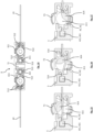
- THE figures 6 to 10 illustrate the means 6 for controlling the tension of the synchronization cables of the shutter device 1 according to a first embodiment.
- the securing means 5 are here in the form of a slider 5 mounted on the shuttles 2, 3. More particularly, the slider 5 has a fork, or groove, 51 located substantially in the middle of the slider 5.
- the fork 51 is capable of cooperating with a securing pin, or finger, 23, 33 carried by the shuttles 2, 3.
- the fork 51 allows, when the slider 5 is mounted on the shuttle 2, 3, a translation of the slider 5 relative to the shuttle 2, 3, along the Y axis.
- the slider 5 limits the friction of the synchronization cables with the shuttles and the frame of the mobile panel so as to minimize operating noise when opening and closing the mobile panel 12.
- the cursor 5 also makes it possible to reduce, or even eliminate, the distortions of the opening/closing kinematics linked to the swaying of the movable panel 12 relative to the fixed part 11 of the closing device1.
- the cursor 5 has, on each side of the fork 51, means for controlling the tension 6 of the synchronization cables 41, 42.
- the means for controlling the tension 6 of the synchronization cables 41, 42 are in the form of means for adjusting the position of the attachment point of one end of the synchronization cable in the slider 5.
- the cursor 5 has a housing 501 for receiving the means for adjusting the position of the attachment point inside the cursor 5.
- the means for adjusting the position of the attachment point inside the cursor 5 are here in the form of a tensioner 600.
- the slider 5 has a housing 501 for receiving the tensioner 600.
- the slider 5 is substantially identical on each side of the fork 51.
- the slider 5 therefore comprises two receiving housings 501 so as to receive two tensioners 600.
- Each tensioner 600 makes it possible to act on one end of a synchronization cable 41, 42.
- the receiving housing 501 has, on at least two internal lateral faces opposed, a series/plurality of teeth, or projections, of blocking 502.
- each of these side faces has four locking teeth 502 which extend towards the inside of the housing 501.
- these locking teeth 502 project substantially perpendicular to the longitudinal axis of the slider 5.
- Flexible blades 503 ensure the guidance and centering of the tensioner 600 in the direction of insertion into the receiving housing 501 of the slider 5.
- the slider 5 is able to cooperate with the tensioners 600. More precisely, the tensioners 600 make it possible to adjust the tension of the synchronization cables, whatever their length, so as to avoid a shift between the movements of the two shuttles 2, 3. The tensioners 600 make it possible to balance the tension between the two synchronization cables 41, 42 in order to optimize the synchronized movement of the shuttles 2, 3.
- Each end of the synchronization cables 41, 42 is secured to a tensioner 600 which, in cooperation with the slider 5, makes it possible to adjust the tension of the synchronization cables 41, 42.
- the tensioner 600 which is preferably a single piece, is in the form of a substantially T-shaped part in which the vertical bar 601 of the T has an internal channel 602a for passing a synchronization cable 41, 42.
- the free end of the vertical bar 601 of the T has a housing 602b for holding the head 411, 421 of the synchronization cable 41, 42.
- the head 411, 421 of the synchronization cable 41, 42 is clipped or snapped into the holding housing 602b (visible on the figures 5 And 6 in particular).
- Other solutions for securing the head 411, 421 of the synchronization cable 41, 42 are possible.
- the crossbar 605 of the T of the tensioner 600 constitutes a stop making it possible to stop/limit the insertion/introduction of the tensioner 600 into the slider 5.
- This stop 605 comprises a notch 606 for the passage of the synchronization cable 41, 42 extending in the extension of the channel 602a.
- the synchronization cable is then held firmly to the tensioner 600.
- Such a tensioner 600 allows simple and reliable assembly of the synchronization cable 41, 42.
- the tensioner 600 also has, on two opposite lateral faces of the vertical bar of the T, a series/plurality of locking notches, or hollows, 604 configured to cooperate with the locking teeth 502 formed in the receiving housing 501 of the slider 5.
- the tensioner 600 can therefore take at least two distinct positions in the receiving housing 501, so as to allow adjustment of the tension of the synchronization cable 41, 42.
- each of said faces of the tensioner 600 comprises eight locking notches 604 each corresponding to a distinct position of the tensioner 600 in the housing 501, these positions of the tensioner 600 each corresponding to a position for adjusting the tension of the synchronization cable 41, 42.
- a different number of notches can obviously be envisaged.
- the tensioner 600 can be inserted into the slider 5, as illustrated in the Figures 6 and 7 .
- the tension of the synchronization cable is therefore a function of the depth of insertion of the tensioner 600 into the housing 501 of the slider 5. Adjusting the tension of the synchronization cable 41, 42 is therefore very simple to carry out. In addition, the various locking notches 604 make it possible to obtain a relatively fine adjustment of the tension of the synchronization cable 41, 42.
- the slider 5, mounted on one of the shuttles 2, 3, makes it possible to fix one end of each synchronization cable 41, 42 to the shuttle.
- the sliders 5 and the tensioners 600 make it possible, after fixing on the shuttles 2, 3, to simply and effectively connect the shuttles together by the two synchronization cables 41, 42 and thus ensure optimal movement of the latter when opening/closing the mobile panel 12.
- the second embodiment of the proposed technique refers to the figures 11 to 22 .
- THE figures 11, 12 And 14 illustrate the means 6 for controlling the tension of the synchronization cables of the shutter device 1 according to a second embodiment.
- the securing means 5 are here in the form of a slider 5 mounted on the shuttles 2, 3. More particularly, the slider 5 has a fork, or groove, 51 located substantially in the middle of the slider 5.
- the fork 51 is capable of cooperating with a securing pin, or finger, 23, 33 carried by the shuttles 2, 3.
- the fork 51 allows, when the slider 5 is mounted on the shuttle 2, 3, a translation of the slider 5 relative to the shuttle 2, 3, along the Y axis.
- the slider 5 limits the friction of the synchronization cables with the shuttles and the frame of the mobile panel so as to minimize operating noise when opening and closing the mobile panel 12.
- the cursor 5 also makes it possible to reduce, or even eliminate, the distortions of the opening/closing kinematics linked to the swaying of the movable panel 12 relative to the fixed part 11 of the closing device1.
- the cursor 5 has, on each side of the fork 51, means for controlling the tension 6 of the synchronization cables 41, 42.
- the means for controlling the tension 6 of the synchronization cables 41, 42 are in the form of means for adjusting the length of the portion of the synchronization cable inside the slider 5.
- the cursor 5 has a housing 511 for receiving the adjustment means of the length of the portion of the synchronization cable inside the slider 5.
- the means for adjusting the length of the portion of the synchronization cable inside the slider 5 are here in the form of a tensioner 610.
- the cursor 5 has, on each side of the fork 51, a housing 511 for receiving a tensioner 610.
- the cursor 5 is substantially symmetrical on each side of the fork 51 (symmetry along the longitudinal axis of the fork).
- the receiving housing 511 is substantially cylindrical and allows the tensioner 610 to be received via the lower face of the slider 5.
- the receiving housing 511 has, on its edges, a series/plurality of locking notches, or projections, 512.
- three locking notches 512 are distributed on the edge/periphery of each receiving housing 511. These locking notches 512 extend towards the inside of the housing 511. In other words, these locking notches 512 protrude substantially perpendicular to the longitudinal axis of the receiving housing 511.
- the slider 5 has, between the fork 51 and the receiving housings 511 of the tensioners 610, a holding housing 513 of the head 411, 421 of a synchronization cable 41, 42.
- the head 411, 421 of the synchronization cable 41, 42 is clipped or snapped into a holding housing 513 (visible on the Figure 11 in particular).
- Other solutions for securing the head 411, 421 of the synchronization cable 41, 42 are possible.
- the cursor 5 also has notches 514 for passing the synchronization cable 41, 42 (visible on the figures 8 and 9 ). These notches 514 are located on either side of the receiving housing 511. More precisely, a first notch 514 is located between the receiving housing 511 of the tensioner 610 and the end edge of the slider 5, while a second notch 514 is located between the receiving housing 111 of the tensioner 610 and the receiving housing 513 of the head 411, 421 of the synchronization cable.
- the cursor 5 has an opening 516 arranged at the bottom of the receiving housing 511.
- This opening 516 has a circular central portion as well as two rectilinear portions located opposite each other, as visible in the figures 8 , 16 and 17 .
- the cursor 5 is able to cooperate with the tension means 6 which are presented, in this example, in the form of a tensioner 610.
- the slider 5 comprises two receiving housings 511 so as to receive two tensioners 610.
- Each tensioner 610 makes it possible to act on a synchronization cable 41, 42.
- the tensioners 610 allow the tension of the synchronization cables to be adjusted, regardless of their length, so as to avoid a shift between the movements of the two shuttles 2, 3.
- the tensioners 610 allow the tension between the two synchronization cables 41, 42 to be balanced in order to optimize the synchronized movement of the shuttles 2, 3.
- Each synchronization cable 41, 42 cooperates with a tensioner 610 which makes it possible to vary the routing of the latter in order to regulate/adjust the tension of the synchronization cables 41, 42.
- the tensioner 610 makes it possible to adjust the length of the portion of the synchronization cable 41, 42 received inside the slider 5.
- the tensioner 610 which is preferably a single piece, is in the form of a cylindrical wheel illustrated from different angles on the Figure 10 .
- the tensioner 610 has a first portion, or toothed wheel, 611, located on the upper part of the tensioner.
- This toothed wheel of cylindrical shape, comprises, on its periphery, a plurality of locking teeth 615 projecting perpendicular to the longitudinal axis of the wheel 610.
- An imprint 616 located on the upper face of the tensioner 610 is capable of receiving a tool (of the Allen key type in this example) allowing the tensioner 610 to be pivoted so as to adjust the tension of the synchronization cables 41, 42, as detailed below.
- the tensioner 610 has, under the toothed wheel 611 (along the Z axis), a cam 612 having a groove 618 for passing/receiving the synchronization cable.
- the cam 612 has a protrusion 614 which allows the path of the synchronization cable 41, 42 to be diverted. More precisely, this protrusion 614 allows the path/route of the synchronization cable to be extended so as to increase the tension of the latter, as detailed in more detail in relation to the figures 12 to 14 . In other words, the protrusion 614 makes it possible to adjust the length of the portion of the synchronization cable 41, 42 received inside the cursor 5.
- the cam 612 has, under the groove 618, a cylindrical portion 617 intended to cooperate with the corresponding circular portion of the opening 516 formed in the receiving housing 511 of the tensioner 610.
- the second portion 617 has a locking finger 613 intended to cooperate with the opening 516 of the slider 5 in order to lock the tensioner 610 in the receiving housing 513 provided in the slider 5.
- the locking finger 613 passes through the opening 516 of the slider 5.
- the locking of the tensioner 610 with the slider 5 is obtained by a rotation, of the quarter turn type, which is carried out when the synchronization cable 41, 42 is tensioned, that is to say when the tensioner 610 rotates.
- the locking of the tensioner 610 with the slider 5 is therefore obtained by the implementation of a locking finger and a quarter-turn rotation.
- Other solutions for locking the tensioner 610 with the slider 5 are conceivable.
- this locking can be obtained by a locking element of the clip or screw type.
- the tensioner 610 is mounted free in translation along the Z axis in the housing 511.
- it is the synchronization cable 41, 42 which, when it is tensioned, prevents the tensioner 610 from coming out of the housing 511 of the slider 5.
- the installation of the synchronization cable is carried out by introducing the head 411, 421 of the cable into the holding housing 513 of the slider then by guiding the synchronization cable into the notches 514 of the slider 5 and into the groove 618 of the tensioner 610 then by housing the tensioner 610 in its receiving housing 511.
- the synchronization cable 41, 42 is then held firmly to the slider 5 and it also cooperates with the tensioner 610.
- Such an implementation allows a simple and reliable assembly of the synchronization cable 41, 42 on the shuttle 2, 3.
- the tension of the synchronizing cable 41, 42 can then be adjusted, as illustrated in the figures 12 to 14 .
- This rotation of the tensioner 610 makes it possible to deflect/lengthen the path of the synchronization cable 41, 42. More precisely, it is the protrusion 614 which makes it possible to lengthen the path of the cable. In other words, the protrusion 614 makes it possible to adjust the length of the portion of the synchronization cable 41, 42 received inside the slider 5.
- the rotation of the tensioner 610 also allows it to be locked with the slider 5. Indeed, as described previously, this rotation allows the locking finger 613 to lock the tensioner 610 in accordance with the figures 18 to 22 .
- the locking teeth 615 of the tensioner 610 are configured to cooperate with the locking teeth 512 of the slider 5 so as to lock the position of the tensioner 610 relative to the slider 5. Rotation in the opposite direction of the tensioner 610 is therefore prevented by the cooperation of the locking teeth 512 and 615.
- the tension of the synchronization cable 41, 42 is therefore a function of the rotation of the tensioner 610. Adjusting the tension of the synchronization cable 41, 42 is therefore very simple to perform. In addition, the different locking notches 615, each corresponding to a distinct position for adjusting the cable tension, make it possible to obtain a relatively fine adjustment of the tension of the synchronization cable 41, 42.
- the slider 5, mounted on one of the shuttles 2, 3, makes it possible to fix one end of each synchronization cable 41, 42 to the shuttle.
- the sliders 5 and the tensioners 610 make it possible, after fixing on the shuttles 2, 3, to simply and effectively connect the shuttles together by the two synchronization cables 41, 42 and thus ensure optimal movement of the latter when opening/closing the mobile panel 12.
- the two embodiments of the means for controlling the tension of the synchronization cables described above have sliders respectively carrying means for adjusting the position of the attachment point of the synchronization cable in the slider and means for adjusting the length of the portion of the sync cable inside the slider.
- the means 6 for controlling the tension of the synchronization cables 41, 42 may be in the form of a return spring which makes it possible to adjust the tension of the synchronization cables. To do this, the end of the synchronization cable is connected to the return spring, itself connected to the slider 5.
- the proposed technique can be applied in the same way to other structures having a wall in which a bay is defined, such as, for example, a caravan or a motorhome.
- the bay can be formed in a side wall of the vehicle (for example for utility vehicles, MPVs, station wagons, etc.), in a wall facing the rear of the vehicle (for example for pick-ups), or even in a door.
Landscapes
- Engineering & Computer Science (AREA)
- Mechanical Engineering (AREA)
- Power-Operated Mechanisms For Wings (AREA)
- Operating, Guiding And Securing Of Roll- Type Closing Members (AREA)
Claims (13)
- Vorrichtung zum Verschließen (1) eines in eine Struktur eingelassenen Öffnungsfeldes, umfassend: einen festen Teil (11), in dem eine Öffnung definiert ist, und mindestens eine bewegliche Platte (12), die geführt entlang zweier Führungsschienen (114, 115), die auf einer Seite der festen Platte (11) montiert sind, zwischen einer Schließposition, die das Öffnungsfeld in einer ersten von der festen Platte (11) definierten Ebene, Schließebene genannt, verschließt, und mindestens einer Öffnungsposition in einer zweiten Ebene, Gleitebene genannt, die im Wesentlichen zur Schließebene parallel ist, gleitet,wobei jede der Führungsschienen (114, 115) mindestens einen in Translation in der Schiene (114, 115) geführten Schieber trägt, wobei jeder Schieber (2, 3) zwei Führungsspuren bzw. zwei feste Stifte umfasst, die geeignet sind, jeweils mit zwei festen Stiften bzw. zwei Führungsschienen zusammenzuwirken, die von einem von der beweglichen Platte (12) getragenen Rahmen getragen werden,wobei Betätigungsmittel (13) auf einen der Schieber (3) einwirken, um eine Translationsverlagerung dieser letztgenannten in den Führungsschienen (114, 115) und den Übergang der beweglichen Platte (12) von der Schließposition in die mindestens eine Gleitposition und umgekehrt zu gewährleisten, wobei zwei Synchronisierseile (41, 42) jeweils in einem der Seitenränder des Rahmens umlaufen und eine Synchronisierung der Verlagerung der Schieber (2, 3) gewährleisten,dadurch gekennzeichnet, dass jeder Schieber (2, 3) einen in Bezug zum Schieber (2, 3) beweglichen Regler (5) trägt, der ein Ende jedes der Synchronisierseile (41, 42) aufnimmt, so dass die Verlagerung der Enden der Synchronisierseile (41, 42) im Wesentlichen parallel zur Ebene der beweglichen Platte (12) bei der Verlagerung der Schieber (2, 3) ist, wobei der Übergang der beweglichen Platte (12) von der Schließposition in die mindestens eine Gleitposition und umgekehrt gewährleistet wird.
- Schließvorrichtung (1) nach Anspruch 1, dadurch gekennzeichnet, dass jeder Regler (5) gleitend in Bezug zum entsprechenden Schieber (2, 3) entlang einer im Wesentlichen auf die Verlagerungsachse der Seile senkrechten Achse geführt wird.
- Schließvorrichtung (1) nach Anspruch 1, dadurch gekennzeichnet, dass jeder Regler (5) bzw. jeder Schieber eine Gabel (51) umfasst, die mit einem Stift (23, 33) zusammenwirkt, der von dem entsprechenden Schieber (2, 3) bzw. dem entsprechenden Regler (5) getragen wird.
- Schließvorrichtung (1) nach Anspruch 1, dadurch gekennzeichnet, dass mindestens einer der Regler (5) Mittel zur Regelung der Spannung (6) mindestens eines der Synchronisierseile (41, 42) umfasst.
- Schließvorrichtung (1) nach Anspruch 4, dadurch gekennzeichnet, dass die Spannungsregelungsmittel (6) eine Rückstellfeder umfassen.
- Schließvorrichtung (1) nach Anspruch 4, dadurch gekennzeichnet, dass die Spannungsregelungsmittel (6) Mittel zur Einstellung der Position des Befestigungspunktes mindestens eines Seilendes (41, 42) in dem Regler (5) umfassen.
- Schließvorrichtung (1) nach Anspruch 6, dadurch gekennzeichnet, dass die Spannungsregelungsmittel (6) mindestens eine Spannvorrichtung (600) umfassen, die das Ende eines der Synchronisierseile (41, 42) aufnimmt und in eine Aufnahmelagerung (501) eindringt, die in dem Regler (5) ausgebildet ist, wobei die Spannvorrichtung (600) mindestens zwei unterschiedliche Positionen in der Aufnahmelagerung (501) einnehmen kann, um eine Einstellung der Spannung des entsprechenden Seils (41, 42) zu ermöglichen.
- Schließvorrichtung (1) nach Anspruch 7, dadurch gekennzeichnet, dass die Spannvorrichtung (600) mindestens eine Rastkerbe (604) aufweist, die geeignet ist, mit der Lagerung (501) zusammenzuwirken.
- Schießvorrichtung (1) nach Anspruch 8, dadurch gekennzeichnet, dass die Aufnahmelagerung (501) mindestens zwei Feststellzähne (502) aufweist, die geeignet sind, mit der oder den Rastkerben (604) der Spannvorrichtung (600) zusammenzuwirken, so dass die Einstellung der Spannung des Synchronisierseils (41, 42) von der Einsetztiefe der Spannvorrichtung (600) in der Aufnahme (501) des Reglers (5) abhängig ist.
- Schließvorrichtung (1) nach Anspruch 4, dadurch gekennzeichnet, dass die Spannungsregelungsmittel Mittel zur Einstellung der Länge des Abschnitts mindestens eines der Seile (41, 42) in dem Regler (5) umfassen.
- Schließvorrichtung nach Anspruch 10, dadurch gekennzeichnet, dass die Einstellmittel einen Nocken (612) umfassen, der je nach seiner Position einen variablen Versatz auf das Seil (41, 42) druckt.
- Schließvorrichtung nach Anspruch 11, dadurch gekennzeichnet, dass der Nocken (612) mit einem Zahnrad (611) verbunden ist, das mit mindestens zwei Rastkerben (502), die in dem Regler ausgebildet sind, zusammenwirkt und mindestens zwei Spannungseinstellungen entspricht.
- Kraftfahrzeug, umfassend mindestens eine Schließvorrichtung (1) nach einem der Ansprüche 1 bis 12.
Priority Applications (5)
| Application Number | Priority Date | Filing Date | Title |
|---|---|---|---|
| EP21188946.4A EP4124484B1 (de) | 2021-07-30 | 2021-07-30 | Vorrichtung zum verschliessen eines in die karosserie eines fahrzeugs eingelassenen öffnungsfelds und entsprechendes fahrzeug |
| KR1020247005730A KR20240039146A (ko) | 2021-07-30 | 2022-07-27 | 자동차 차체 및 대응하는 차량의 차체에 있는 개구를 차단하는 장치 |
| CN202280058414.2A CN117881557A (zh) | 2021-07-30 | 2022-07-27 | 用于封闭机动车辆的车身外壳上的孔口的装置和对应车辆 |
| PCT/EP2022/071122 WO2023006838A1 (fr) | 2021-07-30 | 2022-07-27 | Dispositif d'obturation d'une baie ménagée dans la carrosserie d'un véhicule, et véhicule correspondant |
| US18/292,947 US20250092731A1 (en) | 2021-07-30 | 2022-07-27 | Device for closing off an aperture made in the bodyshell of a motor vehicle, and corresponding vehicle |
Applications Claiming Priority (1)
| Application Number | Priority Date | Filing Date | Title |
|---|---|---|---|
| EP21188946.4A EP4124484B1 (de) | 2021-07-30 | 2021-07-30 | Vorrichtung zum verschliessen eines in die karosserie eines fahrzeugs eingelassenen öffnungsfelds und entsprechendes fahrzeug |
Publications (2)
| Publication Number | Publication Date |
|---|---|
| EP4124484A1 EP4124484A1 (de) | 2023-02-01 |
| EP4124484B1 true EP4124484B1 (de) | 2025-04-02 |
Family
ID=77168017
Family Applications (1)
| Application Number | Title | Priority Date | Filing Date |
|---|---|---|---|
| EP21188946.4A Active EP4124484B1 (de) | 2021-07-30 | 2021-07-30 | Vorrichtung zum verschliessen eines in die karosserie eines fahrzeugs eingelassenen öffnungsfelds und entsprechendes fahrzeug |
Country Status (5)
| Country | Link |
|---|---|
| US (1) | US20250092731A1 (de) |
| EP (1) | EP4124484B1 (de) |
| KR (1) | KR20240039146A (de) |
| CN (1) | CN117881557A (de) |
| WO (1) | WO2023006838A1 (de) |
Families Citing this family (1)
| Publication number | Priority date | Publication date | Assignee | Title |
|---|---|---|---|---|
| EP4311905A1 (de) * | 2022-07-27 | 2024-01-31 | Advanced Comfort Systems France SAS - ACS France | Kupplungsvorrichtung mit integrierter spielnachstellung |
Family Cites Families (19)
| Publication number | Priority date | Publication date | Assignee | Title |
|---|---|---|---|---|
| FR2742099B1 (fr) | 1995-12-08 | 1998-01-02 | Farnier & Penin | Dispositif de fermeture affleurant d'une baie de vehicule automobile |
| US5884433A (en) * | 1996-03-19 | 1999-03-23 | Mitsui Kinzoku Kogyo Kabushiki Kaisha | Tension adjusting apparatus for use in vehicle door powered sliding device |
| US5822922A (en) * | 1996-03-29 | 1998-10-20 | Excel Industries, Inc. | Power drive system for modular dual pane rear-mounted window assembly |
| FR2759408B1 (fr) | 1997-02-10 | 1999-08-27 | Farnier Et Penin Snc | Dispositif de guidage pour un panneau coulissant et louvoyant d'obturation d'une baie |
| EP1094245A3 (de) * | 1999-10-20 | 2002-04-17 | Hörmann KG Antriebstechnik | Antriebsvorrichtung mit Zugmittelgetriebe und Zugmittelspannvorrichtung sowie Zugmittelspannvorrichtung zur Verwendung darin |
| JP2006132255A (ja) * | 2004-11-09 | 2006-05-25 | Toyota Auto Body Co Ltd | 車両のスライドドア開閉装置 |
| CA2535229A1 (en) * | 2006-02-06 | 2007-08-06 | Pyramid Specialty Products Ltd. | Motorized in-line sliding window |
| KR100862719B1 (ko) * | 2007-06-08 | 2008-10-10 | 주식회사 광진엔지니어링 | 와이어식 자동차용 윈도우 레귤레이터 |
| FR2924739B1 (fr) * | 2007-12-10 | 2009-11-20 | Wagon Sas | Dispositif d'obturation d'une baie menagee dans la carrosserie d'un vehicule, a element de guidage et coulisseau formant navette, et vehicule correspondant |
| EP2277729B1 (de) | 2009-06-19 | 2014-11-19 | Advanced Comfort Systems France SAS - ACS France | Vorrichtung zum Schliessen einer in die Karosserie eines Fahrzeugs eingelassenen Öffnung mit Ausgleichsmitteln, und entsprechendes Kraftfahrzeug |
| EP2629994A1 (de) * | 2010-10-19 | 2013-08-28 | BOS GmbH & Co. KG | Antriebssystem für ein schiebedach oder einen fensterheber |
| FR2970498B1 (fr) * | 2011-01-19 | 2014-01-10 | Acs France Sas | Dispositif d'obturation d'une baie et vehicule automobile correspondant. |
| US8813425B2 (en) * | 2012-03-27 | 2014-08-26 | Pilkington Group Limited | Movable panel assembly with a power sliding drive mechanism |
| JP6801670B2 (ja) * | 2015-12-16 | 2020-12-16 | Agc株式会社 | 窓用装置 |
| US10518611B2 (en) * | 2016-09-09 | 2019-12-31 | Yachiyo Industry Co., Ltd. | Power slide window |
| WO2020026768A1 (ja) * | 2018-07-31 | 2020-02-06 | 八千代工業株式会社 | パワースライドウィンドウ |
| FR3094999B1 (fr) * | 2019-04-10 | 2021-06-25 | Somfy Activites Sa | Dispositif d’entraînement motorisé, fenêtre coulissante pour un bâtiment et installation domotique associées |
| KR102846953B1 (ko) * | 2020-10-15 | 2025-08-14 | 현대자동차주식회사 | 슬라이딩 도어의 유동 방지 구조 |
| EP4223568A1 (de) * | 2022-02-03 | 2023-08-09 | Advanced Comfort Systems France SAS - ACS France | Vorrichtung zur abdichtung eines in die karosserie eines fahrzeugs eingelassenen öffnungsfelds und entsprechendes fahrzeug |
-
2021
- 2021-07-30 EP EP21188946.4A patent/EP4124484B1/de active Active
-
2022
- 2022-07-27 KR KR1020247005730A patent/KR20240039146A/ko active Pending
- 2022-07-27 US US18/292,947 patent/US20250092731A1/en active Pending
- 2022-07-27 WO PCT/EP2022/071122 patent/WO2023006838A1/fr not_active Ceased
- 2022-07-27 CN CN202280058414.2A patent/CN117881557A/zh active Pending
Also Published As
| Publication number | Publication date |
|---|---|
| KR20240039146A (ko) | 2024-03-26 |
| EP4124484A1 (de) | 2023-02-01 |
| CN117881557A (zh) | 2024-04-12 |
| US20250092731A1 (en) | 2025-03-20 |
| WO2023006838A1 (fr) | 2023-02-02 |
Similar Documents
| Publication | Publication Date | Title |
|---|---|---|
| EP2442993B1 (de) | Vorrichtung zum schliessen einer in die karosserie eines fahrzeugs eingelassenen öffnung mit ausgleichsmitteln, und entsprechendes kraftfahrzeug | |
| EP4124484B1 (de) | Vorrichtung zum verschliessen eines in die karosserie eines fahrzeugs eingelassenen öffnungsfelds und entsprechendes fahrzeug | |
| EP3830369B1 (de) | Vorrichtung zum führen einer fahrzeugtür | |
| EP3967531B1 (de) | Vorrichtung zur abdichtung eines in die karosserie eines fahrzeugs eingelassenen öffnungsfelds, und entsprechendes fahrzeug | |
| EP3027446B1 (de) | Schliessvorrichtung für ein fahrzeugdach mit einer beweglichen platte und einem drehbaren hebel, sowie entsprechendes fahrzeug | |
| EP1880885B1 (de) | Abdeckungsvorrichtung mit Verriegelungsmitteln für ein Kraftfahrzeug | |
| EP4472852A1 (de) | Vorrichtung zum verschliessen einer öffnung in der karosserie eines fahrzeugs und entsprechendes fahrzeug | |
| EP1921234A1 (de) | Verriegelungsvorrichtung mit deformierbarem Griff für Schiebeflügel, entsprechende Abdeckvorrichtung und entsprechendes Kraftfahrzeug | |
| FR2833209A1 (fr) | Dispositif d'obturation d'une baie menagee dans la carrosserie d'un vehicule, et vehicule correspondant | |
| WO2023147865A1 (fr) | Dispositif d'obturation d'une baie menagee dans la carrosserie d'un vehicule, et vehicule correspondant | |
| FR2833212A1 (fr) | Dispositif d'obturation d'une baie menagee dans un vehicule a rail de coulissement unique, et vehicule correspondant | |
| FR2882090A1 (fr) | Dispositif d'occultation a rideau enrouleur manuel et multi position | |
| EP1433633B1 (de) | Schliesseinrichtung einer Öffnung in einem Fahrzeug und zugehöriges Fahrzeug | |
| EP1916364A1 (de) | Verriegelungsvorrichtung mit Zahnstange für Schiebepaneel eines Kraftfahrzeugs, entsprechende Verschlussvorrichtung und entsprechendes Kraftfahrzeug | |
| EP1323558B1 (de) | Motorisch betriebene Schliesseinrichtung einer Öffnung in einem Fahrzeug und zugehöriges Fahrzeug | |
| EP1407909B1 (de) | Schliesseinrichtung für eine in einer Kraftfahrzeugkarrosserie angeordnete Öffnung mit einem beweglichen und verschwenkbaren Deckel | |
| FR3114118A1 (fr) | Dispositif de commande d'ouverture pour une porte d'un véhicule automobile. | |
| EP3560741B1 (de) | Vorrichtung zur abdichtung eines in die karosserie eines fahrzeugs eingelassenen öffnungsfelds, und entsprechendes fahrzeug | |
| EP3350016B1 (de) | Verriegelungsvorrichtung für zwei positionen einer hintersitz-rückenlehne eines kraftfahrzeugs | |
| FR2893074A1 (fr) | Porte de vehicule automobile a panneau vitre coulissant, et vehicule correspondant. | |
| FR2833210A1 (fr) | Dispositif d'obturation d'une baie menagee dans un vehicule, a panneau mobile en rotation, et vehicule correspondant | |
| FR2833213A1 (fr) | Dispositif d'obturation d'une baie menagee dans un vehicule a rail de coulissement unique, et vehicule correspondant | |
| WO2024023255A1 (fr) | Dispositif d'obturation | |
| WO2024246012A1 (fr) | Dispositif d'obturation d'une baie à rail étagé, et véhicule correspondant | |
| FR3149239A1 (fr) | Dispositif d'obturation d'une baie à rail étagé, et véhicule correspondant. |
Legal Events
| Date | Code | Title | Description |
|---|---|---|---|
| PUAI | Public reference made under article 153(3) epc to a published international application that has entered the european phase |
Free format text: ORIGINAL CODE: 0009012 |
|
| STAA | Information on the status of an ep patent application or granted ep patent |
Free format text: STATUS: THE APPLICATION HAS BEEN PUBLISHED |
|
| AK | Designated contracting states |
Kind code of ref document: A1 Designated state(s): AL AT BE BG CH CY CZ DE DK EE ES FI FR GB GR HR HU IE IS IT LI LT LU LV MC MK MT NL NO PL PT RO RS SE SI SK SM TR |
|
| P01 | Opt-out of the competence of the unified patent court (upc) registered |
Effective date: 20230527 |
|
| STAA | Information on the status of an ep patent application or granted ep patent |
Free format text: STATUS: REQUEST FOR EXAMINATION WAS MADE |
|
| 17P | Request for examination filed |
Effective date: 20230719 |
|
| RBV | Designated contracting states (corrected) |
Designated state(s): AL AT BE BG CH CY CZ DE DK EE ES FI FR GB GR HR HU IE IS IT LI LT LU LV MC MK MT NL NO PL PT RO RS SE SI SK SM TR |
|
| GRAJ | Information related to disapproval of communication of intention to grant by the applicant or resumption of examination proceedings by the epo deleted |
Free format text: ORIGINAL CODE: EPIDOSDIGR1 |
|
| GRAP | Despatch of communication of intention to grant a patent |
Free format text: ORIGINAL CODE: EPIDOSNIGR1 |
|
| GRAP | Despatch of communication of intention to grant a patent |
Free format text: ORIGINAL CODE: EPIDOSNIGR1 |
|
| STAA | Information on the status of an ep patent application or granted ep patent |
Free format text: STATUS: GRANT OF PATENT IS INTENDED |
|
| INTG | Intention to grant announced |
Effective date: 20240515 |
|
| GRAJ | Information related to disapproval of communication of intention to grant by the applicant or resumption of examination proceedings by the epo deleted |
Free format text: ORIGINAL CODE: EPIDOSDIGR1 |
|
| STAA | Information on the status of an ep patent application or granted ep patent |
Free format text: STATUS: REQUEST FOR EXAMINATION WAS MADE |
|
| INTC | Intention to grant announced (deleted) | ||
| GRAP | Despatch of communication of intention to grant a patent |
Free format text: ORIGINAL CODE: EPIDOSNIGR1 |
|
| STAA | Information on the status of an ep patent application or granted ep patent |
Free format text: STATUS: GRANT OF PATENT IS INTENDED |
|
| INTG | Intention to grant announced |
Effective date: 20241104 |
|
| GRAS | Grant fee paid |
Free format text: ORIGINAL CODE: EPIDOSNIGR3 |
|
| GRAA | (expected) grant |
Free format text: ORIGINAL CODE: 0009210 |
|
| STAA | Information on the status of an ep patent application or granted ep patent |
Free format text: STATUS: THE PATENT HAS BEEN GRANTED |
|
| AK | Designated contracting states |
Kind code of ref document: B1 Designated state(s): AL AT BE BG CH CY CZ DE DK EE ES FI FR GB GR HR HU IE IS IT LI LT LU LV MC MK MT NL NO PL PT RO RS SE SI SK SM TR |
|
| REG | Reference to a national code |
Ref country code: GB Ref legal event code: FG4D Free format text: NOT ENGLISH |
|
| REG | Reference to a national code |
Ref country code: CH Ref legal event code: EP |
|
| REG | Reference to a national code |
Ref country code: DE Ref legal event code: R096 Ref document number: 602021028414 Country of ref document: DE |
|
| REG | Reference to a national code |
Ref country code: IE Ref legal event code: FG4D Free format text: LANGUAGE OF EP DOCUMENT: FRENCH |
|
| REG | Reference to a national code |
Ref country code: NL Ref legal event code: MP Effective date: 20250402 |
|
| PG25 | Lapsed in a contracting state [announced via postgrant information from national office to epo] |
Ref country code: NL Free format text: LAPSE BECAUSE OF FAILURE TO SUBMIT A TRANSLATION OF THE DESCRIPTION OR TO PAY THE FEE WITHIN THE PRESCRIBED TIME-LIMIT Effective date: 20250402 |
|
| REG | Reference to a national code |
Ref country code: AT Ref legal event code: MK05 Ref document number: 1780969 Country of ref document: AT Kind code of ref document: T Effective date: 20250402 |
|
| PG25 | Lapsed in a contracting state [announced via postgrant information from national office to epo] |
Ref country code: FI Free format text: LAPSE BECAUSE OF FAILURE TO SUBMIT A TRANSLATION OF THE DESCRIPTION OR TO PAY THE FEE WITHIN THE PRESCRIBED TIME-LIMIT Effective date: 20250402 Ref country code: ES Free format text: LAPSE BECAUSE OF FAILURE TO SUBMIT A TRANSLATION OF THE DESCRIPTION OR TO PAY THE FEE WITHIN THE PRESCRIBED TIME-LIMIT Effective date: 20250402 Ref country code: PT Free format text: LAPSE BECAUSE OF FAILURE TO SUBMIT A TRANSLATION OF THE DESCRIPTION OR TO PAY THE FEE WITHIN THE PRESCRIBED TIME-LIMIT Effective date: 20250804 |
|
| PGFP | Annual fee paid to national office [announced via postgrant information from national office to epo] |
Ref country code: DE Payment date: 20250722 Year of fee payment: 5 |
|
| REG | Reference to a national code |
Ref country code: LT Ref legal event code: MG9D |
|
| PG25 | Lapsed in a contracting state [announced via postgrant information from national office to epo] |
Ref country code: NO Free format text: LAPSE BECAUSE OF FAILURE TO SUBMIT A TRANSLATION OF THE DESCRIPTION OR TO PAY THE FEE WITHIN THE PRESCRIBED TIME-LIMIT Effective date: 20250702 |
|
| PG25 | Lapsed in a contracting state [announced via postgrant information from national office to epo] |
Ref country code: PL Free format text: LAPSE BECAUSE OF FAILURE TO SUBMIT A TRANSLATION OF THE DESCRIPTION OR TO PAY THE FEE WITHIN THE PRESCRIBED TIME-LIMIT Effective date: 20250402 |
|
| PG25 | Lapsed in a contracting state [announced via postgrant information from national office to epo] |
Ref country code: BG Free format text: LAPSE BECAUSE OF FAILURE TO SUBMIT A TRANSLATION OF THE DESCRIPTION OR TO PAY THE FEE WITHIN THE PRESCRIBED TIME-LIMIT Effective date: 20250402 |
|
| PGFP | Annual fee paid to national office [announced via postgrant information from national office to epo] |
Ref country code: BE Payment date: 20250721 Year of fee payment: 5 |
|
| PG25 | Lapsed in a contracting state [announced via postgrant information from national office to epo] |
Ref country code: HR Free format text: LAPSE BECAUSE OF FAILURE TO SUBMIT A TRANSLATION OF THE DESCRIPTION OR TO PAY THE FEE WITHIN THE PRESCRIBED TIME-LIMIT Effective date: 20250402 |
|
| PG25 | Lapsed in a contracting state [announced via postgrant information from national office to epo] |
Ref country code: AT Free format text: LAPSE BECAUSE OF FAILURE TO SUBMIT A TRANSLATION OF THE DESCRIPTION OR TO PAY THE FEE WITHIN THE PRESCRIBED TIME-LIMIT Effective date: 20250402 |
|
| PGFP | Annual fee paid to national office [announced via postgrant information from national office to epo] |
Ref country code: FR Payment date: 20250724 Year of fee payment: 5 |
|
| PG25 | Lapsed in a contracting state [announced via postgrant information from national office to epo] |
Ref country code: RS Free format text: LAPSE BECAUSE OF FAILURE TO SUBMIT A TRANSLATION OF THE DESCRIPTION OR TO PAY THE FEE WITHIN THE PRESCRIBED TIME-LIMIT Effective date: 20250702 |
|
| PG25 | Lapsed in a contracting state [announced via postgrant information from national office to epo] |
Ref country code: IS Free format text: LAPSE BECAUSE OF FAILURE TO SUBMIT A TRANSLATION OF THE DESCRIPTION OR TO PAY THE FEE WITHIN THE PRESCRIBED TIME-LIMIT Effective date: 20250802 |
|
| PG25 | Lapsed in a contracting state [announced via postgrant information from national office to epo] |
Ref country code: LV Free format text: LAPSE BECAUSE OF FAILURE TO SUBMIT A TRANSLATION OF THE DESCRIPTION OR TO PAY THE FEE WITHIN THE PRESCRIBED TIME-LIMIT Effective date: 20250402 |
|
| PG25 | Lapsed in a contracting state [announced via postgrant information from national office to epo] |
Ref country code: SM Free format text: LAPSE BECAUSE OF FAILURE TO SUBMIT A TRANSLATION OF THE DESCRIPTION OR TO PAY THE FEE WITHIN THE PRESCRIBED TIME-LIMIT Effective date: 20250402 Ref country code: DK Free format text: LAPSE BECAUSE OF FAILURE TO SUBMIT A TRANSLATION OF THE DESCRIPTION OR TO PAY THE FEE WITHIN THE PRESCRIBED TIME-LIMIT Effective date: 20250402 |
|
| PG25 | Lapsed in a contracting state [announced via postgrant information from national office to epo] |
Ref country code: CZ Free format text: LAPSE BECAUSE OF FAILURE TO SUBMIT A TRANSLATION OF THE DESCRIPTION OR TO PAY THE FEE WITHIN THE PRESCRIBED TIME-LIMIT Effective date: 20250402 |
|
| PG25 | Lapsed in a contracting state [announced via postgrant information from national office to epo] |
Ref country code: EE Free format text: LAPSE BECAUSE OF FAILURE TO SUBMIT A TRANSLATION OF THE DESCRIPTION OR TO PAY THE FEE WITHIN THE PRESCRIBED TIME-LIMIT Effective date: 20250402 |
|
| PG25 | Lapsed in a contracting state [announced via postgrant information from national office to epo] |
Ref country code: SK Free format text: LAPSE BECAUSE OF FAILURE TO SUBMIT A TRANSLATION OF THE DESCRIPTION OR TO PAY THE FEE WITHIN THE PRESCRIBED TIME-LIMIT Effective date: 20250402 |
|
| PG25 | Lapsed in a contracting state [announced via postgrant information from national office to epo] |
Ref country code: IT Free format text: LAPSE BECAUSE OF FAILURE TO SUBMIT A TRANSLATION OF THE DESCRIPTION OR TO PAY THE FEE WITHIN THE PRESCRIBED TIME-LIMIT Effective date: 20250402 |
|
| PLBE | No opposition filed within time limit |
Free format text: ORIGINAL CODE: 0009261 |
|
| STAA | Information on the status of an ep patent application or granted ep patent |
Free format text: STATUS: NO OPPOSITION FILED WITHIN TIME LIMIT |
|
| PG25 | Lapsed in a contracting state [announced via postgrant information from national office to epo] |
Ref country code: RO Free format text: LAPSE BECAUSE OF FAILURE TO SUBMIT A TRANSLATION OF THE DESCRIPTION OR TO PAY THE FEE WITHIN THE PRESCRIBED TIME-LIMIT Effective date: 20250402 |
|
| REG | Reference to a national code |
Ref country code: CH Ref legal event code: L10 Free format text: ST27 STATUS EVENT CODE: U-0-0-L10-L00 (AS PROVIDED BY THE NATIONAL OFFICE) Effective date: 20260211 |