EP4124471B1 - Reifen - Google Patents
Reifen Download PDFInfo
- Publication number
- EP4124471B1 EP4124471B1 EP22182948.4A EP22182948A EP4124471B1 EP 4124471 B1 EP4124471 B1 EP 4124471B1 EP 22182948 A EP22182948 A EP 22182948A EP 4124471 B1 EP4124471 B1 EP 4124471B1
- Authority
- EP
- European Patent Office
- Prior art keywords
- tire
- cord
- belt
- band
- ply
- Prior art date
- Legal status (The legal status is an assumption and is not a legal conclusion. Google has not performed a legal analysis and makes no representation as to the accuracy of the status listed.)
- Active
Links
Images


Classifications
-
- B—PERFORMING OPERATIONS; TRANSPORTING
- B60—VEHICLES IN GENERAL
- B60C—VEHICLE TYRES; TYRE INFLATION; TYRE CHANGING; CONNECTING VALVES TO INFLATABLE ELASTIC BODIES IN GENERAL; DEVICES OR ARRANGEMENTS RELATED TO TYRES
- B60C9/00—Reinforcements or ply arrangement of pneumatic tyres
- B60C9/18—Structure or arrangement of belts or breakers, crown-reinforcing or cushioning layers
- B60C9/20—Structure or arrangement of belts or breakers, crown-reinforcing or cushioning layers built-up from rubberised plies each having all cords arranged substantially parallel
- B60C9/2003—Structure or arrangement of belts or breakers, crown-reinforcing or cushioning layers built-up from rubberised plies each having all cords arranged substantially parallel characterised by the materials of the belt cords
- B60C9/2009—Structure or arrangement of belts or breakers, crown-reinforcing or cushioning layers built-up from rubberised plies each having all cords arranged substantially parallel characterised by the materials of the belt cords comprising plies of different materials
-
- B—PERFORMING OPERATIONS; TRANSPORTING
- B60—VEHICLES IN GENERAL
- B60C—VEHICLE TYRES; TYRE INFLATION; TYRE CHANGING; CONNECTING VALVES TO INFLATABLE ELASTIC BODIES IN GENERAL; DEVICES OR ARRANGEMENTS RELATED TO TYRES
- B60C9/00—Reinforcements or ply arrangement of pneumatic tyres
- B60C9/18—Structure or arrangement of belts or breakers, crown-reinforcing or cushioning layers
- B60C9/20—Structure or arrangement of belts or breakers, crown-reinforcing or cushioning layers built-up from rubberised plies each having all cords arranged substantially parallel
- B60C2009/2061—Physical properties or dimensions of the belt coating rubber
- B60C2009/2067—Thickness
-
- B—PERFORMING OPERATIONS; TRANSPORTING
- B60—VEHICLES IN GENERAL
- B60C—VEHICLE TYRES; TYRE INFLATION; TYRE CHANGING; CONNECTING VALVES TO INFLATABLE ELASTIC BODIES IN GENERAL; DEVICES OR ARRANGEMENTS RELATED TO TYRES
- B60C9/00—Reinforcements or ply arrangement of pneumatic tyres
- B60C9/18—Structure or arrangement of belts or breakers, crown-reinforcing or cushioning layers
- B60C9/20—Structure or arrangement of belts or breakers, crown-reinforcing or cushioning layers built-up from rubberised plies each having all cords arranged substantially parallel
- B60C2009/2074—Physical properties or dimension of the belt cord
- B60C2009/2077—Diameters of the cords; Linear density thereof
-
- B—PERFORMING OPERATIONS; TRANSPORTING
- B60—VEHICLES IN GENERAL
- B60C—VEHICLE TYRES; TYRE INFLATION; TYRE CHANGING; CONNECTING VALVES TO INFLATABLE ELASTIC BODIES IN GENERAL; DEVICES OR ARRANGEMENTS RELATED TO TYRES
- B60C9/00—Reinforcements or ply arrangement of pneumatic tyres
- B60C9/18—Structure or arrangement of belts or breakers, crown-reinforcing or cushioning layers
- B60C9/20—Structure or arrangement of belts or breakers, crown-reinforcing or cushioning layers built-up from rubberised plies each having all cords arranged substantially parallel
- B60C2009/2074—Physical properties or dimension of the belt cord
- B60C2009/2083—Density in width direction
-
- B—PERFORMING OPERATIONS; TRANSPORTING
- B60—VEHICLES IN GENERAL
- B60C—VEHICLE TYRES; TYRE INFLATION; TYRE CHANGING; CONNECTING VALVES TO INFLATABLE ELASTIC BODIES IN GENERAL; DEVICES OR ARRANGEMENTS RELATED TO TYRES
- B60C9/00—Reinforcements or ply arrangement of pneumatic tyres
- B60C9/18—Structure or arrangement of belts or breakers, crown-reinforcing or cushioning layers
- B60C9/20—Structure or arrangement of belts or breakers, crown-reinforcing or cushioning layers built-up from rubberised plies each having all cords arranged substantially parallel
- B60C9/22—Structure or arrangement of belts or breakers, crown-reinforcing or cushioning layers built-up from rubberised plies each having all cords arranged substantially parallel the plies being arranged with all cords disposed along the circumference of the tyre
- B60C2009/2238—Physical properties or dimensions of the ply coating rubber
- B60C2009/2247—Thickness
-
- B—PERFORMING OPERATIONS; TRANSPORTING
- B60—VEHICLES IN GENERAL
- B60C—VEHICLE TYRES; TYRE INFLATION; TYRE CHANGING; CONNECTING VALVES TO INFLATABLE ELASTIC BODIES IN GENERAL; DEVICES OR ARRANGEMENTS RELATED TO TYRES
- B60C9/00—Reinforcements or ply arrangement of pneumatic tyres
- B60C9/18—Structure or arrangement of belts or breakers, crown-reinforcing or cushioning layers
- B60C9/20—Structure or arrangement of belts or breakers, crown-reinforcing or cushioning layers built-up from rubberised plies each having all cords arranged substantially parallel
- B60C9/22—Structure or arrangement of belts or breakers, crown-reinforcing or cushioning layers built-up from rubberised plies each having all cords arranged substantially parallel the plies being arranged with all cords disposed along the circumference of the tyre
- B60C2009/2252—Physical properties or dimension of the zero degree ply cords
- B60C2009/2257—Diameters of the cords; Linear density thereof
-
- B—PERFORMING OPERATIONS; TRANSPORTING
- B60—VEHICLES IN GENERAL
- B60C—VEHICLE TYRES; TYRE INFLATION; TYRE CHANGING; CONNECTING VALVES TO INFLATABLE ELASTIC BODIES IN GENERAL; DEVICES OR ARRANGEMENTS RELATED TO TYRES
- B60C9/00—Reinforcements or ply arrangement of pneumatic tyres
- B60C9/18—Structure or arrangement of belts or breakers, crown-reinforcing or cushioning layers
- B60C9/20—Structure or arrangement of belts or breakers, crown-reinforcing or cushioning layers built-up from rubberised plies each having all cords arranged substantially parallel
- B60C9/22—Structure or arrangement of belts or breakers, crown-reinforcing or cushioning layers built-up from rubberised plies each having all cords arranged substantially parallel the plies being arranged with all cords disposed along the circumference of the tyre
- B60C2009/2252—Physical properties or dimension of the zero degree ply cords
- B60C2009/2266—Density of the cords in width direction
-
- B—PERFORMING OPERATIONS; TRANSPORTING
- B60—VEHICLES IN GENERAL
- B60C—VEHICLE TYRES; TYRE INFLATION; TYRE CHANGING; CONNECTING VALVES TO INFLATABLE ELASTIC BODIES IN GENERAL; DEVICES OR ARRANGEMENTS RELATED TO TYRES
- B60C9/00—Reinforcements or ply arrangement of pneumatic tyres
- B60C9/0064—Reinforcements comprising monofilaments
-
- B—PERFORMING OPERATIONS; TRANSPORTING
- B60—VEHICLES IN GENERAL
- B60C—VEHICLE TYRES; TYRE INFLATION; TYRE CHANGING; CONNECTING VALVES TO INFLATABLE ELASTIC BODIES IN GENERAL; DEVICES OR ARRANGEMENTS RELATED TO TYRES
- B60C9/00—Reinforcements or ply arrangement of pneumatic tyres
- B60C9/18—Structure or arrangement of belts or breakers, crown-reinforcing or cushioning layers
- B60C9/20—Structure or arrangement of belts or breakers, crown-reinforcing or cushioning layers built-up from rubberised plies each having all cords arranged substantially parallel
- B60C9/22—Structure or arrangement of belts or breakers, crown-reinforcing or cushioning layers built-up from rubberised plies each having all cords arranged substantially parallel the plies being arranged with all cords disposed along the circumference of the tyre
-
- Y—GENERAL TAGGING OF NEW TECHNOLOGICAL DEVELOPMENTS; GENERAL TAGGING OF CROSS-SECTIONAL TECHNOLOGIES SPANNING OVER SEVERAL SECTIONS OF THE IPC; TECHNICAL SUBJECTS COVERED BY FORMER USPC CROSS-REFERENCE ART COLLECTIONS [XRACs] AND DIGESTS
- Y02—TECHNOLOGIES OR APPLICATIONS FOR MITIGATION OR ADAPTATION AGAINST CLIMATE CHANGE
- Y02T—CLIMATE CHANGE MITIGATION TECHNOLOGIES RELATED TO TRANSPORTATION
- Y02T10/00—Road transport of goods or passengers
- Y02T10/80—Technologies aiming to reduce greenhouse gasses emissions common to all road transportation technologies
- Y02T10/86—Optimisation of rolling resistance, e.g. weight reduction
Definitions
- the present invention relates to a tire having a belt layer and a band layer.
- Japanese Laid-Open Patent Publication No. 2019-177838 suggests a tire in which a belt formed of two or more layers includes cords, and a gauge between the cords of the two adjacent layers is specified to allow achievement of both noise performance and fuel economy.
- the present invention has been made in view of the aforementioned circumstances, and a main object of the present invention is to provide a tire that can achieve both durability and ride comfort during high-speed running.
- the tire of the present invention has the belt layer and the band layer having such structures and thus can allow achievement of both durability and ride comfort during high-speed running.
- the "normal internal pressure” represents an air pressure that is defined for each tire by the standard, and is “maximum air pressure” in the JATMA standard, the maximum value recited in the table “TIRE LOAD LIMITS AT VARIOUS COLD INFLATION PRESSURES" in the TRA standard, or "INFLATION PRESSURE” in the ETRTO standard.
- the "normal internal pressure” is 250 kPa for tires for passenger cars.
- the tire for a passenger car is not particularly limited as long as the normal load is not higher than 1000 kg. However, from the viewpoint of reducing excessive deformation at a tread portion, the tire for a passenger car is preferably applied to a tire for which the normal load is 900 kg, more preferably applied to a tire for which the normal load is 750 kg, and even more preferably applied to a tire for which the normal load is 700 kg.
- the "normal load” represents a load that is defined by a standard, in a standard system including the standard on which the tire 1 is based, for each tire, and is the "maximum load capacity" in the JATMA standard, the maximum value recited in the table "TIRE LOAD LIMITS AT VARIOUS COLD INFLATION PRESSURES" in the TRA standard, or the "LOAD CAPACITY" in the ETRTO standard.
- the tire 1 is not limited to a tire for a passenger car, and can be applied to, for example, a heavy-duty tire, a tire for a motorcycle, a tire for a racing vehicle, and the like.
- the tire 1 having a belt layer 7 and a band layer 9 described below can be applied to various tires including, for example, non-pneumatic tires the insides of which are not filled with pressurized air.
- an outer surface 2a forms a ground contact surface that comes into contact with a road surface during running.
- the profile of the outer surface 2a of the tread portion 2 is formed by, for example, a single arc or a combination of arcs having a plurality of curvatures on the tire meridian cross-section.
- circumferential grooves extending in the tire circumferential direction for example, circumferential grooves extending in the tire circumferential direction, lateral grooves extending in the tire axial direction, sipes each having a groove width of not greater than 2 mm, and the like may be disposed as appropriate.
- the circumferential grooves include grooves that linearly extend and grooves extending so as to zigzag.
- the elastomer layer of the tread portion 2 is formed of, for example, isoprene-based rubber such as natural rubber and isoprene rubber, diene-based rubber such as butadiene rubber, styrene-butadiene rubber, styrene-isoprene-butadiene rubber, chloroprene rubber, acrylonitrile butadiene rubber, and isobutylene-isoprene-rubber, or a thermoplastic elastomer such as styrene-butadiene block copolymers and styrene-isoprene-styrene copolymers.
- the diene-based rubber is preferably used for the elastomer layer of the tread portion 2.
- a boundary face between the elastomer layer of the tread portion 2 and the elastomer layer of the sidewall portion 3 is, for example, formed such that the tire-axially outer end is disposed outward of the tire-axially inner end in the tire radial direction a.
- the boundary face between the elastomer layer of the tread portion 2 and the elastomer layer of the sidewall portion 3 may be, for example, formed such that the tire-axially outer end is disposed inward of the tire-axially inner end in the tire radial direction a.
- the carcass 6 includes at least one carcass ply 6A.
- the carcass 6 includes one carcass ply 6A.
- the carcass ply 6A is formed of, for example, an elastomer layer including a carcass cord (not shown) disposed at an angle of 75° to 90° relative to the tire circumferential direction.
- a carcass cord for example, an organic fiber cord formed of aromatic polyamide (aramid), rayon, polyester, or the like can be adopted.
- aromatic polyamide rayon, polyester, or the like
- the carcass ply 6A includes, for example, a body portion 6a extending from the tread portion 2 through the sidewall portions 3 to the bead cores 5 of the bead portions 4, and turned-up portions 6b that are continuous with the body portion 6a and are turned up around the bead cores 5 from the inner side toward the outer side in the tire axial direction.
- an outer end of the turned-up portion 6b in the tire radial direction may extend to the belt layer 7.
- a bead apex 8 is disposed between the body portion 6a and each turned-up portion 6b of the carcass ply 6A so as to extend outwardly from the bead core 5 in the tire radial direction.
- the bead apex 8 is formed of, for example, an elastomer layer.
- chafers may be disposed outward of the turned-up portions 6b of the carcass 6 in the tire axial direction.
- the chafer is preferably disposed outward of the bead reinforcing layer in the tire axial direction.
- the belt cord 7a is a plated or ternary alloy-plated one.
- the plating treatment for example, plating treatment using zinc, copper, and the like can be performed.
- the ternary alloy-plating treatment for example, ternary alloy-plating treatment using zinc, copper, cobalt, and the like can be performed.
- a gauge s representing a distance in the tire radial direction between a surface of the belt cord 7a of the belt ply 7B and the surface, of the band cord 9a of the band ply 9A, adjacent to the surface of the belt cord 7a in the tire radial direction is 0.1 to 0.3 mm.
- the gauge s between the belt cord 7a and the band cord 9a is small, so that a centrifugal force acting on the tread portion 2 during high-speed running can be reduced, and durability of the tire 1 during high-speed running can be enhanced. This may be because a centrifugal force acting on the tread portion 2 can be reduced, and deformation of the tread portion 2 is reduced, and, consequently, heat generation is inhibited.
- the mechanism for allowing the effect of the present embodiment to be exhibited may be as follows, but is not necessarily intended to be limited to the following theory.
- the tire 1 of the present embodiment is considered to achieve ride comfort during high-speed running while enhancing durability during high-speed running.
- the belt cord 7a and the band cord 9a each have a round cross-section.
- the belt cord 7a and the band cord 9a each have a flattened cross-section.
- the round means that a ratio between a major axis and a minor axis on the cross-section is less than 1.05.
- the flattened means that a ratio between a major axis and a minor axis on the cross-section is not less than 1.05.
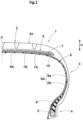
- the diameter d1, in the tire radial direction a, of the belt cord 7a represents, for example, a diameter of a cross section, for the belt cord 7a having a round cross-section as shown in FIG. 2 .
- the diameter d1, in the tire radial direction a, of the belt cord 7a represents a dimension along the tire radial direction a, for the belt cord 7a having a flattened cross-section as shown in FIG. 3 .
- FIG. 4 is a schematic diagram illustrating the belt cord 7a.
- the belt cord 7a having a flattened cross-section is inclined relative to the tire radial direction a
- one axis, of the minor axis Sd and the major axis Ld of the belt cord 7a having the flattened cross-section, having a smaller angle relative to the tire radial direction a is defined as the diameter d1 in the tire radial direction a.
- an angle ⁇ 1 of the minor axis Sd direction relative to the tire radial direction a is less than an angle ⁇ 2 of the major axis Ld direction relative thereto, and, therefore, the minor axis Sd is defined as the diameter d1 in the tire radial direction a.
- the diameter d2, in the tire radial direction a, of the band cord 9a represents, for example, a diameter of the cross-section, for the band cord 9a having a round cross-section as shown in FIG. 2 .
- the diameter d2, in the tire radial direction a, of the band cord 9a represents, for example, a dimension along the tire radial direction a, for the band cord 9a having a flattened cross-section as shown in FIG. 3 .
- one axis, of the minor axis and the major axis of the band cord 9a having the flattened cross-section, having a smaller angle relative to the tire radial direction a is defined as the diameter d2 in the tire radial direction a (refer to FIG. 4 ), which is not shown.
- the diameter d1, in the tire radial direction a, of the belt cord 7a is preferably 0.16 to 0.42 mm.
- the belt cord 7a having such a structure can reduce a centrifugal force acting on the tread portion 2 during high-speed running since the diameter d1, in the tire radial direction a, of the belt cord 7a is small, and can allow achievement of both durability of the tire 1 and ride comfort exhibited by the tire 1 during high-speed running.
- the diameter d1 of the belt cord 7a is not greater than 0.42 mm, enhancement of bending stiffness is inhibited, and ride comfort exhibited by the tire 1 during high-speed running can be enhanced. From such a viewpoint, the diameter d1 of the belt cord 7a is more preferably not greater than 0.38 mm and even more preferably not greater than 0.35 mm.
- the belt cords 7a are arranged per ply width of 5 cm in each of the belt plies 7A, 7B.
- the number n1 of the belt cords 7a arranged per ply width of 5 cm represents the number of the belt cords 7a arranged per ply width of 5 cm in the direction orthogonal to the longitudinal direction of the belt cord 7a.
- the number n1 of the arranged belt cords 7a can be, for example, obtained by measurement in a range of the belt ply 7A, 7B including the tire equator C.
- the number n1 of the belt cords 7a arranged per ply width of 5 cm is not less than 50, stiffness of the tread portion 2 in the tire axial direction can be enhanced, and durability of the tire 1 during high-speed running can be enhanced. From such a viewpoint, the number n1 of the arranged the belt cords 7a is more preferably not less than 60 and even more preferably not less than 70.
- the number n1 of the belt cords 7a arranged per ply width of 5 cm is not greater than 200, stiffness of the tread portion 2 is inhibited from being excessively enhanced, and ride comfort exhibited by the tire 1 during high-speed running can be enhanced.
- the number n1 of the arranged the belt cords 7a is more preferably not greater than 190 and even more preferably not greater than 180.
- the product (d1 ⁇ n1) is not less than 38, holdability of the tread portion 2 is enhanced and durability of the tire 1 during high-speed running can be enhanced. From such a viewpoint, the product (d1 ⁇ n1) is not less than 38 and preferably not less than 40.
- the product (d1 ⁇ n1) is not greater than 60, vibration due to a small distance between the belt cords 7a is inhibited, and both durability of the tire 1 and ride comfort exhibited by the tire 1 during high-speed running can be achieved. From such a viewpoint, the product (d1 ⁇ n1) is more preferably not greater than 57 and even more preferably not greater than 55.
- the band cord 9a of the band ply 9A is, for example, formed of an organic fiber.
- the organic fiber of the band cord 9a include polyamide such as nylon 66, and polyester such as polyethylene terephthalate (PET).
- PET polyethylene terephthalate
- the diameter d2, in the tire radial direction a, of the band cord 9a is preferably 0.35 to 0.70 mm.
- the band cord 9a having such a structure enhances holdability of the tread portion 2 and can thus inhibit vibration during high-speed running, so that both durability of the tire 1 and ride comfort exhibited by the tire 1 during high-speed running can be achieved.
- the diameter d2 of the band cord 9a is more preferably not less than 0.40 mm and even more preferably not less than 0.43 mm.
- the diameter d2 of the band cord 9a is more preferably not greater than 0.65 mm and even more preferably not greater than 0.60 mm.
- band cords 9a are preferably arranged per ply width of 5 cm.
- the number n2 of the band cords 9a arranged per ply width of 5 cm represents the number of the band cords 9a arranged per ply width of 5 cm in the direction orthogonal to the longitudinal direction of the band cord 9a.
- the number n2 of the band cords 9a arranged per ply width of 5 cm is not less than 35, holdability of the tread portion 2 can be assuredly enhanced, and durability of the tire 1 during high-speed running can be enhanced.
- the number n2 of the arranged band cords 9a is more preferably not less than 40 and even more preferably not less than 45.
- the number n2 of the band cords 9a arranged per ply width of 5 cm is not greater than 65, stiffness of the tread portion 2 is inhibited from being excessively enhanced, and ride comfort exhibited by the tire 1 during high-speed running can be enhanced.
- the number n2 of the arranged band cords 9a is more preferably not greater than 60 and even more preferably not greater than 55.
- a product (d2 ⁇ n2) of the diameter d2 (mm), in the tire radial direction a, of the band cord 9a and the number n2 (the number of the band cords) of the band cords 9a arranged per ply width of 5 cm is preferably 15 to 45.
- the product (d2 ⁇ n2) represents a proportion of the band cord 9a in the width direction of the band ply 9A, and represents an index related to an interval between the adjacent band cords 9a.
- the product (d2 ⁇ n2) is not less than 15, holdability of the tread portion 2 is enhanced and durability of the tire 1 during high-speed running can be enhanced.
- the product (d2 ⁇ n2) is more preferably not less than 18 and even more preferably not less than 20.
- the product (d2 ⁇ n2) is not greater than 45, vibration due to a small distance between the band cords 9a is inhibited, and both durability of the tire 1 and ride comfort exhibited by the tire 1 during high-speed running can be achieved.
- the product (d2 ⁇ n2) is more preferably not greater than 42 and even more preferably not greater than 40.
- the stress at 3% elongation of the band cord 9a is preferably 0.16 to 0.21 N/tex.
- the stress at 3% elongation of the band cord 9a is not less than 0.16 N/tex, holdability of the tread portion 2 is enhanced and durability of the tire 1 during high-speed running can be enhanced.
- the stress at 3% elongation of the band cord 9a is not greater than 0.21 N/tex, stiffness of the tread portion 2 is inhibited from being excessively enhanced, and ride comfort exhibited by the tire 1 during high-speed running can be enhanced.
- the heat shrinkage stress of the band cord 9a at 180°C is preferably not less than 0.01 N/tex.
- heat shrinkage stress of the band cord 9a is not less than 0.01 N/tex, a force for tightening the belt cord 7a can be enhanced, and both noise performance and durability of the tire 1 during high-speed running can be achieved.
- the heat shrinkage stress of the band cord 9a is represented by a value obtained when the band cord 9a to be measured is fixed at a length of 25 cm under an initial load of 20 g/cord and the heat shrinkage stress is thereafter measured at a temperature of 180°C for two minutes according to the test method in ASTM D5591.
- Test tires having the basic structure shown in FIG. 1 were produced based on the specifications indicated in Table 1 and Table 2. For the produced test tires, durability and ride comfort during high-speed running were tested. Common specifications and test methods were as follows.
- test tires were mounted to all wheels of a front-wheel drive medium-size passenger car as a test vehicle.
- a test driver made sensory evaluation for ride comfort by five-point evaluation with 5 being the best score when the test vehicle was caused to run in a test course including straight, cornering, and zigzag paths at 100 km/h.
- the same test was performed by 20 test drivers, and the total point thereof was calculated. The result is indicated as an index with the total point in comparative example 1 being 100. The greater the value is, the more excellent ride comfort during high-speed running is.
- the produced test tire was mounted to a drum tester, and a speed was increased stepwise from 180 km/h in increments of 10 km/h under 5.88 N vertical load, and a time was measured until the tire was broken.
- the result is indicated as an index with the index of the comparative example 1 being 100. The greater the value is, the longer the time before the breakage is and the more excellent durability during high-speed running is.
- the tires of the examples exhibited excellent durability and ride comfort during high-speed running and the overall performance evaluated as the total of values of the respective performances was superior. Therefore, achievement of both durability and ride comfort during high-speed running was confirmed.
Landscapes
- Engineering & Computer Science (AREA)
- Mechanical Engineering (AREA)
- Tires In General (AREA)
Claims (8)
- Reifen (1), umfassend:eine Gürtelschicht (7); undeine Bandschicht (9), wobeidie Gürtelschicht (7) mindestens eine Gürtellage (7B) umfasst,die Gürtellage (7B) einen Gürtelkord (7a) umfasst, der aus einem einzelnen Stahlkord gebildet ist,die Bandschicht (9) mindestens eine Bandlage (9A) umfasst,die Bandlage (9A) einen Bandkord (9a) umfasst, der in einem Winkel von nicht mehr als 5° relativ zu einer Reifenumfangsrichtung angeordnet ist,ein Maß (s), das einen Abstand in einer Reifenradialrichtung (a) zwischen einer Oberfläche des Gürtelkords (7a) der Gürtellage (7B) und einer Oberfläche des Bandkords (9a) der Bandlage (9A) darstellt, die der Oberfläche des Gürtelkords (7a) in der Reifenradialrichtung (a) benachbart ist, 0,1 bis 0,3 mm beträgt,dadurch gekennzeichnet, dassein Wert ((d1+d2)/s), der durch Dividieren einer Summe (d1+d2) eines Durchmessers (d1) in mm in der Reifenradialrichtung (a) des Gürtelkords (7a) und eines Durchmessers (d2) in mm in der Reifenradialrichtung (a) des Bandkords (9a) durch das Maß (s) in mm erhalten wird, 4,0 bis 13,0 beträgt, undin der Gürtellage (7B) ein Produkt (d1×n1) des Durchmessers (d1) in mm in der Reifenradialrichtung (a) des Gürtelkords (7a) und der Anzahl (n1) der Gürtelkorde (7a), die pro Lagenbreite von 5 cm angeordnet sind, 38 bis 60 beträgt.
- Reifen (1) nach Anspruch 1, wobei die Anzahl (n1) der Gürtelkorde (7a), die pro Lagenbreite von 5 cm in der Gürtellage (7B) angeordnet sind, 50 bis 200 beträgt.
- Reifen (1) nach Anspruch 1 oder 2, wobei der Durchmesser (d1) in der Reifenradialrichtung (a) des Gürtelkords (7a) 0,16 bis 0,42 mm beträgt.
- Reifen (1) nach einem der Ansprüche 1 bis 3, wobei die Anzahl (n2) der Bandkorde (9a), die pro Lagenbreite von 5 cm in der Bandlage (9A) angeordnet sind, 35 bis 65 beträgt.
- Reifen (1) nach einem der Ansprüche 1 bis 4, wobei der Durchmesser (d2) in der Reifenradialrichtung (a) des Bandkords (9a) 0,35 bis 0,70 mm beträgt.
- Reifen (1) nach einem der Ansprüche 1 bis 5, wobei in der Bandlage (9A) ein Produkt (d2×n2) des Durchmessers (d2) (mm) in der Reifenradialrichtung (a) des Bandkords (9a) und der Anzahl (n2) (der Anzahl der Bandkorde) der Bandkorde (9a), die pro Lagenbreite von 5 cm angeordnet sind, 15 bis 45 beträgt.
- Reifen (1) nach einem der Ansprüche 1 bis 6, wobei eine Spannung bei 3% Dehnung des Bandkords (9a) 0,16 bis 0,21 N/tex beträgt.
- Reifen (1) nach einem der Ansprüche 1 bis 7, wobei eine Wärmeschrumpfspannung des Bandkords (9a) bei 180°C nicht weniger als 0,01 N/tex beträgt.
Applications Claiming Priority (1)
| Application Number | Priority Date | Filing Date | Title |
|---|---|---|---|
| JP2021122720A JP7806409B2 (ja) | 2021-07-27 | 2021-07-27 | タイヤ |
Publications (2)
| Publication Number | Publication Date |
|---|---|
| EP4124471A1 EP4124471A1 (de) | 2023-02-01 |
| EP4124471B1 true EP4124471B1 (de) | 2025-01-01 |
Family
ID=82547493
Family Applications (1)
| Application Number | Title | Priority Date | Filing Date |
|---|---|---|---|
| EP22182948.4A Active EP4124471B1 (de) | 2021-07-27 | 2022-07-05 | Reifen |
Country Status (3)
| Country | Link |
|---|---|
| EP (1) | EP4124471B1 (de) |
| JP (1) | JP7806409B2 (de) |
| CN (1) | CN115674953A (de) |
Families Citing this family (4)
| Publication number | Priority date | Publication date | Assignee | Title |
|---|---|---|---|---|
| JP2023094365A (ja) * | 2021-12-23 | 2023-07-05 | 住友ゴム工業株式会社 | タイヤ |
| KR20250137643A (ko) | 2023-02-09 | 2025-09-18 | 닛폰세이테츠 가부시키가이샤 | 방향성 전자 강판의 제조 방법 및 방향성 전자 강판의 제조 장치 |
| JP7721070B2 (ja) * | 2023-12-28 | 2025-08-12 | 住友ゴム工業株式会社 | タイヤ |
| JP2025155365A (ja) * | 2024-04-01 | 2025-10-14 | 住友ゴム工業株式会社 | タイヤ |
Family Cites Families (15)
| Publication number | Priority date | Publication date | Assignee | Title |
|---|---|---|---|---|
| JPH0624205A (ja) * | 1992-07-09 | 1994-02-01 | Bridgestone Corp | 建設車両用空気入りバイアスタイヤ |
| JPH07156613A (ja) * | 1993-12-02 | 1995-06-20 | Bridgestone Corp | 建設車両用空気入りバイアスタイヤ |
| EP2439319B1 (de) * | 2007-06-20 | 2013-08-21 | Kolon Industries Inc. | Polyethylentherephthalatreifencord, deren Herstellungsverfahren sowie damit hergestellter Reifen |
| JP2010053465A (ja) * | 2008-08-27 | 2010-03-11 | Toray Ind Inc | ゴム補強用ポリエステル繊維コード |
| JP5257028B2 (ja) * | 2008-11-28 | 2013-08-07 | 横浜ゴム株式会社 | 乗用車用空気入りラジアルタイヤ及びその製造方法 |
| FR2986740B1 (fr) * | 2012-02-09 | 2014-03-21 | Michelin & Cie | Pneumatique a structure de ceinture allegee |
| EP3027424B1 (de) * | 2013-07-30 | 2021-05-19 | Compagnie Générale des Etablissements Michelin | Radialreifen mit leichtgewichtiger gürtelstruktur |
| JP6203597B2 (ja) * | 2013-10-21 | 2017-09-27 | 株式会社ブリヂストン | 空気入りタイヤ |
| FR3032149B1 (fr) * | 2015-02-03 | 2017-02-17 | Michelin & Cie | Pneu radial ayant une structure de ceinture tres fine |
| FR3032150A1 (fr) * | 2015-02-03 | 2016-08-05 | Michelin & Cie | Pneu radial ayant une structure de ceinture amelioree |
| FR3032148B1 (fr) * | 2015-02-03 | 2017-02-17 | Michelin & Cie | Pneu radial ayant une structure de ceinture amelioree |
| JP2017048351A (ja) * | 2015-09-04 | 2017-03-09 | 横浜ゴム株式会社 | 空気入りタイヤ |
| FR3048638B1 (fr) * | 2016-03-11 | 2018-03-30 | Compagnie Generale Des Etablissements Michelin | Pneu radial ayant une structure de ceinture amelioree |
| JP2019177838A (ja) | 2018-03-30 | 2019-10-17 | 住友ゴム工業株式会社 | タイヤ |
| JP6680373B1 (ja) * | 2019-02-22 | 2020-04-15 | 横浜ゴム株式会社 | 空気入りタイヤ |
-
2021
- 2021-07-27 JP JP2021122720A patent/JP7806409B2/ja active Active
-
2022
- 2022-05-23 CN CN202210561534.6A patent/CN115674953A/zh active Pending
- 2022-07-05 EP EP22182948.4A patent/EP4124471B1/de active Active
Also Published As
| Publication number | Publication date |
|---|---|
| CN115674953A (zh) | 2023-02-03 |
| JP7806409B2 (ja) | 2026-01-27 |
| EP4124471A1 (de) | 2023-02-01 |
| JP2023018528A (ja) | 2023-02-08 |
Similar Documents
| Publication | Publication Date | Title |
|---|---|---|
| EP4124471B1 (de) | Reifen | |
| EP0844110B1 (de) | Luftreifen | |
| EP4091838B1 (de) | Reifen | |
| US20120125508A1 (en) | Pneumatic tire | |
| US20100319825A1 (en) | Pneumatic tire | |
| US9272582B2 (en) | Pneumatic tire | |
| EP4108474B1 (de) | Reifen | |
| EP2610075A1 (de) | Zweirädriger Autoreifen | |
| EP4116112B1 (de) | Schwerlastreifen | |
| JP2008001328A (ja) | ランフラットタイヤ | |
| EP4180241B1 (de) | Schwerlastluftreifen | |
| EP3348428A1 (de) | Luftreifen | |
| JP7711474B2 (ja) | 空気入りタイヤ | |
| JP4377934B2 (ja) | 空気入りタイヤ | |
| EP4357158B1 (de) | Luftreifen | |
| US20190054777A1 (en) | Pneumatic Tire | |
| EP2602125B1 (de) | Luftreifen | |
| EP4201703B1 (de) | Reifen | |
| JP2023023181A (ja) | タイヤ | |
| JP2004203129A (ja) | 空気入りラジアルタイヤ | |
| JP7669746B2 (ja) | タイヤ | |
| EP4173844B1 (de) | Luftreifen | |
| JP6790547B2 (ja) | 空気入りタイヤ | |
| EP3888943B1 (de) | Luftreifen | |
| EP4059742B1 (de) | Luftreifen für renn-karts |
Legal Events
| Date | Code | Title | Description |
|---|---|---|---|
| PUAI | Public reference made under article 153(3) epc to a published international application that has entered the european phase |
Free format text: ORIGINAL CODE: 0009012 |
|
| STAA | Information on the status of an ep patent application or granted ep patent |
Free format text: STATUS: THE APPLICATION HAS BEEN PUBLISHED |
|
| AK | Designated contracting states |
Kind code of ref document: A1 Designated state(s): AL AT BE BG CH CY CZ DE DK EE ES FI FR GB GR HR HU IE IS IT LI LT LU LV MC MK MT NL NO PL PT RO RS SE SI SK SM TR |
|
| STAA | Information on the status of an ep patent application or granted ep patent |
Free format text: STATUS: REQUEST FOR EXAMINATION WAS MADE |
|
| 17P | Request for examination filed |
Effective date: 20230314 |
|
| RBV | Designated contracting states (corrected) |
Designated state(s): AL AT BE BG CH CY CZ DE DK EE ES FI FR GB GR HR HU IE IS IT LI LT LU LV MC MK MT NL NO PL PT RO RS SE SI SK SM TR |
|
| P01 | Opt-out of the competence of the unified patent court (upc) registered |
Effective date: 20230510 |
|
| GRAP | Despatch of communication of intention to grant a patent |
Free format text: ORIGINAL CODE: EPIDOSNIGR1 |
|
| STAA | Information on the status of an ep patent application or granted ep patent |
Free format text: STATUS: GRANT OF PATENT IS INTENDED |
|
| RIC1 | Information provided on ipc code assigned before grant |
Ipc: B60C 9/22 20060101ALI20240719BHEP Ipc: B60C 9/20 20060101ALI20240719BHEP Ipc: B60C 9/00 20060101AFI20240719BHEP |
|
| INTG | Intention to grant announced |
Effective date: 20240806 |
|
| GRAS | Grant fee paid |
Free format text: ORIGINAL CODE: EPIDOSNIGR3 |
|
| GRAA | (expected) grant |
Free format text: ORIGINAL CODE: 0009210 |
|
| STAA | Information on the status of an ep patent application or granted ep patent |
Free format text: STATUS: THE PATENT HAS BEEN GRANTED |
|
| AK | Designated contracting states |
Kind code of ref document: B1 Designated state(s): AL AT BE BG CH CY CZ DE DK EE ES FI FR GB GR HR HU IE IS IT LI LT LU LV MC MK MT NL NO PL PT RO RS SE SI SK SM TR |
|
| REG | Reference to a national code |
Ref country code: GB Ref legal event code: FG4D |
|
| REG | Reference to a national code |
Ref country code: CH Ref legal event code: EP |
|
| REG | Reference to a national code |
Ref country code: DE Ref legal event code: R096 Ref document number: 602022009258 Country of ref document: DE |
|
| REG | Reference to a national code |
Ref country code: IE Ref legal event code: FG4D |
|
| REG | Reference to a national code |
Ref country code: LT Ref legal event code: MG9D |
|
| REG | Reference to a national code |
Ref country code: NL Ref legal event code: MP Effective date: 20250101 |
|
| REG | Reference to a national code |
Ref country code: AT Ref legal event code: MK05 Ref document number: 1755875 Country of ref document: AT Kind code of ref document: T Effective date: 20250101 |
|
| PG25 | Lapsed in a contracting state [announced via postgrant information from national office to epo] |
Ref country code: NL Free format text: LAPSE BECAUSE OF FAILURE TO SUBMIT A TRANSLATION OF THE DESCRIPTION OR TO PAY THE FEE WITHIN THE PRESCRIBED TIME-LIMIT Effective date: 20250101 |
|
| PG25 | Lapsed in a contracting state [announced via postgrant information from national office to epo] |
Ref country code: FI Free format text: LAPSE BECAUSE OF FAILURE TO SUBMIT A TRANSLATION OF THE DESCRIPTION OR TO PAY THE FEE WITHIN THE PRESCRIBED TIME-LIMIT Effective date: 20250101 |
|
| PG25 | Lapsed in a contracting state [announced via postgrant information from national office to epo] |
Ref country code: PL Free format text: LAPSE BECAUSE OF FAILURE TO SUBMIT A TRANSLATION OF THE DESCRIPTION OR TO PAY THE FEE WITHIN THE PRESCRIBED TIME-LIMIT Effective date: 20250101 |
|
| PG25 | Lapsed in a contracting state [announced via postgrant information from national office to epo] |
Ref country code: ES Free format text: LAPSE BECAUSE OF FAILURE TO SUBMIT A TRANSLATION OF THE DESCRIPTION OR TO PAY THE FEE WITHIN THE PRESCRIBED TIME-LIMIT Effective date: 20250101 |
|
| PG25 | Lapsed in a contracting state [announced via postgrant information from national office to epo] |
Ref country code: IS Free format text: LAPSE BECAUSE OF FAILURE TO SUBMIT A TRANSLATION OF THE DESCRIPTION OR TO PAY THE FEE WITHIN THE PRESCRIBED TIME-LIMIT Effective date: 20250501 Ref country code: NO Free format text: LAPSE BECAUSE OF FAILURE TO SUBMIT A TRANSLATION OF THE DESCRIPTION OR TO PAY THE FEE WITHIN THE PRESCRIBED TIME-LIMIT Effective date: 20250401 |
|
| PG25 | Lapsed in a contracting state [announced via postgrant information from national office to epo] |
Ref country code: HR Free format text: LAPSE BECAUSE OF FAILURE TO SUBMIT A TRANSLATION OF THE DESCRIPTION OR TO PAY THE FEE WITHIN THE PRESCRIBED TIME-LIMIT Effective date: 20250101 |
|
| PG25 | Lapsed in a contracting state [announced via postgrant information from national office to epo] |
Ref country code: PT Free format text: LAPSE BECAUSE OF FAILURE TO SUBMIT A TRANSLATION OF THE DESCRIPTION OR TO PAY THE FEE WITHIN THE PRESCRIBED TIME-LIMIT Effective date: 20250502 Ref country code: LV Free format text: LAPSE BECAUSE OF FAILURE TO SUBMIT A TRANSLATION OF THE DESCRIPTION OR TO PAY THE FEE WITHIN THE PRESCRIBED TIME-LIMIT Effective date: 20250101 |
|
| PGFP | Annual fee paid to national office [announced via postgrant information from national office to epo] |
Ref country code: FR Payment date: 20250610 Year of fee payment: 4 |
|
| PG25 | Lapsed in a contracting state [announced via postgrant information from national office to epo] |
Ref country code: BG Free format text: LAPSE BECAUSE OF FAILURE TO SUBMIT A TRANSLATION OF THE DESCRIPTION OR TO PAY THE FEE WITHIN THE PRESCRIBED TIME-LIMIT Effective date: 20250101 Ref country code: GR Free format text: LAPSE BECAUSE OF FAILURE TO SUBMIT A TRANSLATION OF THE DESCRIPTION OR TO PAY THE FEE WITHIN THE PRESCRIBED TIME-LIMIT Effective date: 20250402 |
|
| PG25 | Lapsed in a contracting state [announced via postgrant information from national office to epo] |
Ref country code: AT Free format text: LAPSE BECAUSE OF FAILURE TO SUBMIT A TRANSLATION OF THE DESCRIPTION OR TO PAY THE FEE WITHIN THE PRESCRIBED TIME-LIMIT Effective date: 20250101 |
|
| PG25 | Lapsed in a contracting state [announced via postgrant information from national office to epo] |
Ref country code: CZ Free format text: LAPSE BECAUSE OF FAILURE TO SUBMIT A TRANSLATION OF THE DESCRIPTION OR TO PAY THE FEE WITHIN THE PRESCRIBED TIME-LIMIT Effective date: 20250101 |
|
| PG25 | Lapsed in a contracting state [announced via postgrant information from national office to epo] |
Ref country code: SE Free format text: LAPSE BECAUSE OF FAILURE TO SUBMIT A TRANSLATION OF THE DESCRIPTION OR TO PAY THE FEE WITHIN THE PRESCRIBED TIME-LIMIT Effective date: 20250101 |
|
| REG | Reference to a national code |
Ref country code: DE Ref legal event code: R097 Ref document number: 602022009258 Country of ref document: DE |
|
| PG25 | Lapsed in a contracting state [announced via postgrant information from national office to epo] |
Ref country code: SM Free format text: LAPSE BECAUSE OF FAILURE TO SUBMIT A TRANSLATION OF THE DESCRIPTION OR TO PAY THE FEE WITHIN THE PRESCRIBED TIME-LIMIT Effective date: 20250101 |
|
| PG25 | Lapsed in a contracting state [announced via postgrant information from national office to epo] |
Ref country code: DK Free format text: LAPSE BECAUSE OF FAILURE TO SUBMIT A TRANSLATION OF THE DESCRIPTION OR TO PAY THE FEE WITHIN THE PRESCRIBED TIME-LIMIT Effective date: 20250101 |
|
| PGFP | Annual fee paid to national office [announced via postgrant information from national office to epo] |
Ref country code: DE Payment date: 20250528 Year of fee payment: 4 |
|
| PG25 | Lapsed in a contracting state [announced via postgrant information from national office to epo] |
Ref country code: IT Free format text: LAPSE BECAUSE OF FAILURE TO SUBMIT A TRANSLATION OF THE DESCRIPTION OR TO PAY THE FEE WITHIN THE PRESCRIBED TIME-LIMIT Effective date: 20250101 |
|
| PG25 | Lapsed in a contracting state [announced via postgrant information from national office to epo] |
Ref country code: EE Free format text: LAPSE BECAUSE OF FAILURE TO SUBMIT A TRANSLATION OF THE DESCRIPTION OR TO PAY THE FEE WITHIN THE PRESCRIBED TIME-LIMIT Effective date: 20250101 |
|
| PG25 | Lapsed in a contracting state [announced via postgrant information from national office to epo] |
Ref country code: RO Free format text: LAPSE BECAUSE OF FAILURE TO SUBMIT A TRANSLATION OF THE DESCRIPTION OR TO PAY THE FEE WITHIN THE PRESCRIBED TIME-LIMIT Effective date: 20250101 |
|
| PG25 | Lapsed in a contracting state [announced via postgrant information from national office to epo] |
Ref country code: SK Free format text: LAPSE BECAUSE OF FAILURE TO SUBMIT A TRANSLATION OF THE DESCRIPTION OR TO PAY THE FEE WITHIN THE PRESCRIBED TIME-LIMIT Effective date: 20250101 |
|
| PLBE | No opposition filed within time limit |
Free format text: ORIGINAL CODE: 0009261 |
|
| STAA | Information on the status of an ep patent application or granted ep patent |
Free format text: STATUS: NO OPPOSITION FILED WITHIN TIME LIMIT |
|
| REG | Reference to a national code |
Ref country code: CH Ref legal event code: L10 Free format text: ST27 STATUS EVENT CODE: U-0-0-L10-L00 (AS PROVIDED BY THE NATIONAL OFFICE) Effective date: 20251112 |
|
| 26N | No opposition filed |
Effective date: 20251002 |
|
| REG | Reference to a national code |
Ref country code: CH Ref legal event code: H13 Free format text: ST27 STATUS EVENT CODE: U-0-0-H10-H13 (AS PROVIDED BY THE NATIONAL OFFICE) Effective date: 20260224 |
|
| PG25 | Lapsed in a contracting state [announced via postgrant information from national office to epo] |
Ref country code: LU Free format text: LAPSE BECAUSE OF NON-PAYMENT OF DUE FEES Effective date: 20250705 |