EP4124277A1 - Vorrichtung für das spülen von trinkgefässen - Google Patents
Vorrichtung für das spülen von trinkgefässen Download PDFInfo
- Publication number
- EP4124277A1 EP4124277A1 EP22000188.7A EP22000188A EP4124277A1 EP 4124277 A1 EP4124277 A1 EP 4124277A1 EP 22000188 A EP22000188 A EP 22000188A EP 4124277 A1 EP4124277 A1 EP 4124277A1
- Authority
- EP
- European Patent Office
- Prior art keywords
- gripping devices
- drinking vessels
- station
- drinking
- central axis
- Prior art date
- Legal status (The legal status is an assumption and is not a legal conclusion. Google has not performed a legal analysis and makes no representation as to the accuracy of the status listed.)
- Granted
Links
Images


Classifications
-
- A—HUMAN NECESSITIES
- A47—FURNITURE; DOMESTIC ARTICLES OR APPLIANCES; COFFEE MILLS; SPICE MILLS; SUCTION CLEANERS IN GENERAL
- A47L—DOMESTIC WASHING OR CLEANING; SUCTION CLEANERS IN GENERAL
- A47L15/00—Washing or rinsing machines for crockery or tableware
- A47L15/0065—Washing or rinsing machines for crockery or tableware specially adapted for drinking glasses
-
- A—HUMAN NECESSITIES
- A47—FURNITURE; DOMESTIC ARTICLES OR APPLIANCES; COFFEE MILLS; SPICE MILLS; SUCTION CLEANERS IN GENERAL
- A47L—DOMESTIC WASHING OR CLEANING; SUCTION CLEANERS IN GENERAL
- A47L15/00—Washing or rinsing machines for crockery or tableware
- A47L15/0065—Washing or rinsing machines for crockery or tableware specially adapted for drinking glasses
- A47L15/0071—Washing or rinsing machines for crockery or tableware specially adapted for drinking glasses the glasses being placed on conveyors
- A47L15/0073—Washing or rinsing machines for crockery or tableware specially adapted for drinking glasses the glasses being placed on conveyors of the rotary table type
-
- A—HUMAN NECESSITIES
- A47—FURNITURE; DOMESTIC ARTICLES OR APPLIANCES; COFFEE MILLS; SPICE MILLS; SUCTION CLEANERS IN GENERAL
- A47L—DOMESTIC WASHING OR CLEANING; SUCTION CLEANERS IN GENERAL
- A47L15/00—Washing or rinsing machines for crockery or tableware
- A47L15/0089—Washing or rinsing machines for crockery or tableware of small size, e.g. portable mini dishwashers for small kitchens, office kitchens, boats, recreational vehicles
-
- A—HUMAN NECESSITIES
- A47—FURNITURE; DOMESTIC ARTICLES OR APPLIANCES; COFFEE MILLS; SPICE MILLS; SUCTION CLEANERS IN GENERAL
- A47L—DOMESTIC WASHING OR CLEANING; SUCTION CLEANERS IN GENERAL
- A47L15/00—Washing or rinsing machines for crockery or tableware
- A47L15/02—Washing or rinsing machines for crockery or tableware with circulation and agitation of the cleaning liquid in the cleaning chamber containing a stationary basket
- A47L15/13—Washing or rinsing machines for crockery or tableware with circulation and agitation of the cleaning liquid in the cleaning chamber containing a stationary basket using sonic or ultrasonic waves
Definitions
- the invention relates to a mobile device for rinsing drinking vessels, in particular glasses and mugs.
- Dishwashers used in households are well known. However, these are not very suitable for mobile use and the rinsing process in particular is regularly of considerable duration. In that regard, these dishwashers are unsuitable, for example, for mobile use in marquees at folk festivals.
- Tunnel dishwashers use in which dishes to be cleaned run linearly through a washing line, as it were. Lengths of several meters are quite common, caused by successive stations such as pre-cleaning, main cleaning and drying. Due to this length, tunnel dishwashers of this type can usually only be transported in disassembled form, which means that assembly and disassembly take a considerable amount of time. Loading, for example, in a normal station wagon is only very rarely possible due to the overall length.
- Hand washing devices are not a real alternative in the field of commercial glass washing. On the one hand, they require a paid dishwasher. In particular, however, DIN 10511 “Commercial glass washing with glass washing machines” cannot be fulfilled due to faulty washing technology. Basically, due to the regularly used brushing technique, there is a risk of cross-contamination and glass breakage as well as poor cleaning, e.g. if a glass is soiled by lipstick.
- the invention has set itself the task of providing an extremely compact yet powerful mobile device for rinsing drinking vessels, in particular for rinsing glasses and mugs, which can also be easily transported in a station wagon, for example, and which DIN 10511 is sufficient.
- the device according to the invention has a number of advantages. First of all, the device is extremely compact and requires only a small installation area. It can also be loaded in a car in a simple manner.
- the linear path is replaced by a circular movement, for example in a tunnel dishwasher, and a very short overall length is thereby achieved.
- the device has a vertical, central axis driven by a swivel drive.
- Height-adjustable gripping devices are provided that are radially evenly spaced in a common plane, connected to the axis and rotate with it.
- a controller coordinates the detection of the drinking vessels, the up and down movements of the gripping devices during a revolution at the individual stations and the delivery of the drinking vessels.
- a drinking vessel By lowering a gripping device at a first pick-up station, a drinking vessel is gripped by it. After gripping the drinking vessel, the gripping device is raised and, with or after the lifting, this drinking vessel is transferred to a subsequent station by rotating the axis and lowered there for treatment. With the lowering, a second gripping device following this first gripping device is also lowered and grips the next drinking vessel. This process is repeated several times and after a number of stations arranged in a ring have been passed through, the drinking vessel is set down at a last, a delivery station, by lowering the gripping device.
- the device according to the invention thus allows a largely continuous flow and a gentle cleaning of drinking vessels, avoiding glass breakage.
- each gripping device has a lifting drive. However, it is preferred that a lifting drive is provided for the vertical position of the central axis. All gripping devices are then raised or lowered simultaneously with the axle.
- the number of gripping devices corresponds to the number of stations. With each lowering of the gripping devices thus takes place Treatment of a drinking vessel at a station or receiving or dispensing one.
- the gripping devices are arranged in a uniform division over the circumference, as are the individual stations. The same angles of rotation are then specified from station to station.
- the gripping devices are arranged on a receiving star, an impeller or a simple plate.
- the design of the gripping devices is largely subject to change. Vacuum cups are preferred. An alternative is fingers holding a drinking vessel pinched.
- a lifting drive and/or a pivoting drive for the central axis and/or a vacuum pump for subjecting the vacuum suction cups to negative pressure is/are arranged above the gripping devices.
- a guide for the central axis is arranged above the gripping devices.
- the supply and/or removal of the drinking vessels can take place on slides and/or in magazines.
- An alternative is provided by pivoting, half-moon-like bases, each of which has a fixed guide with a stop arranged on it.
- a certain number of drinking vessels to be rinsed are placed on a first floor, usually by hand and outside the device.
- the number of drinking vessels preferably corresponds to the number of stations.
- the base pivots into the device until another glass hits the stop and can be gripped there by the subsequent gripping device.
- the drinking vessels are then placed on a floor that can be swung in the opposite direction.
- a second station is provided after the receiving station for pre-cleaning, a third station for main cleaning, in particular in an ultrasonic bath, and a fourth station for post-cleaning and/or drying before the drinking vessel is transported to the last the delivery station.
- the ultrasonic bath offers the advantage of very good cleaning, even if it is soiled by lipstick, for example, but also with herpes, viruses such as corona viruses or the like.
- the device can be extended by a control stage in which a rinsed drinking vessel is checked for cleanliness and freedom from germs.
- the device has a housing with two openings for feeding in and dispensing the drinking vessels.
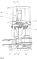
- the device 1 has a round bottom plate 2 supported by continuous rods 3,4 cover plate 5. A housing connected to it is not shown in the drawing.
- two support plates 6.7 are arranged between the bottom plate 2 and the top plate 5.
- drinking vessels are cleaned at three stations above the lower support plate 7 . Two other stations are used to pick up the drinking vessels or to hand them over.
- the supply of drinking vessels 8.9 is a horizontally rotating turntable 10 on which drinking vessels are placed by hand.
- a double guide 11 fixed to the device via a rod 12 on the carrier plate 7 is supported.
- a stop 13 is formed for the parked drinking vessels.
- a drinking vessel held against this stop 13 is then gripped by a lowered gripping device 14, here in the form of a vacuum suction cup.
- the gripping device 14 is pivoted about a central, vertical axis toward a second station 15, which in the exemplary embodiment is formed by a pre-rinsing unit. Consequently, another drinking vessel can then be placed on the turntable 10, which enables the device 1 to be continuously loaded with drinking vessels.
- a raised drinking vessel 8 is then lowered into the pre-rinse unit and previously cleaned.
- a gripping device following the gripping device 14 grips a drinking vessel, which can be obtained by pivoting the base 10 in the direction of the arrow, cf 6 , was spent in contact with the stop 13 of the guide 13.
- a drinking vessel 8 is lifted again and pivoted to a third station 16, in which a main cleaning takes place, for example in an ultrasonic bath.
- a subsequent cleaning and/or drying takes place in a fourth station 17 .
- the drinking vessels are placed on another rotating turntable 18 which rotates in the opposite direction to the turntable 10 , with the result that drinking vessels are pivoted against the stop 19 of the guide 20 .
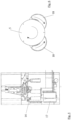
- 6 shows the two turntables 10,18 outside of the device 1, where the turntable 10 can be equipped with drinking vessels or the turntable 18 drinking vessels can be removed.
- a contributing factor is that a lifting drive 30 is arranged above the support plate 6 for adjusting the height of the central axis. Immediately below the support plate 6 and thus above the gripping devices 14, a pivoting drive 31 is provided for pivoting the central axis.
- the gripping devices 14 are connected to the central axis at a uniform radial distance in a common plane via a receiving star 32 . This means that the five gripping devices here are height-adjusted and pivoted synchronously.
- the number of stations corresponds to the number of gripping devices which are arranged over the circumference at a uniform pitch, in this case of 72°.
- a vacuum pump is also arranged on the carrier plate 6 in order to apply a negative pressure to the gripping devices 14 , which are designed here as vacuum suction cups.
- Guides 34,35 are also provided there for vertical guidance of the central axis.
Landscapes
- Specific Conveyance Elements (AREA)
Abstract
Description
- Die Erfindung betrifft eine mobile Vorrichtung für das Spülen von Trinkgefäßen, insbesondere von Gläsern und Bechern.
- In Haushalten genutzte Geschirrspülmaschinen sind hinlänglich bekannt. Für einen mobilen Einsatz sind diese jedoch wenig geeignet und ist insbesondere der Spülvorgang regelmäßig von erheblicher Dauer. Insoweit sind diese Geschirrspülmaschinen für beispielsweise eine mobile Verwendung in Festzelten auf Volksfesten ungeeignet.
- Tunnelgeschirrspülmaschinen Verwendung, bei denen zu reinigendes Geschirr gleichsam eine Waschstraße linear durchläuft. Dabei sind Längen von etlichen Metern durchaus üblich, hervorgerufen durch aufeinander abfolgende Stationen wie Vorreinigung, Hauptreinigung und Trocknung. Aufgrund dieser Länge sind derartige Tunnelgeschirrspülmaschinen regelmäßig nur zerlegt transportabel, was einen erheblichen Zeitaufwand für den Auf- bzw. Abbau bedeutet. Auch ein Verlasten beispielsweise in einem normalen Kombi ist aufgrund der Baulänge nur höchst selten möglich.
- Handspülvorrichtungen sind im Bereich des gewerblichen Gläserspülens keine wirkliche Alternative. Zum einen erfordern sie eine kostenpflichtige Spülkraft. Insbesondre kann jedoch aufgrund fehlerhafter Spültechnik die DIN 10511 "Gewerbliches Gläserspülen mit Glasspülmaschinen" nicht erfüllt werden. Grundsätzlich besteht darüber hinaus durch die regelmäßig angewendete Bürstentechnik die Gefahr einer Kreuzkontamination und des Glasbruchs wie auch einer schlechten Reinigung bspw. bei einer Verunreinigung eines Glases durch Lippenstift.
- Vor diesem Hintergrund macht die Erfindung es sich zur Aufgabe, eine äußerst kompakte und dennoch leistungsfähige mobile Vorrichtung für das Spülen von Trinkgefäßen zur Verfügung zu stellen, insbesondere für das Spülen von Gläsern und Bechern, die problemlos auch beispielsweise in einem Kombi transportabel ist und die der DIN 10511 genügt.
- Gelöst wird diese technische Problematik durch eine Vorrichtung gemäß des Anspruchs 1.
- Die Vorrichtung nach der Erfindung weist eine Vielzahl von Vorteilen auf. Zunächst ist die Vorrichtung äußerst kompakt und bedarf nur einer geringen Aufstellfläche. In einfacher Weise ist sie auch in einem Pkw verlastbar.
- Bei der Vorrichtung nach der Erfindung wird der lineare Weg beispielsweise in einer Tunnelgeschirrspülmaschine durch eine Kreisbewegung ersetzt und hierdurch eine sehr kurze Baulänge erreicht. Hierzu weist die Vorrichtung eine von einem Schwenkantrieb angetriebene, vertikale, zentrale Achse auf. In einer gemeinsamen Ebene sind radial gleichmäßig beabstandete, höhenstellbare Greifvorrichtungen vorgesehen, die an der Achse angebunden mitrotieren. Eine Steuerung koordiniert das Erfassen der Trinkgefäße, die Auf- bzw. Abbewegungen der Greifvorrichtungen bei einer Umdrehung an den einzelnen Stationen sowie die Abgabe der Trinkgefäße.
- Durch Absenken einer Greifvorrichtung an einer ersten Aufnahmestation wird ein Trinkgefäß von dieser ergriffen. Nach dem Ergreifen des Trinkgefäßes wird die Greifvorrichtung angehoben und mit oder nach dem Anheben wird mit Drehen der Achse dieses Trinkgefäß an eine nachfolgende Station umgesetzt und dort für eine Behandlung abgesenkt. Mit dem Absenken wird eine dieser ersten Greifvorrichtung nachfolgende zweite Greifvorrichtung gleichfalls abgesenkt und ergreift das nächste Trinkgefäß. Dieser Vorgang wiederholt sich mehrfach und nachdem etliche ringförmig angeordnete Stationen durchlaufen sind wird an einer letzten, einer Abgabestation, das Trinkgefäß durch Absenken der Greifvorrichtung abgesetzt.
- Die Vorrichtung nach der Erfindung erlaubt so einen weitgehenden kontinuierlichen Durchlauf und eine schonende, Glasbruch vermeidende Reinigung von Trinkgefäßen.
- Dabei kann vorgesehen sein, dass jede Greifvorrichtung über einen Hubantrieb verfügt. Bevorzugt wird jedoch, dass ein Hubantrieb für die Höhenstellung der zentralen Achse vorgesehen ist. Mit der Achse werden dann alle Greifvorrichtungen gleichzeitig angehoben bzw. abgesenkt.
- Vor diesem Hintergrund ist es zweckmäßig, wenn die Anzahl der Greifvorrichtungen der Anzahl der Stationen entspricht. Mit jedem Absenken der Greifvorrichtungen erfolgt somit eine Behandlung eines Trinkgefäßes an einer Station bzw. eine Aufnahme bzw. Abgabe eines solchen.
- Dabei hat es sich als zweckmäßig erwiesen, wenn die Greifvorrichtungen über den Umfang in einer gleichmäßigen Teilung angeordnet sind, wie auch die einzelnen Stationen. Von Station zu Station sind dann jeweils gleiche Drehwinkel vorgegeben.
- In konstruktiver Ausgestaltung kann dann vorgesehen sein, dass die Greifvorrichtungen an einem Aufnahmestern, einem Flügelrad oder einer einfachen Platte angeordnet sind.
- Die Ausbildung der Greifvorrichtungen ist weitgehend freibleibend. Bevorzugt werden Vakuumsauger. Eine Alternative stellen Fingern dar, die ein Trinkgefäß eingeklemmt halten.
- Auch die Ausbildung der Antriebe ist weitgehend freibleibend. Insbesondere ist an pneumatische und elektrische Antriebe gedacht, gegebenenfalls auch an mechanische.
- Dabei hat es sich als zweckmäßig erwiesen, wenn ein Hubantrieb und/oder ein Schwenkantrieb für die zentrale Achse und/oder eine Vakuumpumpe für die Beaufschlagung der Vakuumsauger mit einem Unterdruck oberhalb der Greifvorrichtungen angeordnet ist/sind.
- Darüber hinaus kann weiter vorgesehen sein, dass oberhalb der Greifvorrichtungen eine Führung für die zentrale Achse angeordnet ist.
- Diese Maßnahmen bieten den Vorteil, dass der Raum unterhalb der Greifvorrichtungen für die Anordnung der einzelnen Stationen und deren Ausgestaltung weitgehend freibleibend ist.
- Die Zu- und/oder die Abfuhr der Trinkgefäße kann auf Rutschen und/oder in Magazinen erfolgen. Eine Alternative bieten verschwenkbare, halbmondartige Böden, über denen jeweils eine feststehende Führung mit einem Anschlag angeordnet ist. Auf einen ersten Boden werden, im der Regel von Hand und außerhalb der Vorrichtung, eine bestimmte Anzahl von zu spülenden Trinkgefäßen abgestellt. Vorzugsweise entspricht die Anzahl der Trinkgefäße der Anzahl der Stationen. Mit jedem Verschwenken der Greifvorrichtungen verschwenkt der Boden in die Vorrichtung, bis ein weiteres Glas an den Anschlag stößt und dort von der nachfolgenden Greifvorrichtung erfasst werden kann.
- Die Abgabe der Trinkgefäße erfolgt dann auf einem gegenläufig verschwekbaren Boden.
- Steht ausreichent Platz neben den einzelnen Stationen zur Verfügung, kann in einer weiteren Alternative vorgesehen sein, dass die Zu- und/oder die Abfuhr der Trinkgefäße auf Drehtellern erfolgt, über denen jeweils eine feststehende Führung mit einem Anschlag angeordnet ist. Eine solche Zu- bzw. Abfuhr der Trinkgefäße hat den Vorteil, dass ein kontinuierlicher Betrieb der Vorrichtung möglich ist.
- Für den Reinigungsprozess eines Trinkgefäßes ist eine zweite Station nach der Aufnahmestation für eine Vorreinigung vorgesehen, eine dritte Station für eine Hauptreinigung, insbesondere in einem Ultraschall-Bad, und eine vierte Station für eine Nachreinigung und/oder Trocknung, bevor das Trinkgefäß an der letzten, der Abgabestation, abgegeben wird.
- Das Ultraschall-Bad bietet den Vorteil einer sehr guten Reinigung auch bei einer Verschmutzung durch bspw. Lippenstift, aber auch bei Herpes, Viren wie Corona-Viren oder dergleichen mehr.
- Weitere Stationen sind darüber hinaus möglich, bspw. kann die Vorrichtung noch durch eine Kontrollstufe erweitert werden, in der ein gespültes Trinkgefäß auf Sauberkeit und Keimfreiheit kontrolliert wird.
- Letztlich ist vorgesehen, dass die Vorrichtung eine Einhausung aufweist, mit zwei Öffnungen für die Zuführung und die Abgabe der Trinkgefäße.
- Die Erfindung wird anhand der Zeichnung näher erläutert, in der lediglich ein Ausführungsbeispiele dargestellt ist. In der Zeichnung zeigt:
- Fig. 1:
- eine erste isometrische Darstellung der Vorrichtung nach der Erfindung ohne Einhausung,
- Fig. 2:
- eine zweite isometrische Darstellung,
- Fig. 3:
- eine erste seitliche Darstellung,
- Fig. 4:
- eine zweite seitliche Darstellung,
- Fig. 5:
- eine dritte seitliche Darstellung und
- Fig. 6:
- eine Draufsicht.
- Die Vorrichtung 1 weist über einer runden Bodenplatte 2 eine von durchgehenden Stäben 3,4 getragene Deckplatte 5 auf. Eine daran angeschlossene Einhausung ist in der Zeichnung nicht dargestellt.
- Zwischen der Bodenplatte 2 und der Deckplatte 5 sind zwei Trägerplatten 6,7 angeordnet. Bei dem Ausführungsbeispiel der Vorrichtung 1 erfolgt oberhalb der unteren Trägerplatte 7 die Reinigung von Trinkgefäßen an drei Stationen. Zwei weitere Stationen dienen der Aufnahme der Trinkgefäße bzw. deren Abgabe.
- Der Zuführung von Trinkgefäßen 8,9 dient ein in der Horizontalen rotierender Drehteller 10, auf dem von Hand Trinkgefäße abgestellt werden.
- Oberhalb des Drehtellers 10 ist eine doppelte Führung 11 vorrichtungsfest über einen Stäbe 12 auf der Trägerplatte 7 abgestützt. Durch die Führungen 11 wird weiter ein Anschlag 13 für die abgestellten Trinkgefäße ausgebildet. Ein gegen diesen Anschlag 13 gehaltenes Trinkgefäß wird sodann von einer abgesenkten Greifvorrichtung 14, hier in Form eines Vakuumsaugers, erfasst. Nach dem Anheben der Greifvorrichtung 14 in die in
Figur 1 wiedergegebene Position wird die Greifvorrichtung 14 um eine zentrale, vertikale Achse hin zu einer zweiten Station 15 verschwenkt, die bei dem Ausführungsbeispiel durch eine Vorspüleinheit ausgebildet wird. Mithin kann dann ein weiters Trinkgefäß auf dem Drehteller 10 abgesetzt werden, womit ein kontinuierliches Beschicken der Vorrichtung 1 mit Trinkgefäßen ermöglicht ist. - Ein angehobenes Trinkgefäß 8 wird sodann in die Vorspüleinheit abgesenkt und vorab gereinigt. Synchron mit diesem Absenken erfasst eine der Greifvorrichtung 14 folgende Greifvorrichtung ein Trinkgefäß, das durch Verschwenken des Bodens 10 gemäß Pfeilrichtung, vgl. auch
Fig. 6 , in Anlage an den Anschlag 13 der Führung 13 verbracht wurde. - Nach der Vorreinigung in der Vorspüleinheit der Station 15 wird ein Trinkgefäß 8 erneut angehoben und zu einer dritten Station 16 verschwenkt, in der eine Hauptreinigung beispielsweise in einem Ultraschallbad erfolgt. Nach erneutem Anheben und Verschwenken und folgendem Absenken erfolgt in einer vierten Station 17 eine Nachreinigung und/oder Trocknung.
- Nach der Vollendung des Reinigungsprozesses werden die Trinkgefäße auf einem weiteren rotierenden Drehteller 18 abgesetzt, der gegenläufig zu dem Drehteller 10 rotiert, womit Trinkgefäße gegen den Anschlag 19 der Führung 20 verschwenkt werden.
Fig. 6 zeigt die beiden Drehteller 10,18 außerhalb der Vorrichtung 1, wo der Drehteller 10 mit Trinkgefäßen bestückt werden kann bzw. dem Drehteller 18 Trinkgefäße entnommen werden können. - Um ausreichend Platz für die Drehteller 10,18 zu erhalten, können einzelne Stationen über der Trägerplatte 7 aufgeständert sein.
- Unterhalb der Trägerplatte 7 sind Drehantriebe 25,26 für die Drehteller 10,18 vorgesehen. Auch Spülpumpen 27,28 für die Vorspülung bzw. die Nachspülung sind dort angeordnet. Damit verbleibt der Raum zwischen den Trägerplatten 7,8 für die Gestaltung der einzelnen Stationen weitestgehend frei.
- Dazu trägt bei, dass oberhalb der Trägerplatte 6 ein Hubantrieb 30 für eine Höhenstellung der zentralen Achse angeordnet ist. Unmittelbar unterhalb der Trägerplatte 6 und damit über den Greifvorrichtungen 14 ist ein Schwenkantrieb 31 für das Verschwenken der zentralen Achse vorgesehen.
- Über einen Aufnahmestern 32 sind die Greifvorrichtungen 14 radial gleichmäßig beabstandet in einer gemeinsamen Ebene an die zentrale Achse angebunden. Damit werden die hier fünf Greifvorrichtungen synchron höhengestellt und verschwenkt.
- Bei dem Ausführungsbeispiel entspricht die Anzahl der Stationen der Anzahl der Greifvorrichtungen, die über den Umfang in einer gleichmäßigen Teilung hier von 72° angeordnet sind. Um die hier als Vakuumsauger ausgebildeten Greifvorrichtungen 14 mit einem Unterdruck zu beaufschlagen, ist auf der Trägerplatte 6 eine Vakuumpumpe noch angeordnet. Auch sind dort Führungen 34,35 für eine vertikale Führung der zentralen Achse vorgesehen.
-
- 1.
- Vorrichtung
- 2.
- Bodenplatte
- 3.
- Stab
- 4.
- Stab
- 5.
- Deckplatte
- 6.
- Trägerplatte
- 7.
- Trägerplatte
- 8.
- Trinkgefäß
- 9.
- Trinkgefäß
- 10.
- Drehteller
- 11.
- Führung
- 12.
- Stab
- 13.
- Anschlag
- 14.
- Greifvorrichtung
- 15.
- Station
- 16.
- Station
- 17.
- Station
- 18.
- Drehteller
- 19.
- Führung
- 20.
- Anschlag
- 21. 22. 23. 24. 25.
- Drehantrieb
- 26.
- Drehantrieb
- 27.
- Spülpumpe
- 28.
- Spülpumpe
- 29. 30.
- Hubantrieb
- 31.
- Schwenkantrieb
- 32.
- Aufnahmestern
- 33.
- Vakuumpumpe
- 34.
- Führung
- 35.
- Führung
Claims (12)
- Mobile Vorrichtung für das Spülen von Trinkgefäßen, insbesondere von Gläsern und Bechern, gekennzeichnet durch eine von einem Schwenkantrieb (31) angetriebene, vertikale, zentrale Achse, an der radial gleichmäßig beabstandet Greifvorrichtungen (14) in einer gemeinsamen Ebene mitrotierend und höhenstellbar angebunden sind, und durch eine Steuerung für ein Erfassen, Umsetzen und Abgabe der Trinkgefäße (8,9) durch Anheben und Absenken der Greifvorrichtungen (14) während einer Umdrehung der Achse von einer ersten Aufnahmestation der Trinkgefäße über weitere, ringförmig angeordneten Stationen (15 bis 17) bis hin zu einer Abgabestation der Trinkgefäße.
- Vorrichtung nach Anspruch 1, dadurch gekennzeichnet, dass ein Hubantrieb (30) für die Höhenstellung der zentralen Achse vorgesehen ist.
- Vorrichtung nach einem oder mehreren der vorangehenden Ansprüche, dadurch gekennzeichnet, dass die Anzahl der Greifvorrichtungen (14) der Anzahl der Stationen entspricht.
- Vorrichtung nach einem oder mehreren der vorangehenden Ansprüche, dadurch gekennzeichnet, dass die Greifvorrichtungen (14) über den Umfang in einer gleichmäßigen Teilung angeordnet sind.
- Vorrichtung nach einem oder mehreren der vorangehenden Ansprüche, dadurch gekennzeichnet, dass die Greifvorrichtungen (14) an einem Aufnahmestern (32), einem Flügelrad oder einer Platte angeordnet sind.
- Vorrichtung nach einem oder mehreren der vorangehenden Ansprüche, dadurch gekennzeichnet, dass die Greifvorrichtungen (14) durch Vakuumsauger ausgebildet werden oder mit Fingern versehen sind, die ein Trinkgefäß eingeklemmt halten.
- Vorrichtung nach einem oder mehreren der vorangehenden Ansprüche, dadurch gekennzeichnet, dass ein Hubantrieb (30) und/oder ein Schwenkantrieb (31) für die zentrale Achse und/oder eine Vakuumpumpe (33) oberhalb der Greifvorrichtungen (14) angeordnet ist/sind.
- Vorrichtung nach einem oder mehreren der vorangehenden Ansprüche, dadurch gekennzeichnet, dass oberhalb der Greifvorrichtungen (14) eine vertikale Führung (34,35) für die zentrale Achse angeordnet ist.
- Vorrichtung nach einem oder mehreren der vorangehenden Ansprüche, dadurch gekennzeichnet, dass die Zu- und/oder die Abfuhr der Trinkgefäße auf Rutschen und/oder in Magazinen erfolgt.
- Vorrichtung nach einem oder mehreren der vorangehenden Ansprüche 1 bis 8, dadurch gekennzeichnet, dass die Zu- und/oder die Abfuhr der Trinkgefäße auf verschwenkbaren, halbmondartigen Böden (10,18) erfolgt, über denen jeweils eine feststehende Führung (11,19) mit einem Anschlag (13,20) angeordnet ist.
- Vorrichtung nach einem oder mehreren der vorangehenden Ansprüche 1 bis 8, dadurch gekennzeichnet, dass die Zu- und/oder die Abfuhr der Trinkgefäße auf Drehtellern erfolgt, über denen jeweils eine feststehende Führung mit einem Anschlag angeordnet ist.
- Vorrichtung nach einem oder mehreren der vorangehenden Ansprüche, gekennzeichnet durch eine zweite Station (15) für eine Vorreinigung, durch eine dritte Station (16) für eine Hauptreinigung und eine vierte Station (17) für eine Nachreinigung und/oder Trocknung.
Applications Claiming Priority (1)
| Application Number | Priority Date | Filing Date | Title |
|---|---|---|---|
| DE102021003939 | 2021-07-30 |
Publications (2)
| Publication Number | Publication Date |
|---|---|
| EP4124277A1 true EP4124277A1 (de) | 2023-02-01 |
| EP4124277B1 EP4124277B1 (de) | 2024-08-21 |
Family
ID=83004466
Family Applications (1)
| Application Number | Title | Priority Date | Filing Date |
|---|---|---|---|
| EP22000188.7A Active EP4124277B1 (de) | 2021-07-30 | 2022-07-28 | Vorrichtung für das spülen von trinkgefässen |
Country Status (1)
| Country | Link |
|---|---|
| EP (1) | EP4124277B1 (de) |
Cited By (2)
| Publication number | Priority date | Publication date | Assignee | Title |
|---|---|---|---|---|
| WO2025007203A1 (pt) * | 2023-07-05 | 2025-01-09 | De Oliveira Carlos Eduardo | Dispositivo automatico para higienização e armazenamento de copos |
| NL2037839B1 (en) | 2024-05-31 | 2025-12-18 | Pronto Solutions B V | Device and method for washing and drying cups |
Citations (7)
| Publication number | Priority date | Publication date | Assignee | Title |
|---|---|---|---|---|
| EP0733337A2 (de) * | 1995-03-23 | 1996-09-25 | WOHLEB SYSTEME GmbH | Reinigungsvorrichtung für Mehrwege-Geschirr |
| US5598859A (en) * | 1994-12-16 | 1997-02-04 | Krones Ag Hermann Kronseder Maschinenfabrik | Cleaning machine for receptacles |
| KR20030017203A (ko) * | 2001-08-24 | 2003-03-03 | 최기창 | 음용컵 자동 세척장치 |
| WO2005072596A1 (en) * | 2004-01-30 | 2005-08-11 | Hot Kleen Co., Ltd. | Automatic washer for cups |
| US20110135833A1 (en) * | 2008-08-06 | 2011-06-09 | Basf Se | Positioning device and method with rotary indexing table for monolith-based automobile and chemical catalysts |
| US20170166431A1 (en) * | 2014-07-18 | 2017-06-15 | Khs Gmbh | Container treatment machine |
| DE202017006320U1 (de) * | 2017-12-10 | 2018-12-12 | Leo FRANK | Durchlauf-Spülmaschine, insbesondere für Kunststoff-Mehrwegbecher |
Family Cites Families (3)
| Publication number | Priority date | Publication date | Assignee | Title |
|---|---|---|---|---|
| KR101891543B1 (ko) * | 2016-12-14 | 2018-08-28 | (주)넥셈 | 컵 자동 세척장치 |
| KR102052837B1 (ko) * | 2018-09-18 | 2019-12-05 | 한국수자원공사 | 초음파와 플라즈마를 융합한 컵 세척 및 살균 장치와, 컵 세척 및 살균방법 |
| KR102048655B1 (ko) * | 2019-04-24 | 2019-11-25 | 김홍성 | Dsa전극을 이용한 개인용 컵 자동 살균세척장치 |
-
2022
- 2022-07-28 EP EP22000188.7A patent/EP4124277B1/de active Active
Patent Citations (7)
| Publication number | Priority date | Publication date | Assignee | Title |
|---|---|---|---|---|
| US5598859A (en) * | 1994-12-16 | 1997-02-04 | Krones Ag Hermann Kronseder Maschinenfabrik | Cleaning machine for receptacles |
| EP0733337A2 (de) * | 1995-03-23 | 1996-09-25 | WOHLEB SYSTEME GmbH | Reinigungsvorrichtung für Mehrwege-Geschirr |
| KR20030017203A (ko) * | 2001-08-24 | 2003-03-03 | 최기창 | 음용컵 자동 세척장치 |
| WO2005072596A1 (en) * | 2004-01-30 | 2005-08-11 | Hot Kleen Co., Ltd. | Automatic washer for cups |
| US20110135833A1 (en) * | 2008-08-06 | 2011-06-09 | Basf Se | Positioning device and method with rotary indexing table for monolith-based automobile and chemical catalysts |
| US20170166431A1 (en) * | 2014-07-18 | 2017-06-15 | Khs Gmbh | Container treatment machine |
| DE202017006320U1 (de) * | 2017-12-10 | 2018-12-12 | Leo FRANK | Durchlauf-Spülmaschine, insbesondere für Kunststoff-Mehrwegbecher |
Cited By (2)
| Publication number | Priority date | Publication date | Assignee | Title |
|---|---|---|---|---|
| WO2025007203A1 (pt) * | 2023-07-05 | 2025-01-09 | De Oliveira Carlos Eduardo | Dispositivo automatico para higienização e armazenamento de copos |
| NL2037839B1 (en) | 2024-05-31 | 2025-12-18 | Pronto Solutions B V | Device and method for washing and drying cups |
Also Published As
| Publication number | Publication date |
|---|---|
| EP4124277B1 (de) | 2024-08-21 |
Similar Documents
| Publication | Publication Date | Title |
|---|---|---|
| DE69505060T2 (de) | Reinigungsvorrichtung mit Bürsten und diese verwendendes Reinigungssystem für scheibenförmige Gegenstände | |
| EP4124277B1 (de) | Vorrichtung für das spülen von trinkgefässen | |
| DE19781822B4 (de) | Reinigungsstation zur Verwendung bei einem System zum Reinigen, Spülen und Trocknen von Halbleiterscheiben | |
| DE8806156U1 (de) | Maschine zum Glasieren von Ton- und Porzellanwaren und Werkstückhalter hierfür | |
| DE3715305A1 (de) | Waschanlage zur aeusseren reinigung von gefaessen | |
| DE202009012064U1 (de) | Vorrichtung zum Fördern von Objekten, Etikettiervorrichtung, Inspektionsvorrichtung und Rotationsfüller mit einer derartigen Fördervorrichtung | |
| EP3326939B1 (de) | Vorrichtung zum drehen von auf einem förderer aufstehenden behältern | |
| DE19925653A1 (de) | System und Verfahren zum Steuern der Ausrichtung eines Substrats | |
| EP3169457A1 (de) | Behälterbehandlungsmaschine | |
| DE2905376A1 (de) | Transportstern fuer flaschen o.dgl. | |
| DE10113898A1 (de) | Einrichtung zum Zuführen und/oder Wegführen von mit Objekten gefüllten Magazinen | |
| EP1214733B1 (de) | Vorrichtung zum be- und entladen von substraten | |
| EP0906619A1 (de) | Vorrichtung für den transport von substraten | |
| WO2000015420A1 (de) | Vorrichtung für den transport von kreisscheibenförmigen substraten von einer zuführstation über mehrere zwischenstationen zu einer endstation | |
| DE102011083139A1 (de) | Substratbehandlungsverfahren und Substratbehandlungsanlage | |
| EP1952900A1 (de) | Vorrichtung zum Reinigen von Behältnissen | |
| EP2150164B1 (de) | Abräumvorrichtung, insbesondere für serviertabletts | |
| DE19716523A1 (de) | Dreh- und Zustelleinheit mit integriertem Vakuumsystem und Anlage mit einer solchen Einheit | |
| EP0844054A1 (de) | Rundtisch-Glasiermaschine | |
| DE1683924C3 (de) | Vorrichtung zum Zentrieren von zu behandelnden Tellern u.dgl. Formungen | |
| DE2935004A1 (de) | Putzmaschine fuer keramische formlinge | |
| DE1432398C3 (de) | Rotierende Reinigungsmaschine für Behälter, z.B. Flaschen | |
| DE171765C (de) | ||
| CH704761A2 (de) | Vorrichtung zur Be- und/oder Entladung einer Schleifmaschine für Streckwerkswalzen. | |
| DE2256944A1 (de) | Umsetzvorrichtung fuer keramische formlinge |
Legal Events
| Date | Code | Title | Description |
|---|---|---|---|
| PUAI | Public reference made under article 153(3) epc to a published international application that has entered the european phase |
Free format text: ORIGINAL CODE: 0009012 |
|
| STAA | Information on the status of an ep patent application or granted ep patent |
Free format text: STATUS: THE APPLICATION HAS BEEN PUBLISHED |
|
| AK | Designated contracting states |
Kind code of ref document: A1 Designated state(s): AL AT BE BG CH CY CZ DE DK EE ES FI FR GB GR HR HU IE IS IT LI LT LU LV MC MK MT NL NO PL PT RO RS SE SI SK SM TR |
|
| STAA | Information on the status of an ep patent application or granted ep patent |
Free format text: STATUS: REQUEST FOR EXAMINATION WAS MADE |
|
| 17P | Request for examination filed |
Effective date: 20230405 |
|
| RBV | Designated contracting states (corrected) |
Designated state(s): AL AT BE BG CH CY CZ DE DK EE ES FI FR GB GR HR HU IE IS IT LI LT LU LV MC MK MT NL NO PL PT RO RS SE SI SK SM TR |
|
| STAA | Information on the status of an ep patent application or granted ep patent |
Free format text: STATUS: EXAMINATION IS IN PROGRESS |
|
| 17Q | First examination report despatched |
Effective date: 20231212 |
|
| GRAP | Despatch of communication of intention to grant a patent |
Free format text: ORIGINAL CODE: EPIDOSNIGR1 |
|
| STAA | Information on the status of an ep patent application or granted ep patent |
Free format text: STATUS: GRANT OF PATENT IS INTENDED |
|
| RIC1 | Information provided on ipc code assigned before grant |
Ipc: A47L 15/13 20060101ALN20240502BHEP Ipc: A47L 15/00 20060101AFI20240502BHEP |
|
| RIC1 | Information provided on ipc code assigned before grant |
Ipc: A47L 15/13 20060101ALN20240506BHEP Ipc: A47L 15/00 20060101AFI20240506BHEP |
|
| INTG | Intention to grant announced |
Effective date: 20240527 |
|
| GRAS | Grant fee paid |
Free format text: ORIGINAL CODE: EPIDOSNIGR3 |
|
| GRAA | (expected) grant |
Free format text: ORIGINAL CODE: 0009210 |
|
| STAA | Information on the status of an ep patent application or granted ep patent |
Free format text: STATUS: THE PATENT HAS BEEN GRANTED |
|
| AK | Designated contracting states |
Kind code of ref document: B1 Designated state(s): AL AT BE BG CH CY CZ DE DK EE ES FI FR GB GR HR HU IE IS IT LI LT LU LV MC MK MT NL NO PL PT RO RS SE SI SK SM TR |
|
| REG | Reference to a national code |
Ref country code: GB Ref legal event code: FG4D Free format text: NOT ENGLISH |
|
| REG | Reference to a national code |
Ref country code: CH Ref legal event code: EP |
|
| REG | Reference to a national code |
Ref country code: IE Ref legal event code: FG4D Free format text: LANGUAGE OF EP DOCUMENT: GERMAN |
|
| REG | Reference to a national code |
Ref country code: DE Ref legal event code: R096 Ref document number: 502022001478 Country of ref document: DE |
|
| REG | Reference to a national code |
Ref country code: NL Ref legal event code: FP |
|
| REG | Reference to a national code |
Ref country code: LT Ref legal event code: MG9D |
|
| PG25 | Lapsed in a contracting state [announced via postgrant information from national office to epo] |
Ref country code: NO Free format text: LAPSE BECAUSE OF FAILURE TO SUBMIT A TRANSLATION OF THE DESCRIPTION OR TO PAY THE FEE WITHIN THE PRESCRIBED TIME-LIMIT Effective date: 20241121 |
|
| PG25 | Lapsed in a contracting state [announced via postgrant information from national office to epo] |
Ref country code: FI Free format text: LAPSE BECAUSE OF FAILURE TO SUBMIT A TRANSLATION OF THE DESCRIPTION OR TO PAY THE FEE WITHIN THE PRESCRIBED TIME-LIMIT Effective date: 20240821 Ref country code: GR Free format text: LAPSE BECAUSE OF FAILURE TO SUBMIT A TRANSLATION OF THE DESCRIPTION OR TO PAY THE FEE WITHIN THE PRESCRIBED TIME-LIMIT Effective date: 20241122 Ref country code: PL Free format text: LAPSE BECAUSE OF FAILURE TO SUBMIT A TRANSLATION OF THE DESCRIPTION OR TO PAY THE FEE WITHIN THE PRESCRIBED TIME-LIMIT Effective date: 20240821 Ref country code: PT Free format text: LAPSE BECAUSE OF FAILURE TO SUBMIT A TRANSLATION OF THE DESCRIPTION OR TO PAY THE FEE WITHIN THE PRESCRIBED TIME-LIMIT Effective date: 20241223 |
|
| PG25 | Lapsed in a contracting state [announced via postgrant information from national office to epo] |
Ref country code: BG Free format text: LAPSE BECAUSE OF FAILURE TO SUBMIT A TRANSLATION OF THE DESCRIPTION OR TO PAY THE FEE WITHIN THE PRESCRIBED TIME-LIMIT Effective date: 20240821 |
|
| PG25 | Lapsed in a contracting state [announced via postgrant information from national office to epo] |
Ref country code: LV Free format text: LAPSE BECAUSE OF FAILURE TO SUBMIT A TRANSLATION OF THE DESCRIPTION OR TO PAY THE FEE WITHIN THE PRESCRIBED TIME-LIMIT Effective date: 20240821 |
|
| PG25 | Lapsed in a contracting state [announced via postgrant information from national office to epo] |
Ref country code: IS Free format text: LAPSE BECAUSE OF FAILURE TO SUBMIT A TRANSLATION OF THE DESCRIPTION OR TO PAY THE FEE WITHIN THE PRESCRIBED TIME-LIMIT Effective date: 20241221 |
|
| PG25 | Lapsed in a contracting state [announced via postgrant information from national office to epo] |
Ref country code: HR Free format text: LAPSE BECAUSE OF FAILURE TO SUBMIT A TRANSLATION OF THE DESCRIPTION OR TO PAY THE FEE WITHIN THE PRESCRIBED TIME-LIMIT Effective date: 20240821 |
|
| PG25 | Lapsed in a contracting state [announced via postgrant information from national office to epo] |
Ref country code: RS Free format text: LAPSE BECAUSE OF FAILURE TO SUBMIT A TRANSLATION OF THE DESCRIPTION OR TO PAY THE FEE WITHIN THE PRESCRIBED TIME-LIMIT Effective date: 20241121 Ref country code: ES Free format text: LAPSE BECAUSE OF FAILURE TO SUBMIT A TRANSLATION OF THE DESCRIPTION OR TO PAY THE FEE WITHIN THE PRESCRIBED TIME-LIMIT Effective date: 20240821 |
|
| PG25 | Lapsed in a contracting state [announced via postgrant information from national office to epo] |
Ref country code: RS Free format text: LAPSE BECAUSE OF FAILURE TO SUBMIT A TRANSLATION OF THE DESCRIPTION OR TO PAY THE FEE WITHIN THE PRESCRIBED TIME-LIMIT Effective date: 20241121 Ref country code: PT Free format text: LAPSE BECAUSE OF FAILURE TO SUBMIT A TRANSLATION OF THE DESCRIPTION OR TO PAY THE FEE WITHIN THE PRESCRIBED TIME-LIMIT Effective date: 20241223 Ref country code: PL Free format text: LAPSE BECAUSE OF FAILURE TO SUBMIT A TRANSLATION OF THE DESCRIPTION OR TO PAY THE FEE WITHIN THE PRESCRIBED TIME-LIMIT Effective date: 20240821 Ref country code: NO Free format text: LAPSE BECAUSE OF FAILURE TO SUBMIT A TRANSLATION OF THE DESCRIPTION OR TO PAY THE FEE WITHIN THE PRESCRIBED TIME-LIMIT Effective date: 20241121 Ref country code: LV Free format text: LAPSE BECAUSE OF FAILURE TO SUBMIT A TRANSLATION OF THE DESCRIPTION OR TO PAY THE FEE WITHIN THE PRESCRIBED TIME-LIMIT Effective date: 20240821 Ref country code: IS Free format text: LAPSE BECAUSE OF FAILURE TO SUBMIT A TRANSLATION OF THE DESCRIPTION OR TO PAY THE FEE WITHIN THE PRESCRIBED TIME-LIMIT Effective date: 20241221 Ref country code: HR Free format text: LAPSE BECAUSE OF FAILURE TO SUBMIT A TRANSLATION OF THE DESCRIPTION OR TO PAY THE FEE WITHIN THE PRESCRIBED TIME-LIMIT Effective date: 20240821 Ref country code: GR Free format text: LAPSE BECAUSE OF FAILURE TO SUBMIT A TRANSLATION OF THE DESCRIPTION OR TO PAY THE FEE WITHIN THE PRESCRIBED TIME-LIMIT Effective date: 20241122 Ref country code: FI Free format text: LAPSE BECAUSE OF FAILURE TO SUBMIT A TRANSLATION OF THE DESCRIPTION OR TO PAY THE FEE WITHIN THE PRESCRIBED TIME-LIMIT Effective date: 20240821 Ref country code: ES Free format text: LAPSE BECAUSE OF FAILURE TO SUBMIT A TRANSLATION OF THE DESCRIPTION OR TO PAY THE FEE WITHIN THE PRESCRIBED TIME-LIMIT Effective date: 20240821 Ref country code: BG Free format text: LAPSE BECAUSE OF FAILURE TO SUBMIT A TRANSLATION OF THE DESCRIPTION OR TO PAY THE FEE WITHIN THE PRESCRIBED TIME-LIMIT Effective date: 20240821 |
|
| PG25 | Lapsed in a contracting state [announced via postgrant information from national office to epo] |
Ref country code: SM Free format text: LAPSE BECAUSE OF FAILURE TO SUBMIT A TRANSLATION OF THE DESCRIPTION OR TO PAY THE FEE WITHIN THE PRESCRIBED TIME-LIMIT Effective date: 20240821 Ref country code: DK Free format text: LAPSE BECAUSE OF FAILURE TO SUBMIT A TRANSLATION OF THE DESCRIPTION OR TO PAY THE FEE WITHIN THE PRESCRIBED TIME-LIMIT Effective date: 20240821 Ref country code: RO Free format text: LAPSE BECAUSE OF FAILURE TO SUBMIT A TRANSLATION OF THE DESCRIPTION OR TO PAY THE FEE WITHIN THE PRESCRIBED TIME-LIMIT Effective date: 20240821 |
|
| PG25 | Lapsed in a contracting state [announced via postgrant information from national office to epo] |
Ref country code: EE Free format text: LAPSE BECAUSE OF FAILURE TO SUBMIT A TRANSLATION OF THE DESCRIPTION OR TO PAY THE FEE WITHIN THE PRESCRIBED TIME-LIMIT Effective date: 20240821 |
|
| PG25 | Lapsed in a contracting state [announced via postgrant information from national office to epo] |
Ref country code: CZ Free format text: LAPSE BECAUSE OF FAILURE TO SUBMIT A TRANSLATION OF THE DESCRIPTION OR TO PAY THE FEE WITHIN THE PRESCRIBED TIME-LIMIT Effective date: 20240821 |
|
| PG25 | Lapsed in a contracting state [announced via postgrant information from national office to epo] |
Ref country code: SK Free format text: LAPSE BECAUSE OF FAILURE TO SUBMIT A TRANSLATION OF THE DESCRIPTION OR TO PAY THE FEE WITHIN THE PRESCRIBED TIME-LIMIT Effective date: 20240821 Ref country code: IT Free format text: LAPSE BECAUSE OF FAILURE TO SUBMIT A TRANSLATION OF THE DESCRIPTION OR TO PAY THE FEE WITHIN THE PRESCRIBED TIME-LIMIT Effective date: 20240821 |
|
| REG | Reference to a national code |
Ref country code: DE Ref legal event code: R097 Ref document number: 502022001478 Country of ref document: DE |
|
| PLBE | No opposition filed within time limit |
Free format text: ORIGINAL CODE: 0009261 |
|
| STAA | Information on the status of an ep patent application or granted ep patent |
Free format text: STATUS: NO OPPOSITION FILED WITHIN TIME LIMIT |
|
| PGFP | Annual fee paid to national office [announced via postgrant information from national office to epo] |
Ref country code: LU Payment date: 20250613 Year of fee payment: 4 Ref country code: BE Payment date: 20250625 Year of fee payment: 4 |
|
| 26N | No opposition filed |
Effective date: 20250522 |
|
| PGFP | Annual fee paid to national office [announced via postgrant information from national office to epo] |
Ref country code: NL Payment date: 20250721 Year of fee payment: 4 |
|
| PG25 | Lapsed in a contracting state [announced via postgrant information from national office to epo] |
Ref country code: SE Free format text: LAPSE BECAUSE OF FAILURE TO SUBMIT A TRANSLATION OF THE DESCRIPTION OR TO PAY THE FEE WITHIN THE PRESCRIBED TIME-LIMIT Effective date: 20240821 |
|
| PGFP | Annual fee paid to national office [announced via postgrant information from national office to epo] |
Ref country code: DE Payment date: 20250613 Year of fee payment: 4 |
|
| PGFP | Annual fee paid to national office [announced via postgrant information from national office to epo] |
Ref country code: FR Payment date: 20250725 Year of fee payment: 4 Ref country code: AT Payment date: 20251020 Year of fee payment: 4 |
|
| REG | Reference to a national code |
Ref country code: CH Ref legal event code: H13 Free format text: ST27 STATUS EVENT CODE: U-0-0-H10-H13 (AS PROVIDED BY THE NATIONAL OFFICE) Effective date: 20260224 |
|
| PG25 | Lapsed in a contracting state [announced via postgrant information from national office to epo] |
Ref country code: CH Free format text: LAPSE BECAUSE OF NON-PAYMENT OF DUE FEES Effective date: 20250731 |