EP4124203B1 - System und verfahren zum ausbringen und einholen eines autonomen unterwasserfahrzeugs durch ein von einem schiff geschlepptes einholfahrzeug, unterwasser-erkundungsanordnung - Google Patents
System und verfahren zum ausbringen und einholen eines autonomen unterwasserfahrzeugs durch ein von einem schiff geschlepptes einholfahrzeug, unterwasser-erkundungsanordnung Download PDFInfo
- Publication number
- EP4124203B1 EP4124203B1 EP20785544.6A EP20785544A EP4124203B1 EP 4124203 B1 EP4124203 B1 EP 4124203B1 EP 20785544 A EP20785544 A EP 20785544A EP 4124203 B1 EP4124203 B1 EP 4124203B1
- Authority
- EP
- European Patent Office
- Prior art keywords
- ship
- launch ramp
- recovery vehicle
- recovery
- vehicle
- Prior art date
- Legal status (The legal status is an assumption and is not a legal conclusion. Google has not performed a legal analysis and makes no representation as to the accuracy of the status listed.)
- Active
Links
Images


Classifications
-
- B—PERFORMING OPERATIONS; TRANSPORTING
- B63—SHIPS OR OTHER WATERBORNE VESSELS; RELATED EQUIPMENT
- B63B—SHIPS OR OTHER WATERBORNE VESSELS; EQUIPMENT FOR SHIPPING
- B63B21/00—Tying-up; Shifting, towing, or pushing equipment; Anchoring
- B63B21/56—Towing or pushing equipment
- B63B21/66—Equipment specially adapted for towing underwater objects or vessels, e.g. fairings for tow-cables
-
- B—PERFORMING OPERATIONS; TRANSPORTING
- B63—SHIPS OR OTHER WATERBORNE VESSELS; RELATED EQUIPMENT
- B63B—SHIPS OR OTHER WATERBORNE VESSELS; EQUIPMENT FOR SHIPPING
- B63B27/00—Arrangement of ship-based loading or unloading equipment for cargo or passengers
- B63B27/14—Arrangement of ship-based loading or unloading equipment for cargo or passengers of ramps, gangways or outboard ladders ; Pilot lifts
- B63B27/143—Ramps
-
- B—PERFORMING OPERATIONS; TRANSPORTING
- B63—SHIPS OR OTHER WATERBORNE VESSELS; RELATED EQUIPMENT
- B63B—SHIPS OR OTHER WATERBORNE VESSELS; EQUIPMENT FOR SHIPPING
- B63B27/00—Arrangement of ship-based loading or unloading equipment for cargo or passengers
- B63B27/36—Arrangement of ship-based loading or unloading equipment for floating cargo
-
- B—PERFORMING OPERATIONS; TRANSPORTING
- B63—SHIPS OR OTHER WATERBORNE VESSELS; RELATED EQUIPMENT
- B63G—OFFENSIVE OR DEFENSIVE ARRANGEMENTS ON VESSELS; MINE-LAYING; MINE-SWEEPING; SUBMARINES; AIRCRAFT CARRIERS
- B63G8/00—Underwater vessels, e.g. submarines; Equipment specially adapted therefor
- B63G8/001—Underwater vessels adapted for special purposes, e.g. unmanned underwater vessels; Equipment specially adapted therefor, e.g. docking stations
-
- B—PERFORMING OPERATIONS; TRANSPORTING
- B63—SHIPS OR OTHER WATERBORNE VESSELS; RELATED EQUIPMENT
- B63G—OFFENSIVE OR DEFENSIVE ARRANGEMENTS ON VESSELS; MINE-LAYING; MINE-SWEEPING; SUBMARINES; AIRCRAFT CARRIERS
- B63G8/00—Underwater vessels, e.g. submarines; Equipment specially adapted therefor
- B63G8/42—Towed underwater vessels
-
- B—PERFORMING OPERATIONS; TRANSPORTING
- B66—HOISTING; LIFTING; HAULING
- B66D—CAPSTANS; WINCHES; TACKLES, e.g. PULLEY BLOCKS; HOISTS
- B66D1/00—Rope, cable, or chain winding mechanisms; Capstans
- B66D1/28—Other constructional details
- B66D1/40—Control devices
- B66D1/48—Control devices automatic
- B66D1/52—Control devices automatic for varying rope or cable tension, e.g. when recovering craft from water
-
- B—PERFORMING OPERATIONS; TRANSPORTING
- B63—SHIPS OR OTHER WATERBORNE VESSELS; RELATED EQUIPMENT
- B63B—SHIPS OR OTHER WATERBORNE VESSELS; EQUIPMENT FOR SHIPPING
- B63B27/00—Arrangement of ship-based loading or unloading equipment for cargo or passengers
- B63B27/16—Arrangement of ship-based loading or unloading equipment for cargo or passengers of lifts or hoists
- B63B2027/165—Deployment or recovery of underwater vehicles using lifts or hoists
-
- B—PERFORMING OPERATIONS; TRANSPORTING
- B63—SHIPS OR OTHER WATERBORNE VESSELS; RELATED EQUIPMENT
- B63G—OFFENSIVE OR DEFENSIVE ARRANGEMENTS ON VESSELS; MINE-LAYING; MINE-SWEEPING; SUBMARINES; AIRCRAFT CARRIERS
- B63G8/00—Underwater vessels, e.g. submarines; Equipment specially adapted therefor
- B63G8/001—Underwater vessels adapted for special purposes, e.g. unmanned underwater vessels; Equipment specially adapted therefor, e.g. docking stations
- B63G2008/002—Underwater vessels adapted for special purposes, e.g. unmanned underwater vessels; Equipment specially adapted therefor, e.g. docking stations unmanned
- B63G2008/004—Underwater vessels adapted for special purposes, e.g. unmanned underwater vessels; Equipment specially adapted therefor, e.g. docking stations unmanned autonomously operating
Definitions
- the present invention relates generally to the field of underwater exploration and more particularly to a system and method for deploying and recovering an autonomous underwater vehicle by a recovery vehicle towed by a surface vessel. It has applications in particular in the field of shipbuilding.
- the duration of exploration operations can also be increased without being limited by physiological or legal constraints.
- a scanning task by movement in a given geographical area can be assigned to an autonomous underwater exploration vehicle comprising sonars and recorders without an operator having to continuously monitor the movements of the underwater vehicle.
- WO 2014/135522 A1 US 8,430 049 B1 , FR 2 968 268 A1 , EP 2 468 620 A1 And US 2012/160143 A1 .
- Some of these systems use launch ramps but there is no provision for any means of absorbing the impact of waves, particularly in WO 2014/135522 A1 if damping is provided it is only between the underwater vehicle and guidance means.
- the present invention proposes a solution which makes it possible to teleoperate and even automate all the operations of an underwater vehicle from its deployment to its recovery, from a surface vessel, the latter preferably being a surface drone navigating without personnel on board.
- a system for deploying and recovering an autonomous underwater vehicle by a recovery vehicle towed by a surface ship comprising the ship and the recovery vehicle, the towing being ensured by a towing cable connecting the recovery vehicle to the ship, the system being configured so that when not in use the underwater vehicle is stored in a housing of the recovery vehicle and the recovery vehicle is stored out of water in the ship, the recovery vehicle comprising two opposite ends along its length, including an end for receiving the autonomous underwater vehicle giving access to the housing, the system being configured to allow the deployment to be carried out in two stages, a first stage of submersion of the recovery vehicle with the underwater vehicle stored in said recovery vehicle, a second stage of release of the underwater vehicle by removing the latter from the housing of the submerged recovery vehicle once the towed recovery vehicle has been moved a determined distance from the ship, the system being configured to allow the recovery to be carried out in two stages, a first stage of submersion of the recovery vehicle with the underwater vehicle stored in said recovery vehicle, a second stage of release
- the vessel comprises a launch ramp which is tiltable and the system is configured to store the recovery vehicle on the launch ramp, the launch ramp having a longitudinal extension and comprising two longitudinal ends, a forward end on the bow side of the ship and a rear end on the stern side of the ship, said tilting launch ramp being able to take at least two positions: a raised position in which the stored recovery vehicle is out of the water, said raised launch ramp being above the waterline of the ship, and an inclined position in which the rear end of the launch ramp is submerged, the system comprising a translational device allowing, in the inclined position of the launch ramp, the recovery vehicle to move along the launch ramp to be submerged and to be able to move away from the ship while being towed by the latter during deployment and to be raised along the launch ramp during recovery and the rear end of the launch ramp comprises buoyancy means allowing said launch ramp in the inclined position to flap according to the height of the water at the level of the buoyancy means.
- the invention also relates to an underwater exploration assembly comprising the system of the invention as well as an autonomous underwater vehicle.
- the invention finally relates to a method for implementing the assembly according to the invention in which, with a ship storing on a tilting launch ramp an autonomous underwater vehicle stored in a housing of a recovery vehicle, during deployment of the autonomous underwater vehicle, the launch ramp is tilted in order to bring it into an inclined position in which the rear end of the launch ramp is submerged, the recovery vehicle is submerged which is towed by the ship using a tow cable, the tow cable is unwound so that the recovery vehicle storing the autonomous underwater vehicle moves away from the ship, then at a determined distance from the ship, the autonomous underwater vehicle is released from the recovery vehicle.
- the present invention relates to the field of navigation and underwater exploration. It therefore proposes a solution for the automatic deployment and recovery of an autonomous underwater vehicle 12 (AUV).
- the platform on which the autonomous underwater vehicle 12 is recovered may be of various types, in particular an autonomous, remotely operated or conventional ship 1.
- the platform is configured to limit on board movements due to the state of the sea, in particular due to swell, and even more so accelerations linked to the state of the sea.
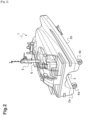
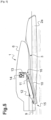
- a recovery vehicle 11 which internally comprises a housing allowing storage of the autonomous underwater vehicle 12.
- At least one of the faces of the housing of the recovery vehicle is provided with longitudinal openings or slots allowing the various fins and lateral appendages of the autonomous underwater vehicle to be inserted therein and to circulate/slide therein.
- These longitudinal openings may or may not open and, possibly, only partially on the external lateral sides of the recovery vehicle.
- These longitudinal openings may have a flared shape towards the rear, on the receiving end side, in order to facilitate the entry of the autonomous underwater vehicle into the housing of the recovery vehicle.
- These longitudinal openings may also be used as a means of indexing the axial rotational position of the autonomous underwater vehicle with respect to the recovery vehicle.
- the docking is carried out while submerged at a sufficient depth so that wave movements are greatly reduced.
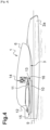
- the recovery vehicle 11 which is towed from the front (unlike ROVs which are lowered and raised vertically) can be motorized, and in any case, it is capable of holding a position under the water surface in all degrees of freedom, for example thanks to active fins.
- the towing of the recovery vehicle 11 is carried out by a towing cable 13 which may further comprise a data link between the platform and the recovery vehicle 11 and/or a power link, in particular electrical, between the two.
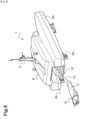
- the recovery vehicle 11 comprises a controlled removable automatic mooring system for locking the autonomous underwater vehicle 12 in the recovery vehicle 11.
- the autonomous underwater vehicle 12 and the recovery vehicle 11 comprise a system for automatic recovery of the vehicle 12 in the vehicle 11 (“homing system”) with in particular sensors and other equipment allowing automatic guidance of the autonomous underwater vehicle 12 so that it comes to be stored inside the housing of the recovery vehicle 11.
- homing system a system for automatic recovery of the vehicle 12 in the vehicle 11
- sensors and other equipment allowing automatic guidance of the autonomous underwater vehicle 12 so that it comes to be stored inside the housing of the recovery vehicle 11.
- the autonomous underwater vehicle 12 and the recovery vehicle 11 comprise a data transfer connection system between them, and possibly with the platform, and/or an electrical connection allowing the electrical recharging of the autonomous underwater vehicle 12 which comprises rechargeable batteries.
- a launch ramp 10 For launching/immersing from the platform and bringing back on board/onto the platform of the autonomous underwater vehicle 12 stored in the recovery vehicle 11, a launch ramp 10 that can be made semi-submerged is implemented.
- This launch ramp 10 is articulated by a pivot connection, or even a ball joint, with the platform and a system for lifting and locking in the high/raised position of the launch ramp 10 is implemented.
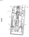
- the exemplified vessel 1 shown in the figures is of the catamaran type and it has a hull formed of two parallel lateral hulls 2a, 2b separated from each other by an intermediate connecting zone 3 located above the waterline 9.
- the two lateral parts of the hull forming the hulls 2a, 2b have a wave-piercing type shape at the front.
- the intermediate connecting zone 3 is out of the water, above the waterline 9 and can be seen better on the figure 3 .
- the upper part of the ship includes, in addition to a deck 6, equipment 5 useful for navigation such as for example a radar, one or more radio antennas, transponder, etc. Regulatory equipment is also provided such as regulatory lights/lighting.
- the hull of the ship has externally, above the waterline, strips 8a, 8b made of elastomeric material intended to absorb lateral impacts against the hull.
- the hull (or sides) of the ship 1 makes it possible to delimit an interior volume in which a recovery vehicle 11 can be stored, itself storing, in its own sides, an autonomous underwater vehicle 12 when they are not deployed/operational, i.e. not put into the sea.
- the ship 1 is mechanically propelled, in this example by propellers at the rear 4a, 4b, which can be steered, arranged at the bottom of the hulls.
- the ship 1 has other propellers at the front 7a, 7b, which cannot be steered, arranged through the hulls.
- the propellers 4a, 4b, 7a, 7b are preferably powered by electric motors and the electrical energy can be provided by rechargeable batteries and/or photovoltaic cells and/or a generator with a thermal engine and/or a fuel cell.
- Vessel 1 has a typical length of 25 m and a typical width of 6 m. However, it can have a length of between 6 m and 150 m and a width of between 0.8 m and 30 m depending on the model.
- the intermediate connecting zone 3 comprises towards the rear of the ship 1 a launch ramp 10 for the recovery vehicle 11, said launch ramp 10 also serving during the recovery of the recovery vehicle 11.
- the recovery vehicle 11 is connected by a towing cable 13 to the ship 1.
- the towing cable 13 can be unwound for launching or rewound for recovery of the recovery vehicle 11 by means of a motorized and controlled winding-unwinding device 14.
- the towing cable 13 is fixed towards the front of the recovery vehicle 11
- the launch ramp 10 is in the raised position and it is in the general continuity of the intermediate connection zone 3 and it seals the hull of the ship 1 in this zone.
- Launch Pad 10 is articulated and can tilt to an angle as seen in the Figures 5 to 8 .
- the hinge of the launch ramp 10 is located towards the front end 16 of the launch ramp 10 and, thus, the rear end 15 of the launch ramp 10 can be lowered and brought under water to be submerged, below the waterline 9 ( figure 5 ) when the launch ramp is tilted.
- the tilting/tilting can be provided by a pivot joint, the axis of the joint being transversely elongated (perpendicular to the sagittal plane of the ship), along the width of the launch ramp which therefore has a possible angular displacement in a single plane, the sagittal plane.
- a tilting having more degrees of freedom is provided with possible angular displacements in two perpendicular planes, sagittal and, in addition, transverse. In the latter case, this can make it possible to compensate for pitching movements and in addition rolling/listing, in particular when the launch ramp 10 is equipped with a buoyancy reserve in order to be semi-submerged when it is in the low position, with or without a load (including the recovery vehicle 11) in place.
- This compensation makes it possible to prevent the surface of the inclined launch ramp from moving too far from the horizontal in the transverse direction, the ramp being inclined in the longitudinal direction.
- the compensation is passive but an active compensation is provided as an alternative or in addition by effectors controlled according to measurements of pitch sensors, or even in addition to roll.
- a passive or active damping system for rotational movements around the pivot or ball joint or other type of suitable articulation can be implemented.
- the launching ramp thanks to its buoyancy means, can flap freely in an inclined position, depending on the waves, a flapping damping device being implemented. Under these conditions, the launching ramp therefore passively adapts to the height of the sea surface relative to the ship. Stops may be provided to limit the flapping stroke in the inclined position of the launching ramp.
- a material is provided on the underside of the launch ramp 1 which absorbs the impact of waves on the inclined launch ramp.
- the material is a porous double skin absorbing the impact of the waves.
- the recovery vehicle 11 may be passive in terms of its movements underwater, the latter being due only to towing, or active controlled propulsion means may be provided for the recovery vehicle 11.
- the recovery vehicle 11 comprises controlled guidance means, typically fins, rudders, etc. or steerable thrusters.
- the towing cable 13 may be a simple rope or, preferably, include electrical and/or data connections for control and command of the recovery vehicle 11 and, possibly, electrical power supply and data exchange with the recovery vehicle 11 and the autonomous underwater vehicle 12 when the latter is stored in the vehicle 11.
- the active recovery vehicle 11 with active controlled propulsion means, controlled guidance means can operate in active mode or in passive mode depending on the case. It is also expected that the recovery vehicle 11 will be mixed, having fins for certain degrees of freedom and a thruster for others.
- the autonomous underwater vehicle 12 includes in particular propulsion, guidance and measurement equipment. Propulsion is carried out from the rear, using a propeller in this example. It can be noted that said propeller protrudes from the rear of the recovery vehicle 11 when the autonomous underwater vehicle 12 is stored in the recovery vehicle 11 while the front and the majority of the autonomous underwater vehicle 12 is well protected, in a housing inside the recovery vehicle 11.
- the autonomous underwater vehicle 12 and the recovery vehicle 11 comprise an automatic docking system so that the autonomous underwater vehicle 12, on the one hand, automatically positions itself in the axis of the recovery vehicle 11, at the rear of the latter, opposite the receiving end 17 of said recovery vehicle 11, and, on the other hand, enters it to be housed in the housing of said recovery vehicle 11 and moors there.
- the recovery vehicle 11 is streamlined, hydrodynamically adapted, to provide low resistance to submerged/in-water progress and high towing speeds of up to 8 knots.
- the autonomous underwater vehicle 12 is also streamlined, with a suitable hydrodynamic shape, in the form of a torpedo, in order to offer low resistance to submerged/in-water advancement and high autonomous displacement speeds of up to 10 knots.
- the automatic recovery of the autonomous underwater vehicle 12 in the recovery vehicle 11 can be carried out while the latter is towed, and this up to a speed of 5 knots.
- FIGs 4 to 7 represent the deployment operations of the figure 4 to 7 or, by equivalence and conversely, of recovery of the figure 7 to 4 .
- the autonomous underwater vehicle 12 is stored in the recovery vehicle 11, the latter being stored on the raised launch ramp 10, closing the intermediate connection zone 3 of the ship 1.
- the autonomous underwater vehicle 12 and the recovery vehicle 11 are stored in the sides of the ship 1, they can be moved quickly and in a manner protected from the environment, between exploration zones or to an anchorage in port.
- the launch ramp 10 is tilted so that its rear end 15 is submerged and the rear of the autonomous underwater vehicle 12 stored in the recovery vehicle 11 is also, preferably, submerged/in the water.
- the recovery vehicle 11 and the autonomous underwater vehicle 12 it stores are inclined towards the rear and downwards and tend to descend along the launch ramp 10, the towing cable 13 making it possible to control the descent for launching/immersion (or conversely to allow the ascent during recovery).
- the raising of the rear end 15 of the launch ramp 10 is motorized.
- the tilting of the launch ramp 10 for lowering its rear end 15 is preferably motorized.
- a system of cables or chains connected to the rear end 15 of the launch ramp 10 or to this rear end allows to control the descent and the ascent.
- An electric motor of winch or jack type can be used.
- the rear end 15 of the launch ramp 10 preferably has some buoyancy, which allows it to follow the water level.
- the launch ramp 10 may comprise rollers and/or rollers and/or bearings and/or slides and/or sliding strips facilitating the descent and ascent of the recovery vehicle 11.
- a guidance system may be provided between the recovery vehicle 11 and the launch ramp 10, for example a longitudinal slot in the surface of the launch ramp 10 in which a fin of the recovery vehicle 11 can circulate.
- a towing cable guide 13 may also be provided ensuring that the cable 13 remains substantially along the launch ramp 10 during deployment or recovery of the recovery vehicle 11.
- the launch ramp 10 may be provided on its upper face with a cable guide on a slide so that the cable guide is close to the upper surface of the launch ramp 10 at the rear end of the launch ramp 10 when the recovery vehicle 11 is at sea and is being brought back into the ship 1.
- FIG 6 the recovery vehicle 11 has moved away from the advancing vessel 1, the towing cable 13 having been unwound and the recovery vehicle 11 being towed by the vessel 1.
- the autonomous underwater vehicle 12 is still stored in the recovery vehicle 11.
- the release of the autonomous underwater vehicle 12 is carried out at a depth of at least forty meters or, at the very least, at a depth where the surface movements of the water, in particular the swell, no longer have any effect.
- a depth is preferably also chosen for the automatic recovery of the autonomous underwater vehicle 12 in the housing of the recovery vehicle 11.
- the recovery vehicle 11 may have multiple rearwardly open housings for storing multiple autonomous underwater vehicles 12 or a single large housing for storing multiple autonomous underwater vehicles 12 in series.
- the vessel may have multiple tilting launch ramps for as many recovery vehicles 11.
Landscapes
- Engineering & Computer Science (AREA)
- Mechanical Engineering (AREA)
- Chemical & Material Sciences (AREA)
- Combustion & Propulsion (AREA)
- Ocean & Marine Engineering (AREA)
- Aviation & Aerospace Engineering (AREA)
- Control Of Position, Course, Altitude, Or Attitude Of Moving Bodies (AREA)
Claims (9)
Applications Claiming Priority (2)
| Application Number | Priority Date | Filing Date | Title |
|---|---|---|---|
| FR1911281A FR3101846B1 (fr) | 2019-10-10 | 2019-10-10 | Système et procédé de déploiement et de récupération d’engin autonome sous-marin par un véhicule de récupération remorqué par un navire, ensemble d’exploration sous-marine |
| PCT/EP2020/078336 WO2021069624A1 (fr) | 2019-10-10 | 2020-10-08 | Système et procédé de déploiement et de récupération d'engin autonome sous-marin par un véhicule de récupération remorqué par un navire, ensemble d'exploration sous-marine |
Publications (2)
| Publication Number | Publication Date |
|---|---|
| EP4124203A2 EP4124203A2 (de) | 2023-02-01 |
| EP4124203B1 true EP4124203B1 (de) | 2024-09-18 |
Family
ID=69375499
Family Applications (1)
| Application Number | Title | Priority Date | Filing Date |
|---|---|---|---|
| EP20785544.6A Active EP4124203B1 (de) | 2019-10-10 | 2020-10-08 | System und verfahren zum ausbringen und einholen eines autonomen unterwasserfahrzeugs durch ein von einem schiff geschlepptes einholfahrzeug, unterwasser-erkundungsanordnung |
Country Status (4)
| Country | Link |
|---|---|
| US (1) | US12459605B2 (de) |
| EP (1) | EP4124203B1 (de) |
| FR (1) | FR3101846B1 (de) |
| WO (1) | WO2021069624A1 (de) |
Families Citing this family (8)
| Publication number | Priority date | Publication date | Assignee | Title |
|---|---|---|---|---|
| NO345094B1 (en) | 2018-09-21 | 2020-09-28 | Usea As | A marine structure comprising a launch and recovery system |
| CN113772022B (zh) * | 2021-08-13 | 2022-07-01 | 鹏城实验室 | 水下机器人回收装置与母船 |
| DE102021127215A1 (de) | 2021-10-20 | 2023-04-20 | Silent Yachts Trading GmbH | Stauraumsystem mit Stauraum und Hebebühne für ein Mehrrumpfschiff |
| CN114195031B (zh) * | 2021-10-27 | 2024-04-02 | 武汉船用机械有限责任公司 | 航行器的拖拽装置和拖拽方法 |
| CN114872841A (zh) * | 2022-04-12 | 2022-08-09 | 株洲中车时代电气股份有限公司 | 自主水下探测系统、方法及自动回收和布放auv的方法 |
| CN116588256A (zh) * | 2023-05-23 | 2023-08-15 | 中船绿洲镇江船舶辅机有限公司 | 一种舱外捕捉舱内转运的收放系统及使用方法 |
| CN116902144B (zh) * | 2023-09-11 | 2023-12-22 | 国家深海基地管理中心 | 一种auv释放回收用的装置及方法 |
| GB2641353A (en) * | 2024-04-17 | 2025-12-03 | Kraken Tech Group Limited | Maritime craft |
Family Cites Families (8)
| Publication number | Priority date | Publication date | Assignee | Title |
|---|---|---|---|---|
| US6779475B1 (en) * | 2003-09-15 | 2004-08-24 | The United States Of America As Represented By The Secretary Of The Navy | Launch and recovery system for unmanned underwater vehicles |
| US7581507B2 (en) * | 2007-02-26 | 2009-09-01 | Physical Sciences, Inc. | Launch and recovery devices for water vehicles and methods of use |
| US8430049B1 (en) * | 2009-07-13 | 2013-04-30 | Vehicle Control Technologies, Inc. | Launch and recovery systems and methods |
| US20120160143A1 (en) * | 2010-02-23 | 2012-06-28 | Bailey Stephen L | Vessel with active mechanism for controlled towing |
| US8967067B2 (en) * | 2010-12-07 | 2015-03-03 | Thales | System for launching and recovering underwater vehicles, notably towed underwater vehicles |
| FR2968268B1 (fr) * | 2010-12-07 | 2013-08-30 | Thales Sa | Systeme de mise a l'eau et de recuperation d'engins sous-marins, notamment d'engins sous-marins tractes |
| FR2969574B1 (fr) * | 2010-12-23 | 2013-11-01 | Eca | Dispositif de mise a l'eau et de recuperation d'un engin marin, et procede de mise a l'eau et de recuperation associe. |
| FR3002916B1 (fr) * | 2013-03-05 | 2015-03-06 | Thales Sa | Systeme et procede de recuperation d'un engin sous-marin autonome |
-
2019
- 2019-10-10 FR FR1911281A patent/FR3101846B1/fr active Active
-
2020
- 2020-10-08 EP EP20785544.6A patent/EP4124203B1/de active Active
- 2020-10-08 WO PCT/EP2020/078336 patent/WO2021069624A1/fr not_active Ceased
- 2020-10-08 US US17/767,821 patent/US12459605B2/en active Active
Also Published As
| Publication number | Publication date |
|---|---|
| FR3101846A1 (fr) | 2021-04-16 |
| US20240083553A1 (en) | 2024-03-14 |
| WO2021069624A1 (fr) | 2021-04-15 |
| EP4124203A2 (de) | 2023-02-01 |
| US12459605B2 (en) | 2025-11-04 |
| FR3101846B1 (fr) | 2023-01-27 |
Similar Documents
| Publication | Publication Date | Title |
|---|---|---|
| EP4124203B1 (de) | System und verfahren zum ausbringen und einholen eines autonomen unterwasserfahrzeugs durch ein von einem schiff geschlepptes einholfahrzeug, unterwasser-erkundungsanordnung | |
| EP3784558B1 (de) | System zur einsetzen und zurückholen einer autonomen unterwasservorrichtung, verfahren zur verwendung | |
| EP3984875B1 (de) | Stapellauf- und einbergungsplattform für boot, und entsprechendes stapellauf- und einbergungsverfahren | |
| EP2648970B1 (de) | System zum freigeben und bergen eines unterwassergeräts | |
| EP3707067B1 (de) | Schwimmende struktur zum aussetzen und einholen von mindestens einem autonomen wasserfahrzeug durch ein schiff, entsprechendes verfahren, entsprechendes system und entsprechendes schiff | |
| CA2875597C (fr) | Systeme de mise a l'eau et de recuperation d'engins sous-marins, notamment d'engins sous-marins tractes | |
| EP3717346B1 (de) | Schwimmendes wasserfahrzeug mit abnehmbarem messkiel | |
| EP3523192B1 (de) | Messsystem für wasserumgebungen mit einem oberflächenschiff und einer tauchvorrichtung | |
| EP4110689B1 (de) | Schiff, das ein system zum anpassen eines abnehmbaren moduls umfasst, und angepasstes abnehmbares modul | |
| WO2022167490A1 (fr) | Navire autonome motorisé monocoque à quille lestée transformable en trimaran | |
| WO2014203244A1 (en) | Multitasking watercraft | |
| EP4121345B1 (de) | System zur handhabung von meeres- oder unterwasserdrohnen durch einen schwimmenden ponton mit einem abnehmbaren drohnenschnittstellenmodul, angepasstes schiff | |
| WO2025238609A1 (fr) | Système de transport à hydroptère | |
| EP0298856A1 (de) | Mehrzweck-Angriffswasserfahrzeug | |
| EP0347288A1 (de) | Unterwasserfahrzeug mit eigenem Antrieb für Auffindung versunkener Gegenstände | |
| FR3162201A1 (fr) | Systeme de transport a hydroptere | |
| CH721820A2 (fr) | Système de transport à hydroptère | |
| FR2668446A1 (fr) | Perfectionnements apportes aux engins sous-marins filo-guides. | |
| EP0440517A1 (de) | Navigationssystem mit einem schwimmenden Körper zur Erforschung des Unterwassermilieus | |
| WO2024236531A1 (fr) | Système de transport à hydroptère à stabilité améliorée | |
| FR3148779A1 (fr) | Systeme de transport a hydroptere a stabilite amelioree |
Legal Events
| Date | Code | Title | Description |
|---|---|---|---|
| STAA | Information on the status of an ep patent application or granted ep patent |
Free format text: STATUS: UNKNOWN |
|
| STAA | Information on the status of an ep patent application or granted ep patent |
Free format text: STATUS: THE INTERNATIONAL PUBLICATION HAS BEEN MADE |
|
| PUAI | Public reference made under article 153(3) epc to a published international application that has entered the european phase |
Free format text: ORIGINAL CODE: 0009012 |
|
| STAA | Information on the status of an ep patent application or granted ep patent |
Free format text: STATUS: REQUEST FOR EXAMINATION WAS MADE |
|
| 17P | Request for examination filed |
Effective date: 20220325 |
|
| AK | Designated contracting states |
Kind code of ref document: A2 Designated state(s): AL AT BE BG CH CY CZ DE DK EE ES FI FR GB GR HR HU IE IS IT LI LT LU LV MC MK MT NL NO PL PT RO RS SE SI SK SM TR |
|
| RAP3 | Party data changed (applicant data changed or rights of an application transferred) |
Owner name: EXAIL |
|
| GRAP | Despatch of communication of intention to grant a patent |
Free format text: ORIGINAL CODE: EPIDOSNIGR1 |
|
| STAA | Information on the status of an ep patent application or granted ep patent |
Free format text: STATUS: GRANT OF PATENT IS INTENDED |
|
| INTG | Intention to grant announced |
Effective date: 20240417 |
|
| GRAS | Grant fee paid |
Free format text: ORIGINAL CODE: EPIDOSNIGR3 |
|
| GRAA | (expected) grant |
Free format text: ORIGINAL CODE: 0009210 |
|
| STAA | Information on the status of an ep patent application or granted ep patent |
Free format text: STATUS: THE PATENT HAS BEEN GRANTED |
|
| AK | Designated contracting states |
Kind code of ref document: B1 Designated state(s): AL AT BE BG CH CY CZ DE DK EE ES FI FR GB GR HR HU IE IS IT LI LT LU LV MC MK MT NL NO PL PT RO RS SE SI SK SM TR |
|
| REG | Reference to a national code |
Ref country code: GB Ref legal event code: FG4D Free format text: NOT ENGLISH |
|
| REG | Reference to a national code |
Ref country code: CH Ref legal event code: EP |
|
| P01 | Opt-out of the competence of the unified patent court (upc) registered |
Free format text: CASE NUMBER: APP_48471/2024 Effective date: 20240823 |
|
| REG | Reference to a national code |
Ref country code: IE Ref legal event code: FG4D Free format text: LANGUAGE OF EP DOCUMENT: FRENCH |
|
| REG | Reference to a national code |
Ref country code: DE Ref legal event code: R096 Ref document number: 602020037996 Country of ref document: DE |
|
| REG | Reference to a national code |
Ref country code: LT Ref legal event code: MG9D |
|
| PG25 | Lapsed in a contracting state [announced via postgrant information from national office to epo] |
Ref country code: GR Free format text: LAPSE BECAUSE OF FAILURE TO SUBMIT A TRANSLATION OF THE DESCRIPTION OR TO PAY THE FEE WITHIN THE PRESCRIBED TIME-LIMIT Effective date: 20241219 Ref country code: FI Free format text: LAPSE BECAUSE OF FAILURE TO SUBMIT A TRANSLATION OF THE DESCRIPTION OR TO PAY THE FEE WITHIN THE PRESCRIBED TIME-LIMIT Effective date: 20240918 |
|
| PG25 | Lapsed in a contracting state [announced via postgrant information from national office to epo] |
Ref country code: BG Free format text: LAPSE BECAUSE OF FAILURE TO SUBMIT A TRANSLATION OF THE DESCRIPTION OR TO PAY THE FEE WITHIN THE PRESCRIBED TIME-LIMIT Effective date: 20240918 |
|
| PG25 | Lapsed in a contracting state [announced via postgrant information from national office to epo] |
Ref country code: LV Free format text: LAPSE BECAUSE OF FAILURE TO SUBMIT A TRANSLATION OF THE DESCRIPTION OR TO PAY THE FEE WITHIN THE PRESCRIBED TIME-LIMIT Effective date: 20240918 |
|
| PG25 | Lapsed in a contracting state [announced via postgrant information from national office to epo] |
Ref country code: HR Free format text: LAPSE BECAUSE OF FAILURE TO SUBMIT A TRANSLATION OF THE DESCRIPTION OR TO PAY THE FEE WITHIN THE PRESCRIBED TIME-LIMIT Effective date: 20240918 |
|
| REG | Reference to a national code |
Ref country code: NL Ref legal event code: MP Effective date: 20240918 |
|
| PG25 | Lapsed in a contracting state [announced via postgrant information from national office to epo] |
Ref country code: RS Free format text: LAPSE BECAUSE OF FAILURE TO SUBMIT A TRANSLATION OF THE DESCRIPTION OR TO PAY THE FEE WITHIN THE PRESCRIBED TIME-LIMIT Effective date: 20241218 |
|
| PG25 | Lapsed in a contracting state [announced via postgrant information from national office to epo] |
Ref country code: RS Free format text: LAPSE BECAUSE OF FAILURE TO SUBMIT A TRANSLATION OF THE DESCRIPTION OR TO PAY THE FEE WITHIN THE PRESCRIBED TIME-LIMIT Effective date: 20241218 Ref country code: LV Free format text: LAPSE BECAUSE OF FAILURE TO SUBMIT A TRANSLATION OF THE DESCRIPTION OR TO PAY THE FEE WITHIN THE PRESCRIBED TIME-LIMIT Effective date: 20240918 Ref country code: HR Free format text: LAPSE BECAUSE OF FAILURE TO SUBMIT A TRANSLATION OF THE DESCRIPTION OR TO PAY THE FEE WITHIN THE PRESCRIBED TIME-LIMIT Effective date: 20240918 Ref country code: GR Free format text: LAPSE BECAUSE OF FAILURE TO SUBMIT A TRANSLATION OF THE DESCRIPTION OR TO PAY THE FEE WITHIN THE PRESCRIBED TIME-LIMIT Effective date: 20241219 Ref country code: FI Free format text: LAPSE BECAUSE OF FAILURE TO SUBMIT A TRANSLATION OF THE DESCRIPTION OR TO PAY THE FEE WITHIN THE PRESCRIBED TIME-LIMIT Effective date: 20240918 Ref country code: BG Free format text: LAPSE BECAUSE OF FAILURE TO SUBMIT A TRANSLATION OF THE DESCRIPTION OR TO PAY THE FEE WITHIN THE PRESCRIBED TIME-LIMIT Effective date: 20240918 |
|
| REG | Reference to a national code |
Ref country code: AT Ref legal event code: MK05 Ref document number: 1724487 Country of ref document: AT Kind code of ref document: T Effective date: 20240918 |
|
| PG25 | Lapsed in a contracting state [announced via postgrant information from national office to epo] |
Ref country code: NL Free format text: LAPSE BECAUSE OF FAILURE TO SUBMIT A TRANSLATION OF THE DESCRIPTION OR TO PAY THE FEE WITHIN THE PRESCRIBED TIME-LIMIT Effective date: 20240918 |
|
| PG25 | Lapsed in a contracting state [announced via postgrant information from national office to epo] |
Ref country code: IS Free format text: LAPSE BECAUSE OF FAILURE TO SUBMIT A TRANSLATION OF THE DESCRIPTION OR TO PAY THE FEE WITHIN THE PRESCRIBED TIME-LIMIT Effective date: 20250118 Ref country code: PT Free format text: LAPSE BECAUSE OF FAILURE TO SUBMIT A TRANSLATION OF THE DESCRIPTION OR TO PAY THE FEE WITHIN THE PRESCRIBED TIME-LIMIT Effective date: 20250120 |
|
| PG25 | Lapsed in a contracting state [announced via postgrant information from national office to epo] |
Ref country code: RO Free format text: LAPSE BECAUSE OF FAILURE TO SUBMIT A TRANSLATION OF THE DESCRIPTION OR TO PAY THE FEE WITHIN THE PRESCRIBED TIME-LIMIT Effective date: 20240918 Ref country code: SM Free format text: LAPSE BECAUSE OF FAILURE TO SUBMIT A TRANSLATION OF THE DESCRIPTION OR TO PAY THE FEE WITHIN THE PRESCRIBED TIME-LIMIT Effective date: 20240918 |
|
| PG25 | Lapsed in a contracting state [announced via postgrant information from national office to epo] |
Ref country code: ES Free format text: LAPSE BECAUSE OF FAILURE TO SUBMIT A TRANSLATION OF THE DESCRIPTION OR TO PAY THE FEE WITHIN THE PRESCRIBED TIME-LIMIT Effective date: 20240918 |
|
| PG25 | Lapsed in a contracting state [announced via postgrant information from national office to epo] |
Ref country code: EE Free format text: LAPSE BECAUSE OF FAILURE TO SUBMIT A TRANSLATION OF THE DESCRIPTION OR TO PAY THE FEE WITHIN THE PRESCRIBED TIME-LIMIT Effective date: 20240918 Ref country code: AT Free format text: LAPSE BECAUSE OF FAILURE TO SUBMIT A TRANSLATION OF THE DESCRIPTION OR TO PAY THE FEE WITHIN THE PRESCRIBED TIME-LIMIT Effective date: 20240918 |
|
| PG25 | Lapsed in a contracting state [announced via postgrant information from national office to epo] |
Ref country code: CZ Free format text: LAPSE BECAUSE OF FAILURE TO SUBMIT A TRANSLATION OF THE DESCRIPTION OR TO PAY THE FEE WITHIN THE PRESCRIBED TIME-LIMIT Effective date: 20240918 Ref country code: PL Free format text: LAPSE BECAUSE OF FAILURE TO SUBMIT A TRANSLATION OF THE DESCRIPTION OR TO PAY THE FEE WITHIN THE PRESCRIBED TIME-LIMIT Effective date: 20240918 |
|
| PG25 | Lapsed in a contracting state [announced via postgrant information from national office to epo] |
Ref country code: SK Free format text: LAPSE BECAUSE OF FAILURE TO SUBMIT A TRANSLATION OF THE DESCRIPTION OR TO PAY THE FEE WITHIN THE PRESCRIBED TIME-LIMIT Effective date: 20240918 Ref country code: IT Free format text: LAPSE BECAUSE OF FAILURE TO SUBMIT A TRANSLATION OF THE DESCRIPTION OR TO PAY THE FEE WITHIN THE PRESCRIBED TIME-LIMIT Effective date: 20240918 |
|
| REG | Reference to a national code |
Ref country code: CH Ref legal event code: PL |
|
| REG | Reference to a national code |
Ref country code: DE Ref legal event code: R097 Ref document number: 602020037996 Country of ref document: DE |
|
| PG25 | Lapsed in a contracting state [announced via postgrant information from national office to epo] |
Ref country code: MC Free format text: LAPSE BECAUSE OF FAILURE TO SUBMIT A TRANSLATION OF THE DESCRIPTION OR TO PAY THE FEE WITHIN THE PRESCRIBED TIME-LIMIT Effective date: 20240918 |
|
| PG25 | Lapsed in a contracting state [announced via postgrant information from national office to epo] |
Ref country code: DK Free format text: LAPSE BECAUSE OF FAILURE TO SUBMIT A TRANSLATION OF THE DESCRIPTION OR TO PAY THE FEE WITHIN THE PRESCRIBED TIME-LIMIT Effective date: 20240918 |
|
| PG25 | Lapsed in a contracting state [announced via postgrant information from national office to epo] |
Ref country code: LU Free format text: LAPSE BECAUSE OF NON-PAYMENT OF DUE FEES Effective date: 20241008 Ref country code: BE Free format text: LAPSE BECAUSE OF NON-PAYMENT OF DUE FEES Effective date: 20241031 |
|
| PG25 | Lapsed in a contracting state [announced via postgrant information from national office to epo] |
Ref country code: CH Free format text: LAPSE BECAUSE OF NON-PAYMENT OF DUE FEES Effective date: 20241031 |
|
| PLBE | No opposition filed within time limit |
Free format text: ORIGINAL CODE: 0009261 |
|
| STAA | Information on the status of an ep patent application or granted ep patent |
Free format text: STATUS: NO OPPOSITION FILED WITHIN TIME LIMIT |
|
| REG | Reference to a national code |
Ref country code: BE Ref legal event code: MM Effective date: 20241031 |
|
| 26N | No opposition filed |
Effective date: 20250619 |
|
| PG25 | Lapsed in a contracting state [announced via postgrant information from national office to epo] |
Ref country code: SE Free format text: LAPSE BECAUSE OF FAILURE TO SUBMIT A TRANSLATION OF THE DESCRIPTION OR TO PAY THE FEE WITHIN THE PRESCRIBED TIME-LIMIT Effective date: 20240918 |
|
| PGFP | Annual fee paid to national office [announced via postgrant information from national office to epo] |
Ref country code: TR Payment date: 20250930 Year of fee payment: 6 |
|
| PGFP | Annual fee paid to national office [announced via postgrant information from national office to epo] |
Ref country code: GB Payment date: 20250805 Year of fee payment: 6 |
|
| PGFP | Annual fee paid to national office [announced via postgrant information from national office to epo] |
Ref country code: FR Payment date: 20250717 Year of fee payment: 6 |
|
| PG25 | Lapsed in a contracting state [announced via postgrant information from national office to epo] |
Ref country code: IE Free format text: LAPSE BECAUSE OF NON-PAYMENT OF DUE FEES Effective date: 20241008 |
|
| PGFP | Annual fee paid to national office [announced via postgrant information from national office to epo] |
Ref country code: DE Payment date: 20250718 Year of fee payment: 6 |
|
| PGFP | Annual fee paid to national office [announced via postgrant information from national office to epo] |
Ref country code: NO Payment date: 20251024 Year of fee payment: 6 |
|
| PG25 | Lapsed in a contracting state [announced via postgrant information from national office to epo] |
Ref country code: CY Free format text: LAPSE BECAUSE OF FAILURE TO SUBMIT A TRANSLATION OF THE DESCRIPTION OR TO PAY THE FEE WITHIN THE PRESCRIBED TIME-LIMIT; INVALID AB INITIO Effective date: 20201008 |