EP4122056B1 - Geschirmtes steckverbindermodul - Google Patents
Geschirmtes steckverbindermodul Download PDFInfo
- Publication number
- EP4122056B1 EP4122056B1 EP21714811.3A EP21714811A EP4122056B1 EP 4122056 B1 EP4122056 B1 EP 4122056B1 EP 21714811 A EP21714811 A EP 21714811A EP 4122056 B1 EP4122056 B1 EP 4122056B1
- Authority
- EP
- European Patent Office
- Prior art keywords
- plug
- connector
- connector module
- shield
- module
- Prior art date
- Legal status (The legal status is an assumption and is not a legal conclusion. Google has not performed a legal analysis and makes no representation as to the accuracy of the status listed.)
- Active
Links
Images


Classifications
-
- H—ELECTRICITY
- H01—ELECTRIC ELEMENTS
- H01R—ELECTRICALLY-CONDUCTIVE CONNECTIONS; STRUCTURAL ASSOCIATIONS OF A PLURALITY OF MUTUALLY-INSULATED ELECTRICAL CONNECTING ELEMENTS; COUPLING DEVICES; CURRENT COLLECTORS
- H01R13/00—Details of coupling devices of the kinds covered by groups H01R12/70 or H01R24/00 - H01R33/00
- H01R13/648—Protective earth or shield arrangements on coupling devices, e.g. anti-static shielding
- H01R13/658—High frequency shielding arrangements, e.g. against EMI [Electro-Magnetic Interference] or EMP [Electro-Magnetic Pulse]
- H01R13/6581—Shield structure
- H01R13/6582—Shield structure with resilient means for engaging mating connector
-
- H—ELECTRICITY
- H01—ELECTRIC ELEMENTS
- H01R—ELECTRICALLY-CONDUCTIVE CONNECTIONS; STRUCTURAL ASSOCIATIONS OF A PLURALITY OF MUTUALLY-INSULATED ELECTRICAL CONNECTING ELEMENTS; COUPLING DEVICES; CURRENT COLLECTORS
- H01R13/00—Details of coupling devices of the kinds covered by groups H01R12/70 or H01R24/00 - H01R33/00
- H01R13/46—Bases; Cases
- H01R13/502—Bases; Cases composed of different pieces
- H01R13/504—Bases; Cases composed of different pieces different pieces being moulded, cemented, welded, e.g. ultrasonic welding, or swaged together
-
- H—ELECTRICITY
- H01—ELECTRIC ELEMENTS
- H01R—ELECTRICALLY-CONDUCTIVE CONNECTIONS; STRUCTURAL ASSOCIATIONS OF A PLURALITY OF MUTUALLY-INSULATED ELECTRICAL CONNECTING ELEMENTS; COUPLING DEVICES; CURRENT COLLECTORS
- H01R13/00—Details of coupling devices of the kinds covered by groups H01R12/70 or H01R24/00 - H01R33/00
- H01R13/46—Bases; Cases
- H01R13/502—Bases; Cases composed of different pieces
- H01R13/506—Bases; Cases composed of different pieces assembled by snap action of the parts
-
- H—ELECTRICITY
- H01—ELECTRIC ELEMENTS
- H01R—ELECTRICALLY-CONDUCTIVE CONNECTIONS; STRUCTURAL ASSOCIATIONS OF A PLURALITY OF MUTUALLY-INSULATED ELECTRICAL CONNECTING ELEMENTS; COUPLING DEVICES; CURRENT COLLECTORS
- H01R13/00—Details of coupling devices of the kinds covered by groups H01R12/70 or H01R24/00 - H01R33/00
- H01R13/46—Bases; Cases
- H01R13/514—Bases; Cases composed as a modular blocks or assembly, i.e. composed of co-operating parts provided with contact members or holding contact members between them
-
- H—ELECTRICITY
- H01—ELECTRIC ELEMENTS
- H01R—ELECTRICALLY-CONDUCTIVE CONNECTIONS; STRUCTURAL ASSOCIATIONS OF A PLURALITY OF MUTUALLY-INSULATED ELECTRICAL CONNECTING ELEMENTS; COUPLING DEVICES; CURRENT COLLECTORS
- H01R13/00—Details of coupling devices of the kinds covered by groups H01R12/70 or H01R24/00 - H01R33/00
- H01R13/46—Bases; Cases
- H01R13/516—Means for holding or embracing insulating body, e.g. casing, hoods
- H01R13/518—Means for holding or embracing insulating body, e.g. casing, hoods for holding or embracing several coupling parts, e.g. frames
-
- H—ELECTRICITY
- H01—ELECTRIC ELEMENTS
- H01R—ELECTRICALLY-CONDUCTIVE CONNECTIONS; STRUCTURAL ASSOCIATIONS OF A PLURALITY OF MUTUALLY-INSULATED ELECTRICAL CONNECTING ELEMENTS; COUPLING DEVICES; CURRENT COLLECTORS
- H01R43/00—Apparatus or processes specially adapted for manufacturing, assembling, maintaining, or repairing of line connectors or current collectors or for joining electric conductors
- H01R43/16—Apparatus or processes specially adapted for manufacturing, assembling, maintaining, or repairing of line connectors or current collectors or for joining electric conductors for manufacturing contact members, e.g. by punching and by bending
-
- H—ELECTRICITY
- H01—ELECTRIC ELEMENTS
- H01R—ELECTRICALLY-CONDUCTIVE CONNECTIONS; STRUCTURAL ASSOCIATIONS OF A PLURALITY OF MUTUALLY-INSULATED ELECTRICAL CONNECTING ELEMENTS; COUPLING DEVICES; CURRENT COLLECTORS
- H01R13/00—Details of coupling devices of the kinds covered by groups H01R12/70 or H01R24/00 - H01R33/00
- H01R13/648—Protective earth or shield arrangements on coupling devices, e.g. anti-static shielding
- H01R13/658—High frequency shielding arrangements, e.g. against EMI [Electro-Magnetic Interference] or EMP [Electro-Magnetic Pulse]
- H01R13/6581—Shield structure
- H01R13/6582—Shield structure with resilient means for engaging mating connector
- H01R13/6583—Shield structure with resilient means for engaging mating connector with separate conductive resilient members between mating shield members
Definitions
- the invention is based on a connector module according to the preamble of independent claim 1.
- the invention further relates to a connector modular system which has a metallic or at least partially metallic connector modular frame and at least one connector module according to claim 10.
- Such connector modules are required as part of a modular connector system in order to be able to flexibly adapt a connector, in particular a heavy industrial connector, to specific requirements regarding signal and energy transmission, e.g. between two electrical devices.
- a wide variety of signals e.g. optical and/or electrical analog and/or digital signals and/or electrical energy, can be transmitted via a plug connection in a flexible manner as required.
- the corresponding connector modules are inserted into matching connector modular frames, which are sometimes also referred to as holding frames, articulated frames, module frames or modular frames.
- the connector modular frames are thus used to accommodate several similar and/or different connector modules and to securely attach them to a surface and/or a device wall and/or in a connector housing or similar.
- the connector modules usually have an essentially cuboid-shaped insulating body.
- These insulating bodies can, for example, be designed in two parts and consist of a contact carrier and a holding plate. This allows them to accommodate plug contacts in their contact chambers and fix them in place.
- the plug contacts of different connector modules can be of a wide variety of types.
- the function of a connector formed in this way is therefore very flexible.
- pneumatic modules, optical modules, modules for transmitting electrical energy and/or electrical analog and/or digital signals can be accommodated in the respective insulating body or housing and thus be used in the modular connector system.
- Connector modules are increasingly also taking on measurement and data technology tasks and are therefore particularly sensitive to interference, especially to electrical and/or magnetic interference fields and interference.
- connector modular frames are generally used. These can be made up of two frame halves that can be pivoted against each other and are connected to each other in an articulated manner.
- the connector modules are provided with approximately rectangular locking lugs protruding from the narrow sides as a holding and polarization means for fixing them and correctly aligning them in the connector modular frame.
- recesses are provided as openings closed on all sides, namely so-called “latching windows", into which the latches fit in a form-fitting manner when the connector modules are inserted into the connector modular frame.
- the connector modular frame is opened, whereby the frame halves are only opened around the joints far enough so that the connector modules can be inserted.
- the frame halves are then clipped together, ie the The connector modular frame is closed, whereby the holding means enter the recesses and a secure, positive hold of the connector modules in the connector modular frame is achieved.
- connector modular frames with one rigid base frame can be used.
- This can be manufactured in particular using a die-casting process, e.g. using a zinc die-casting process, and can be provided with several flexible cheek parts on its long sides, e.g. with stamped and bent parts made of spring-elastic sheet metal.
- the cheek parts can have locking means such as locking windows or locking hooks or the like, to which the connector modules can lock with their locking lugs, for example.
- two cheek parts can be provided for each connector module, i.e. one on each long side of the base frame, or one or more cheek parts can be used that have several tabs.
- one locking element can be arranged on each cheek part and/or each tab.
- Such connector modular frames have the advantage that the connector modules can be individually inserted into and removed from the connector modular frame with little effort, and for example also automatically.
- a connector modular frame in the form of an articulated frame for holding connector modules and for installation in connector housings or for screwing to wall surfaces is known.
- the connector modules are inserted into the connector modular frame.
- the connector modules are provided with holding means which interact with windows provided on opposite side parts of the connector modular frame, the windows consisting of rectangular recesses which are designed as through openings closed on all sides in the side parts of the connector modular frame.
- the connector modular frame consists of two frame halves that are connected to one another in an articulated manner, with the connector modular frame being separated transversely to the side parts of the frame. Joints are arranged in the fastening ends of the connector modular frame so that when the connector modular frame is screwed onto a fastening surface, the side parts align at right angles to the fastening surface, whereby the connector modules form a positive connection with the connector modular frame via the holding means.
- such connector modular frames are usually manufactured using a die-casting process, in particular a zinc die-casting process.
- the publication DE 10 2015 114 703 A1 discloses a further development of such a connector modular frame designed as an articulated frame.
- the connector modular frame disclosed therein has at least one fixing means by means of which the frame halves can be fixed to one another in two positions, an open position and a closed position, which considerably simplifies handling.
- the publication DE 20 2013 103 611 U1 shows two extremely stable frame halves that can be screwed together, produced inexpensively using stamping and bending technology, and are suitable for accommodating pneumatic modules, among other things.
- the modular connector frame assembled in this way has very low creep properties, even under high long-term mechanical loads.
- the disadvantage, however, is that the effort required to add or replace a connector module is extremely high.
- connector modular frames require complex operation during assembly.
- such connector modular frames must be unscrewed and/or unlocked from the connector housing as soon as even a single module is to be replaced.
- the other connector modules that were not intended to be removed may also fall out of the connector modular frame and must then be reinserted before the frame halves are screwed together and/or locked together.
- all connector modules must be in the position intended for them at the same time before the frame halves are joined together in order to finally lock into place when the frame halves are joined together. connector modular frame, which makes assembly difficult.
- the publication EP 1 801 927 B1 discloses a one-piece connector modular frame made of plastic material.
- the connector modular frame is designed as a circumferential collar and has several wall segments separated by slots on its plug-in side. Two opposite wall segments each form an insertion area for a connector module, the wall segments having window-like openings that serve to accommodate projections molded onto the narrow sides of the connector modules.
- a guide groove is provided in each of the wall segments. The guide groove is formed above the openings by means of an outwardly offset window web that has an insertion bevel on the inside.
- the connector modules have locking arms that are molded onto the narrow sides in the direction of the cable connections and lock below the side collar wall, so that two independent locking means fix the connector modules in the connector modular frame.
- the publication DE 10 2013 113 975 B4 discloses a connector modular frame, in particular made of die-cast zinc, for a heavy connector for accommodating similar and/or different connector modules.
- the connector modular frame consists of a base frame with a rectangular cross-section, which has two opposing side parts.
- a cheek part consisting of a flexible material, in particular spring-elastic sheet metal, is attached to each of the side parts.
- the cheek parts can have tabs with locking windows which are suitable for locking the connector modules individually into the connector modular frame using their locking lugs.
- the connector modules can therefore be inserted individually and with little effort from the cable connection direction and in the plug-in direction into the connector modular frame and removed again in the opposite direction.
- the plugged-in connector module is held firmly and stably in the frame plane by the base frame of the connector modular frame. In their insertion direction, perpendicular to the frame plane, they can lock between opposing cheek parts with their locking lugs.
- This design basically has the advantage that the connector modules can be inserted and removed individually without affecting the fastening of the other connector modules.
- the design also allows the connector modular frame to be made of metal and to have or be equipped with a PE contact, thus enabling the protective earthing of a metallic connector housing into which the connector modular frame is screwed, as well as, to a certain extent, an electrically and/or magnetically shielding function of the connector modules.
- the state of the art has the disadvantage that even when using metallic connector modular frames, the electrical shielding of individual connector modules is not always sufficient.
- electrical signals transmitted via connector modules in particular can be disrupted by electrical and/or magnetic fields that arise outside the respective connector module but within the connector modular frame.
- Such interference can be caused, for example, by the electrical energy supply with alternating current.
- electrical and/or magnetic fields arising outside the connector modular frame can also interfere with the electrical signals within the connector module.
- a connector module For interference-free transmission of signals, the publication EP 1 398 853 B1 This provides for a connector module to have an electrically conductive shell housing with a plug insert in a holding body made of insulating material.
- the connector module is held by means of locking means in a module carrier device, which in turn is integrated in a connector housing.
- An electrically conductive contact to the shield of a signal-carrying cable is provided within the shell housing, so that several connector modules with independent ground potentials as well as connector modules that transmit a power supply, pneumatics or the like can be arranged in the module carrier device without mutual influence.
- both plugged-in connector modules each have a shield transfer element.
- a cable connected to each connector module on the cable connection side is connected to this shield transfer element, e.g. with a shield braid.
- the shield transfer elements cover Each side surface of the connector module has a large surface area and can be electrically contacted with one another on the plug-in side.
- Both shield transfer elements are made of a metallic material that has particularly good electrically conductive properties. These shield transfer elements can significantly reduce the wave resistance, also known as wave impedance.
- German Patent and Trademark Office has searched the following prior art in the priority application for the present application: DE 10 2015 015 189 B3 , DE 20 2006 012 687 U1 , DE 20 2018 101 278 U1 and WO 2010/ 113 524 A1 .
- the publication reveals DE 20 2006 012 687 U1 a modular connector system with at least one plug module and one socket module for insertion into a frame of a connector.
- the plug module and the socket module are used to connect at least one shielded cable, each with a housing, first connections and preferably with second connections, which are conductively connected to one another when the plug module and the socket module are plugged together.
- the first connections are preferably conductively connected to a plug and a socket on the plug- and socket module. It is further disclosed that both the plug module and the socket module each have two shielding plates with bends, wherein the bends extend in opposite directions on the plug module and on the socket module.
- the object of the invention is to improve the shielding of a connector module and of a connector modular system equipped therewith in order to ensure a particularly high quality of the electrical signals transmitted by the connector module and in particular to minimize the negative influence of high-frequency electrical and/or magnetic interference fields on the signal quality of these signals.
- a connector module has an essentially cuboid-shaped insulating body made of an electrically insulating material.
- the cable connection side and the plug-in side are connected to each other via continuous contact chambers.
- the contact chambers are used to accommodate electrically conductive plug contacts.
- the insulating body also has two broad sides running perpendicular to its cable connection and plug-in side and lying parallel to one another, and two narrow sides lying parallel to one another at right angles to this.
- a locking lug is formed on each of these two narrow sides to fix the connector module in a connector modular frame.
- These two locking lugs which are located opposite one another, differ from one another in their shape and/or size in order to ensure correct orientation of the connector module in the connector modular frame as a polarization means.
- the connector module is surrounded by a circumferential shielding element on its wide and narrow sides, whereby the shielding element covers more than 50% of the area of the wide and narrow sides.
- the shielding element covers more than 50% of the two wide sides and that the shielding element covers more than 50% of the two narrow sides.
- the shielding element is open on both the cable connection side and the plug-in side of the module. The shielding element therefore has openings on the cable connection side and on the plug-in side of the insulating body.
- a connector modular system has an at least partially metallic connector modular frame and such a connector module, wherein the shielding element has at least one outwardly directed contact tab on at least one of its narrow side walls for establishing an additional electrically conductive connection to the connector modular frame and is in electrical connection with the connector modular frame via this outwardly directed contact tab.
- the invention has the advantage that the signals transmitted by the connector module are not disturbed by electrical and/or magnetic fields arising outside the connector module or that such interference is at least largely suppressed.
- the plug connector module has at least one electrical plug contact with a cable connection section and a plug section.
- the plug contact is inserted into at least one contact chamber of the insulating body.
- Its cable connection section is accessible from the cable connection side of the insulating body in order to advantageously enable the connection of an electrical conductor of a cable, and its plug section projects into the plug area of the insulating body in order to advantageously enable a plug connection with a mating connector.
- the shielding element is essentially designed as a cuboid frame, which, corresponding to the cuboid shape of the connector module, has two one of which has opposing narrow side walls and, at right angles to this, two opposing wide side walls.
- This is particularly advantageous because it allows the shielding element to be pushed onto the connector module, particularly from the plug-in direction, and preferably with a precise fit.
- both connector modules intended for this purpose and a large number of connector modules already available on the market can be provided with such a shielding element in this way.
- the shielding element preferably has recesses on its cable connection-side opening on the narrow side walls, which at least partially surround the locking lugs on three sides.
- the locking lugs of the connector modules then protrude at least partially through the recesses. This is particularly advantageous because the locking lugs can thus fulfill their function despite the shielding element, which consists in locking onto the connector modular frame and ensuring the correct polarization, i.e. alignment, of the connector module in the connector modular frame.
- the shielding element can consist of a sheet metal part.
- it can be designed as a stamped and bent part and bent at right angles on four parallel bending edges.
- the shielding element can have fastening means on two fastening edges that are adjacent to one another for mutual fastening, so that the shielding element is particularly advantageously formed into a closed, i.e. circumferential shape, in particular the said cuboid frame.
- These fastening means can preferably consist of a dovetail joint, which is particularly easy to produce and also stable.
- the shielding element can be a stamped and bent part, which can advantageously be manufactured inexpensively and easily and can be used for shielding.
- the connector module in addition to the preferably one-piece shielding element, also has at least one, in a further embodiment several, for example two shielding transfer elements.
- This at least one shielding transfer element can be arranged on one of the two broad sides of the connector module.
- the connector module can have a corresponding recess on its corresponding broad side, into which the shielding transfer element can be inserted preferably in a form-fitting manner.
- the at least one shield transfer element can be made of sheet metal. In particular, it can be a stamped and bent part.
- the shield transfer element can be designed to be essentially flat. This means that in particular a contact area of the shield transfer element for contacting a contact transfer element of a mating connector can be slightly protruded from a main plane of the shield transfer element, e.g. in the form of a slight curve for large-area electrical contact with a contact surface of a shield transfer element of the mating connector.
- the essentially flat shield transfer element can also be used for ground connection to the cable have a shield connection area on the cable connection side, which can be placed around the shield of the cable, for example in the form of a crimp contact, and pressed together using a tool, e.g. a pair of pliers.
- the shielding element can have at least one, preferably several inwardly bent contact tabs for establishing electrical contact with the shielding transfer element.
- This is advantageous because it enables a common ground contact to be established, particularly in the sense of common earthing in as many contact areas as possible, to generate particularly good shielding even for high-frequency interference signals.
- These inwardly directed contact tabs can advantageously be arranged in a wide side wall because they can then directly contact the shielding transfer element underneath. This can also be advantageous because it leaves enough space in the narrow side walls to arrange, for example, outwardly directed contact tabs for contacting a metallic connector modular frame and/or inwardly directed locking tabs for locking the shielding element on the connector module. The latter are particularly advantageously locked on the narrow side of the connector module because these narrow sides are preferably free of the shielding transfer element so that the locking cannot be hindered by it.
- the shielding element is thus earthed several times and can therefore particularly effectively suppress the influence of high-frequency electrical and/or magnetic fields on the electrical signals transmitted through the connector module.
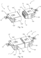
- FIGS. 1a and 1b show a connector module 1 and a mating connector module 1' that can be plugged into it and is basically constructed in a comparable manner, both in an unplugged state and in a plugged-in state.
- the connector module 1 and the mating connector module 1' are also referred to jointly as connector modules 1, 1' below.
- Each of these connector modules 1, 1' has an essentially cuboid-shaped insulating body 10, 10'.
- the connector modules 1, 1' each have a frame-shaped shielding element 15, 15', which surrounds the insulating body 10, 10' in a form-fitting manner.
- the shielding element 15, 15' is also essentially cuboid-shaped and has two narrow side walls 153' and two wide side walls 154' at right angles to this.
- the respective screen element 15, 15' further has on its narrow side walls 153, 153' in the Fig. 1b designated, inwardly directed locking tabs 151, 151' for its attachment to the insulating body 10, 10' and outwardly directed contact tabs 152, 152' for electrically contacting a connector modular frame 2, into which the connector modules can be inserted and in which they can be fixed by means of their locking lugs 122, 122', although this is only possible in the Fig. 5 is explicitly shown.
- each shielding element 15, 15' has an inwardly directed contact tab 156, 156' on one of its two opposing broad side walls 154, 154' for electrically contacting its essentially flat shielding transfer element 14, 14'.
- the shield transfer elements 14, 14' contact each other by means of their contact sections 141, 141', which in the Fig. 1a and thus also ensure a mutual ground connection of their shielding elements 15, 15'.
- the Fig. 2a and 2b show the connector modules 1, 1' in an exploded view.
- the connector modules 1, 1' each have a contact carrier 11, 11', several plug contacts 13, 13' and a holding plate 12, 12'. It is easy to imagine that the respective contact carrier 11, 11' and the associated holding plate 12, 12' are brought together and locked together in order to jointly form the respective insulating body 10, 10' shown in more detail below and thus to fix the plug contacts 13, 13' in continuous contact chambers 100, 100'.
- the plug contacts 13, 13' of the connector module 1 are designed as socket contacts 13 and those of the mating connector module 1' are designed as pin contacts 13'.
- locking lugs 121, 122' are formed on the narrow sides of the holding plates 12.
- the exploded view shows a substantially flat shield transfer element 14, 14' and a frame-shaped, cuboid shield element 15, 15' each as a separate individual part.
- Both the shield transfer element 14, 14' and the shield element 15, 15' are manufactured using a stamping and bending technique. While the shield transfer element 14, 14' is substantially flat, the shield element 15, 15' is bent at right angles on four edges and formed into a closed frame using a dovetail connection as a fastening means on two fastening edges that are thereby adjacent to one another.
- other fastening means are also known to those skilled in the art.
- the contact section 141 of the shield transfer element 14 of the connector module 1 is punched in a slightly forked shape and slightly bent for better contact with the flat contact section 141' of the shield transfer element 14' of the mating connector 1'. Therefore, the contact tabs of the contact section 141, which are not designated in more detail for reasons of clarity, have slight contact roundings. Nevertheless, both shield transfer elements 14, 14' are to be regarded as essentially flat.
- the shield transfer elements 14, 14' each have a cable connection area 142, 142'. This can be placed around the shield braid of a connected cable, for example, using pliers or another suitable tool and mechanically fastened to it and electrically connected to it by means of a crimp connection.
- the two insulating bodies 10, 10' made up of the respective contact carrier 11, 11' and the associated holding plate 12, 12', can be seen.
- the insulating bodies 10, 10' are essentially cuboid-shaped and consist of an electrically insulating material.
- the respective contact sections 141, 141' of the shield transfer elements 14, 14' can be seen on the side of the insulating bodies 10, 10' shown at the bottom of this drawing.
- the cable connection areas 142, 142' of the shield transfer elements 14, 14' can be seen to some extent.
- the insulating bodies 10, 10' have a cable connection side 127, 127' on their respective holding plate 12, 12'. Parallel to this, the insulating body 10, 10' has the aforementioned plug-in area 110, 110' with a plug-in side 111, 111' on its contact carrier 10, 10'.
- the plug-in side 111, 111' and the cable connection side 127, 127' are connected to one another via the contact chambers 100, 100' that run through the insulating body 10, 10'.
- the contact chambers 100, 100' serve to accommodate the plug contacts 13.
- the insulating bodies 10, 10' each have two perpendicular to the contact 111, 111' and cable connection side 127, 127' and broad sides 104, 104' lying parallel to one another and, at right angles thereto, two narrow sides 103, 103' lying parallel to one another.
- a locking lug 121, 122, 121', 122' is formed on each of the two narrow sides 103, 103', whereby only one locking lug 121, 122' can be seen in this illustration because the other locking lug 121', 122 is covered by the insulating body 10, 10'.
- the connector modules 1, 1' are each shown in two views.
- the corresponding insulating bodies 10, 10' are surrounded in a form-fitting manner on their wide sides 104 and narrow sides 103' by the 360° circumferential shielding element 15, 15', whereby the shielding element 15, 15' covers the largest part of the area - and thus more than 50% of the area - of the wide sides 104, 104' and the narrow sides 103, 103'.
- the respective shielding element 15, 15' is pushed onto the respective insulating body 10, 10' on the plug-in side.
- the shielding element 15, 15' is open on both the cable connection side 127, 127' and the plug-in side 111, 111' of the insulating body 10, 10'.
- the screen element 15, 15' is also essentially cuboid-shaped and has two narrow side walls 153' and, at right angles to them, two wide side walls 154'.
- the shielding element 15, 15' has inwardly directed locking tabs 151, 151' for fixing it to the insulating body 10, 10'.
- the shielding element 15, 15' has recesses 150, 150' on its narrow side walls 153, 153' at its cable connection side opening, which at least partially surround the locking lugs 121, 121', 122, 122' on three sides.
- the locking lugs 121, 121', 122, 122' of the connector modules 1, 1' protrude thus through the recesses 150, 150'. This is particularly advantageous because the locking lugs 121, 121', 122, 122' can thus fulfill their function despite the respective shield element 15, 15'.
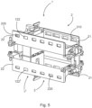
- This function is in the Fig. 5 can be seen particularly well. It consists in the locking lugs 121, 122, 121', 122' of the connector modules 1, 1' locking into locking windows 20, 20' of a connector modular frame 2. Due to their different sizes, they ensure the correct polarization, i.e. alignment, of the respective connector module 1, 1' in the connector modular frame 2.
- the connector modular frame 2 is an articulated frame that was manufactured using a zinc die-casting process.
- any other connector modular frame is equally suitable for this application, provided that it is at least partially made of metal in order to ensure the electrical conductivity required for the ground connection.
- each connector modular frame 2 has two opposing side walls 21, 22, which differ in the size of the locking windows 210, 220 arranged therein. It is easy to see that due to the different sized locking windows 210, 220, misorientation of the connector modules 1, 1' is prevented.
- the connector modules 1, 1' are not only in mutual plug contact, but are, as in the Fig. 1b As can be clearly seen, they are also electrically connected to one another over a large area with their shield transfer elements 14, 14' to improve shielding and/or grounding.
- the two shield transfer elements 14, 14' contact one another via their contact sections 141, 141'.
- the shielding elements 15, 15' contact the respective metallic connector modular frame 2 with their outward-facing contact tabs 152, 152' and the respective shielding transfer element 14, 14' with the inward-bent contact tabs 156, 156' and thus ensure grounding at several points and thus particularly good shielding against high-frequency interference fields.
Landscapes
- Engineering & Computer Science (AREA)
- Manufacturing & Machinery (AREA)
- Details Of Connecting Devices For Male And Female Coupling (AREA)
Description
- Die Erfindung geht aus von einem Steckverbindermodul nach der Gattung des unabhängigen Anspruchs 1.
- Die Erfindung geht weiterhin aus von einem Steckverbindermodularsystem, das einen metallischen oder zumindest teilweise metallischen Steckverbindermodularrahmen und zumindest ein Steckverbindermodul nach Anspruch 10 besitzt.
- Derartige Steckverbindermodule werden als Bestandteil eines Steckverbindermodularsystems benötigt, um einen Steckverbinder, insbesondere einen schweren Industriesteckverbinder, flexibel an bestimmte Anforderungen bezüglich der Signal- und Energieübertragung, z. B. zwischen zwei elektrischen Geräten, anpassen zu können. Dadurch können verschiedenste, z. B. optische und/oder elektrische analoge und/oder digitale Signale und/oder elektrische Energie je nach Bedarf flexibel zusammenstellbar über eine Steckverbindung übertragen werden.
- Üblicherweise werden dazu die entsprechenden Steckverbindermodule in dazu passende Steckverbindermodularrahmen, die mitunter auch als Halterahmen, Gelenkrahmen, Modulrahmen oder Modularrahmen bezeichnet werden, eingesetzt. Die Steckverbindermodularrahmen dienen somit dazu, mehrere zueinander gleichartige und/oder auch unterschiedliche Steckverbindermodule aufzunehmen und diese sicher an einer Fläche und/oder einer Gerätewand und/oder in einem Steckverbindergehäuse o. ä. zu befestigen.
- Die Steckverbindermodule besitzen in der Regel jeweils einen im Wesentlichen quaderförmigen Isolierkörper. Diese Isolierköper können beispielsweise zweiteilig ausgeführt sein und aus einem Kontaktträger und einer Halteplatte bestehen. Dadurch können sie in ihren Kontaktkammern Steckkontakte aufnehmen und darin fixieren.
- Die Steckkontakte unterschiedlicher Steckverbindermodule können dabei verschiedenster Art sein. Die Funktion eines dadurch gebildeten Steckverbinders ist also sehr flexibel. Es können z. B. pneumatische Module, optische Module, Module zur Übertragung elektrischer Energie und/oder elektrischer analoger und/oder digitaler Signale im jeweiligen Isolierkörper bzw. Gehäuse aufgenommen sein und so im Steckverbindermodularsystem Verwendung finden. Zunehmend übernehmen Steckverbindermodule auch mess- und datentechnische Aufgaben und sind daher besonders empfindlich gegenüber Störungen, insbesondere gegenüber elektrische und/oder magnetischen Störfeldern und Einstreuungen.
- Zum Halten mehrerer dieser Module im Steckverbindergehäuse werden in der Regel Steckverbindermodularrahmen verwendet. Diese können aus zwei gegeneinander schwenkbaren Rahmenhälften gebildet sein, die gelenkig miteinander verbunden sind. Die Steckverbindermodule sind mit an den Schmalseiten vorstehenden, etwa rechteckförmigen Rastnasen als Halterungs- und Polarisationsmittel zu ihrer Fixierung und korrekten Ausrichtung im Steckverbindermodularrahmen versehen.
- In den Seitenteilen der Rahmenhälften sind als allseitig geschlossene Öffnungen ausgebildete Ausnehmungen, nämlich sogenannte "Rastfenster" vorgesehen, in welche die Rastnasen beim Einfügen der Steckverbindermodule in den Steckverbindermodularrahmen formschlüssig eintauchen. Zum Einfügen der Steckverbindermodule wird der Steckverbindermodularrahmen aufgeklappt, d. h. geöffnet, wobei die Rahmenhälften um die Gelenke nur so weit aufgeklappt werden, dass die Steckverbindermodule eingesetzt werden können. Anschließend werden die Rahmenhälften zusammengekappt, d. h. der Steckverbindermodularrahmen wird geschlossen, wobei die Halterungsmittel in die Ausnehmungen gelangen und ein sicherer, formschlüssiger Halt der Steckverbindermodule in dem Steckverbindermodularrahmen bewirkt wird.
- Die Bauformen von Steckverbindermodularrahmen sind vielfältig. Es können beispielsweise auch Steckverbindermodularrahmen mit je einem starren Grundrahmen verwendet werden. Dieser kann insbesondere in einem Druckgussverfahren, z. B. im Zinkdruckgussverfahren, hergestellt sein und kann an seinen Längsseiten mit mehreren flexiblen Wangenteilen, z. B. mit Stanzbiegeteilen aus federelastischem Blech, versehen sein. Dabei können die Wangenteile Rastmittel wie Rastfenster oder Rasthaken oder dergleichen aufweisen, an denen die Steckverbindermodule z. B. mit ihren Rastnasen verrasten. Es können beispielsweise für jedes Steckverbindermodul zwei Wangenteile, also eins auf jeder Längsseite des Grundrahmens, vorgesehen sein oder es können auch ein- oder mehrere Wangenteile verwendet werden, die mehrere Laschen besitzen. An jedem Wangenteil und/oder jeder Lasche kann z. B. je ein Rastelement angeordnet sein. Solche Steckverbindermodularrahmen haben den Vorteil, dass die Steckverbindermodule mit nur geringem Aufwand, und beispielsweise auch automatisiert, einzeln in den Steckverbindermodularrahmen einführbar und daraus entnehmbar sind.
- Im Stand der Technik sind die besagten Steckverbindermodularsysteme mit derartigen Steckverbindermodulen unter Verwendung eines solchen Steckverbindermodularrahmens, auch als Halterahmen, Modulrahmen, Gelenkrahmen oder Modulrahmen bekannt, in zahlreichen Druckschriften und Veröffentlichungen in vielen verschiedenen Varianten offenbart, auf Messen gezeigt und befinden sich häufig im industriellen Umfeld in Form von Schwerlaststeckverbindern im Einsatz. Beispielsweise werden sie in den Druckschriften
DE 10 2013 106 279 A1 ,DE 10 2012 110 907 A1 ,DE 10 2012 107 270 A1 ,DE 20 2013 103 611 U1 ,EP 2 510 590 A1 ,EP 2 510 589 A1 ,DE 20 2011 050 643 U1 ,EP 0 860 906 A2 ,DE 29 601 998 U1 ,EP 1 353 412 A2 ,DE 10 2015 104 562 A1 ,EP 3 067 993 A1 ,EP 1 026 788 A1 ,EP 2 979 326 A1 ,EP 2 917 974 A1 beschrieben. - Aus der besagten Druckschrift
EP 0 860 906 B1 ist ein Steckverbindermodularrahmen in Form eines Gelenkrahmens zur Halterung von Steckverbindermodulen und zum Einbau in Steckverbindergehäuse oder zum Anschrauben an Wandflächen bekannt. Dabei sind die Steckverbindermodule in den Steckverbindermodularrahmen eingesetzt. An den Steckverbindermodulen sind Halterungsmittel vorgesehen, die mit an gegenüberliegenden Seitenteilen des Steckverbinderrnodularrahmens vorgesehenen Fenstern zusammenwirken, wobei die Fenster in rechteckigen Ausnehmungen bestehen, die als allseitig geschlossene Durchgangsöffnungen in den Seitenteilen des Steckverbindermodularrahmens ausgebildet sind. - Der Steckverbindermodularrahmen besteht in der Ausführung als Gelenkrahmen aus zwei gelenkig miteinander verbundenen Rahmenhälften, wobei die Trennung des Steckverbindermodularrahmen quer zu den Seitenteilen des Rahmens vorgesehen ist. In den Befestigungsenden des Steckverbindermodularrahmens sind Gelenke so angeordnet, dass sich die Seitenteile beim Aufschrauben des Steckverbindermodularrahmens auf eine Befestigungsfläche rechtwinklig zur Befestigungsfläche ausrichten, wodurch die Steckverbindermodule über die Halterungsmittel eine formschlüssige Verbindung mit dem Steckverbindermodularrahmen eingehen. In der Praxis sind solche Steckverbindermodularrahmen üblicherweise in einem Druckgussverfahren, insbesondere in einem Zinkdruckgussverfahren, gefertigt.
- Die Druckschrift
DE 10 2015 114 703 A1 offenbart eine Weiterentwicklung eines solchen als Gelenkrahmen ausgestalteten Steckverbindermodularrahmen. Der darin offenbarte Steckverbindermodularrahmen weist zumindest ein Fixierungsmittel auf, über welches die Rahmenhälften in zwei Positionen, einer offenen Position und einer geschlossenen Position, zueinander fixierbar sind, was die Handhabung erheblich vereinfacht. - Die Druckschrift
DE 20 2013 103 611 U1 zeigt zwei äußerst stabil miteinander verschraubbare, in Stanzbiegetechnik preiswert herstellbare und zusammenschraubbare Rahmenhälften, die zur Aufnahme von u. a. pneumatischen Modulen geeignet sind. Der so montierte Steckverbindermodularrahmen weist auch unter hoher mechanischer Langzeitbelastung nur sehr geringe Kriecheigenschaften auf. Nachteilig ist jedoch, dass der Aufwand zum Hinzufügen oder Auswechseln eines Steckverbindermoduls äußerst hoch ist. - Es hat sich in der Praxis jedoch gezeigt, dass solche Steckverbindermodularrahmen bei der Montage eine aufwändige Bedienung erfordern. Beispielsweise müssen solche Steckverbindermodularrahmen aus dem Steckverbindergehäuse herausgeschraubt und/oder entrastet werden, sobald auch nur ein einziges Modul ausgetauscht werden soll. Dabei fallen möglicherweise auch die anderen Steckverbindermodule, deren Entnahme gar nicht erwünscht war, aus dem Steckverbindermodularrahmen heraus und müssen dann vor dem Zusammenschrauben und/oder vor dem Verrasten der Rahmenhälften wieder eingefügt werden. Schließlich müssen sich bereits vor dem Zusammenfügen der Rahmenhälften alle Steckverbindermodule gleichzeitig in der für sie vorgesehenen Position befinden, um beim Zusammenfügen der Rahmenhälften endgültig im Steckverbindermodularrahmen fixiert zu werden, was die Montage erschwert.
- Die Druckschrift
EP 1 801 927 B1 offenbart einen einteiligen Steckverbindermodularrahmen, der aus Kunststoffmaterial besteht. Der Steckverbindermodularrahmen ist als umlaufender Kragen ausgebildet und weist an seiner Steckseite mehrere durch Schlitze getrennte Wandsegmente auf. Jeweils zwei gegenüberliegende Wandsegmente bilden einen Einfügebereich für ein Steckverbindermodul, wobei die Wandsegmente fensterartige Öffnungen aufweisen, die zur Aufnahme von an den Schmalseiten der Steckverbindermodule angeformten Vorsprüngen dienen. Weiterhin ist in den Wandsegmenten jeweils eine Führungsnut vorgesehen. Die Führungsnut ist oberhalb der Öffnungen mittels eines nach außen versetzten Fenstersteges gebildet, der auf der Innenseite eine Einführungsschräge aufweist. Zusätzlich weisen die Steckverbindermodule Rastarme auf, die an den Schmalseiten in Richtung der Kabelanschlüsse wirkend, angeformt sind, und unterhalb der seitlichen Kragenwand verrasten, so dass zwei unabhängige Rastmittel die Steckverbindermodule im Steckverbindermodularrahmen fixieren. Dieser Kunststoffrahmen hat den Nachteil, dass er keine PE-Schutzerdung ermöglicht, da er kein elektrisch leitendes Material aufweist
Die DruckschriftDE 10 2013 113 975 B4 offenbart einen Steckverbindermodularrahmen, insbesondere aus Zinkdruckguss, für einen schweren Steckverbinder zur Aufnahme gleichartiger und/oder unterschiedlicher Steckverbindermodule. Der Steckverbindermodularrahmen besteht aus einem im Querschnitt rechteckigen Grundrahmen, der zwei sich gegenüberliegenden Seitenteile aufweist. An den Seitenteilen ist jeweils ein Wangenteil, bestehend aus einem flexiblen Material, insbesondere federelastischem Blech, angebracht. Beim Einführen eines Steckverbindermoduls in den Steckverbindermodularrahmen senkrecht zur Rahmenebene werden diese Wangenteile zunächst vom Seitenteil weg nach außen gebogen. Insbesondere können die Wangenteile Laschen mit Rastfenstern, besitzen, welche dazu geeignet sind, die Steckverbindermodule an deren Rastnasen einzeln im Steckverbindermodularrahmen zu verrasten. Die Steckverbindermodule können somit einzeln und mit nur geringem Aufwand aus der Kabelanschlussrichtung und in Steckrichtung in den Steckverbindermodularrahmen eingeschoben und in umgekehrter Richtung wieder entnommen werden. Das eingesteckte Steckverbindermodul ist vom Grundrahmen des Steckverbindermodularrahmens in der Rahmenebene fest und stabil gehalten. In ihrer Einführrichtung, senkrecht zur Rahmenebene, können sie mit ihren Rastnasen jeweils zwischen einander gegenüberliegenden Wangenteilen verrasten. Diese Bauform hat grundsätzlich den Vorteil, dass die Steckverbindermodule einzeln eingesteckt und entnommen werden können, ohne dass die Befestigung der anderen Steckverbindermodule davon beeinträchtigt wird. Die Bauform gestattet es weiterhin, dass der Steckverbindermodularrahmen aus Metall besteht und einen PE-Kontakt aufweist oder mit einem solchen bestückt ist, und ermöglicht somit die Schutzerdung eines metallischen Steckverbindergehäuses, in welches der Steckverbindermodularrahmen eingeschraubt wird, sowie in einem gewissen Maße auch eine elektrisch und/oder magnetisch schirmende Funktion der Steckverbindermodule. - Grundsätzlich besteht im Stand der Technik der Nachteil, dass auch beim Einsatz metallischer Steckverbindermodularrahmen die elektrische Schirmung einzelner Steckverbindermodule nicht immer ausreichend ist.
- Dadurch können insbesondere elektrische Signale, die über Steckverbindermodule übertragen werden, durch elektrische und/oder magnetische Felder, die außerhalb des jeweiligen Steckverbindermoduls aber innerhalb des Steckverbindermodularrahmens entstehen, gestört werden. Solche Störungen können beispielsweise durch die eine elektrische Energieversorgung mit Wechselstrom. Weiterhin können auch außerhalb des Steckverbindermodularrahmens entstehende elektrische und/oder magnetische Felder die besagten elektrischen Signale innerhalb des Steckverbindermoduls stören.
- Für eine störstrahlungsfreie Übermittlung von Signalen schlägt die Druckschrift
EP 1 398 853 B1 dazu vor, dass ein Steckverbindermodul in einem aus isolierendem Material bestehenden Haltekörper ein elektrisch leitendes Schalengehäuse mit einem Steckereinsatz aufweist. Das Steckverbindermodul wird mittels Rastmitteln in einer Modulträgervorrichtung gehalten, die wiederum in ein Steckverbindergehäuse integriert ist. Innerhalb des Schalengehäuses ist eine elektrisch leitende Kontaktierung zu der Abschirmung eines signalführenden Kabels vorgesehen, so dass auch mehrere Steckverbindermodule, mit voneinander unabhängigen Erdpotenzialen sowie auch Steckverbindermodule, die eine Leistungsversorgung, Pneumatik oder dergleichen übertragen, ohne gegenseitige Beeinflussung in der Modulträgervorrichtung angeordnet sein können. - Bei dieser Bauform hat sich für viele Anwendungen als nachteilig erwiesen, dass keine Schirmübergabe und somit kein direkter Potentialausgleich des Schirms zwischen dem Steckverbindermodul und einem damit gesteckten Steckverbindermodul eines Gegensteckers vorhanden ist. Dies hat sich insbesondere für hochfrequente Signale als nachteilig herausgestellt.
- Um diesem Problem zu begegnen, offenbart die Druckschrift
DE 10 2018 108 968 A1 , dass beide miteinander gesteckten Steckverbindermodule jeweils ein Schirmübergabeelement aufweisen. Mit diesem Schirmübergabeelement ist ein kabelanschlussseitig an jedes Steckverbindermodul angeschlossenes Kabel, z. B. mit einem Schirmgeflecht, verbunden. Die Schirmübergabeelemente überdecken jeweils eine Seitenfläche des Steckverbindermoduls großflächig und sind steckseitig miteinander elektrisch kontaktierbar. Beide Schirmübergabeelemente bestehen aus einem metallischen Werkstoff, der insbesondere gute elektrisch leitende Eigenschaften hat. Durch diese Schirmübergabeelemente kann der Wellenwiderstand, auch Wellenimpedanz genannt, deutlich gesenkt werden. - Beim Betrieb dieser Bauform hat sich jedoch als nachteilig herausgestellt, dass der Querschnitt der Masseanbindung des angeschlossenen Kabels oft zu gering ist. Weiterhin ist dadurch immer noch kein direkter Potentialausgleich zwischen einem metallischen Steckverbindermodularrahmen und den Schirmübergabeelementen gewährleistet. Die aus dem Stand der Technik bekannten Schirmungen sind zumindest an den Schmalseiten der im Wesentlichen quaderförmigen Steckverbindermodule unterbrochen. Bereits auf dem Markt vorhandene Steckverbindermodule können mit den bekannten Schirmvorrichtungen nicht entsprechend nachgerüstet werden.
- Das Deutsche Patent- und Markenamt hat in der Prioritätsanmeldung zu vorliegender Anmeldung den folgenden Stand der Technik recherchiert:
DE 10 2015 015 189 B3 ,DE 20 2006 012 687 U1 ,DE 20 2018 101 278 U1 undWO 2010/ 113 524 A1 . - Dabei offenbart die Druckschrift
DE 20 2006 012 687 U1 ein modulares Steckverbindersystem mit wenigstens einem Steckermodul und einem Buchsenmodul zum Einsetzen in einen Rahmen eines Steckverbinders. Das Steckermodul und das Buchsenmodul werden zum Anschluss wenigstens eines abgeschirmten Kabels, mit jeweils einem Gehäuse, ersten Anschlüssen und vorzugsweise mit zweiten Anschlüssen, die beim Zusammenstecken des Steckermoduls und des Buchsenmoduls leitend miteinander verbunden. Die ersten Anschlüsse sind vorzugsweise über Stromschienen leitend mit einem Stecker und einer Buchse am Stecker- und Buchsenmodul verbunden. Weiterhin wird offenbart, dass sowohl das Steckermodul als auch das Buchsenmodul jeweils zwei Schirmbleche mit Abwinklungen aufweisen, wobei die Abwinklungen sich in voneinander abgewandte Richtungen am Steckermodul und am Buchsenmodul erstrecken. - Die Aufgabe der Erfindung besteht darin, die Schirmung eines Steckverbindermoduls und eines damit ausgestatteten Steckverbindermodularsystems zu verbessern, um dadurch eine besonders hohe Qualität der durch das Steckverbindermodul übertragenen elektrischen Signale zu gewährleisten und insbesondere den negativen Einfluss hochfrequenter elektrischer und/oder magnetischer Störfelder auf die Signalqualität dieser Signale zu minimieren.
- Die Aufgabe wird durch den Gegenstand der unabhängigen Ansprüche gelöst.
- Ein Steckverbindermodul weist einen im wesentlichen quaderförmigen Isolierkörper aus einem elektrisch isolierendem Material auf.
- Weiterhin besitzt es eine Steckseite und dazu parallel gegenüberliegend eine Kabelanschlussseite. Die Kabelanschlussseite und die Steckseite sind miteinander über durchgehenden Kontaktkammern verbunden. Die Kontaktkammern dienen zur Aufnahme elektrisch leitender Steckkontakte.
- Weiterhin besitzt der Isolierkörper zwei senkrecht zu seiner Kabelanschluss- und Steckseite verlaufende und einander parallel gegenüberliegende Breitseiten und rechtwinklig dazu zwei einander parallel gegenüberliegenden Schmalseiten. An jede dieser beiden Schmalseiten ist jeweils eine Rastnase zur Fixierung des Steckverbindermoduls in einem Steckverbindermodularrahmen angeformt. Diese beiden einander gegenüberliegenden Rastnasen unterscheiden sich voneinander in ihrer Form und/oder Größe, um so als Polarisationsmittel eine korrekte Orientierung des Steckverbindermoduls im Steckverbindermodularrahmen zu gewährleisten.
- Das Steckverbindermodul ist an seinen Breit- und Schmalseiten von einem umlaufenden Schirmelement formschlüssig umgeben, wobei das Schirmelement jeweils mehr als 50% der Fläche der Breit- und der Schmalseiten abdeckt. Dies bedeutet, dass das Schirmelement mehr als 50% der beiden Breitseiten abdeckt und dass das Schirmelement mehr als 50% der beiden Schmalseiten abdeckt. Weiterhin ist das Schirmelement sowohl an der Kabelanschlussseite als auch an der Steckseite des Moduls offen ausgeführt. Das Schirmelement besitzt also an der Kabelanschlussseite und an der Steckseite des Isolierkörpers Öffnungen.
- Ein Steckverbindermodularsystem besitzt einen zumindest teilweise metallischen Steckverbindermodularrahmen und ein solches Steckverbindermodul, wobei das Schirmelement zur Herstellung einer zusätzlichen elektrisch leitenden Verbindung zu dem Steckverbindermodularrahmen an zumindest einer seiner Schmalseitenwände zumindest eine nach außen gerichtete Kontaktlasche aufweist und mit dem Steckverbindermodularrahmen über diese nach außen gerichtete Kontaktlasche in elektrischer Verbindung steht.
- Vorteilhafte Ausgestaltungen der Erfindung sind in den Unteransprüchen und der folgenden Beschreibung angegeben.
- Die Erfindung hat den Vorteil, dass die durch das Steckverbindermodul übertragenen Signale durch außerhalb des Steckverbindermoduls entstehende elektrische und/oder magnetische Felder nicht gestört werden oder dass eine solche Störung zumindest weitgehend unterdrückt wird.
- In einer bevorzugten Ausgestaltung weist das Steckverbindermodul zumindest einen elektrischen Steckkontakt mit einem Kabelanschlussabschnitt und einem Steckabschnitt auf. Der Steckkontakt ist in zumindest eine Kontaktkammer des Isolierkörpers eingefügt. Sein Kabelanschlussabschnitt ist von der Kabelanschlussseite des Isolierkörpers zugänglich, um vorteilhafterweise das Anschließen eines elektrischen Leiters eines Kabels zu ermöglichen, und sein Steckabschnitt ragt in den Steckbereich des Isolierkörpers hinein, um vorteilhafterweise eine Steckverbindung mit einem Gegenstecker zu ermöglichen.
- In einer vorteilhaften Ausgestaltung ist das Schirmelement im Wesentlichen als ein quaderförmiger Rahmen ausgeführt ist, welcher, korrespondierend mit der Quaderform des Steckverbindermoduls, zwei einender gegenüberliegende Schmalseitenwände und rechtwinklig dazu zwei einander gegenüberliegende Breitseitenwände aufweist. Dies ist besonders vorteilhaft, weil dadurch das Schirmelement insbesondere aus steckseitiger Richtung und bevorzugt passgenau auf das Steckverbindermodul aufgeschoben werden kann. Vorteilhafterweise können sowohl dafür vorgesehene Steckverbindermodule als auch eine Vielzahl bereits auf dem Markt existierender Steckverbindermodule in dieser Weise mit einem solchen Schirmelement versehen werden.
- Bevorzugt besitzt das Schirmelement besitzt an seiner kabelanschlussseitigen Öffnung an den Schmalseitenwänden Aussparungen, welche die Rastnasen zumindest teilweise dreiseitig umgreifen. Die Rastnasen der Steckverbindermodule ragen dann durch die Aussparungen zumindest teilweise hindurch. Dies ist besonders vorteilhaft, weil die Rastnasen auf diese Weise trotz des Schirmelements ihre Funktion erfüllen können, die darin besteht, am Steckverbindermodularrahmen zu verrasten und für die korrekte Polarisation, d. h. Ausrichtung, des Steckverbindermoduls, im Steckverbindermodularrahmen zu sorgen.
- In einer weiteren bevorzugten Ausgestaltung kann das Schirmelement aus einem Blechteil bestehen. Insbesondere kann es als Stanzbiegeteil ausgeführt und an vier parallelen Biegekanten rechtwinklig gebogen sein. Weiterhin kann das Schirmelement an zwei dadurch aneinander angrenzenden Befestigungskanten Befestigungsmittel zu deren gegenseitiger Befestigung besitzt, so dass das Schirmelement besonders vorteilhaft zu einer geschlossenen, d. h. umlaufenden Form, insbesondere dem besagten quaderförmigen Rahmen, geformt ist.
- Diese Befestigungsmittel können vorzugsweise in einer besonders unaufwändig herstellbaren und zudem stabilen Schwalbenschwanzverbindung bestehen.
- Insbesondere kann es sich bei dem Schirmelement um ein Stanzbiegeteil handeln, welches sich vorteilhafterweise preisgünstig und unaufwändig herstellen und zur Schirmung verwenden lässt.
- Erfindungsgemäß weist das Steckverbindermodul zusätzlich zum bevorzugt einstückigen Schirmelement auch noch zumindest ein, in einer weiteren Ausgestaltung mehrere, beispielsweise zwei Schirmübergabeelemente auf. Dieses mindestens eine Schirmübergabeelement kann an einer der beider Breitseiten des Steckverbindermoduls angeordnet sein. Dafür kann das Steckverbindermodul an seiner entsprechenden Breitseite in einer vorteilhaften Ausgestaltung je eine entsprechende Ausnehmung aufweisen, in welche sich das Schirmübergabeelement bevorzugt formschlüssig einlegen lässt. Dies hat den Vorteil, dass sich das quaderförmige Schirmelement problemlos auf das mit dem mindestens einen Schirmübergabeelement versehene Steckverbindermodul aufschieben lässt, ohne dabei durch dieses behindert zu werden.
- Das mindestens eine Schirmübergabeelement kann aus Blech gebildet sein. Insbesondere kann es sich um ein Stanzbiegeteil handeln. Das Schirmübergabeelement kann im Wesentlichen flächig ausgeführt sein. Dies bedeutet, dass insbesondere ein Kontaktbereich des Schirmübergabeelements zur Kontaktierung eines Kontaktübergabeelements eines Gegensteckers aus einer Hauptebene des Schirmübergabeelements geringfügig herausgeborgen sein kann, z. B. in Form einer leichten Rundung zur großflächigen elektrischen Kontaktierung mit einer Kontaktfläche eines Schirmübergabeelements des Gegensteckers.
- Auch kann das im Wesentlichen flächig ausgebildete Schirmübergabeelement zur Masseanbindung an das Kabel kabelanschlussseitig einen Schirmanbindungsbereich aufweisen, der beispielsweise in Form eines Quetschkontaktes/ Crimpkontaktes um den Schirm des Kabels herumgelegt und mittels eines Werkzeugs, z. B. einer Zange zusammengepresst sein kann.
- In einer bevorzugten Ausgestaltung kann das Schirmelement zur Herstellung des elektrischen Kontakts mit dem Schirmübergabeelement zumindest eine, bevorzugt mehrere nach innen gebogene Kontaktlaschen aufweisen. Dies ist vorteilhaft, weil dadurch ein gemeinsamer Massekontakt insbesondere im Sinne einer gemeinsamen Erdung an möglichst vielen Kontaktbereichen, zur Erzeugung einer auch für hochfrequente Störsignale besonders guten Schirmung herstellbar ist. Diese nach innen gerichteten Kontaktlaschen können vorteilhafterweise in einer Breitseitenwand angeordnet sein, weil sie dann zum einen das darunterliegende Schirmübergabeelement direkt kontaktieren können. Außerdem kann diese von Vorteil sein, weil dadurch in den Schmalseitenwänden ausreichend Platz verbleibt, um dort z. B. nach außen gerichtete Kontaktlaschen zur Kontaktierung eines metallischen Steckverbindermodularrahmens und/oder nach innen gerichtete Rastlaschen zur Verrastung des Schirmelements am Steckverbindermodul anzuordnen. Letztere sind besonders vorteilhaft an der Schmalseite des Steckverbindermoduls verrastet, weil diese Schmalseiten bevorzugt frei von dem Schirmübergabeelement sind, so dass die Verrastung nicht durch diese behindert werden kann.
- Das Schirmelement ist somit mehrfach geerdet und kann dadurch den Einfluss insbesondere hochfrequenter elektrischer und/oder magnetischer Felder auf die durch das Steckverbindermodul übertragenen elektrischen Signale besonders gut unterdrücken.
- Ein Ausführungsbeispiel der Erfindung ist in den Zeichnungen dargestellt und wird im Folgenden näher erläutert. Es zeigen:
- Fig. 1a, b
- zwei Steckverbindermodule in ungestecktem und gestecktem Zustand;
- Fig. 2a, b
- die beiden Steckverbindermodule in je einer Explosionsdarstellung;
- Fig. 3a, b
- zwei Isolierkörper der Steckverbindermodule;
- Fig. 4a, b
- die Steckverbindermodule mit je einem Schirmelement;
- Fig. 5
- zwei miteinander gesteckte Steckverbindermodularsysteme mit je einem Steckverbindermodularrahmen und einem Steckverbindermodul.
- Die Figuren enthalten teilweise vereinfachte, schematische Darstellungen. Zum Teil werden für gleiche, aber gegebenenfalls nicht identische Elemente identische Bezugszeichen verwendet. Verschiedene Ansichten gleicher Elemente könnten unterschiedlich skaliert sein.
- Die
Figur 1a und 1b zeigen ein Steckverbindermodul 1 und ein damit steckbares und grundsätzlich damit vergleichbar aufgebautes Gegensteckermodul 1' sowohl in einem ungesteckten als auch in einem miteinander gesteckten Zustand. Zur verbalen Vereinfachung werden das Steckverbindermodul 1 und das Gegensteckermodul 1' im Folgenden auch gemeinsam als Steckverbindermodule 1, 1' bezeichnet. - Jedes dieser Steckverbindermodule 1, 1' besitzt einen im Wesentlichen quaderförmigen Isolierkörper 10, 10'.
- Die Steckverbindermodule 1,1 ' besitzen weiterhin jeweils ein rahmenförmiges Schirmelement 15, 15', welches den Isolierkörper 10, 10' formschlüssig umgreift. Das Schirmelement 15, 15' ist dazu ebenfalls im Wesentlichen quaderförmig ausgeführt und besitzt zwei Schmalseitenwände 153' und rechtwinklig dazu zwei Breitseitenwände 154'.
- Das jeweilige Schirmelement 15, 15' besitzt weiterhin an seinen Schmalseitenwänden 153, 153' in der
Fig. 1b bezeichnete, nach innen gerichtete Rastlaschen 151, 151' zu seiner Befestigung an dem Isolierkörper 10, 10' und nach außen gerichtete Kontaktlaschen 152, 152' zur elektrischen Kontaktierung eines Steckverbindermodularrahmens 2, in welchen die Steckverbindermodule einfügbar und in dem sie mittels ihrer Rastnasen 122, 122' fixierbar sind, wobei dies aber erst in derFig. 5 explizit gezeigt wird. - Zudem besitzt jedes Schirmelement 15, 15' an einer seiner beiden einander gegenüberliegenden Breitseitenwände 154, 154' eine nach innen gerichtete Kontaktlasche 156, 156' zur elektrischen Kontaktierung seines im Wesentlichen flächigen Schirmübergabeelements 14, 14'.
- In dem in der
Fig. 1b gezeigten, gesteckten Zustand kontaktieren die Schirmübergabeelemente 14, 14' miteinander mittels ihrer Kontaktabschnitte 141, 141', welche in derFig. 1a bezeichnet sind, und sorgen so auch für eine gegenseitige Masseanbindung ihrer Schirmelemente 15, 15'. - Die
Fig. 2a und 2b zeigen die Steckverbindermodule 1, 1' jeweils in einer Explosionsdarstellung. Die Steckverbindermodule 1, 1' besitzen jeweils einen Kontaktträger 11, 11', mehrere Steckkontakte 13, 13' sowie eine Halteplatte 12, 12'. Es ist leicht vorstellbar, dass der jeweilige Kontaktträger 11, 11' und die dazugehörige Halteplatte 12, 12' zusammengeführt und aneinander verrastet werden, um gemeinsam den jeweiligen, im Folgenden noch näher gezeigten Isolierkörper 10, 10' zu bilden und so die Steckkontakte 13, 13' in durchgehenden Kontaktkammern 100, 100' zu fixieren. - Im vorliegenden Beispiel sind die Steckkontakte 13, 13' des Steckverbindermoduls 1 als Buchsenkontakte 13 und die des Gegensteckermoduls 1' als Stiftkontakte 13' ausgeführt.
- Weiterhin sind an den Halteplatten 12 schmalseitig Rastnasen 121, 122' angeformt.
- Außerdem ist in der Explosionsdarstellung jeweils ein im wesentlichen flächiges Schirmübergabeelement 14, 14' und ein rahmenförmiges, quaderförmiges Schirmelement 15, 15' je als separates Einzelteil gezeigt. Sowohl das Schirmübergabeelement 14, 14' als auch das Schirmelement 15, 15' sind mittels einer Stanzbiegetechnik hergestellt. Während das Schirmübergabeelement 14, 14' aber im Wesentlichen flächig ausgeführt ist, ist das Schirmelement 15, 15' an vier Kanten rechtwinklig abgebogen und an zwei dadurch aneinander angrenzenden Befestigungskanten mittels einer Schwalbenschwanzverbindung als Befestigungsmittel zu einem geschlossenen Rahmen geformt. Selbstverständlich sind dem Fachmann dazu auch andere Befestigungsmittel bekannt.
- Der Kontaktabschnitt 141 des Schirmübergabeelements 14 des Steckverbindermoduls 1 ist leicht gabelförmig gestanzt und zur besseren Kontaktierung mit dem ebenen Kontaktabschnitt 141' des Schirmübergabeelements 14' des Gegensteckers 1' geringfügig gebogen. Daher weisen die, aus Übersichtlichkeitsgründen nicht näher bezeichneten Kontaktlaschen des Kontaktabschnitts 141, leichte Kontaktrundungen auf. Dennoch sind beide Schirmübergabeelemente 14, 14' als im Wesentlichen flächig anzusehen.
- Kabelanschlussseitig besitzen die Schirmübergabeelemente 14, 14' jeweils einen Kabelanschlussbereich 142, 142'. Diese lässt sich beispielsweise mit einer Zange oder einem anderen geeigneten Werkzeug um das Schirmgeflecht eines angeschlossenen Kabels legen und mittels einer Quetschverbindung mechanisch daran befestigen und elektrisch damit verbinden.
- In den
Fig. 3a und 3b sind die beiden aus dem jeweiligen Kontaktträger 11, 11' und der dazugehörigen Halteplatte 12, 12' zusammengesetzten Isolierkörper 10, 10' zu sehen. Die Isolierkörper 10, 10' sind im Wesentlichen quaderförmig ausgeführt und bestehen aus einem elektrisch isolierendem Material. An der, in dieser Zeichnung unten dargestellten Seite der Isolierkörper 10, 10' sind die jeweiligen Kontaktabschnitte 141, 141' der Schirmübergabeelemente 14, 14' zu erkennen. Kabelanschlussseitig sind jeweils die Kabelanschlussbereiche 142, 142' der Schirmübergabeelemente 14, 14' ansatzweise zu sehen. - Die Isolierkörper 10, 10' besitzen an ihrer jeweiligen Halteplatte 12, 12' eine Kabelanschlussseite 127, 127'. Dazu parallel gegenüberliegend besitzt der Isolierkörper 10, 10' an seinem Kontaktträger 10, 10' den besagten Steckbereich 110, 110' mit einer Steckseite 111, 111'. Die Steckseite 111, 111' und die Kabelanschlussseite 127, 127' sind über die durch den Isolierkörper 10, 10' durchgehenden Kontaktkammern 100, 100' miteinander verbunden. Die Kontaktkammern 100, 100' dienen zur Aufnahme der Steckkontakte 13.
- Weiterhin besitzen die Isolierkörper 10, 10' jeweils zwei senkrecht zur Kontakt- 111, 111' und Kabelanschlussseite 127, 127'verlaufende und einander parallel gegenüberliegende Breitseiten 104, 104' und rechtwinklig dazu zwei einander parallel gegenüberliegende Schmalseiten 103, 103'. An jede der beiden Schmalseiten 103, 103' ist jeweils eine Rastnase 121, 122, 121', 122' angeformt, wobei in dieser Darstellung jeweils nur eine Rastnase 121, 122' zu sehen ist, weil die jeweils andere Rastnase 121', 122 vom Isolierkörper 10, 10' verdeckt ist.
- In den
Fig. 4a und 4b sind die Steckverbindermodule 1, 1' jeweils in zwei Ansichten gezeigt. Die dazugehörigen Isolierkörper 10, 10' sind an ihren Breit- 104 und Schmalseiten 103' von dem 360° umlaufenden Schirmelement 15, 15' formschlüssig umgeben, wobei das Schirmelement 15, 15' jeweils den größten Teil der Fläche - und somit mehr als 50% der Fläche - der Breit- 104, 104' und der Schmalseiten 103, 103' abdeckt. Dazu ist das jeweilige Schirmelement 15, 15' steckseitig auf den jeweiligen Isolierkörper 10, 10' geschoben. Weiterhin ist das Schirmelement 15, 15' sowohl an der Kabelanschlussseite 127, 127'als auch an der Steckseite 111, 111' des Isolierkörpers 10, 10' offen ausgeführt. - Das Schirmelement 15, 15' ist dazu ebenfalls im Wesentlichen quaderförmig ausgeführt und besitzt zwei Schmalseitenwände 153' und rechtwinklig dazu zwei Breitseitenwände 154'.
- An den Schmalseitenwänden 153, 153' besitzt das Schirmelement 15, 15' nach innen gerichtete Rastlaschen 151, 151' zu seiner Fixierung an dem Isolierkörper 10, 10'.
- Außerdem besitzt das Schirmelement 15, 15' an seinen Schmalseitenwänden 153, 153' an seiner kabelanschlussseitigen Öffnung Aussparungen 150, 150', welche die Rastnasen 121, 121', 122, 122' zumindest teilweise dreiseitig umgreifen. Die Rastnasen 121, 121', 122, 122' der Steckverbindermodule 1, 1' ragen somit durch die Aussparungen 150, 150' hindurch. Dies ist besonders vorteilhaft, weil die Rastnasen 121, 121', 122, 122' auf diese Weise trotz des jeweiligen Schirmelements 15, 15' ihre Funktion erfüllen können.
- Diese Funktion ist in der
Fig. 5 besonders gut zu sehen. Sie besteht darin, dass die Rastnasen 121, 122, 121', 122' des Steckverbindermodule 1, 1' an Rastfenstern 20, 20' eines Steckverbindermodularrahmens 2 verrasten. Durch ihre unterschiedliche Größe sogen sie dabei für die korrekte Polarisation, d. h. Ausrichtung, des jeweiligen Steckverbindermoduls 1, 1' im Steckverbindermodularrahmen 2. Bei dem Steckverbindermodularrahmen 2 handelt es sich in diesem Fall um einen Gelenkrahmen, der in einem Zinkdruckgussverfahren hergestellt wurde. Es ist dem Fachmann jedoch klar, dass auch jeder andere Steckverbindermodularrahmen in gleicher Weise für diese Anwendung geeignet ist, sofern er zumindest teilweise aus Metall besteht, um die zur Masseverbindung notwendige elektrische Leitfähigkeit zu gewährleisten. - In dieser Darstellung sind zwei gleiche Steckverbindermodularrahmen 2 gezeigt, von den einer das Steckverbindermodul 1 und der andere das Gegensteckverbindermodul 1' beherbergt. Jeder Steckverbindermodularrahmen 2 besitzt zwei einander gegenüberstehende Seitenwände 21, 22, die sich durch die Größe der darin angeordneten Rastfenster 210, 220 unterscheiden. Es ist leicht erkennbar, dass aufgrund der verschiedenen großen Rastfenster 210, 220 eine Fehlorientierung der Steckverbindermodule 1,1' verhindert ist.
- Die Steckverbindermodule 1, 1' stehen nicht nur in gegenseitigem Steckkontakt, sondern sind, wie auch in der
Fig. 1b gut zu sehen ist, zudem zur Verbesserung der Schirmung und/oder Erdung mit ihren Schirmübergabeelementen 14, 14' auch großflächig elektrisch miteinander verbunden. Die beiden Schirmübergabeelemente 14, 14' kontaktieren dazu miteinander über ihre Kontaktabschnitte 141, 141'. - Zudem kontaktieren die Schirmelemente 15, 15' mit ihren nach außen gerichteten Kontaktlaschen 152, 152' den jeweiligen metallischen Steckverbindermodularrahmen 2 und mit den nach innen gebogenen Kontaktlaschen 156, 156' das jeweilige Schirmübergabeelement 14, 14' und sorgen so für eine Erdung an mehreren Stellen und damit für eine besonders gute Schirmung gegen hochfrequente Störfelder.
- Auch wenn in den Figuren verschiedene Aspekte oder Merkmale der Erfindung jeweils in Kombination gezeigt sind, ist für den Fachmann - soweit nicht anders angegeben - ersichtlich, dass die dargestellten und diskutierten Kombinationen nicht die einzig möglichen sind. Insbesondere können einander entsprechende Einheiten oder Merkmalskomplexe aus unterschiedlichen Ausführungsbeispielen miteinander ausgetauscht werden.
-
- 1, 1'
- Steckverbindermodule; (Steckverbindermodul, Gegensteckermodul)
- 10, 10'
- Isolierkörper
- 100, 100'
- Kontaktkammern
- 103, 103'
- Schmalseite
- 104, 104'
- Breitseite
- 11, 11'
- Kontaktträger
- 110, 110'
- Steckbereich
- 111, 111'
- Steckseite
- 12, 12'
- Halteplatte
- 121, 121', 122, 122'
- Rastnasen
- 127, 127'
- Kabelanschlussseite
- 13, 13'
- Steckkontakte (Buchsenkontakte, Stiftkontakte)
- 14, 14'
- Schirmübergabeelement
- 141, 141'
- Kontaktabschnitt des Schirmübergabeelements
- 142, 142'
- Kabelanschlussbereich des Schirmübergabeelements
- 15, 15'
- Schirmelement
- 150, 150'
- Aussparungen
- 151, 151'
- Rastlaschen des Schirmelements
- 152, 152'
- nach außen gerichtete Kontaktlaschen
- 153, 153'
- Schmalseitenwand
- 154, 154'
- Breitseitenwand
- 156, 156'
- nach innen gerichtete Kontaktlaschen
- 2
- Steckverbindermodularrahmen
- 21, 22
- Seitenwände des Steckverbindermodularrahmens
- 210, 220
- Rastfenster des Steckverbindermodularrahmens
Claims (12)
- Steckverbindermodul (1, 1'), aufweisend einen im wesentlichen quaderförmigen Isolierkörper (10, 10') aus einem elektrisch isolierenden Material, wobei der Isolierkörper (10, 10') einen Steckbereich (110, 110') mit einer Steckseite (111, 111') und dazu parallel gegenüberliegend eine Kabelanschlussseite (127, 127') besitzt, wobei die Kabelanschlussseite (127, 127') und die Steckseite (111, 111') miteinander über durchgehenden Kontaktkammern (100, 100') zur Aufnahme elektrisch leitender Steckkontakte (13, 13') verbunden sind, wobei der Isolierkörper (10, 10') weiterhin zwei senkrecht zu seiner Kabelanschluss- (102, 102') und Steckseite (111, 111') verlaufende und einander parallel gegenüberliegende Schmalseiten (103, 103') und rechtwinklig dazu zwei einander parallel gegenüberliegende Breitseiten (104, 104') besitzt, wobei an jede Schmalseite jeweils eine Rastnase (121, 121', 122, 122') zur Fixierung des Steckverbindermoduls (1, 1') in einem Steckverbindermodularrahmen (2) angeformt ist, wobei sich diese beiden einander gegenüberliegenden Rastnasen (121, 121', 122, 122') in ihrer Form und/oder Größe unterscheiden, um so als Polarisationsmittel eine korrekte Orientierung des Steckverbindermoduls (1, 1') im Steckverbindermodularrahmen (2) zu gewährleisten, dadurch gekennzeichnet, dass das Steckverbindermodul (1, 1') weiterhin an seinen Breit- (104, 104') und Schmalseiten (103, 103') von einem umlaufenden Schirmelement (15, 15') formschlüssig umgeben ist, wobei das Schirmelement (15, 15') mehr als 50% der beiden Breitseiten (104, 104') abdeckt und dass das Schirmelement mehr als 50% der beiden Schmalseiten (103, 103') abdeckt und sowohl an der Kabelanschlussseite (127, 127') als auch an der Steckseite (111, 111') des Isolierkörpers (10, 10') jeweils eine Öffnung besitzt, wobei das Steckverbindermodul (1, 1') zusätzlich zum Schirmelement (15, 15') an zumindest einer seiner beider Breitseiten (104, 104') weiterhin mindestens ein separates Schirmübergabeelement (14, 14') aufweist, welches mit dem Schirmelement (15, 15') in elektrischem Kontakt steht.
- Steckverbindermodul (1, 1') gemäß Anspruch 1, dadurch gekennzeichnet, dass das Steckverbindermodul (1, 1') zumindest einen elektrischen Steckkontakt (13, 13') mit einem Kabelanschlussabschnitt und einem Steckabschnitt aufweist, der in eine der Kontaktkammern (100, 100') des Isolierkörpers (10, 10') eingefügt ist, wobei sein Kabelanschlussabschnitt von der Kabelanschlussseite (127, 127') des Isolierkörpers (10, 10') zugänglich ist und wobei sein Steckabschnitt in den Steckbereich (110, 110') des Isolierkörpers (10, 10') hineinragt.
- Steckverbindermodul (1, 1') gemäß einem der vorstehenden Ansprüche, dadurch gekennzeichnet, dass das Schirmelement (15, 15') im Wesentlichen als ein quaderförmiger Rahmen ausgeführt ist, welcher, korrespondierend mit der Quaderform des Steckverbindermoduls (1, 1'), zwei einender gegenüberliegende Schmalseitenwände (153, 153') und rechtwinklig dazu zwei einander gegenüberliegende Breitseitenwände (154, 154') aufweist.
- Steckverbindermodul (1, 1') gemäß einem der vorstehenden Ansprüche, dadurch gekennzeichnet, dass das Schirmelement (15, 15') an seiner kabelanschlussseitigen Öffnung an seinen Schmalseitenwänden (153, 153') Aussparungen (150, 150') besitzt, welche die Rastnasen (121, 121', 122, 122') zumindest teilweise dreiseitig umgreifen, wodurch die Rastnasen (121, 121', 122, 122') der Steckverbindermodule (1, 1') zumindest teilweise durch die Aussparungen (150, 150') hindurchragen.
- Steckverbindermodul (1, 1') gemäß einem der vorstehenden Ansprüche, dadurch gekennzeichnet, dass das Schirmelement (15, 15') aus einem Blechteil besteht, welches als Stanzbiegeteil ausgeführt und an vier parallelen Biegekanten rechtwinklig gebogen ist, wobei das Schirmelement (15, 15') an zwei dadurch aneinander angrenzenden Befestigungskanten Befestigungsmittel zu deren gegenseitiger Befestigung und damit zur Herstellung einer geschlossenen Rahmenform besitzt.
- Steckverbindermodul (1, 1') gemäß Anspruch 5, dadurch gekennzeichnet, dass es sich bei dem Schirmelement (15, 15') um ein Stanzbiegeteil handelt.
- Steckverbindermodul (1, 1') gemäß einem der vorstehenden Ansprüche, dadurch gekennzeichnet, dass das mindestens eine Schirmübergabeelement (14, 14') einstückig als Stanzbiegeteil aus Blech gebildet und im Wesentlichen flächig ausgeführt ist.
- Steckverbindermodul (1, 1') gemäß einem der vorstehenden Ansprüche, dadurch gekennzeichnet, dass das mindestens eine Schirmübergabeelement (14, 14') zur Masseanbindung an das Kabel kabelanschlussseitig einen Kabelanschlussbereich (142, 142') aufweist.
- Steckverbindermodul (1, 1') gemäß einem der vorstehenden Ansprüche, dadurch gekennzeichnet, dass das Schirmelement (15, 15') zur Herstellung des elektrischen Kontakts mit dem Schirmübergabeelement (14, 14') an zumindest einer seiner Breitseitenwände (154, 154') nach innen gebogene Kontaktlaschen (156, 156') aufweist.
- Steckverbindermodul (1, 1') gemäß einem der vorstehenden Ansprüche, wobei das Schirmelement (15, 15') zur Herstellung einer zusätzlichen elektrisch leitenden Verbindung zu einem zumindest teilweise metallischen Steckverbindermodularrahmen (2) an zumindest einer seiner Schmalseitenwände (153, 153') zumindest eine nach außen gerichtete Kontaktlasche (152, 152') aufweist.
- Steckverbindermodularsystem, aufweisend einen zumindest teilweise metallischen Steckverbindermodularrahmen (2) und zumindest ein darin angeordnetes und fixiertes Steckverbindermodul (1, 1') gemäß Anspruch 10, dadurch gekennzeichnet, dass das Schirmelement (15, 15') mit dem Steckverbindermodularrahmen (2) über die nach außen gerichtete Kontaktlasche (152, 152') in elektrischer Verbindung steht.
- Steckverbindermodularsystem gemäß Anspruch 11, dadurch gekennzeichnet, dass das mindestens eine Steckverbindermodul (1, 1') im Steckverbindermodularrahmen (2) dadurch fixiert und zudem in einer vorgegebenen Ausrichtung polarisiert ist, dass seine Rastnasen (121, 121', 122, 122') formschlüssig in verschieden große Rastfenster (210, 220) eingreifen, welche der Steckverbindermodularrahmen (2) an zwei einander gegenüberliegenden Seitenwänden (21, 22) aufweist.
Applications Claiming Priority (2)
| Application Number | Priority Date | Filing Date | Title |
|---|---|---|---|
| DE102020107725.4A DE102020107725B3 (de) | 2020-03-20 | 2020-03-20 | Geschirmtes Steckverbindermodul |
| PCT/DE2021/100247 WO2021185410A1 (de) | 2020-03-20 | 2021-03-10 | Geschirmtes steckverbindermodul |
Publications (2)
| Publication Number | Publication Date |
|---|---|
| EP4122056A1 EP4122056A1 (de) | 2023-01-25 |
| EP4122056B1 true EP4122056B1 (de) | 2025-02-19 |
Family
ID=75267440
Family Applications (1)
| Application Number | Title | Priority Date | Filing Date |
|---|---|---|---|
| EP21714811.3A Active EP4122056B1 (de) | 2020-03-20 | 2021-03-10 | Geschirmtes steckverbindermodul |
Country Status (7)
| Country | Link |
|---|---|
| US (1) | US12308576B2 (de) |
| EP (1) | EP4122056B1 (de) |
| KR (1) | KR102711117B1 (de) |
| CN (1) | CN115398755B (de) |
| DE (2) | DE102020107725B3 (de) |
| PL (1) | PL4122056T3 (de) |
| WO (1) | WO2021185410A1 (de) |
Families Citing this family (2)
| Publication number | Priority date | Publication date | Assignee | Title |
|---|---|---|---|---|
| DE102021126400A1 (de) | 2021-10-12 | 2023-04-13 | Harting Electric Stiftung & Co. Kg | Steckverbindermodul und Verfahren zur Herstellung |
| US20250149821A1 (en) * | 2023-11-03 | 2025-05-08 | Panasonic Avionics Corporation | Connectors for in-flight entertainment systems |
Citations (1)
| Publication number | Priority date | Publication date | Assignee | Title |
|---|---|---|---|---|
| DE20214132U1 (de) * | 2002-09-12 | 2002-12-05 | HARTING Electric GmbH & Co. KG, 32339 Espelkamp | Steckverbindermodul |
Family Cites Families (49)
| Publication number | Priority date | Publication date | Assignee | Title |
|---|---|---|---|---|
| US3576520A (en) * | 1969-04-11 | 1971-04-27 | Amp Inc | Mounting means for terminal junction modules |
| FR2732164B1 (fr) * | 1995-03-20 | 1997-04-30 | Alcatel Cable Interface | Reglette de connexion de lignes a haut debit et ensemble resultant de connexion |
| US5595507A (en) * | 1995-05-17 | 1997-01-21 | Lucent Technologies Inc. | Mounting bracket and ground bar for a connector block |
| DE29601998U1 (de) | 1996-02-06 | 1996-04-04 | Harting Elektronik Gmbh, 32339 Espelkamp | Modularer Steckverbinder |
| DE19707120C1 (de) | 1997-02-22 | 1998-06-25 | Harting Kgaa | Halterahmen |
| US5989062A (en) * | 1997-07-31 | 1999-11-23 | Lucent Technologies Inc. | Reversible receptacle for mounting connectors |
| US6142835A (en) * | 1998-08-28 | 2000-11-07 | Lucent Technologies, Inc. | Building entry protection unit |
| EP1026788A1 (de) | 1999-02-04 | 2000-08-09 | Raychem Corporation | Modularer Steckverbinder |
| EP1317783B1 (de) * | 2000-09-12 | 2006-10-18 | Tyco Electronics AMP GmbH | Modulares verbindungssystem für ethernet-anwendungen im industriellen sektor |
| DE20205787U1 (de) | 2002-04-13 | 2002-07-25 | HARTING Electric GmbH & Co. KG, 32339 Espelkamp | Modularer Steckverbinder |
| DE10247274A1 (de) | 2002-10-10 | 2004-04-22 | Erni Elektroapparate Gmbh | Steckverbinder mit Abschirmblech |
| US7488202B2 (en) * | 2004-07-28 | 2009-02-10 | American Power Conversion Corporation | Multiport cabling system and method |
| DE202005020026U1 (de) | 2005-12-22 | 2006-03-16 | Harting Electric Gmbh & Co. Kg | Halterahmen für Steckermodule |
| US7553187B2 (en) * | 2006-01-31 | 2009-06-30 | 3M Innovative Properties Company | Electrical connector assembly |
| DE202006012687U1 (de) * | 2006-08-17 | 2007-12-27 | Weidmüller Interface GmbH & Co. KG | Modulares Steckverbindersystem |
| JP5080336B2 (ja) * | 2008-04-04 | 2012-11-21 | 日本航空電子工業株式会社 | 基板実装用コネクタ |
| DE202008014168U1 (de) | 2008-10-24 | 2010-03-11 | Weidmüller Interface GmbH & Co. KG | Steckverbindung mit einem Stecker- und einem Buchsenteil und diese aufnehmenden Adaptergehäusen |
| DE102009016157B4 (de) | 2009-04-03 | 2017-02-09 | Kostal Kontakt Systeme Gmbh | Abgeschirmte Steckverbinderanordnung |
| CN102013583B (zh) * | 2009-11-20 | 2014-11-12 | 连展科技(深圳)有限公司 | 高速插头连接器 |
| JP5167421B2 (ja) | 2009-12-09 | 2013-03-21 | ハルティング エレクトリック ゲゼルシャフト ミット ベシュレンクテル ハフツング ウント コンパニー コマンディートゲゼルシャフト | アダプタモジュールを備えたシステムコネクタ |
| KR101355749B1 (ko) | 2009-12-09 | 2014-02-04 | 하르팅 에렉트릭 게엠베하 운트 코우. 카게 | 시스템 플러그 커넥터 |
| CN201608308U (zh) * | 2009-12-26 | 2010-10-13 | 富士康(昆山)电脑接插件有限公司 | 电连接器 |
| DE202011050643U1 (de) | 2011-07-06 | 2011-08-19 | Harting Electric Gmbh & Co. Kg | Steckverbindermodul |
| PL2581991T3 (pl) | 2011-10-13 | 2017-06-30 | Weidmüller Interface GmbH & Co. KG | Rama nośna dla łączników wtykowych |
| CN202474421U (zh) | 2012-02-17 | 2012-10-03 | 连展科技电子(昆山)有限公司 | 连接器结构 |
| DE102012107270A1 (de) | 2012-08-08 | 2014-02-13 | Harting Electric Gmbh & Co. Kg | Steckverbinder-Gehäuse mit einem RFID-Transponder |
| DE202012010735U1 (de) | 2012-11-12 | 2012-12-03 | Amphenol-Tuchel Electronics Gmbh | Modularer Steckverbinder |
| DE102012110907B4 (de) | 2012-11-13 | 2019-06-13 | Harting Electric Gmbh & Co. Kg | Halterahmen zur Halterung von Steckverbindermodulen |
| ITMI20130462A1 (it) | 2013-03-27 | 2014-09-28 | Westec S R L | Struttura di telaio di supporto per connettori modulari. |
| DE102013106279A1 (de) | 2013-06-17 | 2014-12-18 | Harting Electric Gmbh & Co. Kg | Halterahmen für Steckverbindermodule |
| DE202013103611U1 (de) | 2013-08-12 | 2013-09-19 | Harting Electric Gmbh & Co. Kg | Halterahmen für Steckverbinder |
| DE102013113976B4 (de) * | 2013-12-12 | 2016-10-20 | Harting Electric Gmbh & Co. Kg | Halterahmen für einen Steckverbinder |
| DE102013113975C5 (de) | 2013-12-12 | 2025-06-18 | Harting Electric Stiftung & Co. Kg | Halterahmen für einen Steckverbinder |
| CN104218392A (zh) * | 2014-07-30 | 2014-12-17 | 连展科技电子(昆山)有限公司 | 微型高速插头电连接器 |
| CN204205157U (zh) * | 2014-10-10 | 2015-03-11 | 东莞讯滔电子有限公司 | 电连接器 |
| EP3067993B1 (de) | 2015-03-11 | 2019-01-30 | Phoenix Contact GmbH & Co. KG | Halterahmen zum aufnehmen von modularen kontakteinsätzen |
| DE102015104562B4 (de) | 2015-03-26 | 2018-12-06 | Amphenol-Tuchel Electronics Gmbh | Halterahmen und Steckverbinder mit Halterahmen für ein modulares Steckverbindersystem |
| WO2017036439A1 (de) | 2015-09-03 | 2017-03-09 | Harting Electric Gmbh & Co. Kg | Halterahmen für steckverbindermodule |
| DE102015114703B4 (de) | 2015-09-03 | 2020-03-26 | Harting Electric Gmbh & Co. Kg | Halterahmen für Steckverbindermodule |
| DE102015015189B3 (de) * | 2015-11-24 | 2017-03-30 | Xiamen Wain Electrical Co., Ltd. | Steckverbindermodul und Steckervorrichtung |
| DE202017101914U1 (de) * | 2017-03-31 | 2018-05-02 | Igus Gmbh | Baukastensystem für Steckverbindermodule, Steckverbindereinheit und modulare Gehäuserahmen hierfür |
| DE102017108432A1 (de) | 2017-04-20 | 2018-10-25 | Harting Electric Gmbh & Co. Kg | Halterahmen für einen Steckverbinder und Verfahren zur Bestückung |
| EP3622586B1 (de) | 2017-05-12 | 2022-07-06 | HARTING Electric GmbH & Co. KG | Steckverbindermodul |
| DE102017115914B3 (de) * | 2017-07-14 | 2018-10-31 | HARTING Electronics GmbH | Leiterkartensteckverbinder mit einem Schirmelement |
| CA3024542C (en) * | 2017-11-21 | 2026-03-31 | Legrand DPC, LLC | Shielded high density jack |
| WO2019113524A1 (en) * | 2017-12-08 | 2019-06-13 | Smiths Interconnect Americas, Inc. | Highly configurable and modular high-speed connector system |
| DE202017107625U1 (de) * | 2017-12-14 | 2018-03-07 | Micro-Epsilon Messtechnik Gmbh & Co. Kg | Elektrischer Steckverbinder |
| DE202018101278U1 (de) * | 2018-03-07 | 2018-03-22 | Harting Electric Gmbh & Co. Kg | Steckverbindermodul für einen modularen Industriesteckverbinder zur Übertragung hoher Datenraten |
| DE102018108968A1 (de) * | 2018-04-16 | 2019-10-17 | Harting Electric Gmbh & Co. Kg | Geschirmtes Steckverbindermodul für einen modularen Industriesteckverbinder |
-
2020
- 2020-03-20 DE DE102020107725.4A patent/DE102020107725B3/de active Active
-
2021
- 2021-03-10 US US17/910,843 patent/US12308576B2/en active Active
- 2021-03-10 CN CN202180022022.6A patent/CN115398755B/zh active Active
- 2021-03-10 DE DE202021004428.0U patent/DE202021004428U1/de active Active
- 2021-03-10 KR KR1020227035771A patent/KR102711117B1/ko active Active
- 2021-03-10 EP EP21714811.3A patent/EP4122056B1/de active Active
- 2021-03-10 PL PL21714811.3T patent/PL4122056T3/pl unknown
- 2021-03-10 WO PCT/DE2021/100247 patent/WO2021185410A1/de not_active Ceased
Patent Citations (1)
| Publication number | Priority date | Publication date | Assignee | Title |
|---|---|---|---|---|
| DE20214132U1 (de) * | 2002-09-12 | 2002-12-05 | HARTING Electric GmbH & Co. KG, 32339 Espelkamp | Steckverbindermodul |
Also Published As
| Publication number | Publication date |
|---|---|
| PL4122056T3 (pl) | 2025-06-23 |
| KR20220155343A (ko) | 2022-11-22 |
| EP4122056A1 (de) | 2023-01-25 |
| US20230114787A1 (en) | 2023-04-13 |
| CN115398755A (zh) | 2022-11-25 |
| DE202021004428U1 (de) | 2024-06-21 |
| US12308576B2 (en) | 2025-05-20 |
| KR102711117B1 (ko) | 2024-09-30 |
| CN115398755B (zh) | 2025-07-04 |
| DE102020107725B3 (de) | 2021-05-27 |
| WO2021185410A1 (de) | 2021-09-23 |
Similar Documents
| Publication | Publication Date | Title |
|---|---|---|
| EP3622586B1 (de) | Steckverbindermodul | |
| EP3863124B1 (de) | Halterahmen für einen industriesteckverbinder | |
| EP3930107B1 (de) | Modularer halterahmen für steckverbinder | |
| EP3782238B1 (de) | System von geschirmten steckverbindermodulen für modulare industriesteckverbinder | |
| EP4122056B1 (de) | Geschirmtes steckverbindermodul | |
| EP4416801B1 (de) | Steckverbindermodul und verfahren zur herstellung | |
| WO2023186209A1 (de) | Erdungsmodul zur aufnahme in einen metallischen steckverbindermodularrahmen und zur erdung desselben | |
| WO2025223614A1 (de) | Adaptermodul für einen modularen industriesteckverbinder | |
| WO2025119422A1 (de) | Steckverbindermodul für einen modularen industriesteckverbinder | |
| WO2021122624A1 (de) | Steckverbindung, steckmodul und kontaktelement | |
| EP4150718A1 (de) | Isolierkörper für schraub- und crimpkontakte | |
| DE102023106339A1 (de) | Erdungsmodul für ein Steckverbindermodularsystem sowie Steckverbindermodularsystem und modularer Steckverbinder mit demselben | |
| DE102023114161A1 (de) | Befestigungsvorrichtung für Funktionseinheiten eines multifunktionalen Steckverbindermoduls, multifunktionales Steckverbindermodul und Steckverbindermodularsystem | |
| DE102024123345A1 (de) | Steckverbindermodul zur hochfrequenten Datenübertragung | |
| DE102022103205A1 (de) | Steckverbindermodul mit Brückfunktion für einen modularen Steckverbinder | |
| DE102024113595A1 (de) | Erdungsmodul für einen modularen Industriesteckverbinder | |
| DE102023113561A1 (de) | Modularer Industriesteckverbinder | |
| DE102023113560A1 (de) | Halterahmen für ein Steckverbindergehäuse eines Industriesteckverbinders | |
| WO2020083685A1 (de) | Steckverbinder mit einem elektrischen verbindungselement für mehrere schirmleiter |
Legal Events
| Date | Code | Title | Description |
|---|---|---|---|
| REG | Reference to a national code |
Ref country code: DE Ref legal event code: R138 Ref document number: 202021004428 Country of ref document: DE Free format text: GERMAN DOCUMENT NUMBER IS 502021006696 |
|
| STAA | Information on the status of an ep patent application or granted ep patent |
Free format text: STATUS: UNKNOWN |
|
| STAA | Information on the status of an ep patent application or granted ep patent |
Free format text: STATUS: THE INTERNATIONAL PUBLICATION HAS BEEN MADE |
|
| PUAI | Public reference made under article 153(3) epc to a published international application that has entered the european phase |
Free format text: ORIGINAL CODE: 0009012 |
|
| STAA | Information on the status of an ep patent application or granted ep patent |
Free format text: STATUS: REQUEST FOR EXAMINATION WAS MADE |
|
| 17P | Request for examination filed |
Effective date: 20220804 |
|
| AK | Designated contracting states |
Kind code of ref document: A1 Designated state(s): AL AT BE BG CH CY CZ DE DK EE ES FI FR GB GR HR HU IE IS IT LI LT LU LV MC MK MT NL NO PL PT RO RS SE SI SK SM TR |
|
| DAV | Request for validation of the european patent (deleted) | ||
| DAX | Request for extension of the european patent (deleted) | ||
| P01 | Opt-out of the competence of the unified patent court (upc) registered |
Effective date: 20230603 |
|
| GRAP | Despatch of communication of intention to grant a patent |
Free format text: ORIGINAL CODE: EPIDOSNIGR1 |
|
| STAA | Information on the status of an ep patent application or granted ep patent |
Free format text: STATUS: GRANT OF PATENT IS INTENDED |
|
| INTG | Intention to grant announced |
Effective date: 20241120 |
|
| GRAS | Grant fee paid |
Free format text: ORIGINAL CODE: EPIDOSNIGR3 |
|
| GRAA | (expected) grant |
Free format text: ORIGINAL CODE: 0009210 |
|
| STAA | Information on the status of an ep patent application or granted ep patent |
Free format text: STATUS: THE PATENT HAS BEEN GRANTED |
|
| AK | Designated contracting states |
Kind code of ref document: B1 Designated state(s): AL AT BE BG CH CY CZ DE DK EE ES FI FR GB GR HR HU IE IS IT LI LT LU LV MC MK MT NL NO PL PT RO RS SE SI SK SM TR |
|
| REG | Reference to a national code |
Ref country code: GB Ref legal event code: FG4D Free format text: NOT ENGLISH |
|
| REG | Reference to a national code |
Ref country code: CH Ref legal event code: EP |
|
| REG | Reference to a national code |
Ref country code: IE Ref legal event code: FG4D Free format text: LANGUAGE OF EP DOCUMENT: GERMAN |
|
| REG | Reference to a national code |
Ref country code: DE Ref legal event code: R096 Ref document number: 502021006696 Country of ref document: DE |
|
| PGFP | Annual fee paid to national office [announced via postgrant information from national office to epo] |
Ref country code: AT Payment date: 20250417 Year of fee payment: 5 |
|
| REG | Reference to a national code |
Ref country code: NL Ref legal event code: MP Effective date: 20250219 |
|
| PG25 | Lapsed in a contracting state [announced via postgrant information from national office to epo] |
Ref country code: RS Free format text: LAPSE BECAUSE OF FAILURE TO SUBMIT A TRANSLATION OF THE DESCRIPTION OR TO PAY THE FEE WITHIN THE PRESCRIBED TIME-LIMIT Effective date: 20250519 |
|
| PG25 | Lapsed in a contracting state [announced via postgrant information from national office to epo] |
Ref country code: FI Free format text: LAPSE BECAUSE OF FAILURE TO SUBMIT A TRANSLATION OF THE DESCRIPTION OR TO PAY THE FEE WITHIN THE PRESCRIBED TIME-LIMIT Effective date: 20250219 |
|
| PG25 | Lapsed in a contracting state [announced via postgrant information from national office to epo] |
Ref country code: ES Free format text: LAPSE BECAUSE OF FAILURE TO SUBMIT A TRANSLATION OF THE DESCRIPTION OR TO PAY THE FEE WITHIN THE PRESCRIBED TIME-LIMIT Effective date: 20250219 |
|
| REG | Reference to a national code |
Ref country code: LT Ref legal event code: MG9D |
|
| PG25 | Lapsed in a contracting state [announced via postgrant information from national office to epo] |
Ref country code: IS Free format text: LAPSE BECAUSE OF FAILURE TO SUBMIT A TRANSLATION OF THE DESCRIPTION OR TO PAY THE FEE WITHIN THE PRESCRIBED TIME-LIMIT Effective date: 20250619 Ref country code: NO Free format text: LAPSE BECAUSE OF FAILURE TO SUBMIT A TRANSLATION OF THE DESCRIPTION OR TO PAY THE FEE WITHIN THE PRESCRIBED TIME-LIMIT Effective date: 20250519 |
|
| PG25 | Lapsed in a contracting state [announced via postgrant information from national office to epo] |
Ref country code: NL Free format text: LAPSE BECAUSE OF FAILURE TO SUBMIT A TRANSLATION OF THE DESCRIPTION OR TO PAY THE FEE WITHIN THE PRESCRIBED TIME-LIMIT Effective date: 20250219 |
|
| PG25 | Lapsed in a contracting state [announced via postgrant information from national office to epo] |
Ref country code: HR Free format text: LAPSE BECAUSE OF FAILURE TO SUBMIT A TRANSLATION OF THE DESCRIPTION OR TO PAY THE FEE WITHIN THE PRESCRIBED TIME-LIMIT Effective date: 20250219 |
|
| PG25 | Lapsed in a contracting state [announced via postgrant information from national office to epo] |
Ref country code: LV Free format text: LAPSE BECAUSE OF FAILURE TO SUBMIT A TRANSLATION OF THE DESCRIPTION OR TO PAY THE FEE WITHIN THE PRESCRIBED TIME-LIMIT Effective date: 20250219 Ref country code: PT Free format text: LAPSE BECAUSE OF FAILURE TO SUBMIT A TRANSLATION OF THE DESCRIPTION OR TO PAY THE FEE WITHIN THE PRESCRIBED TIME-LIMIT Effective date: 20250620 |
|
| PG25 | Lapsed in a contracting state [announced via postgrant information from national office to epo] |
Ref country code: BG Free format text: LAPSE BECAUSE OF FAILURE TO SUBMIT A TRANSLATION OF THE DESCRIPTION OR TO PAY THE FEE WITHIN THE PRESCRIBED TIME-LIMIT Effective date: 20250219 Ref country code: GR Free format text: LAPSE BECAUSE OF FAILURE TO SUBMIT A TRANSLATION OF THE DESCRIPTION OR TO PAY THE FEE WITHIN THE PRESCRIBED TIME-LIMIT Effective date: 20250520 |
|
| PG25 | Lapsed in a contracting state [announced via postgrant information from national office to epo] |
Ref country code: SE Free format text: LAPSE BECAUSE OF FAILURE TO SUBMIT A TRANSLATION OF THE DESCRIPTION OR TO PAY THE FEE WITHIN THE PRESCRIBED TIME-LIMIT Effective date: 20250219 |
|
| PG25 | Lapsed in a contracting state [announced via postgrant information from national office to epo] |
Ref country code: SM Free format text: LAPSE BECAUSE OF FAILURE TO SUBMIT A TRANSLATION OF THE DESCRIPTION OR TO PAY THE FEE WITHIN THE PRESCRIBED TIME-LIMIT Effective date: 20250219 |
|
| PG25 | Lapsed in a contracting state [announced via postgrant information from national office to epo] |
Ref country code: DK Free format text: LAPSE BECAUSE OF FAILURE TO SUBMIT A TRANSLATION OF THE DESCRIPTION OR TO PAY THE FEE WITHIN THE PRESCRIBED TIME-LIMIT Effective date: 20250219 |
|
| PG25 | Lapsed in a contracting state [announced via postgrant information from national office to epo] |
Ref country code: CZ Free format text: LAPSE BECAUSE OF FAILURE TO SUBMIT A TRANSLATION OF THE DESCRIPTION OR TO PAY THE FEE WITHIN THE PRESCRIBED TIME-LIMIT Effective date: 20250219 Ref country code: EE Free format text: LAPSE BECAUSE OF FAILURE TO SUBMIT A TRANSLATION OF THE DESCRIPTION OR TO PAY THE FEE WITHIN THE PRESCRIBED TIME-LIMIT Effective date: 20250219 |
|
| REG | Reference to a national code |
Ref country code: CH Ref legal event code: H13 Free format text: ST27 STATUS EVENT CODE: U-0-0-H10-H13 (AS PROVIDED BY THE NATIONAL OFFICE) Effective date: 20251023 |
|
| PG25 | Lapsed in a contracting state [announced via postgrant information from national office to epo] |
Ref country code: RO Free format text: LAPSE BECAUSE OF FAILURE TO SUBMIT A TRANSLATION OF THE DESCRIPTION OR TO PAY THE FEE WITHIN THE PRESCRIBED TIME-LIMIT Effective date: 20250219 |
|
| PG25 | Lapsed in a contracting state [announced via postgrant information from national office to epo] |
Ref country code: SK Free format text: LAPSE BECAUSE OF FAILURE TO SUBMIT A TRANSLATION OF THE DESCRIPTION OR TO PAY THE FEE WITHIN THE PRESCRIBED TIME-LIMIT Effective date: 20250219 |
|
| PG25 | Lapsed in a contracting state [announced via postgrant information from national office to epo] |
Ref country code: LU Free format text: LAPSE BECAUSE OF NON-PAYMENT OF DUE FEES Effective date: 20250310 |
|
| REG | Reference to a national code |
Ref country code: DE Ref legal event code: R026 Ref document number: 502021006696 Country of ref document: DE |
|
| PLBI | Opposition filed |
Free format text: ORIGINAL CODE: 0009260 |
|
| PLAX | Notice of opposition and request to file observation + time limit sent |
Free format text: ORIGINAL CODE: EPIDOSNOBS2 |
|
| REG | Reference to a national code |
Ref country code: BE Ref legal event code: MM Effective date: 20250331 |
|
| PG25 | Lapsed in a contracting state [announced via postgrant information from national office to epo] |
Ref country code: MC Free format text: LAPSE BECAUSE OF FAILURE TO SUBMIT A TRANSLATION OF THE DESCRIPTION OR TO PAY THE FEE WITHIN THE PRESCRIBED TIME-LIMIT Effective date: 20250219 |
|
| 26 | Opposition filed |
Opponent name: PHOENIX CONTACT GMBH & CO. KG Effective date: 20251119 |
|
| PG25 | Lapsed in a contracting state [announced via postgrant information from national office to epo] |
Ref country code: BE Free format text: LAPSE BECAUSE OF NON-PAYMENT OF DUE FEES Effective date: 20250331 |
|
| PG25 | Lapsed in a contracting state [announced via postgrant information from national office to epo] |
Ref country code: CH Free format text: LAPSE BECAUSE OF NON-PAYMENT OF DUE FEES Effective date: 20250331 |
|
| PG25 | Lapsed in a contracting state [announced via postgrant information from national office to epo] |
Ref country code: IE Free format text: LAPSE BECAUSE OF NON-PAYMENT OF DUE FEES Effective date: 20250310 |
|
| PLBB | Reply of patent proprietor to notice(s) of opposition received |
Free format text: ORIGINAL CODE: EPIDOSNOBS3 |
|
| PGFP | Annual fee paid to national office [announced via postgrant information from national office to epo] |
Ref country code: GB Payment date: 20260319 Year of fee payment: 6 |
|
| PGFP | Annual fee paid to national office [announced via postgrant information from national office to epo] |
Ref country code: DE Payment date: 20260320 Year of fee payment: 6 |
|
| PGFP | Annual fee paid to national office [announced via postgrant information from national office to epo] |
Ref country code: IT Payment date: 20260320 Year of fee payment: 6 |
|
| PGFP | Annual fee paid to national office [announced via postgrant information from national office to epo] |
Ref country code: FR Payment date: 20260323 Year of fee payment: 6 |
|
| PGFP | Annual fee paid to national office [announced via postgrant information from national office to epo] |
Ref country code: PL Payment date: 20260226 Year of fee payment: 6 |