EP4120318A2 - Vorrichtung und verfahren zur ionenstrahl-probenbearbeitung - Google Patents
Vorrichtung und verfahren zur ionenstrahl-probenbearbeitung Download PDFInfo
- Publication number
- EP4120318A2 EP4120318A2 EP22184620.7A EP22184620A EP4120318A2 EP 4120318 A2 EP4120318 A2 EP 4120318A2 EP 22184620 A EP22184620 A EP 22184620A EP 4120318 A2 EP4120318 A2 EP 4120318A2
- Authority
- EP
- European Patent Office
- Prior art keywords
- specimen
- illumination
- image
- machining
- display
- Prior art date
- Legal status (The legal status is an assumption and is not a legal conclusion. Google has not performed a legal analysis and makes no representation as to the accuracy of the status listed.)
- Pending
Links
Images









Classifications
-
- H—ELECTRICITY
- H01—ELECTRIC ELEMENTS
- H01J—ELECTRIC DISCHARGE TUBES OR DISCHARGE LAMPS
- H01J37/00—Discharge tubes with provision for introducing objects or material to be exposed to the discharge, e.g. for the purpose of examination or processing thereof
- H01J37/30—Electron-beam or ion-beam tubes for localised treatment of objects
- H01J37/305—Electron-beam or ion-beam tubes for localised treatment of objects for casting, melting, evaporating, or etching
- H01J37/3053—Electron-beam or ion-beam tubes for localised treatment of objects for casting, melting, evaporating, or etching for evaporating or etching
-
- G—PHYSICS
- G01—MEASURING; TESTING
- G01B—MEASURING LENGTH, THICKNESS OR SIMILAR LINEAR DIMENSIONS; MEASURING ANGLES; MEASURING AREAS; MEASURING IRREGULARITIES OF SURFACES OR CONTOURS
- G01B21/00—Measuring arrangements or details thereof, where the measuring technique is not covered by the other groups of this subclass, unspecified or not relevant
- G01B21/02—Measuring arrangements or details thereof, where the measuring technique is not covered by the other groups of this subclass, unspecified or not relevant for measuring length, width, or thickness
- G01B21/06—Measuring arrangements or details thereof, where the measuring technique is not covered by the other groups of this subclass, unspecified or not relevant for measuring length, width, or thickness specially adapted for measuring length or width of objects while moving
-
- G—PHYSICS
- G01—MEASURING; TESTING
- G01N—INVESTIGATING OR ANALYSING MATERIALS BY DETERMINING THEIR CHEMICAL OR PHYSICAL PROPERTIES
- G01N1/00—Sampling; Preparing specimens for investigation
- G01N1/28—Preparing specimens for investigation including physical details of (bio-)chemical methods covered elsewhere, e.g. G01N33/50, C12Q
- G01N1/286—Preparing specimens for investigation including physical details of (bio-)chemical methods covered elsewhere, e.g. G01N33/50, C12Q involving mechanical work, e.g. chopping, disintegrating, compacting, homogenising
-
- G—PHYSICS
- G02—OPTICS
- G02B—OPTICAL ELEMENTS, SYSTEMS OR APPARATUS
- G02B21/00—Microscopes
- G02B21/18—Arrangements with more than one light path, e.g. for comparing two specimens
-
- G—PHYSICS
- G02—OPTICS
- G02B—OPTICAL ELEMENTS, SYSTEMS OR APPARATUS
- G02B21/00—Microscopes
- G02B21/24—Base structure
- G02B21/26—Stages; Adjusting means therefor
-
- H—ELECTRICITY
- H01—ELECTRIC ELEMENTS
- H01J—ELECTRIC DISCHARGE TUBES OR DISCHARGE LAMPS
- H01J37/00—Discharge tubes with provision for introducing objects or material to be exposed to the discharge, e.g. for the purpose of examination or processing thereof
- H01J37/02—Details
- H01J37/22—Optical, image processing or photographic arrangements associated with the tube
- H01J37/226—Optical arrangements for illuminating the object; optical arrangements for collecting light from the object
- H01J37/228—Optical arrangements for illuminating the object; optical arrangements for collecting light from the object whereby illumination or light collection take place in the same area of the discharge
-
- H—ELECTRICITY
- H01—ELECTRIC ELEMENTS
- H01J—ELECTRIC DISCHARGE TUBES OR DISCHARGE LAMPS
- H01J37/00—Discharge tubes with provision for introducing objects or material to be exposed to the discharge, e.g. for the purpose of examination or processing thereof
- H01J37/30—Electron-beam or ion-beam tubes for localised treatment of objects
- H01J37/304—Controlling tubes by information coming from the objects or from the beam, e.g. correction signals
-
- H—ELECTRICITY
- H01—ELECTRIC ELEMENTS
- H01J—ELECTRIC DISCHARGE TUBES OR DISCHARGE LAMPS
- H01J37/00—Discharge tubes with provision for introducing objects or material to be exposed to the discharge, e.g. for the purpose of examination or processing thereof
- H01J37/30—Electron-beam or ion-beam tubes for localised treatment of objects
- H01J37/304—Controlling tubes by information coming from the objects or from the beam, e.g. correction signals
- H01J37/3045—Object or beam position registration
-
- G—PHYSICS
- G01—MEASURING; TESTING
- G01N—INVESTIGATING OR ANALYSING MATERIALS BY DETERMINING THEIR CHEMICAL OR PHYSICAL PROPERTIES
- G01N1/00—Sampling; Preparing specimens for investigation
- G01N1/28—Preparing specimens for investigation including physical details of (bio-)chemical methods covered elsewhere, e.g. G01N33/50, C12Q
- G01N1/32—Polishing; Etching
-
- H—ELECTRICITY
- H01—ELECTRIC ELEMENTS
- H01J—ELECTRIC DISCHARGE TUBES OR DISCHARGE LAMPS
- H01J2237/00—Discharge tubes exposing object to beam, e.g. for analysis treatment, etching, imaging
- H01J2237/20—Positioning, supporting, modifying or maintaining the physical state of objects being observed or treated
- H01J2237/202—Movement
- H01J2237/20207—Tilt
-
- H—ELECTRICITY
- H01—ELECTRIC ELEMENTS
- H01J—ELECTRIC DISCHARGE TUBES OR DISCHARGE LAMPS
- H01J2237/00—Discharge tubes exposing object to beam, e.g. for analysis treatment, etching, imaging
- H01J2237/248—Components associated with the control of the tube
- H01J2237/2482—Optical means
-
- H—ELECTRICITY
- H01—ELECTRIC ELEMENTS
- H01J—ELECTRIC DISCHARGE TUBES OR DISCHARGE LAMPS
- H01J2237/00—Discharge tubes exposing object to beam, e.g. for analysis treatment, etching, imaging
- H01J2237/30—Electron or ion beam tubes for processing objects
- H01J2237/304—Controlling tubes
- H01J2237/30466—Detecting endpoint of process
-
- H—ELECTRICITY
- H01—ELECTRIC ELEMENTS
- H01J—ELECTRIC DISCHARGE TUBES OR DISCHARGE LAMPS
- H01J2237/00—Discharge tubes exposing object to beam, e.g. for analysis treatment, etching, imaging
- H01J2237/30—Electron or ion beam tubes for processing objects
- H01J2237/31—Processing objects on a macro-scale
- H01J2237/3114—Machining
-
- H—ELECTRICITY
- H01—ELECTRIC ELEMENTS
- H01J—ELECTRIC DISCHARGE TUBES OR DISCHARGE LAMPS
- H01J2237/00—Discharge tubes exposing object to beam, e.g. for analysis treatment, etching, imaging
- H01J2237/30—Electron or ion beam tubes for processing objects
- H01J2237/317—Processing objects on a microscale
- H01J2237/3174—Etching microareas
- H01J2237/31745—Etching microareas for preparing specimen to be viewed in microscopes or analyzed in microanalysers
Definitions
- the present invention relates to a specimen machining device and a specimen machining method.
- the Cross-Section Polisher ® for machining the cross-section of a specimen As a specimen machining device that machines a specimen using an ion beam, the Cross-Section Polisher ® for machining the cross-section of a specimen, the Ion Slicer ® for preparing a thin film specimen, and the like are known.
- JP-A-2012-193962 discloses a specimen machining device that disposes a shielding belt on a bulk specimen, irradiates the specimen with an ion beam via the shielding belt, and performs ion milling on a portion which is not shielded by the shielding belt, so as to prepare a thin film specimen for a transmission electron microscope.
- JP-A-2012-193962 an image of an etching cross-section of the specimen is photographed by a CCD camera, and a change in the form of the specimen is monitored by an ion milling end determination circuit.
- the ion milling end determination circuit detects that a through hole has been opened in the specimen, emission of the ion beam is stopped.
- the change in the form of the specimen is monitored using the images photographed by the camera. Since images photographed under the same conditions are necessary, the images of the specimen are photographed by the camera under the same illumination conditions.
- a user can more easily check the machining state. For example, the user can accurately recognize the machining state by setting illumination conditions under which the machining edge can more easily be checked, or by setting conditions under which the thickness of the specimen can more easily be checked.
- a specimen machining device for machining a specimen by irradiating the specimen with an ion beam, the device including:
- a specimen machining method using a specimen machining device that includes an ion source for irradiating a specimen with an ion beam, and an illumination system having a first illumination device and a second illumination device for illuminating the specimen from directions different from each other, and machines the specimen by irradiating the specimen with the ion beam, the method including:
- a specimen machining device for machining a specimen by irradiating the specimen with an ion beam, the device including:
- the machining control image and the display image can be photographed under different illumination conditions. Therefore an image suitable for the machining control image and an image suitable for the display image can be acquired. As a result, machining can be performed accurately by appropriately controlling the ion source using the machining control image, and the display image can be displayed on the display unit, whereby the user can accurately recognize the machining state.
- a specimen machining method using a specimen machining device that includes an ion source for irradiating a specimen with an ion beam, and an illumination system having a first illumination device and a second illumination device for illuminating the specimen from directions different from each other, and machines the specimen by irradiating the specimen with the ion beam, the method including:
- the machining control image and the display image can be photographed under different illumination conditions. Therefore an image suitable for the machining control image and an image suitable for the display image can be acquired. As a result, machining can be performed accurately by appropriately controlling the ion source using the machining control image, and the display image can be displayed on the display unit, whereby the user can accurately recognize the machining state.
- FIG. 1 is a diagram illustrating a configuration of the specimen machining device 100 according to an embodiment of the invention.
- three axes (X axis, Y axis, Z axis) which are orthogonal to each other are indicated.
- the specimen machining device 100 is a device to machine a specimen 2 by irradiating the specimen 2 with an ion beam IB, so as to prepare a specimen for observation and analysis.
- the specimen machining device 100 can prepare a thin film specimen that can be observed by a transmission electron microscope.
- the specimen machining device 100 includes an ion source 10, a control circuit 12, a specimen stage 20, a shielding member 30, an illumination system 40, an optical system 50, a camera 60 and an information processing device 70.
- the ion source 10 irradiates the specimen 2 with the ion beam IB.
- the ion source 10 is mounted on top of a chamber 11, and irradiates the specimen 2 housed in the chamber 11 with the ion beam IB.
- the inside of the chamber 11 is in a vacuum state, for example.
- the ion source 10 is an ion gun that accelerates ions at a predetermined acceleration voltage, and emits the ion beam IB.
- the ion source 10 emits the ion beam IB along the Z axis.
- the ion source 10 oscillates with an axis parallel to the X axis as a rotation axis when the ion beam IB irradiates the specimen 2.
- the ion source 10 is controlled by the control circuit 12.
- the specimen stage 20 holds the specimen 2.
- the shielding member 30 is installed on the specimen stage 20.
- the shielding member 30 is disposed on the specimen 2.
- the thickness of the shielding member 30 is about 10 ⁇ m, for example, and the thickness of the specimen 2 before being machined is about 100 ⁇ m, for example.
- the shielding member 30 is disposed at the center of the specimen 2 in the thickness direction.
- the specimen stage 20 includes a swing mechanism 22 that oscillates the specimen 2 and the shielding member 30.
- the swing mechanism 22 tilts the specimen 2 and the shielding member 30 with the swing axis (tilt axis) as the rotation axis.
- the swing axis is parallel with the Y axis, for example.
- the swing mechanism 22 oscillates the specimen 2 and the shielding member 30 at a predetermined cycle, for example.
- the specimen 2 which is held by the specimen stage 20, is plate-shaped.
- the specimen 2 has a rectangular parallelepiped shape. The specimen 2 will be described in detail later.
- the shielding member 30 shields the ion beam IB.
- the ion beam IB emitted from the ion source 10 irradiates the specimen 2 via the shielding member 30.
- the shielding member 30 is belt-shaped, for example.
- the shielding member 30 is a shielding belt, for example.
- the shielding member 30 is formed of a material which is not easily milled by the ion beam IB.
- the shielding member 30 is positioned above the specimen 2 (+Z direction).
- the illumination system 40 illuminates the specimen 2.
- the specimen machining device 100 the specimen 2 being machined is illuminated with the illumination system 40, and is imaged by the camera 60.
- the illumination system 40 includes a plurality of illumination devices that illuminate the specimen 2 from directions which are different from each other.
- the illumination system 40 includes a transmission illumination device 42 and a coaxial illumination device 44.
- the transmission illumination device 42 emits the illumination light to perform transmission illumination on the specimen 2.
- the specimen 2 is illuminated from behind the specimen 2, that is, from the opposite side of the camera 60. Therefore the transmission illumination device 42 emits the illumination light to the specimen 2 from behind.
- the intensity (luminance) of the illumination light emitted by the transmission illumination device 42 is controlled by an illumination light control circuit 46.
- the transmission illumination device 42, the specimen 2, the optical system 50 and the camera 60 are disposed in this sequence along the Y axis.
- the coaxial illumination device 44 emits the illumination light to perform coaxial illumination on the specimen 2.
- the specimen 2 is illuminated from the same direction as the optical axis of the camera 60 (optical system 50). Therefore the coaxial illumination device 44 emits the illumination light to the specimen 2 along the optical axis of the camera 60.
- the optical system 50 has a half mirror 52, and aligns the optical axis of the illumination light with the optical axis of the camera 60 using the half mirror 52.
- the intensity of the illumination light emitted by the coaxial illumination device 44 is controlled by the illumination light control circuit 46.
- the camera 60 photographs the specimen 2 and the shielding member 30 using the optical system 50.
- the camera 60 is a digital camera (e.g. CCD camera, CMOS camera).
- the optical system 50 is an optical system for the camera 60 to photograph the specimen 2.
- the camera 60 is disposed outside the chamber 11, and photographs the specimen 2 via a window 14 formed in the chamber 11.
- the information processing device 70 acquires an image photographed by the camera 60, and controls the machining based on this image.
- the information processing device 70 also displays the image photographed by the camera 60 on the display unit.
- FIG. 2 is a diagram illustrating a configuration of the information processing device 70.
- the information processing device 70 includes a processing unit 72, an operation unit 74, a display unit 76 and a storage unit 78, for example.
- the operation unit 74 is for the user to input operation information, and outputs the inputted operation information to the processing unit 72.
- the functions of the operation unit 74 can be implemented by such hardware as a keyboard, a mouse, buttons, a touch panel and a touch pad.
- the display unit 76 displays an image generated by the processing unit 72.
- the functions of the display unit 76 can be implemented by an LCD, CRT, touch panel which also functions as an operation unit 74, or the like.
- the storage unit 78 stores programs and various data for the computer to function as each component of the processing unit 72.
- the storage unit 78 also functions as a work area of the processing unit 72.
- the functions of the storage unit 78 can be implemented by a hard disk, a random access memory (RAM) or the like.
- the functions of the processing unit 72 can be implemented by hardware, such as various processors (e.g. central processing unit (CPU), digital signal processor (DSP)) executing programs.
- the processing unit 72 includes an image acquiring unit 720, a machining control unit 722 and a display control unit 724.
- the image acquiring unit 720 acquires a machining control image that is used for control of the ion source 10, and a display image that is displayed on the display unit 76.
- the machining control image is an image of the specimen that the machining control unit 722 uses to determine the end of the machining.
- the display image is an image for the user to check the machining state.
- the machining control image and the display image are acquired by photographing the specimen 2 with the camera 60.
- the machining control unit 722 controls the ion source 10 based on the machining control image. For example, the machining control unit 722 determines the end of the machining based on the machining control image.
- the display control unit 724 displays the display image on the display unit 76.
- the specimen machining device 100 can prepare a specimen by a two-stage milling method that prepares a specimen to be observed from the cross-sectional direction. Further, the specimen machining device 100 can prepare a specimen by a bulk machining method that machines a bulk specimen. In the following, the two-stage milling method and the bulk machining method will be described.
- the two-stage milling method is a method for preparing a specimen that is used for observing a thin film formed on a substrate, a multi-layered film where wires and transistors are formed on a substrate, and the like from the cross-sectional direction.
- a primary milling is performed for thinning the specimen in general and a secondary milling is performed for thinning an observation target thin film or multi-layered film down to a thickness that makes observation by the transmission electron microscope possible.
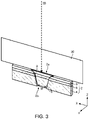
- FIG. 3 to FIG. 5 are diagrams for explaining the primary milling.
- FIG. 3 is a schematic perspective view of the specimen 2 and the shielding member 30.
- FIG. 4 is a diagram for explaining the oscillating operation of the specimen 2.
- FIG. 5 is a diagram for explaining the operation by the ion source 10.
- the specimen 2 includes a substrate 4, a multi-layered film 6 and a protective member 8.
- the substrate 4 is a semiconductor substrate, such as a silicon substrate and a compound substrate.
- the multi-layered film 6 includes wiring, transistors and the like formed on the substrate 4 by a semiconductor fabrication technique, for example.
- a specimen for a transmission electron microscope, to observe the cross-section of the multi-layered film 6 formed on the substrate 4, can be prepared.
- the protective member 8 is a member for protecting the multi-layered film 6 during machining, and is a glass substrate, for example.
- the protective member 8 adheres to the multi-layered film 6 using epoxy resin or the like.
- the thickness of the protective member 8 is about 100 ⁇ m, for example.
- the specimen 2 is machined to be plate-shaped in advance, of which height (dimension in the Z direction) is 500 ⁇ m to 800 ⁇ m, and width (dimension in the Y direction) is about 100 ⁇ m.
- the configuration of the specimen 2 is not limited to the example in FIG. 3 , and specimens having various configurations can be machined using the two-stage milling method, so as to be observable by the transmission electron microscope.
- the specimen 2 is positioned such that a first edge 2a of the specimen 2 is at the top, and a second edge 2b of the specimen 2 is at the bottom.
- the first edge 2a of the specimen 2 is an edge of the specimen 2 on the protective member 8 side
- the second edge 2b of the specimen 2 is an edge of the specimen 2 on the substrate 4 side.
- the specimen 2 is disposed under the shielding member 30, and the ion beam IB irradiates the specimen 2 from the first edge 2a side.
- the ion beam IB irradiates the specimen 2 via the shielding member 30.
- a swing mechanism 22 of the specimen stage 20 is operated, as illustrated in FIG. 4 , so as to oscillate the specimen 2 and the shielding member 30 with an axis A as the rotation axis.
- the swing mechanism 22 tilts (rotates) the specimen 2 and the shielding member 30 backward and forward with the axis A as the tilt axis (rotation axis).
- the axis A is an axis that is parallel with the Y axis, for example.
- the axis A is located at the boundary between the specimen 2 and the shielding member 30, for example.
- FIG. 4 illustrates the states when the tilt angle ⁇ 1 of the specimen 2 is 0°, when the tilt angle ⁇ 1 of the specimen 2 is -30°, and when the tilt angle ⁇ 1 of the specimen 2 is +30°.
- the ion source 10 is also oscillated when the specimen 2 is machined.
- the ion source 10 is tilted from the Z axis within a predetermined angle range.
- the ion beam IB can irradiate the machining surface of the specimen 2 from the diagonal direction.
- the ion source 10 is tilted so that the incident angle of the ion beam IB becomes about 0.4° with respect to the machining surface of the specimen 2.
- the range of the tilt angle ⁇ 2 of the ion source 10 is from -0.4° to +0.4°.
- the tilt angle ⁇ 2 of the ion source 10 may be changed in accordance with the material or the like of the specimen 2.
- the ion beam IB irradiates the specimen 2 and the specimen 2 is machined, while oscillating the specimen 2 and also oscillating the ion source 10.
- two tilt surface 3 and a machining region 5, which is between the two tilt surface 3, are formed by the machining.
- the entire machining region 5 is machined as to have thickness that is approximately the same as the thickness of the shielding member 30.
- machining ends when the second edge 2b of the specimen 2 reaches a thickness suitable for the secondary milling.
- the specimen 2 is disposed such that the second edge 2b is at the top and the first edge 2a is at the bottom, and the ion beam IB irradiates the specimen 2 from the second edge 2b side. Therefore if the thickness of the specimen 2 on the second edge 2b side is large, the amount of the ion beam IB irradiating the second edge 2b side increases, and the second edge 2b side can be rapidly milled. Because of this, the specimen 2 may be milled out before the multi-layered film 6 is thinned. Therefore in the primary milling, the second edge 2b of the specimen 2 may be controlled to have a thickness suitable for the secondary milling.
- the thickness of the second edge 2b of the specimen 2 here cannot be checked in the image photographed by the camera 60.
- the machining width W illustrated in FIG. 3 the timing to end the machining of the primary milling is determined.
- the machining region 5 of the specimen 2 becomes thinner and the machining width W increases as machining progresses. Therefore the thickness of the machining region 5 can be estimated based on the machining width W.
- the thickness of the second edge 2b of the specimen 2 can be controlled to about 10 ⁇ m, which is the thickness suitable for the secondary milling.
- the information processing device 70 controls the illumination system 40, and acquires a machining control image used for controlling machining and a display image which is displayed on the display unit 76.
- a machining control image used for controlling machining and a display image which is displayed on the display unit 76.
- an image of the specimen 2 illuminated by the transmission illumination and the coaxial illumination is photographed by the camera 60, so as to acquire the machining control image.
- an image of the specimen 2 illuminated by the coaxial illumination is photographed by the camera 60, so as to acquire the display image.
- the illumination conditions under which the display image is photographed may be changed in accordance with the instruction by the user.
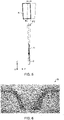
- FIG. 6 illustrates an example of the machining control image I2 photographed by the camera 60.
- the machining control image I2 in FIG. 6 is an image acquired by photographing the specimen 2 illuminated by the coaxial illumination and the transmission illumination with the camera 60.
- the machining region 5 of the specimen 2, the non-machining region of the specimen 2, and the shielding member 30 become bright, but the tilt surface 3 becomes dark in the machining control image 12, as illustrated in FIG. 6 .
- the illumination light is reflected toward the camera 60 only on the surface vertical to the observation direction (optical axis of the camera 60).
- the tilt surface 3 is not a surface vertical to the observation direction, hence the illumination light reflected by the tilt surface 3 is not directed toward the camera 60. Therefore in the machining control image 12, the tilt surface 3 becomes dark.
- the orientation of the surface of each region of the specimen 2 does not change, even if the specimen 2 is oscillated. This means that in the coaxial illumination, an image in which the tilt surface 3 is dark is always acquired, even if the specimen 2 is oscillated during machining.
- the specimen 2 is also illuminated by the transmission illumination, hence the illumination light leaks through the gap between the specimen 2 and the shielding member 30. Moreover, the illumination light strays into the space under the specimen 2. Therefore in the machining control image 12, the gap between the specimen 2 and the shielding member 30 and the space under the specimen 2 becomes bright. As a result, in the machining control image 12, only the tilt surface 3 becomes dark.
- two tilt surfaces 3 are extracted from the machining control image 12, utilizing that only the two tilt surfaces 3 become dark, and measures the machining width W by measuring the distance between the extracted two tilt surfaces 3. Then the end of machining is determined by determining whether this machining width W reached a target machining width.
- FIG. 7 is a diagram for explaining the secondary milling.
- the specimen 2 is positioned such that the second edge 2b of the specimen 2 is at the top and the first edge 2a of the specimen 2 is at the bottom. Further, in the secondary milling, the ion beam IB irradiates the specimen 2 from the second edge 2b side. In the secondary milling, the ion beam IB irradiates the specimen 2 directly, without using the shielding member 30.
- the specimen 2 is machined until the multi-layered film 6 of the specimen 2 is thinned to be observable by the transmission electron microscope.
- the information processing device 70 controls the illumination system 40, and acquires a machining control image used for controlling machining and a display image which is displayed on the display unit 76.
- the machining control image is acquired by photographing the specimen 2 illuminated by the transmission illumination with the camera 60.
- an image of the specimen 2 illuminated by the transmission illumination and the coaxial illumination is photographed by the camera 60, so as to acquire the display image.
- the illumination conditions under which the display image is photographed may be changed in accordance with the instruction by the user.
- FIG. 8 illustrates an example of the machining control image I4 photographed by the camera 60.
- the machining control image I4 in FIG. 8 is an image acquired photographing the specimen 2 illuminated by the transmission illumination with the camera 60.
- the information processing device 70 detects the lower end edge of the machining region 5, and determines the end of the machining by detecting whether the lower end edge reached the target machining position.
- FIG. 9 and FIG. 10 are diagrams for explaining the bulk machining method.
- FIG. 9 is a schematic perspective view of the specimen 2 and the shielding member 30.
- FIG. 10 is a diagram for explaining the oscillating operation of the specimen 2.
- the shielding member 30 is disposed on the specimen 2, as illustrated in FIG. 9 , and the ion beam IB is emitted from the ion source 10 disposed above the shielding member 30.
- the ion beam IB irradiates the specimen 2 via the shielding member 30.
- the swing mechanism 22 of the specimen stage 20 is operated, as illustrated in FIG. 10 , so as to oscillate the specimen 2 and the shielding member 30 with the axis A as the rotation axis.
- the swing mechanism 22 tilts and moves the specimen 2 and the shielding member 30 backward and forward with the axis A as the tilt axis.
- FIG. 10 illustrates the states when the tilt angle ⁇ 1 of the specimen 2 is 0°, when the tilt angle ⁇ 1 of the specimen 2 is -30°, and when the tilt angle ⁇ 1 of the specimen 2 is +30°.
- the ion source 10 is also oscillated when the specimen 2 is machined.
- the ion source 10 is tilted from the Z axis within a predetermined angle range.
- the ion beam IB can irradiate the machining surface of the specimen 2 from the diagonal direction.
- the ion source 10 is tilted so that the incident angle of the ion beam IB becomes about 2.5° with respect to the machining surface of the specimen 2.
- the range of the tilt angle ⁇ 2 of the ion source 10 is from -2.5° to +2.5°.
- the information processing device 70 controls the illumination system 40, and acquires a machining control image used for controlling the machining and a display image which is displayed on the display unit 76.
- a machining control image used for controlling the machining and a display image which is displayed on the display unit 76.
- an image of the specimen 2 illuminated by the transmission illumination is photographed by the camera 60, so as to acquire the machining control image.
- an image of the specimen 2 illuminated by the transmission illumination and the coaxial illumination is photographed by the camera 60, so as to acquire the display image.
- the illumination conditions under which the display image is photographed may be changed in accordance with the instruction by the user.
- FIG. 11 illustrates an example of the machining control image I6 photographed by the camera 60.
- the transmission illumination is performed on the specimen 2, the illumination light emitted from the transmission illumination device 42. Therefore in the machining control image 16, light that leaks through the gap between the specimen 2 and the shielding member 30 can be observed. Further, in the machining control image 16, the light that strays into the space under the specimen 2 can be observed.
- the information processing device 70 brightness of the light transmitted through the specimen 2 is detected out of the region enclosed by the double circles of the cursor, and the end of machining is determined based on the detected brightness.
- the information processing device 70 performs the primary milling processing to machine the specimen 2 by the primary milling.
- FIG. 12 is a flow chart illustrating an example of the primary milling processing.
- First the image acquiring unit 720 controls the illumination system 40 so that the specimen 2 is illuminated under the display illumination conditions (S100). Thereby the specimen 2 is illuminated under the display illumination conditions.
- the illumination system 40 is controlled so that the specimen 2 is illuminated by the coaxial illumination.
- the specimen 2 is illuminated by the transmission illumination device 42 and the coaxial illumination device 44.
- the illumination conditions when the display image is photographed may be set in advance, or may be set by the user using the operation unit 74.
- the image acquiring unit 720 controls the camera 60 and photographs the specimen 2 illuminated under the display illumination conditions (S 102).
- the image of the specimen 2 photographed by the camera 60 is sent to the information processing device 70.
- the image acquiring unit 720 acquires the image sent from the camera 60, and generates the display image by magnifying or demagnifying the image so that the predetermined observation magnification is implemented.
- the display control unit 724 displays this display image on the display unit 76 (S 104). Thereby the image of the specimen 2 is displayed on the display unit 76.
- the machining control unit 722 starts processing to emit the ion beam IB (S 106). Specifically, the machining control unit 722 generates a control signal to emit the ion beam IB, and sends the control signal to the control circuit 12. The control circuit 12 generates a drive signal based on the control signal, and outputs the drive signal to the ion source 10. Thereby the ion beam IB is emitted from the ion source 10 onto the specimen 2. At this time, the machining control unit 722 operates the swing mechanism 22 of the specimen stage 20, and oscillates the specimen 2 and the shielding member 30.
- the ion beam IB irradiates the specimen 2 via the shielding member 30 to machine the specimen 2, while oscillating the specimen 2 and the shielding member 30, and also oscillating the ion source 10.
- the machining control unit 722 determines whether the swing mechanism 22 completed one cycle of operation (S108). As illustrated in FIG. 4 , a one cycle operation of the swing mechanism 22 is from the state when the tilt angle ⁇ 1 of the specimen 2 is 0° (initial position) to the state when the tilt angle ⁇ 1 of the specimen 2 is -30°, to the state where the tilt angle ⁇ 1 is +30°, and then back to the state where the tilt angle ⁇ 1 is 0° again.
- the machining control unit 722 determines that the swing mechanism 22 completed one cycle of operation (Yes in S108)
- the machining control unit 722 stops emission of the ion beam IB, the oscillation operation of the specimen 2 caused by the swing mechanism 22, and the oscillation operation of the ion source 10 (S110).
- the image acquiring unit 720 controls the illumination system 40 so that the specimen 2 is illuminated under the display illumination conditions (S112).
- the image acquiring unit 720 controls the camera 60 and photographs the specimen 2 illuminated under the display illumination conditions (S114), and the display control unit 724 displays the display image on the display unit 76 (S116). Thereby the image of the specimen 2 that is currently being machined is displayed on the display unit 76.
- the image acquiring unit 720 controls the illumination system 40 so that the specimen 2 is illuminated under the machining control illumination conditions (S118).
- the illumination system 40 is controlled so that the specimen 2 is illuminated by the transmission illumination and the coaxial illumination.
- the transmission illumination is performed on the specimen 2 using the transmission illumination device 42
- the coaxial illumination is performed on the specimen 2 using the coaxial illumination device 44.
- the image acquiring unit 720 controls the camera 60 and photographs the specimen 2 illuminated under the machining control illumination conditions (S120).
- the image of the specimen 2 photographed by the camera 60 is sent to the information processing device 70.
- the image acquiring unit 720 receives the image from the camera 60, segments a predetermined region of this image, and performs image processing (e.g. change in magnification) on this region, so as to generate the machining control image. Based on this machining control image, the machining control unit 722 determines whether or not the machining is ended (S122).
- image processing e.g. change in magnification
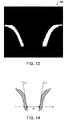
- FIG. 13 and FIG. 14 are diagrams for explaining the processing to determine whether the machining is ended.
- the machining control unit 722 binarizes the machining control image and generates a binary image I2B. Thereby the tilt surfaces 3 can be extracted. Then in this binary image I2B, the machining control unit 722 specifies aggregates of white pixels which correspond to the tilt surface 3, and measures the machining width W by measuring the distance between the two aggregates. To measure the machining width W, the edges of the two aggregates are linearly approximated respectively, whereby an approximated line L1 and an approximated line L2 are drawn, as illustrated in FIG. 14 . Then at the position P to measure the machining width W, the distance between the approximated line L1 and the approximated line L2 is determined. Thereby the machining width W can be measured. The position P at which the machining width W is measured is set in advance, and is specified by the positional coordinates of the binary image I2B in the vertical direction, for example.
- the machining control unit 722 determines whether the machining width W reached a target machining width TW or more. In other words, the machining control unit 722 determines whether W ⁇ TW is satisfied. If W ⁇ TW is satisfied, the machining control unit 722 determines that the machining is ended.
- the processing unit 72 returns to processing S106, and performs processing steps S106, S108, S110, S112, S114, S116, S118, S120 and S122.
- the processing unit 72 repeats the processing steps S106, S108, S110, S112, S114, S116, S118, S120 and S122 until it is determined that the machining is ended.
- the image acquiring unit 720 controls the camera 60, and photographs the specimen 2 illuminated under the display illumination conditions (S126), and the display control unit 724 displays the display image on the display unit 76 (S128). Thereby the image of the specimen 2 after the machining is ended is displayed on the display unit 76.
- the processing unit 72 ends the primary milling processing.
- the information processing device 70 performs the secondary milling processing to machine the specimen 2 by the secondary milling.
- the image acquiring unit 720 controls the illumination system 40 so that the specimen 2 is illuminated under the machining control illumination conditions, the illumination system 40 is controlled so that the specimen 2 is illuminated by the transmission illumination and the coaxial illumination.
- the image acquiring unit 720 controls the illumination system 40 in the processing S118 so that the specimen 2 is illuminated by the transmission illumination, which is different from the primary milling processing.
- transmission illumination is performed on the specimen 2 by the transmission illumination device 42 in the processing S118.
- the illumination system 40 is controlled so that the specimen 2 is illuminated by the coaxial illumination in the processing steps S100, S112 and S124 in which the illumination system 40 is controlled such that the specimen 2 is illuminated under the display illumination conditions.
- the illumination system 40 is controlled so that the specimen 2 is illuminated by the transmission illumination and the coaxial illumination.
- the processing S122 to determine whether the machining is ended is also different from the primary milling processing.
- the machining control unit 722 detects the lower end edge of the machining region 5, and determines whether the machining is ended depending on whether the position of the detected lower end edge reached the target position.
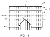
- FIG. 15 is a diagram for explaining the processing to detect the lower end edge E of the machining region 5.
- the broken line indicates a line to acquire the brightness profile for detecting the lower end edge E of the machining region 5.
- the machining control unit 722 acquires a plurality of brightness profiles in the vertical direction of the machining control image 14, and specifies the position of the lower end edge E of the machining region 5.
- the machining control unit 722 specifies an edge E0 of which distance from the target position TP is the shortest in the detection result of the edge E in the plurality of brightness profiles.
- the secondary milling processing is performed in the same manner as the above mentioned primary milling process, except that the machining control illumination conditions, the display illumination conditions and the method for determining whether the machining is ended are different.
- the information processing device 70 performs the bulk machining processing to machine the specimen 2 by the bulk machining method.
- FIG. 16 is a flow chart illustrating an example of the bulk machining processing.
- First the image acquiring unit 720 controls the illumination system 40 so that the specimen 2 is illuminated under the display illumination conditions (S200). Thereby the specimen 2 is illuminated under the display illumination conditions.
- the illumination system 40 is controlled so that the specimen 2 is illuminated by the transmission illumination and the coaxial illumination.
- the transmission illumination is performed on the specimen 2 using the transmission illumination device 42
- the epi-illumination is performed on the specimen 2 using the coaxial illumination device 44.
- the illumination conditions when the display image is photographed may be set in advance in accordance with the machining method, or may be set by the user using the operation unit 74.
- the image acquiring unit 720 controls the camera 60 and photographs the specimen 2 illuminated under the display illumination conditions (S202).
- the image acquiring unit 720 acquires the image sent from the camera 60, and generates the display image by magnifying or demagnifying the image so that the predetermined observation magnification is implemented.
- the display control unit 724 displays this display image on the display unit 76 (S204).
- the machining control unit 722 starts processing to emit the ion beam IB (S206).
- the machining control unit 722 determines whether the tilt angle ⁇ 1 of the specimen 2 is 0° (S208). If it is determined that the tilt angle ⁇ 1 is 0° (Yes in S208), the machining control unit 722 stops emission of the ion beam IB, the oscillation operation of the specimen 2 caused by the swing mechanism 22, and the oscillation operation of the ion source 10 (S210).
- the image acquiring unit 720 controls the illumination system 40 so that the specimen 2 is illuminated under the display illumination conditions (S212).
- the image acquiring unit 720 controls the camera 60 and photographs the specimen 2 illuminated under the display illumination conditions (S214), and the display control unit 724 displays the display image on the display unit 76 (S216). Thereby the image of the specimen 2 that is currently being machined is displayed on the display unit 76.
- the image acquiring unit 720 controls the illumination system 40 so that the specimen 2 is illuminated under the machining control illumination conditions (S218). If it is determined that the tilt angle ⁇ 1 is not 0° (No in S208), the image acquiring unit 720 controls the illumination system 40 in the same manner so that the specimen 2 is illuminated under the machining control illumination conditions (S218).
- the illumination system 40 is controlled so that the transmission illumination is performed on the specimen 2.
- the transmission illumination is performed on the specimen 2 using the transmission illumination device 42, and the coaxial illumination device 44 is turned OFF.
- the image acquiring unit 720 controls the camera 60 and photographs the specimen 2 illuminated under the machining control illumination conditions (S220).
- the image of the specimen 2 photographed by the camera 60 is sent to the information processing device 70.
- the image acquiring unit 720 receives the image from the camera 60, segments a predetermined region, and performs image processing (e.g. change of magnification) on this region, so as to generate the machining control image. Based on this machining control image, the machining control unit 722 determines whether the machining is ended (S222).
- image processing e.g. change of magnification
- FIG. 17 is a diagram for explaining the processing to determine whether the machining is ended.
- the machining control unit 722 masks the light which leaks through the gap between the specimen 2 and the shielding member 30, and the light which strays into the space under the specimen 2, based on the distribution of the brightness of the machining control image 16. For example, a plurality of brightness profiles of the machining control image I6 in the vertical direction are acquired, and based on these brightness profiles, the machining control unit 722 generates a mask region M1 to mask the light which leaks through the gap, and a mask region M2 to mask the light which strays into the space under the specimen 2. By generating the mask region M1 and the mask region M2, a region corresponding to the specimen 2 can be extracted from the machining control image 16.
- the region corresponding to the specimen 2 can be extracted from the machining control image 16, even in the case where the specimen 2 is tilted (in the case of tilted angle ⁇ 1 ⁇ 0°).
- the machining control unit 722 detects the maximum brightness in a non-mask region M0, which is a region of the machining control image I6 excluding the mask region M1 and the mask region M2. For example, the machining control unit 722 detects the maximum brightness in the non-mask region M0 in the region specified by the cursor C.
- the illumination light starts to transmit through the specimen 2.
- the brightness of the region corresponding to the transmitting light in the machining control image I6 increases.
- the machining control unit 722 detects this increase in brightness by detecting the maximum brightness in the non-mask region M0, whereby the end of machining is determined. For example, the machining control unit 722 determines that the machining is ended in the case where the maximum brightness reaches the threshold or more.
- the threshold may be set based on the light leaking through the gap between the specimen 2 and the shielding member 30. For example, the machining control unit 722 may determine that the machining is ended in the case where the maximum brightness reached 80% of the light leaking through the gap.
- the processing unit 72 returns to processing S206, and performs processing steps S206, S208, S210, S212, S214, S216, S218, S220 and S222.
- the processing unit 72 repeats the processing steps S206, S208, S210, S212, S214, S216, S218, S220 and S222 until the end of machining is determined.
- the image acquiring unit 720 also controls the illumination system 40 so that the specimen 2 is illuminated under the display illumination conditions (S224).
- the image acquiring unit 720 controls the camera 60 and photographs the specimen 2 illuminated under the display illumination conditions (S226), and the display control unit 724 displays the display image on the display unit 76 (S228). Thereby the image of the specimen 2 after the machining is ended is displayed on the display unit 76.
- the processing unit 72 ends the bulk machining processing.
- the display image and the control image are acquired once every cycle of the oscillating operation of the specimen 2.
- the timing of ending the machining must be determined more accurately than the primary milling and the secondary milling.
- the processing unit 72 performs: the processing to control the illumination system 40 so that the specimen 2 is illuminated under the machining control illumination conditions; the processing to acquire the machining control image by photographing the specimen 2, which is illuminated under the machining control illumination conditions, using the camera 60; the processing to control the ion source 10 based on the machining control image; the processing to control the illumination system 40 so that the specimen 2 is illuminated under the display illumination conditions, which are different from the machining control illumination conditions; the processing to acquire the display image by photographing the specimen 2, which is illuminated under the display illumination conditions, using the camera 60; and the processing to display the display image on the display unit 76.
- the machining control image and the display image can be photographed under different illumination conditions.
- an image suitable for the machining control image and an image suitable for the display image can be acquired. Therefore machining can be accurately performed by appropriately controlling the ion source using the machining control image, and the user can accurately recognize the machining state by the display image displayed on the display unit 76.
- the machining control image is preferably an image that is always photographed under the same illumination conditions, but it is preferable that the user can freely change the illumination conditions for the display image, even during the machining.
- the machining control image and the display image can be photographed under different illumination conditions, hence while the machining control image is always photographed under the same illumination conditions, the display image can be photographed under the illumination conditions freely set by the user.
- FIG. 18 is an image of the specimen 2 illuminated by the transmission illumination and the coaxial illumination, photographed by the camera 60 in the secondary milling.
- FIG. 19 is an image of the specimen 2, illuminated by the transmission installation, photographed by the camera 60 in the secondary milling.
- FIG. 20 is an image of the specimen 2, illuminated by the transmission illumination, photographed by the camera 60 in the bulk machining.
- FIG. 21 is an image of the specimen 2, illuminated by the transmission illumination and the coaxial illumination, photographed by the camera 60 in the bulk machining.
- the processing unit 72 stops the ion source 10 from emitting the ion beam IB before photographing the specimen 2 illuminated under the display illumination conditions with the camera 60. Therefore in the specimen machining device 100, it can be prevented that the specimen 2 is machined by the ion beam IB while the display image is being photographed.
- the machining control unit 722 determines the end of machining, but a mode in which the user determines the end of machining and a mode in which the machining control unit 722 determines the end of machining, for example, may be selectable.
- the user checks the machining state by observing the display image displayed on the display unit 76, and determines whether the machining is ended.
- the machining control unit 722 stops emission of the ion beam IB when the user inputs an instruction to end the machining using the operation unit 74.
- the display illumination conditions are set in advance, but the display illumination conditions may be changed based on the instruction by the user.
- the image acquiring unit 720 receives the instruction to change the display illumination conditions, changes the display illumination conditions based on this instruction, and controls the illumination system 40 so that the specimen 2 is illuminated under the updated display illumination conditions.
- the user inputs an instruction to change the display illumination conditions to the transmission illumination using the operation unit 74, then the image acquiring unit 720 controls the transmission illumination device 42 so that the transmission illumination is performed on the specimen 2. At this time, the image acquiring unit 720 turns the coaxial illumination device 44 OFF. The image acquiring unit 720 receives the instruction to change the display illumination conditions before the processing S112, illustrated in FIG. 12 , for example.
- the processing unit 72 receiving the instruction to change the display illumination conditions, changing the display illumination conditions based on this instruction, and controlling the illumination system 40 so that the specimen 2 is illuminated under the updated display illumination conditions, as described above, the user can observe the specimen 2 that is being machined under various illumination conditions.
- the image acquiring unit 720 receives the instruction to change the magnification of the display image, and changes the magnification of the display image based on this instruction to change the magnification.
- the display control unit 724 displays the display image, of which magnification is updated, on the display unit 76.
- the image acquiring unit 720 receives the instruction to change the field-of-view of the display image, and changes the field-of-view of the display image based on this instruction to change the field-of-view.
- the display control unit 724 displays the display image, of which field-of-view is updated, on the display unit 76.
- the image acquiring unit 720 receives the instruction to change the magnification and the field-of-view of the display image, and changes the magnification and the field-of-view of the display image based on this instruction to change the magnification and the field-of-view.
- the display control unit 724 displays the display image of which magnification and field-of-view are updated, on the display unit 76.
- FIG. 22 to FIG. 24 are images for explaining the processing to change the magnification and the field-of-view of the display image.
- the image 110 in FIG. 22 is an image of all the pixels of the camera 60 photographed by the camera 60
- FIG. 23 illustrates the state of segmenting an instructed region from the image 110
- the image 112 in FIG. 24 is an image generated by segmenting the instructed region from the image 110 and magnifying the segmented region.
- the camera 60 is a high pixel camera. Therefore as illustrated in FIG. 23 , the image acquiring unit 720 segments the region instructed by the user, from the image I10 in FIG. 22 , and magnifies the segmented region, whereby an image 112 is generated. Then the display control unit 724 displays the image 112 on the display unit 76 as the display image. In this way, the image acquiring unit 720 changes the magnification using digital zoom. Further, the field-of-view can be changed by changing the segmenting position in the image 110. Thus the image acquiring unit 720 changes the magnification and the field-of-view of the display image by image processing.
- the image acquiring unit 720 receives the instruction to change the brightness of the display image, and changes the brightness of the display image based on this instruction to change the brightness.
- the image acquiring unit 720 receives the instruction to change the contrast of the display image, and changes the contrast of the display image based on this instruction to change the contrast.
- the brightness or contrast of the display image is changed performing image processing on the image photographed by the camera 60.
- the magnification, the field-of-view, the brightness and the contrast of the display image can be freely changed.
- the image acquiring unit 720 may display a plurality of display images having different magnifications and fields-of-view side-by-side on the display unit 76.
- FIG. 25 illustrates processing to segment the instructed two regions from the image 110 photographed by the camera 60.
- FIG. 26 illustrates an image 114 generated by segmenting the instructed regions from the image 110 and magnifying the segmented regions.
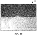
- FIG. 27 illustrates an image 116 generated by segmenting the instructed regions from the image 110 and magnifying the segmented regions.
- the image acquiring unit 720 segments the two regions specified by the user and magnifying the segmented regions, so as to generate the image 114 and the image 116.
- the display control unit 724 displays the image 114 and the image 116 side-by-side on the display unit 76.
- the display control unit 724 may display the image 114 and the image 116 alternately on the display unit 76.
- the size (area) of the image 114 segmented from the image 110 is larger than the size (area) of the image 116 segmented from the image 110.
- the size of the image 114 and the size of the image 116 are the same. This means that two images (image 114 and image 116) having different magnifications are displayed on the display unit 76.
- the image acquiring unit 720 segments a region, which the user specified from the image 110 photographed by the camera 60, and magnifies the region, so as to generate the display image.
- the image acquiring unit 720 may repeat the processing steps to acquire the machining control image and detect a region, in which change is large, from the repeatedly acquired machining control images, and magnify a region of the display image corresponding to the detected position in which change is large.
- the machining width W is measured in the processing S122 in which whether machining is ended is determined.
- the machining control unit 722 compares a machining control image acquired for the n-th time and a machining control image acquired for the (n-1)-th time, and detects a region in which change is large.
- the machining control unit 722 compares a machining control image acquired for the n-th time and a machining control image acquired for the (n-1)-th time, and detects a region in which change is large.
- the machining control image acquired for the n-th time the machining control image acquired for the (n-1)-th time
- the machining control unit 722 specifies a position (coordinates) of the detected region in which change is large, and the image acquiring unit 720 magnifies a region of the display image corresponding to the detected position of the region in which change is large.
- the display control unit 724 displays the display image, generated by magnifying the region in which change is large, on the display unit 76.
- the machining control unit 722 detects a region in which change of the machining control image is large, and the image acquiring unit 720 magnifies a region of the display image corresponding to the detected position of the region in which change is large.
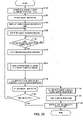
- FIG. 28 and FIG. 29 are flow charts illustrating a modification of the primary milling processing.
- the image acquiring unit 720 performs processing S300 to display on the display unit 76 a first display image and a second display image after the processing S110 to stop emission of the ion beam IB, without performing the processing steps S112, S114 and S116, which is different from the primary milling processing described above with reference to FIG. 12 .
- the image acquiring unit 720 controls the illumination system 40 first, as illustrated in FIG. 29 , so that the specimen 2 is illuminated under the first display illumination conditions (S302). Under the first display illumination conditions, the specimen 2 is illuminated by the transmission illumination, for example.
- the image acquiring unit 720 controls the camera 60 and photographs the specimen 2 illuminated under the first display illumination conditions (S304), and the display control unit 724 displays the first display image on the display unit 76 (S306).
- the image acquiring unit 720 controls the illumination system 40 so that the specimen 2 is illuminated under the second display illumination conditions (S308). Under the second display illumination conditions, the specimen 2 is illuminated by the epi-illumination, for example.
- the image acquiring unit 720 controls the camera 60 and photographs the specimen 2 illuminated under the second display illumination conditions (S310), and the display control unit 724 displays the second display image on the display unit 76 (S312).
- the processing unit 72 performing the processing S300, the first display image which was photographed in the transmission illumination; and the second display image which was photographed in the epi-illumination, are displayed on the display unit 76.
- the processing unit 72 performs: the processing to control the illumination system 40 so that the specimen 2 is illuminated under the first display illumination conditions, the processing for the camera 60 to photograph the specimen 2 illuminated under the first display illumination conditions and acquire the first display image; the processing to display the first display image on the display unit 76; the processing to control the illumination system 40 so that the specimen is illuminated under the second display illumination conditions; the processing for the camera 60 to photograph the specimen 2 illuminated under the second display illumination conditions and acquire the second display image; and the processing to display the second display image on the display unit 76.
- the two display images photographed under different illumination conditions are displayed on the display unit 76, and the user can recognize the machining state of the specimen 2 more accurately.
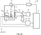
- FIG. 30 is a diagram illustrating a modification of the configuration of the specimen machining device 100.
- the specimen stage 20 includes a tilt mechanism 24 to control an incident angle of the ion beam IB with respect to the specimen 2 by tilting the specimen 2.
- FIG. 31 is a diagram for explaining the operation of the tilt mechanism 24.
- the ion source 10 is oscillated, and the ion beam IB irradiates the machining surface of the specimen 2 from the diagonal direction.
- the ion beam IB may irradiate the machining surface of the specimen 2 from the diagonal direction by oscillating the specimen 2 without oscillating the ion source 10.
- the tilt mechanism 24 tilts the specimen 2 with an axis parallel with the X axis as the tilt axis.
- the range of the tilt angle ⁇ 3 of the specimen 2 that can be tilted by the tilt mechanism 24 may be arbitrarily set in accordance with the material of the specimen 2, and the like.
- the image acquiring unit 720 acquires the display image by photographing the specimen 2, which is tilted at a first tilt angle by the tilt mechanism 24, with the camera 60, and acquires the display image by photographing the specimen 2, which is tilted at a second tilt angle that is different from the first tilt angle, with the camera 60, and the display control unit 724 displays the display image photographed at the first tilt angle and the display image photographed at the second tilt angle on the display unit 76.
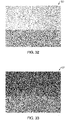
- FIG. 32 and FIG. 33 are images of the specimen 2 illuminated by the transmission illumination and the epi-illumination, photographed by the camera 60.
- the tilt angle ⁇ 3 By changing the tilt angle ⁇ 3, the tilt angle of the specimen 2, with respect to the optical axis of the coaxial illumination device 44, can be changed.
- the ratio of the epi-illumination light, that is reflected by the specimen 2 and enters the camera 60 can be changed.
- the influence of the light reflected by the specimen 2 is small and the influence of the light transmitted through the specimen 2 is large, compared with the image 120.
- the image 120 the multi-layered film 6 between the substrate 4 and the protective member 8 (glass) can be observed.
- the state of the periphery of the multi-layered film 6 that is thinned can be observed.
- FIG. 34 is a diagram illustrating the configuration of a specimen machining device 200 according to Modification 7.
- a composing element having the same function as a composing element of the above mentioned specimen machining device 100 is denoted with the same reference number, and detailed description thereof will be omitted.
- the illumination system 40 of the specimen machining device 200 includes a side illumination device 48.
- the illumination system 40 includes the transmission illumination device 42 which performs the transmissions illumination on the specimen 2, the coaxial illumination device 44 which performs the coaxial illumination on the specimen 2, and the side illumination device 48 which performs the side illumination on the specimen 2.
- the illumination system 40 includes the three illumination devices which illuminate the specimen 2 from mutually different directions.
- the side illumination device 48 emits the illumination light to perform the side illumination on the specimen 2.
- the side illumination light is emitted onto the specimen 2 diagonally from the side of the camera 60. If the specimen 2 is illuminated by the side illumination, a shadow is generated by irregularities on the surface of the specimen 2, hence the contours of the specimen 2 can be clearly recognized and a three-dimensional image can be acquired.
- various illumination conditions can be set, such as: the illumination conditions using the side illumination; the illumination conditions using the side illumination and the coaxial illumination; and the illumination conditions using the side illumination and the transmission illumination.
- the operation of the specimen machining device 200 is the same as the specimen machining device 100 described above, hence description thereof will be omitted.
- the end of machining is determined based on the machining control image, but the irradiation conditions of the ion beam IB may be changed based on the machining control image.
- the energy (acceleration voltage) of the ion beam IB may be changed based on the machining control image.
- the machining control unit 722 may determine the state of machining of the specimen 2 based on the machining control image, and decrease the energy (acceleration voltage) of the ion beam IB as the machining progresses.
- the invention includes configurations that are substantially the same as the configurations described in the embodiments.
- Substantially same configurations mean configurations having the same functions or methods, for example.
- the invention also includes configurations obtained by replacing non-essential elements of the configurations described in the embodiments with other elements.
- the invention further includes configurations obtained by adding known art to the configurations described in the embodiments.
Landscapes
- Physics & Mathematics (AREA)
- Chemical & Material Sciences (AREA)
- Analytical Chemistry (AREA)
- General Physics & Mathematics (AREA)
- Optics & Photonics (AREA)
- Plasma & Fusion (AREA)
- Engineering & Computer Science (AREA)
- Health & Medical Sciences (AREA)
- Life Sciences & Earth Sciences (AREA)
- Biochemistry (AREA)
- General Health & Medical Sciences (AREA)
- Immunology (AREA)
- Pathology (AREA)
- Sampling And Sample Adjustment (AREA)
- Laser Beam Processing (AREA)
Applications Claiming Priority (1)
| Application Number | Priority Date | Filing Date | Title |
|---|---|---|---|
| JP2021117757A JP7407772B2 (ja) | 2021-07-16 | 2021-07-16 | 試料加工装置および試料加工方法 |
Publications (2)
| Publication Number | Publication Date |
|---|---|
| EP4120318A2 true EP4120318A2 (de) | 2023-01-18 |
| EP4120318A3 EP4120318A3 (de) | 2023-05-17 |
Family
ID=82594703
Family Applications (1)
| Application Number | Title | Priority Date | Filing Date |
|---|---|---|---|
| EP22184620.7A Pending EP4120318A3 (de) | 2021-07-16 | 2022-07-13 | Vorrichtung und verfahren zur ionenstrahl-probenbearbeitung |
Country Status (3)
| Country | Link |
|---|---|
| US (1) | US12429333B2 (de) |
| EP (1) | EP4120318A3 (de) |
| JP (1) | JP7407772B2 (de) |
Families Citing this family (2)
| Publication number | Priority date | Publication date | Assignee | Title |
|---|---|---|---|---|
| JP7312778B2 (ja) * | 2021-03-08 | 2023-07-21 | 日本電子株式会社 | 試料加工装置の調整方法および試料加工装置 |
| KR102837161B1 (ko) * | 2023-08-16 | 2025-07-23 | 한국원자력연구원 | 시편 제작 방법, 시편, 및 시편 시험방법 |
Citations (1)
| Publication number | Priority date | Publication date | Assignee | Title |
|---|---|---|---|---|
| JP2012193962A (ja) | 2011-03-15 | 2012-10-11 | Jeol Ltd | 薄膜試料作製方法 |
Family Cites Families (9)
| Publication number | Priority date | Publication date | Assignee | Title |
|---|---|---|---|---|
| JP3117079B2 (ja) * | 1998-06-29 | 2000-12-11 | 日本電気株式会社 | イオンミリング装置およびイオンミリングの終点検出方法 |
| US7897918B2 (en) * | 2004-11-15 | 2011-03-01 | DCG Systems | System and method for focused ion beam data analysis |
| JP4594156B2 (ja) * | 2005-04-21 | 2010-12-08 | 日本電子株式会社 | 試料作製方法および試料作製装置 |
| JP4871788B2 (ja) * | 2007-05-18 | 2012-02-08 | 株式会社日立ハイテクノロジーズ | 微細試料の加工方法,観察方法及び装置 |
| JP5020908B2 (ja) * | 2008-08-29 | 2012-09-05 | 日本電子株式会社 | イオンビーム加工装置 |
| JP2011054497A (ja) * | 2009-09-03 | 2011-03-17 | Sii Nanotechnology Inc | 断面加工観察方法および装置 |
| JP5739119B2 (ja) * | 2009-09-15 | 2015-06-24 | 株式会社日立ハイテクサイエンス | 断面加工観察装置 |
| JP5517790B2 (ja) * | 2010-07-02 | 2014-06-11 | 株式会社キーエンス | 拡大観察装置 |
| US10110854B2 (en) * | 2012-07-27 | 2018-10-23 | Gatan, Inc. | Ion beam sample preparation apparatus and methods |
-
2021
- 2021-07-16 JP JP2021117757A patent/JP7407772B2/ja active Active
-
2022
- 2022-07-13 EP EP22184620.7A patent/EP4120318A3/de active Pending
- 2022-07-15 US US17/865,850 patent/US12429333B2/en active Active
Patent Citations (1)
| Publication number | Priority date | Publication date | Assignee | Title |
|---|---|---|---|---|
| JP2012193962A (ja) | 2011-03-15 | 2012-10-11 | Jeol Ltd | 薄膜試料作製方法 |
Also Published As
| Publication number | Publication date |
|---|---|
| EP4120318A3 (de) | 2023-05-17 |
| JP2023013518A (ja) | 2023-01-26 |
| US20230015109A1 (en) | 2023-01-19 |
| US12429333B2 (en) | 2025-09-30 |
| JP7407772B2 (ja) | 2024-01-04 |
Similar Documents
| Publication | Publication Date | Title |
|---|---|---|
| US6621082B2 (en) | Automatic focusing system for scanning electron microscope equipped with laser defect detection function | |
| US7532328B2 (en) | Circuit-pattern inspection apparatus | |
| US12429333B2 (en) | Specimen machining device and specimen machining method | |
| JPH02123749A (ja) | 断面加工観察装置 | |
| JPH09320505A (ja) | 電子線式検査方法及びその装置並びに半導体の製造方法及びその製造ライン | |
| KR102590634B1 (ko) | 하전 입자 빔 장치, 시료 가공 방법 | |
| US20170092460A1 (en) | Sample positioning method and charged particle beam apparatus | |
| US11837437B2 (en) | Specimen machining device and information provision method | |
| US5220169A (en) | Surface analyzing method and apparatus | |
| JP2000161948A (ja) | 回路パターン検査装置、および回路パターン検査方法 | |
| JP3836735B2 (ja) | 回路パターンの検査装置 | |
| US12476071B2 (en) | Specimen machining device and specimen machining method | |
| JP6764953B2 (ja) | 荷電粒子線装置 | |
| JPS6313342A (ja) | 微細異物検査装置 | |
| JP7593885B2 (ja) | 試料加工装置および試料加工方法 | |
| KR20220114258A (ko) | 결함 검출 방법, 이를 이용한 반도체 장치의 제조 방법 및 이를 수행하기 위한 결함 검출 시스템 | |
| JP7562480B2 (ja) | 試料加工装置および試料加工方法 | |
| JP7816444B2 (ja) | X線検査装置及びx線検査方法 | |
| JPH11274256A (ja) | 試料検査装置 | |
| JP2022186453A (ja) | 試料加工装置および試料加工方法 | |
| KR20030075925A (ko) | 주사전자현미경을 이용한 반도체소자의 분석방법 | |
| KR20220154000A (ko) | 위치 선택형 가변 광원 제어 시스템 및 방법 | |
| JPH0412254A (ja) | 内部欠陥検査方法および装置 | |
| JP2000292360A (ja) | 異物検査方法 |
Legal Events
| Date | Code | Title | Description |
|---|---|---|---|
| PUAI | Public reference made under article 153(3) epc to a published international application that has entered the european phase |
Free format text: ORIGINAL CODE: 0009012 |
|
| STAA | Information on the status of an ep patent application or granted ep patent |
Free format text: STATUS: THE APPLICATION HAS BEEN PUBLISHED |
|
| AK | Designated contracting states |
Kind code of ref document: A2 Designated state(s): AL AT BE BG CH CY CZ DE DK EE ES FI FR GB GR HR HU IE IS IT LI LT LU LV MC MK MT NL NO PL PT RO RS SE SI SK SM TR |
|
| PUAL | Search report despatched |
Free format text: ORIGINAL CODE: 0009013 |
|
| AK | Designated contracting states |
Kind code of ref document: A3 Designated state(s): AL AT BE BG CH CY CZ DE DK EE ES FI FR GB GR HR HU IE IS IT LI LT LU LV MC MK MT NL NO PL PT RO RS SE SI SK SM TR |
|
| RIC1 | Information provided on ipc code assigned before grant |
Ipc: H01J 37/22 20060101ALI20230412BHEP Ipc: H01J 37/305 20060101ALI20230412BHEP Ipc: H01J 37/304 20060101AFI20230412BHEP |
|
| STAA | Information on the status of an ep patent application or granted ep patent |
Free format text: STATUS: REQUEST FOR EXAMINATION WAS MADE |
|
| 17P | Request for examination filed |
Effective date: 20230705 |
|
| RBV | Designated contracting states (corrected) |
Designated state(s): AL AT BE BG CH CY CZ DE DK EE ES FI FR GB GR HR HU IE IS IT LI LT LU LV MC MK MT NL NO PL PT RO RS SE SI SK SM TR |