EP4119847A1 - Combustion device comprising a control device - Google Patents
Combustion device comprising a control device Download PDFInfo
- Publication number
- EP4119847A1 EP4119847A1 EP22154894.4A EP22154894A EP4119847A1 EP 4119847 A1 EP4119847 A1 EP 4119847A1 EP 22154894 A EP22154894 A EP 22154894A EP 4119847 A1 EP4119847 A1 EP 4119847A1
- Authority
- EP
- European Patent Office
- Prior art keywords
- control
- air supply
- combustion
- test result
- drift
- Prior art date
- Legal status (The legal status is an assumption and is not a legal conclusion. Google has not performed a legal analysis and makes no representation as to the accuracy of the status listed.)
- Granted
Links
- 238000002485 combustion reaction Methods 0.000 title claims abstract description 211
- 238000012360 testing method Methods 0.000 claims abstract description 417
- 230000001105 regulatory effect Effects 0.000 claims abstract description 109
- 230000006870 function Effects 0.000 claims abstract description 52
- 230000001276 controlling effect Effects 0.000 claims abstract description 5
- 230000033228 biological regulation Effects 0.000 claims description 71
- 230000000694 effects Effects 0.000 abstract description 2
- 239000000446 fuel Substances 0.000 description 38
- 230000032683 aging Effects 0.000 description 14
- 238000012545 processing Methods 0.000 description 13
- 239000007789 gas Substances 0.000 description 12
- 230000003287 optical effect Effects 0.000 description 9
- 230000007423 decrease Effects 0.000 description 8
- 238000012937 correction Methods 0.000 description 7
- 239000002737 fuel gas Substances 0.000 description 7
- 238000011088 calibration curve Methods 0.000 description 6
- 238000004880 explosion Methods 0.000 description 6
- 238000001914 filtration Methods 0.000 description 6
- 238000002955 isolation Methods 0.000 description 6
- 239000013307 optical fiber Substances 0.000 description 6
- 238000006243 chemical reaction Methods 0.000 description 5
- XLYOFNOQVPJJNP-UHFFFAOYSA-N water Substances O XLYOFNOQVPJJNP-UHFFFAOYSA-N 0.000 description 5
- 238000004891 communication Methods 0.000 description 4
- 238000005259 measurement Methods 0.000 description 4
- ATUOYWHBWRKTHZ-UHFFFAOYSA-N Propane Chemical compound CCC ATUOYWHBWRKTHZ-UHFFFAOYSA-N 0.000 description 2
- 239000000567 combustion gas Substances 0.000 description 2
- 230000000295 complement effect Effects 0.000 description 2
- 238000010438 heat treatment Methods 0.000 description 2
- 238000004519 manufacturing process Methods 0.000 description 2
- VNWKTOKETHGBQD-UHFFFAOYSA-N methane Chemical compound C VNWKTOKETHGBQD-UHFFFAOYSA-N 0.000 description 2
- 239000000203 mixture Substances 0.000 description 2
- 239000002245 particle Substances 0.000 description 2
- 239000004065 semiconductor Substances 0.000 description 2
- OQCFWECOQNPQCG-UHFFFAOYSA-N 1,3,4,8-tetrahydropyrimido[4,5-c]oxazin-7-one Chemical compound C1CONC2=C1C=NC(=O)N2 OQCFWECOQNPQCG-UHFFFAOYSA-N 0.000 description 1
- 238000012935 Averaging Methods 0.000 description 1
- UFHFLCQGNIYNRP-UHFFFAOYSA-N Hydrogen Chemical compound [H][H] UFHFLCQGNIYNRP-UHFFFAOYSA-N 0.000 description 1
- WHXSMMKQMYFTQS-UHFFFAOYSA-N Lithium Chemical compound [Li] WHXSMMKQMYFTQS-UHFFFAOYSA-N 0.000 description 1
- 230000015572 biosynthetic process Effects 0.000 description 1
- 238000004364 calculation method Methods 0.000 description 1
- 239000003795 chemical substances by application Substances 0.000 description 1
- 238000004590 computer program Methods 0.000 description 1
- 230000001419 dependent effect Effects 0.000 description 1
- 239000003651 drinking water Substances 0.000 description 1
- 235000020188 drinking water Nutrition 0.000 description 1
- 239000012530 fluid Substances 0.000 description 1
- 239000001257 hydrogen Substances 0.000 description 1
- 229910052739 hydrogen Inorganic materials 0.000 description 1
- 238000009434 installation Methods 0.000 description 1
- 229910000953 kanthal Inorganic materials 0.000 description 1
- 229910052744 lithium Inorganic materials 0.000 description 1
- XGZVUEUWXADBQD-UHFFFAOYSA-L lithium carbonate Chemical compound [Li+].[Li+].[O-]C([O-])=O XGZVUEUWXADBQD-UHFFFAOYSA-L 0.000 description 1
- 229910052808 lithium carbonate Inorganic materials 0.000 description 1
- 239000000463 material Substances 0.000 description 1
- 238000000034 method Methods 0.000 description 1
- 238000010248 power generation Methods 0.000 description 1
- 239000001294 propane Substances 0.000 description 1
- 238000010998 test method Methods 0.000 description 1
Images


Classifications
-
- F—MECHANICAL ENGINEERING; LIGHTING; HEATING; WEAPONS; BLASTING
- F23—COMBUSTION APPARATUS; COMBUSTION PROCESSES
- F23N—REGULATING OR CONTROLLING COMBUSTION
- F23N5/00—Systems for controlling combustion
- F23N5/26—Details
- F23N5/265—Details using electronic means
-
- F—MECHANICAL ENGINEERING; LIGHTING; HEATING; WEAPONS; BLASTING
- F23—COMBUSTION APPARATUS; COMBUSTION PROCESSES
- F23N—REGULATING OR CONTROLLING COMBUSTION
- F23N3/00—Regulating air supply or draught
- F23N3/002—Regulating air supply or draught using electronic means
-
- F—MECHANICAL ENGINEERING; LIGHTING; HEATING; WEAPONS; BLASTING
- F23—COMBUSTION APPARATUS; COMBUSTION PROCESSES
- F23N—REGULATING OR CONTROLLING COMBUSTION
- F23N5/00—Systems for controlling combustion
- F23N5/02—Systems for controlling combustion using devices responsive to thermal changes or to thermal expansion of a medium
- F23N5/12—Systems for controlling combustion using devices responsive to thermal changes or to thermal expansion of a medium using ionisation-sensitive elements, i.e. flame rods
- F23N5/123—Systems for controlling combustion using devices responsive to thermal changes or to thermal expansion of a medium using ionisation-sensitive elements, i.e. flame rods using electronic means
-
- F—MECHANICAL ENGINEERING; LIGHTING; HEATING; WEAPONS; BLASTING
- F23—COMBUSTION APPARATUS; COMBUSTION PROCESSES
- F23N—REGULATING OR CONTROLLING COMBUSTION
- F23N2223/00—Signal processing; Details thereof
- F23N2223/04—Memory
-
- F—MECHANICAL ENGINEERING; LIGHTING; HEATING; WEAPONS; BLASTING
- F23—COMBUSTION APPARATUS; COMBUSTION PROCESSES
- F23N—REGULATING OR CONTROLLING COMBUSTION
- F23N2223/00—Signal processing; Details thereof
- F23N2223/48—Learning / Adaptive control
-
- F—MECHANICAL ENGINEERING; LIGHTING; HEATING; WEAPONS; BLASTING
- F23—COMBUSTION APPARATUS; COMBUSTION PROCESSES
- F23N—REGULATING OR CONTROLLING COMBUSTION
- F23N2227/00—Ignition or checking
- F23N2227/20—Calibrating devices
-
- F—MECHANICAL ENGINEERING; LIGHTING; HEATING; WEAPONS; BLASTING
- F23—COMBUSTION APPARATUS; COMBUSTION PROCESSES
- F23N—REGULATING OR CONTROLLING COMBUSTION
- F23N2229/00—Flame sensors
- F23N2229/12—Flame sensors with flame rectification current detecting means
-
- F—MECHANICAL ENGINEERING; LIGHTING; HEATING; WEAPONS; BLASTING
- F23—COMBUSTION APPARATUS; COMBUSTION PROCESSES
- F23N—REGULATING OR CONTROLLING COMBUSTION
- F23N2231/00—Fail safe
- F23N2231/10—Fail safe for component failures
Definitions
- the present disclosure relates to control curves used in connection with combustion sensors in combustion devices, such as gas burners.
- Combustion sensors in combustion devices are, for example, ionization electrodes.
- the present disclosure relates to the correction of such control curves taking into account the aging and/or drift of a sensor signal.
- the air ratio ⁇ can be determined during combustion using a combustion sensor.
- the air ratio ⁇ can be determined using an ionization current through an ionization electrode.
- An alternating voltage is initially applied to the combustion sensor, in particular to the ionization electrode. Due to the rectifying effect of a flame, an ionization current flows as a direct current in only one direction.
- the ionization current detected at the combustion sensor is plotted against the speed of the fan of a combustion device.
- the ionization current is typically measured in microamperes.
- the speed of an incinerator fan is typically measured in revolutions per minute.
- the speed of the fan of a combustion device is at the same time a measure of the air supply and of the output of the combustion device, ie for a quantity of heat per unit of time.
- target values are plotted along such a control curve.
- target values can be recorded under laboratory conditions as part of tests and/or settings on a sample device.
- the recorded values are stored and taken into account in a control and/or regulation, in particular in an electronic control and/or regulation.
- Combustion sensors in particular ionization electrodes, are subject to aging during operation.
- This aging is caused by deposits and/or deposits during the operation of a combustion device.
- an oxide layer can form on the surface of an ionization electrode, the thickness of which changes over the course of the operating hours.
- the ionization current drifts as a result of aging. Consequently, a control curve recorded under laboratory conditions requires a correction from time to time, at the latest after one to three thousand hours of operation.
- a control device with correction of the control curve of an ionization electrode is disclosed in the European patent EP2466204B1 .
- the European patent EP2466204B1 is granted on November 13, 2013 to SIEMENS AG .
- a corresponding registration EP2466204A1 was published on December 16, 2010 submitted and published on June 20, 2012.
- the control curve is corrected with the aid of a test procedure in three steps, which is referred to below as the drift test.
- the control device carries out a control operation at a defined air supply or speed or output.
- the control device controls or regulates the actuators of the combustion device towards a changed feed ratio. In particular, the rotational speed of the fan of a combustion device is changed.
- the control device sets an air supply to the combustion device.
- the changed feed ratio is above the stoichiometric value of the air ratio ⁇ of 1.
- the air ratio ⁇ is preferably reduced by 0.1 or by 0.06 to values greater than or equal to 1.05.
- a target value is recalculated from the ionization current recorded and from stored data.
- EP3045816B1 Device for controlling a burner system
- a corresponding registration EP3045816A1 was published on July 20, 2016 released.
- EP3045816B1 discloses and claims a control which calculates a shifted ionization current for a different speed on the basis of a current ionization current and on the basis of a previously recorded ionization current. Then the shifted ionization current can be filtered to the historical ionization current of the other speed.
- the correction of the control curve assumes that the heat generated during the drift test can also be dissipated to consumers such as heating or service water. Otherwise, the amount of heat generated during the drift test is higher than the amount of heat removed. As a result, the temperature in the system rises and the system temperature controller turns off the combustion device. In this case, the drift test on a specific air supply cannot be completed.
- the subject matter of the present disclosure is an improved correction of the control curve of a combustion sensor, which at least partially overcomes the aforementioned disadvantages.
- the present disclosure addresses a drift test on a combustion sensor of a combustion device.
- the combustion sensor can be or include an ionization electrode, for example.
- Combustion sensors, in particular ionization electrodes are subject to aging during operation. This aging makes it necessary to carry out drift tests.
- the drift test is used to determine how far target values and/or test results of a combustion sensor, in particular an ionization electrode, have shifted as a result of aging.
- the air supply or the fan speed or the power was set or regulated so that it fits the base at which the drift test is carried out.
- the present disclosure allows for drift testing outside of the defined support points.
- an index is used to determine whether a drift test is pending at that base.
- the index can be a number of operating hours, for example, after which a drift test is carried out and/or repeated. If this is the case, the test conditions for the current air supply or fan speed or power are obtained, for example, by a suitable interpolation between the support points. A test value is then recorded based on this current (and thus at any or almost any) air supply or fan speed or output. It is also possible to record several test values of the signal from the combustion sensor, in particular from the ionization electrode. The multiple test values can then be averaged, for example, and/or checked for plausibility.
- test result obtained in this way is then applied or converted to an adjacent supporting point of the calibration curve and/or nominal value curve and/or reference value curve.
- a new filtered drift test value is determined for the neighboring interpolation point.
- the converted test result is filtered to the previous drift test value at the neighboring support point.
- This new filtered drift test value is then stored in the memory of a control and/or regulation device.
- the new filtered drift test value can be stored in the memory of the open-loop and/or closed-loop control device as part of a calibration curve and/or desired value curve and/or reference value curve.
- the distance between the current air supply or fan speed or output from the neighboring support point is taken into account.
- the weight with which the converted test result is placed on the neighboring So the vertex applied is a function of that distance.
- the weighting preferably decreases, in particular monotonically, with increasing distance. This weighted procedure avoids excessively large changes in the values of the calibration curve and/or setpoint curve and/or reference value curve. The probability of an incorrect or implausible stored value decreases.
- a current airflow or fan speed or power can have more than one adjacent breakpoint.
- two adjacent support points can be present, with the current air supply or fan speed or power being between the two adjacent support points.
- a check is then preferably carried out individually for each adjacent support point using a respective index to determine whether a drift test is pending. In particular, it can be checked for each neighboring support point based on a respective number of operating hours whether a drift test is pending.
- each weighting is a function of the respective distance of the current air supply or fan speed or power from the base or bases.
- the weights decrease as the distance of the current air supply or fan speed or power from the base increases.
- the weights can decrease monotonically and/or decrease linearly and monotonically.
- the calibration curve and/or desired value curve and/or reference value curve is kept as up-to-date as possible by applying the newly determined test result to more than one adjacent support point.
- the newly determined test result which has been converted to the adjacent interpolation points, can be applied to more than two interpolation points of the calibration curve and/or nominal value curve and/or reference value curve by means of a weighting function.
- the weighting function is preferably standardized, for example standardized to one.
- the integral over the entire range of values of a normalized weighting function is finite. In particular, this can be equal to one over the entire value range of a normalized weighting function.
- the weighting function has its maximum at the current air supply or fan speed or power. It decreases in either direction based on current airflow or fan speed or power. Preferably, the weighting function decreases monotonically in each direction based on the current air supply or fan speed or power. Particularly preferably, the weighting function decreases monotonically and linearly in each direction, starting from the current air supply or fan speed or power. through the Choosing a suitable weighting function ensures that test results for distant reference points are not corrected excessively. This reduces the probability of an incorrect or implausible stored test result or filtered drift test value.
- the newly determined and converted test result is applied to all those support points of the calibration curve and/or desired value curve and/or reference value curve for which a drift test is pending, using the weighting function.
- FIG 1 Fig. 1 shows a combustion device 1 such as a wall mounted gas burner and/or an oil burner.
- a flame of a heat generator burns in the combustion chamber 2 of the combustion device 1 .
- the heat generator exchanges the thermal energy of the hot combustion gases into another fluid such as water.
- a hot water heating system is operated and / or heated drinking water.
- a good can be heated, for example in an industrial process, with the thermal energy of the hot fuels and/or combustion gases.
- the heat generator is part of a system with combined heat and power generation, for example a motor of such a system.
- the heat generator is a gas turbine.
- the heat generator can be used to heat water in a plant for the production of lithium and/or lithium carbonate.
- the exhaust gases 3 are discharged from the combustion chamber 2, for example via a chimney.
- the air supply 5 for the combustion process is supplied via a fan 4 driven (by a motor). Via the signal line 12, a control and/or regulating device 18 specifies the air supply V L to the blower 4 that it is to convey. The fan speed thus becomes a measure of the air supply 5.
- the fan speed is reported back to the control and/or regulation device 18 by the fan 4 .
- control and/or regulating device 18 determines the speed of fan 4 via signal line 13.
- the control and/or regulation device 18 preferably includes a microcontroller.
- the control and/or regulation device 18 ideally includes a microprocessor.
- the control and/or regulating device 18 can be a regulating device.
- the control device preferably includes a microcontroller.
- the control device ideally includes a microprocessor.
- the controller may include a proportional and integral controller.
- the control device can comprise a proportional and integral and derivative controller.
- control and/or regulation device 18 can include a field-programmable (logic) gate arrangement.
- control and/or regulation device 18 can comprise an application-specific integrated circuit.
- the signal line 12 comprises an optical waveguide.
- the signal line 13 for determining the fan speed can also include an optical waveguide.
- the signal lines 12 and 13 are designed as optical waveguides. Optical fibers provide advantages in terms of galvanic isolation and protection against explosions.
- the flap and/or valve position can be used as a measure for the air supply 5 .
- a measured value derived from the signal of a pressure sensor and/or mass flow sensor and/or volume flow sensor can be used.
- the sensor 11 is advantageously arranged in the duct 5 for the air supply.
- the sensor 11 advantageously provides a signal which is converted into a flow measurement value using a suitable signal processing unit.
- the signal from the sensor 11 is reported back using a signal line 17 .
- a signal can be reported back to the control and/or regulating device 18 using the signal line 17 , which signal is a measure of an air supply 5 .
- the signal line 17 can comprise an optical waveguide.
- Optical fibers provide advantages in terms of galvanic isolation and protection against explosions.
- a suitable signal processing device for processing the signal of the sensor 11 ideally includes at least one analog-to-digital converter.
- the signal processing device, in particular the analog/digital converter(s) is integrated in the control and/or regulation device 18.
- the measured value of a pressure sensor and/or a mass flow sensor in a side channel of the air supply 5 can also be used as a measure for the air supply V L .
- a combustion device with feed channel and side channel is for example in the European patent EP3301364B1 disclosed.
- the European patent EP3301364B1 was published on June 7, 2017 filed and granted on August 7, 2019.
- a combustion device with a supply channel and a side channel is claimed, with a mass flow sensor protruding into the supply channel.
- a pressure sensor and/or a mass flow sensor in the side channel determines a signal which corresponds to the pressure value dependent on the air supply V L and/or the air flow (particle flow and/or mass flow) in the side channel.
- the sensor advantageously provides a signal which is converted into a measured value using a suitable signal processing device.
- the signals from a number of sensors are converted into a common measured value.
- a suitable signal processing device ideally includes at least one analog-to-digital converter.
- the signal processing device, in particular the analog/digital converter or converters is integrated in the control and/or regulating device 18.
- the signal processing device, in particular the analog/digital converter or converters is integrated in the pressure sensor and/or mass flow sensor.
- the sensor signals are transmitted to the control and/or regulation device 18 via a communication interface with a specified communication bus protocol.
- the air supply V L is the value of the current air flow rate.
- the air flow rate may be measured and/or reported in cubic meters of air per hour.
- the air supply V L can be measured and/or stated in cubic meters of air per hour.
- Mass flow sensors allow measurement at high flow velocities, especially in connection with combustion devices during operation. Typical values of such flow velocities are in the ranges between 0.1 meters per second and 5 meters per second, 10 meters per second, 15 meters per second, 20 meters per second, or even 100 meters per second.
- Mass flow sensors suitable for the present disclosure are, for example, OMRON® D6F-W or type SENSOR TECHNICS® WBA sensors. The usable range of these sensors typically starts at speeds between 0.01 meters per second and 0.1 meters per second and ends at a speed such as 5 meters per second, 10 meters per second, 15 meters per second, 20 meters per second, or even 100 meters per second. In other words, it can have lower limits like 0.1 meters per second
- the fuel supply V B is set and/or regulated by the control and/or regulation device 18 with the aid of a fuel actuator and/or a valve 6 that can be adjusted (by a motor).
- the fuel 7 is a fuel gas.
- a combustor 1 can then be connected to various fuel gas sources, for example sources with a high proportion of methane and/or sources with a high proportion of propane. Provision is also made for the combustion device 1 to be connected to a source of a gas or a gas mixture, the gas or the gas mixture comprising hydrogen.
- the quantity of fuel gas is set by the control and/or regulating device 18 by means of a (motor-driven) adjustable fuel valve 6 .
- the control value, for example a pulse width modulated signal, of the gas valve is a measure of the amount of fuel gas. It is also a value for the fuel supply V B .
- a gas valve is used as the fuel actuator 6, the position of a valve can be used as a measure for the quantity of fuel gas.
- a fuel actuator 6 and/or a fuel valve are set using a stepping motor. In that case, the stepping position of the stepping motor is a measure of the amount of fuel gas.
- the fuel valve can also be integrated in a unit with at least one or more safety shut-off valves.
- a signal line 14 connects the fuel actuator 6 to the open-loop and/or closed-loop control device 18.
- the signal line 14 comprises an optical waveguide. Optical fibers provide advantages in terms of galvanic isolation and protection against explosions.
- the fuel valve 6 can be a valve that is controlled internally via a flow and/or pressure sensor 10, which valve receives a desired value and regulates the actual value of the flow and/or pressure sensor 10 to the desired value.
- the flow and/or pressure sensor 10 can be implemented as a volume flow sensor, for example as a turbine wheel meter or as a bellows meter or as a differential pressure sensor.
- the flow and/or pressure sensor 10 can also be designed as a mass flow sensor, for example as a thermal mass flow sensor.
- a signal line 16 connects the flow and/or pressure sensor 10 to the control and/or regulation device 18.
- the signal line 16 comprises an optical waveguide. Optical fibers provide advantages in terms of galvanic isolation and protection against explosions.
- the flow and/or pressure sensor 10 is arranged separately from the fuel valve 6 in the fuel supply channel 8 .
- the flow sensor 10 can be implemented as a volume flow sensor, for example as a turbine wheel meter or bellows meter or as a differential pressure sensor.
- the flow and / or pressure sensor 10 can also be used as Mass flow sensor, for example, be designed as a thermal mass flow sensor.
- a signal line 16 connects the flow and/or pressure sensor 10 to the control and/or regulation device 18.
- the signal line 16 comprises an optical waveguide. Optical fibers provide advantages in terms of galvanic isolation and protection against explosions.
- That flow and/or pressure sensor 10 generates a signal which is converted into a flow measurement value (measurement value of the particle and/or mass flow and/or volume flow) using a suitable signal processing device.
- a suitable signal processing device ideally includes at least one analog-to-digital converter.
- the signal processing device in particular the analog/digital converter or converters, is integrated in the control and/or regulation device 18.
- the signal processing device in particular the analog/digital converter or converters, is integrated in the flow - and/or pressure sensor.
- the sensor signals are transmitted to the control and/or regulation device 18 via a communication interface with a specified communication bus protocol.
- FIG 1 also shows a combustion device 1 with a combustion sensor 9 for detecting an air ratio ⁇ .
- the combustion sensor 9 can comprise an ionization electrode, for example.
- the combustion sensor 9 can also be an ionization electrode.
- KANTHAL ® eg APM ® or A-1 ® , is often used as the material for an ionization electrode. Electrodes made of Nikrothal ® are also considered by those skilled in the art.
- the combustion sensor 9 is preferably arranged in the combustion chamber 2 .
- a signal line 15 connects the combustion sensor 9 to the control and/or regulating device 18.
- the signal line 15 comprises an optical waveguide.
- Optical fibers provide advantages in terms of galvanic isolation and protection against explosions.
- the combustion sensor 9 is connected to a voltage source via an impedance.
- the impedance for connection to the voltage source can include an electrical resistance, in particular an electrical, ohmic resistance.
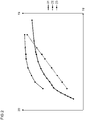
- curve 21 by way of example setpoint values for the signals from a combustion sensor 9 .
- Curve 22 shows exemplary reference values for the drift test from the signals from a combustion sensor 9 over an air supply or fan speed or output 19 .
- curves 21 and 22 can show ionization current values 20 over air supply or blower speed or output 19 .
- the air supply or fan speed or output 19 along the abscissa is preferably an air supply or fan speed or output 19 of a combustion device 1.
- the curve 21 in FIG 2 shows nominal values of the signals of a combustion sensor 9 in the as-delivered state of the at least one combustion sensor 9.
- the curve 21 shows ionization current nominal values in the as-delivered state of an ionization electrode for normal control operation.
- the curve 21 is supported by a number of values for the air supply or fan speed or output 19 .
- target values of the ionization current of an ionization electrode can be present in the delivery state.
- FIG 2 sixteen such supporting values of the air supply or fan speed or output 19 are shown as an example for curve 21 .
- a target value of a signal from a combustion sensor 9 in the delivery state belongs to each supporting value of the air supply or fan speed or output 19 .
- a target value of an ionization current of an ionization electrode in the delivery state can belong to each supporting value of the air supply or fan speed or power 19 .
- the supporting values and the associated ionization current set values form the supporting points of the control curve for normal control operation in the delivery state of the control and/or regulating device 18.
- the supporting values are such supporting values for the air supply or fan speed or output 19.
- the curve 22 in FIG 2 shows reference values for a drift test of the at least one combustion sensor 9 for changes.
- curve 22 shows reference ionization currents for a drift test of an ionization electrode for change.
- a combustion sensor 9 or an ionization electrode can change, for example due to aging.
- aging can be accompanied by the formation of deposits on the combustion sensor 9 or on the ionization electrode.
- the curve 22 is supported by a number of values for the air supply or fan speed or output 19 .
- Reference values of the signal of the at least one combustion sensor 9 exist for those values of air supply or fan speed or power 19.
- reference values of the ionization current of an ionization electrode can be present for those values of air supply or fan speed or power 19.
- FIG 2 seven such supporting values of the air supply or fan speed or output 19 are shown as an example for curve 22 .
- a reference value of a signal from a combustion sensor 9 belongs to each supporting value of the air supply or fan speed or output 19.
- each supporting value of the air supply or fan speed or output 19 can include a reference value of an ionization current for a drift test of an ionization electrode.
- the interpolation values of the air supply or fan speed or power 19 and the respective associated reference ionization currents form the interpolation points of the reference curve for drift tests of the ionization electrode.
- Support values for air supply or fan speed or power 19 for curve 22 are generally not identical to support values for air supply or fan speed or power 19 for curve 21.
- the respective support values for curves 21 and 22 can differ in number.
- the respective supporting values of the curves 21 and 22 can differ in their position. This means that the respective supporting values of the curves 21 and 22 do not belong to identical values of the air supply or fan speed or output 19.
- the curve 23 in FIG 2 represents the change in the air ratio ⁇ caused by the engine speed and/or the fuel valve during a drift test. In the present case, it represents a first, upper via a second, lower air supply or fan speed or output for a drift test of the at least one combustion sensor 9.
- the associated ordinate axis is the second ordinate axis. It covers the same range of values as the abscissa axis.
- Associated with each air supply or fan speed or power 19 breakpoint of curve 23 is an air supply or blower speed or power breakpoint 19 of curve 22.
- the air supply or fan speed or power breakpoints 19 of curve 23 correspond to the second, lower air supplies or fan speeds or powers for drift tests.
- drift test value ie a value determined from the associated test results by filtering, and an index for determining a test result are assigned to each of these drift test interpolation points.
- a reference value is assigned to each drift test node.
- the value on curve 21 corresponding to a base value of the air supply or fan speed or power 19 of curve 23 can be a base value of the air supply or fan speed or power 19 of curve 21 .
- the value on curve 21 corresponding to a base value of the air supply or fan speed or power 19 of curve 23 does not have to be a base value of the air supply or fan speed or power 19 of curve 21 .
- the values from curve 21 can be interpolated. For example, linear interpolation can be carried out between neighboring points. The interpolated value is then used to determine an associated reference value for normal control operation for a supporting value of curves 22 and 23 .
- a triangular point can be seen on each of the curves 21 to 23. These points all belong to the same air supply or blower speed or output 19. In contrast to the reference points, the point marked with a triangle corresponds to a calculated value. It can, for example, have been obtained by interpolation between the base points of each curve. A drift test can be carried out with the values obtained in this way and the test result can be evaluated or converted to the neighboring reference points.
- Intervals are formed for the decision as to whether a drift test is to be carried out on the basis of a current air supply or a current blower speed or a current output.
- the intervals are formed on the basis of the first air supply values or blower speed values or performance values of a drift test support point.
- the range of air supply or fan speed or power can be divided into intervals between the first air supply or fan speed or power of the highest and lowest drift test support point. In one embodiment, the entire range of airflow or fan speed or power is divided into intervals between the first airflow or fan speed or power of the highest and lowest drift test breakpoints.
- the intervals are selected on the basis of the first air supply values or fan speed values or performance values of the drift test support points.
- a first drift test support point P n is close to the current air supply or close to the current fan speed or close to the current power.
- a second drift test point P n+1 is further away from the current air supply or the current fan speed or the current power than the first drift test point P n .
- the second drift test node P n+1 is adjacent to the first drift test node P n .
- a first area is close to the first drift test node P n .
- Another range lies between the drift test points P n and P n+1 , but does not include the drift test points P n and P n+1 .
- Yet another area is close to the second drift test node P n+1 . Preferably, these areas do not overlap.
- each range comprises one-third of the interval between the drift test breakpoints P n and P n+1 .
- the region near P n comprises a quarter of the interval between the drift test breakpoints P n and P n+1 .
- the area near P n+1 also covers a quarter of the interval between the drift test support points P n and P n+1 .
- the range between the drift test points P n and P n+1 comprises half the interval between the drift test points P n and P n+1 .
- a drift test is performed with an air supply or fan speed or output close to Pn , the new test result from this drift test is converted to Pn .
- This conversion is analogous to that in EP3045816B1 disclosed calculation for neighboring points.
- a new ionization current from this drift test can be converted to Pn .
- the time interval until a new drift test for P n is carried out is preferably restarted. If a drift test is started in the middle area between the drift test support points P n and P n+1 , the new test result from this drift test is converted to P n and to P n+1 .
- a new ionization current from this drift test can be converted to P n and P n+1 .
- a weighting or filter value to use Following the conversion of the new test result to P n and on P n+1 the time interval or time intervals can be restarted until a new drift test is performed. Finally, if a drift test is carried out with an air supply or fan speed or output close to P n+1 , the new test result from this drift test is converted to P n+1 . In particular, a new ionization current from this drift test can be converted to Pn +1 . After the conversion to P n+1 , the time interval until a new drift test for P n+1 is carried out is preferably restarted.
- a drift test is performed when the time interval of a drift test node Pn has expired and the current air supply or fan speed or power is either in the range close to the drift test node or between drift test node Pn and Pn +1 . If there is still a time interval running at the second drift test interpolation point P n+1 before a drift test is carried out, then that time interval can be left as it is. In a specific embodiment, a conversion to the second drift test support point P n+1 can be dispensed with as long as the corresponding time interval has not yet expired. Consequently, the end of the time interval to the second drift test support point P n+1 is awaited. After that time interval has elapsed, a drift test is carried out at or near the second drift test node P n+1 .
- the test conditions for the drift test are defined using two curves.
- the reference values in particular the reference ionization currents
- the reference values can be test results determined in the laboratory and/or reference values on a reference device and/or sample device.
- the reference values can be ionization currents in drift test executions.
- the reference values, in particular the reference ionization currents can be stored, for example, as support points or using curve parameters. Turn 22 off FIG 2 shows such breakpoints for reference values.
- the curve parameters can include curve parameters of the third, fourth, fifth or higher order, for example.
- the curve parameters can include parameters of polynomials of the third, fourth, fifth or higher order.
- the change in the air ratio ⁇ during a drift test must be determined relative to each other, for example by values of the air supply or fan speed or power during the drift test.
- a curve of the first air supply or first fan speed or first power over the second air supply or second fan speed or second power can be used for this purpose.
- One such curve is curve 23 off FIG 2 in the variant supporting points and interpolation for the intermediate values.
- a curve of the ratio of the first air supply or first fan speed or first power to the second air supply or second fan speed or second power can be used for this purpose. In the simplest case it is sufficient for the ratio of the first air supply or first fan speed or first power to the second air supply or second fan speed or second power is a constant.
- a straight line is obtained as curve 23 as the curve of the first air supply or first blower speed or first power versus the second air supply or second blower speed or second power.
- curves of a higher order can also be used. It is possible that the values of the air supply or fan speed or power during the drift test are not defined in relation to each other via support points and interpolation for the intermediate values, but via a curve using polynomial coefficients. In this case, air supplies or fan speeds or outputs should also be specified, to which the measured drift of the combustion sensor 9 is converted. In particular, air supplies or blower speeds or outputs should be specified, to which the measured drift of the ionization electrode 9 is converted.
- the respective highest and lowest values of the air supply or fan speed or power must be defined, which define limits within which one or more drift tests can be carried out.
- such values are defined in a memory of a control and/or regulation device 18 .
- Those values, together with any other specified values for the air supply or fan speed or power, serve as values to which the measured drift of the combustion sensor 9 is converted. They are used as drift test breakpoints in the same manner as described above.
- conditions for the drift test are defined via curve parameters.
- conditions for the drift test can be defined using values stored in the memory of a control and/or regulating device 18 .
- P n there are few drift test support points.
- the distance of the current air supply or fan speed or power to the drift test support point P n , P n+1 can be used as a parameter.
- the converted, new test result flows into the filtered drift test value at the support point P n , P n+1 .
- the weighting of the converted, new test result is higher the closer the current air supply or fan speed or power is to the drift test support point P n , P n+1 .
- the closer the current air supply or blower speed or output is to the drift test support point P n , P n+1 the longer the time until the next drift test is due.
- a new test result is determined at a current air supply or fan speed or output 24 and converted to the drift test reference points P n , P n+1 .
- the current air supply or fan speed or power 24 is spaced two-fifths of the interval from P n to P n+1 to the first drift test node P n .
- the current air supply or blower speed or power 24 has a distance of three fifths of the interval from P n to P n+1 to the second drift test support point P n+1 .
- the second drift test node P n+1 is adjacent to the first drift test node P n .
- the new test result converted to the drift test base P n is now filtered at the previous filtered drift test value assigned to this drift test base.
- the filtering only takes place with a weighting of three-fifths compared to a test result that would have been determined exactly at the drift test node P n .
- a converted new test result can be filtered on the previous, filtered drift test value assigned to this drift test node.
- the filtering is only carried out with a weighting of three-fifths compared to a test result that would have been determined exactly at the drift test support point P n .
- the new test result converted to the second drift test node P n+1 is filtered at the previous filtered drift test value assigned to this drift test node.
- the filtering is only carried out with a weighting of two-fifths compared to a test result that would have been determined exactly at the drift test node P n+1 .
- a converted, new test result can be filtered on the previous, filtered drift test value assigned to this drift test node.
- the filtering is only carried out with a weighting of two-fifths compared to a test result that would have been determined exactly at the drift test node P n+1 .
- the weighting is not necessarily varied between zero and one hundred percent via the relative position of the current air supply or fan speed or output in the interval P n to P n+1 .
- a filter value 27 is defined for at least one drift test interpolation point P n , P n+1 .
- a filter value can be defined for each drift test support point P n , P n+1 .
- a filter value of forty percent can be defined for a drift test base.
- a filter value of forty percent can be defined in the memory of a control and/or regulating device 18 for a drift test support point.
- This filter value corresponds to the weighting factor with which a converted test result based on a test at point P n is filtered to the previous filtered drift test value assigned to the drift test interpolation point P n+1 .
- Parts of a control and/or regulation device 18 according to the present disclosure can be implemented as hardware and/or as a software module, which is executed by a computing unit, optionally with the addition of container virtualization, and/or using a cloud computer and/or using a combination of the aforementioned opportunities are realized.
- the software may include firmware and/or a hardware driver running within an operating system and/or container virtualization and/or an application program.
- the present disclosure also relates to a computer program product, which contains the features of this disclosure or carries out the necessary steps. When implemented in software, the functions described may be stored as one or more instructions on a computer-readable medium.
- RAM random access memory
- MRAM magnetic random access memory
- ROM read only memory
- EPROM electronically programmable ROM
- EEPROM electronically programmable and erasable ROM
- the at least one list of vertices is at least one list of drift test vertices.
- Each drift test base corresponds to a first over a second air supply of the combustion device (1).
- each drift test support point is assigned a drift test value and an index for determining the drift test result.
- a reference value is assigned to each drift test node.
- the first air supply of a drift test support point of the combustion device (1) is an air supply at which a drift test is started and the second air supply is an air supply at which a drift test is ended.
- the drift test serves to determine an aging-related drift of signals from the combustion sensor (9).
- the drift test is used to determine an aging-related drift of signals from an ionization electrode.
- a previous test result and an index for determining a test result are assigned to each drift test node.
- the respective drift test value includes a respective previous test result.
- the respective drift test value can be a respective previous test result.
- the respective drift test value can be an averaging or filtering over several or all previous test results that were determined or converted for this drift test reference point.
- the new test result preferably includes a new drift test result.
- the new test result is a new drift test result.
- control and/or regulation device (18) can be designed to use the at least one actuator (4) to generate a specified air supply value for the at least one combustion chamber (2) of the combustion device (1).
- control and/or regulation device (18) is designed: using the at least one actuator (4) to adjust a specified air supply to the at least one combustion chamber (2) of the combustion device (1).
- control and/or regulation device (18) is designed: to control the at least one actuator (4) to a predetermined air supply to the at least one combustion chamber (2) of the combustion device (1).
- control and/or regulation device (18) is designed: using the at least one actuator (4) to control a predetermined air supply to the at least one combustion chamber (2) of the combustion device (1).
- control and/or regulation device (18) is communicatively connected to the at least one ionization electrode (9).
- control and/or regulation device (18) is communicatively connected to the at least one ionization electrode (9).
- a reference value for the drift test can be determined from the reference values, which are assigned to the selected interpolation points, by interpolation, for example by linear interpolation.
- the test result determined is preferably evaluated against this reference value.
- a reference value for the drift test can be determined from the reference values, which are assigned to the selected interpolation points, by interpolation, for example by linear interpolation.
- a reference value for the drift test can be calculated from the reference values, which are assigned to the selected interpolation points, by interpolation, for example by linear interpolation. The test result determined is preferably evaluated against this reference value.
- a reference value for the drift test can be determined from the reference values, which are assigned to the selected interpolation points, by interpolation, for example by linear interpolation.
- the test result determined is preferably evaluated against this reference value.
- a reference value for the drift test can be determined from the reference values, which are assigned to the selected interpolation points, by interpolation, for example by linear interpolation.
- a Reference value for the drift test can be calculated. The test result determined is preferably evaluated against this reference value.
- the at least one actuator (4) preferably includes at least one fan (4).
- the at least one actuator (4) is at least one fan (4).
- the at least one list of vertices is at least one list of drift test vertices.
- Each drift test base corresponds to a first over a second air supply of the combustion device (1).
- the first air supply of a drift test support point of the combustion device (1) is an air supply at which a drift test is started and the second air supply is an air supply at which a drift test is ended.
- the drift test is used to determine an aging-related drift of signals from the combustion sensor (9).
- the drift test is used to determine an aging-related drift of signals from an ionization electrode.
- control and/or regulation device (18) is designed taking into account a difference: to calculate the respective amounts of the differences for the differences formed.
- control and/or regulation device (18) is designed taking into account a difference: to calculate differences between the predetermined air supply and the first air supply values.
- control and/or regulation device (18) can be designed taking into account a difference: to calculate amounts of the differences for the calculated differences.
- control and/or regulation device (18) is communicatively connected to the at least one ionization electrode (9).
- control and/or regulation device (18) is communicatively connected to the at least one ionization electrode (9).
- the present disclosure also teaches one of the aforementioned devices (18) including a current number of operating hours, the device (18) comprising an operating hours counter, the control and/or regulating device (18) being designed: to determine a current number of operating hours using the operating hours counter.
- the hour meter comprises a clock based on complementary metal-oxide-semiconductors.
- the operating hours counter is a clock based on complementary metal-oxide-semiconductors.
- the operating hours counter can be integrated into a programming of the device (18).
- the present disclosure also teaches one of the aforementioned devices (18), the control and/or regulation device (18) being designed: determine the changed drift test value for the selected node as a function of the new test result and as a function of the drift test value assigned to the selected node.
- the first percentage and the second percentage add up to one hundred percent.
- the first percentage and the second percentage add up to one hundred percent.
- the present disclosure also teaches one of the aforementioned devices (18), the control and/or regulation device (18) being designed: to regulate the combustion device (1) on the basis of the changed drift test value stored in the memory of the control and/or regulating device (18).
- the present disclosure also teaches one of the aforementioned devices (18), the control and/or regulation device (18) being designed: to control the combustion device (1) on the basis of the changed drift test value stored in the memory of the control and/or regulating device (18).
- the present disclosure also teaches one of the aforementioned devices (18), wherein the control and/or regulation device (18) is designed: using the changed drift test value stored in the memory of the control and/or regulating device (18) and using the at least one actuator (4) to generate an air supply to the at least one combustion chamber (2) of the combustion device (1).
- the present disclosure also teaches one of the aforementioned devices (18), wherein the control and/or regulation device (18) is designed: using the changed drift test value stored in the memory of the control and/or regulating device (18) to generate a fuel supply to the at least one combustion chamber (2) of the combustion device (1).
- the present disclosure also teaches one of the aforementioned devices (18), the control and/or regulation device (18) being designed: using the changed drift test value stored in the memory of the control and/or regulating device (18) and using the at least one actuator (4) to set an air supply to the at least one combustion chamber (2) of the combustion device (1).
- the present disclosure also teaches one of the aforementioned devices (18), the control and/or regulation device (18) being designed: setting a fuel supply to the at least one combustion chamber (2) of the combustion device (1) on the basis of the changed drift test value stored in the memory of the control and/or regulating device (18).
- the present disclosure also teaches one of the aforementioned devices (18), the control and/or regulation device (18) being designed: to control the at least one actuator (4) on the basis of the changed drift test value stored in the memory of the control and/or regulating device (18).
- the present disclosure also teaches one of the aforementioned devices (18), the control and/or regulation device (18) being designed: to control at least one fuel actuator (6) on the basis of the changed drift test value stored in the memory of the control and/or regulating device (18).
- the present disclosure also teaches one of the aforementioned devices (18), the control and/or regulation device (18) being designed: to regulate the at least one actuator (4) on the basis of the changed drift test value stored in the memory of the control and/or regulating device (18).
- the present disclosure also teaches one of the aforementioned devices (18), the control and/or regulation device (18) being designed: to regulate at least one fuel actuator (6) on the basis of the changed drift test value stored in the memory of the control and/or regulating device (18).
- control and/or regulation device (18) is designed taking into account a difference: to calculate the respective amounts of the differences for the differences formed.
- control and/or regulation device (18) is designed taking into account a difference: to calculate differences between the predetermined air supply and the first air supply values.
- control and/or regulation device (18) can be designed taking into account a difference: to calculate amounts of the differences for the calculated differences.
- the third percentage and the fourth percentage add up to one hundred percent.
- the fifth percentage and the sixth percentage add up to one hundred percent.
- the fourth percentage is equal to the seventh percentage.
- the drift test value for the first interpolation point is constantly weighted.
- the sixth percentage is equal to the seventh percentage.
- the drift test value for the second interpolation point is constantly weighted.
- the present disclosure also teaches one of the aforementioned devices (18) including a first and a second changed drift test value, the control and/or regulating device (18) being designed: to control the combustion device (1) using the first, changed drift test value stored in the memory of the control and/or regulating device (18) and using the second, changed drift test value stored in the memory of the control and/or regulating device (18).
- the present disclosure also teaches one of the aforementioned devices (18) including a first and a second changed drift test value, the control and/or regulating device (18) being designed: to control the combustion device (1) using the first, changed drift test value stored in the memory of the control and/or regulating device (18) and using the second, changed drift test value stored in the memory of the control and/or regulating device (18).
- the present disclosure also teaches one of the aforementioned devices (18) including a first and a second changed drift test value, the control and/or regulating device (18) being designed: based on the first, modified drift test value stored in the memory of the control and/or regulating device (18), and based on the second, modified drift test value stored in the memory of the control and/or regulating device (18), and based on the at least one actuator (4) to generate an air supply to the at least one combustion chamber (2) of the combustion device (1).
- the present disclosure also teaches one of the aforementioned devices (18) including a first and a second changed drift test value, the control and/or regulating device (18) being designed: a fuel supply to the at least one combustion chamber (2) based on the first, modified drift test value stored in the memory of the control and/or regulating device (18) and based on the second, modified drift test value stored in the memory of the control and/or regulating device (18) to generate the combustion device (1).
- the fuel supply to the at least one combustion chamber (2) is preferably generated using at least one fuel actuator (6).
- the present disclosure also teaches one of the aforementioned devices (18) including a first and a second modified drift test value, the control and/or regulating device (18) being designed: based on the first, modified drift test value stored in the memory of the control and/or regulating device (18), and based on the second, modified drift test value stored in the memory of the control and/or regulating device (18), and based on the at least one actuator (4) adjust an air supply to the at least one combustion chamber (2) of the combustion device (1).
- the present disclosure also teaches one of the aforementioned devices (18) including a first and a second modified drift test value, the control and/or regulating device (18) being designed: a fuel supply to the at least one combustion chamber (2) based on the first, modified drift test value stored in the memory of the control and/or regulating device (18) and based on the second, modified drift test value stored in the memory of the control and/or regulating device (18) of the combustion device (1).
- the fuel supply to the at least one combustion chamber (2) is preferably adjusted using at least one fuel actuator (6).
- the present disclosure also teaches one of the aforementioned devices (18) including a first and a second changed drift test value, the control and/or regulating device (18) being designed: to control the at least one actuator (4) based on the first, modified drift test value stored in the memory of the control and/or regulating device (18) and based on the second, modified drift test value stored in the memory of the control and/or regulating device (18). .
- the present disclosure also teaches one of the aforementioned devices (18) including a first and a second changed drift test value, the control and/or regulating device (18) being designed: to control at least one fuel actuator (6) based on the first, modified drift test value stored in the memory of the control and/or regulating device (18) and based on the second, modified drift test value stored in the memory of the control and/or regulating device (18).
- the present disclosure also teaches one of the aforementioned devices (18), including a first and a second modified drift test value, the control and/or regulating device (18) being designed: to regulate the at least one actuator (4) based on the first, modified drift test value stored in the memory of the control and/or regulating device (18) and based on the second, modified drift test value stored in the memory of the control and/or regulating device (18). .
- the present disclosure also teaches one of the aforementioned devices (18), including a first and a second modified drift test value, the control and/or regulating device (18) being designed: to regulate at least one fuel actuator (6) based on the first, modified drift test value stored in the memory of the control and/or regulating device (18) and based on the second, modified drift test value stored in the memory of the control and/or regulating device (18).
- the present disclosure further teaches a combustion device (1) comprising one of the aforementioned control and/or regulating devices (18).
Abstract
Regelung einer Verbrennungsvorrichtung. Einrichtung (18) zur Steuerung und/oder Regelung einer Verbrennungsvorrichtung (1) mit einem Feuerraum (2), mit mindestens einem Aktor (4), welcher auf eine Luftzufuhr zum Feuerraum (2) wirkt, mit mindestens einem Verbrennungssensor (9), der so angeordnet ist, dass er im Betrieb der Verbrennungsvorrichtung (1) im Bereich einer Flamme des Feuerraumes (2) liegt, wobei die Steuer- und/oder Regelungseinrichtung (18) einen Speicher mit mindestens einer Liste an Stützpunkten umfasst, wobei jeder Stützpunkt einem Luftzufuhrwert der Verbrennungsvorrichtung (1) zugeordnet ist, wobei jedem Stützpunkt ein Drifttestwert und ein Index für eine Ermittlung des Testergebnisses zugeordnet sind, wobei die Steuer- und/oder Regelungseinrichtung (18) ausgebildet ist: anhand des mindestens einen Aktors (4) eine vorgegebene Luftzufuhr zum Feuerraum (2) der Verbrennungsvorrichtung (1) zu bewirken; nach dem Bewirken der vorgegebenen Luftzufuhr, als Funktion der vorgegebenen Luftzufuhr und anhand der ersten Luftzufuhrwerte einen Stützpunkt aus der mindestens einen Liste an Stützpunkten auszuwählen.Control of a combustion device. Device (18) for controlling and/or regulating a combustion device (1) with a combustion chamber (2), with at least one actuator (4), which acts on an air supply to the combustion chamber (2), with at least one combustion sensor (9), which is arranged in such a way that when the combustion device (1) is in operation it is in the region of a flame in the combustion chamber (2), the control and/or regulating device (18) comprising a memory with at least one list of reference points, each reference point having an air supply value is assigned to the combustion device (1), with each interpolation point being assigned a drift test value and an index for determining the test result, the open-loop and/or closed-loop control device (18) being designed: based on the at least one actuator (4), a specified air supply to the to effect combustion chamber (2) of the combustion device (1); after effecting the predetermined air supply, as a function of the predetermined air supply and based on the first air supply values, select a node from the at least one list of nodes.
Description
Die vorliegende Offenbarung bezieht sich auf Regelkurven, wie sie im Zusammenhang mit Verbrennungssensoren in Verbrennungsvorrichtungen, beispielsweise in Gasbrennern, eingesetzt werden. Verbrennungssensoren in Verbrennungsvorrichtungen sind beispielsweise lonisationselektroden. Insbesondere bezieht sich die vorliegende Offenbarung auf die Korrektur solcher Regelkurven unter Berücksichtigung der Alterung und/oder Drift eines Sensorsignals.The present disclosure relates to control curves used in connection with combustion sensors in combustion devices, such as gas burners. Combustion sensors in combustion devices are, for example, ionization electrodes. In particular, the present disclosure relates to the correction of such control curves taking into account the aging and/or drift of a sensor signal.
In Verbrennungsvorrichtungen lässt sich die Luftzahl λ während der Verbrennung anhand eines Verbrennungssensors ermitteln. Insbesondere lässt sich die Luftzahl λ anhand eines lonisationsstromes durch eine lonisationselektrode ermitteln. An den Verbrennungssensor, insbesondere an die lonisationselektrode, wird dabei zunächst eine Wechselspannung angelegt. Aufgrund der Gleichrichterwirkung einer Flamme fliesst ein lonisationsstrom als Gleichstrom in nur einer Richtung.In combustion devices, the air ratio λ can be determined during combustion using a combustion sensor. In particular, the air ratio λ can be determined using an ionization current through an ionization electrode. An alternating voltage is initially applied to the combustion sensor, in particular to the ionization electrode. Due to the rectifying effect of a flame, an ionization current flows as a direct current in only one direction.
In Regelkurven für Verbrennungssensoren wird der an dem Verbrennungssensor erfasste lonisationsstrom aufgetragen über der Drehzahl des Gebläses einer Verbrennungsvorrichtung. Der lonisationsstrom wird typisch in Mikroampere gemessen. Die Drehzahl des Gebläses einer Verbrennungsvorrichtung wird typisch in Umdrehungen pro Minute gemessen. Die Drehzahl des Gebläses einer Verbrennungsvorrichtung ist zugleich ein Mass für eine Luftzufuhr und für eine Leistung der Verbrennungsvorrichtung, das heisst für eine Wärmemenge pro Zeit.In control curves for combustion sensors, the ionization current detected at the combustion sensor is plotted against the speed of the fan of a combustion device. The ionization current is typically measured in microamperes. The speed of an incinerator fan is typically measured in revolutions per minute. The speed of the fan of a combustion device is at the same time a measure of the air supply and of the output of the combustion device, ie for a quantity of heat per unit of time.
Entlang einer solchen Regelkurve ist eine Vielzahl von Sollwerten aufgetragen. Zunächst können solche Sollwerte im Rahmen von Prüfungen und/oder Einstellungen an einem Mustergerät unter Laborbedingungen aufgenommen werden. Die aufgenommenen Werte werden gespeichert und in einer Steuerung und/oder Regelung, insbesondere in einer elektronischen Steuerung und/oder Regelung, berücksichtigt.A large number of target values are plotted along such a control curve. Initially, such target values can be recorded under laboratory conditions as part of tests and/or settings on a sample device. The recorded values are stored and taken into account in a control and/or regulation, in particular in an electronic control and/or regulation.
Verbrennungssensoren, insbesondere lonisationselektroden, unterliegen im Betrieb einer Alterung. Diese Alterung wird verursacht durch Ablagerungen und/oder Beläge während des Betriebs einer Verbrennungsvorrichtung. Beispielsweise kann sich an der Oberfläche einer lonisationselektrode eine Oxidschicht bilden, deren Dicke sich im Laufe der Betriebsstunden verändert. Als Folge der Alterung des mindestens einen Verbrennungssensors kommt es zu einer Drift eines Signales des mindestens einen Verbrennungssensors. Beispielsweise driftet bei lonisationselektroden infolge der Alterung der lonisationsstrom. Mithin bedarf eine unter Laborbedingungen aufgenommene Regelkurve von Zeit zu Zeit, spätestens nach eintausend bis dreitausend Betriebsstunden, einer Korrektur.Combustion sensors, in particular ionization electrodes, are subject to aging during operation. This aging is caused by deposits and/or deposits during the operation of a combustion device. For example, an oxide layer can form on the surface of an ionization electrode, the thickness of which changes over the course of the operating hours. As a result of the aging of the at least one combustion sensor, there is a drift in a signal from the at least one combustion sensor. For example, in the case of ionization electrodes, the ionization current drifts as a result of aging. Consequently, a control curve recorded under laboratory conditions requires a correction from time to time, at the latest after one to three thousand hours of operation.
Eine Regeleinrichtung mit Korrektur der Regelkurve einer lonisationselektrode ist offenbart im europäischen Patent
Das geänderte Zufuhrverhältnis liegt dabei über dem stöchiometrischen Wert der Luftzahl λ von 1. Vorzugsweise wird die Luftzahl λ um 0.1 oder um 0.06 auf Werte grösser oder gleich 1.05 reduziert. Aus dem dabei erfassten lonisationsstrom und aus gespeicherten Daten wird in einem dritten Schritt ein Sollwert neu errechnet.The changed feed ratio is above the stoichiometric value of the air ratio λ of 1. The air ratio λ is preferably reduced by 0.1 or by 0.06 to values greater than or equal to 1.05. In a third step, a target value is recalculated from the ionization current recorded and from stored data.
Ein weiteres europäisches Patent
Die Korrektur der Regelkurve setzt jedoch voraus, dass die während der Dauer des Drifttestes erzeugte Wärme auch an Verbraucher wie Heizung oder Brauchwasser abgeführt werden kann. Ansonsten ist die während des Drifttestes erzeugte Wärmemenge höher als die abgenommene Wärmemenge. In der Folge steigt die Temperatur im System an und der Temperaturregler der Anlage schaltet die Verbrennungsvorrichtung aus. Der Drifttest an einer bestimmten Luftzufuhr kann in diesem Fall nicht zu Ende geführt werden.However, the correction of the control curve assumes that the heat generated during the drift test can also be dissipated to consumers such as heating or service water. Otherwise, the amount of heat generated during the drift test is higher than the amount of heat removed. As a result, the temperature in the system rises and the system temperature controller turns off the combustion device. In this case, the drift test on a specific air supply cannot be completed.
Dieses Problem verschärft sich dadurch weiter, dass während eines Drifttestes einige Zeit benötigt wird, um stabile Werte zu erhalten. Bei Verbrennungsvorrichtungen ohne Sensor im Luftzufuhrkanal vergeht zudem einige Zeit, während derer die Regelung die Luftzufuhr anhand der Gebläsedrehzahl einstellt oder einregelt. Erschwerend kommt hinzu, dass sich die Dauer eines Drifttestes im Allgemein nicht beliebig verkürzen lässt.This problem is further exacerbated by the fact that it takes some time to get stable values during a drift test. In the case of combustion devices without a sensor in the air supply duct, some time also elapses during which the control adjusts or adjusts the air supply based on the fan speed. To make matters worse, the duration of a drift test cannot generally be shortened at will.
Gegenstand der vorliegenden Offenbarung ist eine verbesserte Korrektur der Regelkurve eines Verbrennungssensors, welche die vorgenannten Nachteile zumindest teilweise überwindet.The subject matter of the present disclosure is an improved correction of the control curve of a combustion sensor, which at least partially overcomes the aforementioned disadvantages.
Die vorliegende Offenbarung behandelt einen Drifttest an einem Verbrennungssensor einer Verbrennungsvorrichtung. Der Verbrennungssensor kann beispielsweise eine lonisationselektrode sein oder umfassen. Verbrennungssensoren, insbesondere Ionisationselektroden, unterliegen im Betrieb einer Alterung. Jene Alterung macht die Durchführung von Drifttests notwendig. Anhand des Drifttests wird festgestellt, wie weit sich Sollwerte und/oder Testergebnisse eines Verbrennungssensors, insbesondere einer lonisationselektrode, infolge von Alterung verschoben haben.The present disclosure addresses a drift test on a combustion sensor of a combustion device. The combustion sensor can be or include an ionization electrode, for example. Combustion sensors, in particular ionization electrodes, are subject to aging during operation. This aging makes it necessary to carry out drift tests. The drift test is used to determine how far target values and/or test results of a combustion sensor, in particular an ionization electrode, have shifted as a result of aging.
Bislang war es notwendig, zur Durchführung des Drifttests einen von mehreren Stützpunkten anzufahren. Dazu wurde die Luftzufuhr oder die Gebläsedrehzahl oder die Leistung so eingestellt oder eingeregelt, dass sie zu dem Stützpunkt passt, an welchem der Drifttest durchgeführt wird.Until now, it was necessary to drive to one of several support points to carry out the drift test. For this purpose, the air supply or the fan speed or the power was set or regulated so that it fits the base at which the drift test is carried out.
Die vorliegende Offenbarung ermöglicht Drifttests ausserhalb der definierten Stützpunkte.The present disclosure allows for drift testing outside of the defined support points.
Zunächst wird anhand eines Index bestimmt, ob an jenem Stützpunkt ein Drifttest ansteht. Der Index kann beispielsweise eine Anzahl an Betriebsstunden sein, nach welcher ein Drifttest durchgeführt und/oder wiederholt wird. Ist dies der Fall, so werden für die aktuelle Luftzufuhr oder Gebläsedrehzahl oder Leistung die Testbedingungen beispielsweise durch eine geeignete Interpolation zwischen den Stützpunkten gewonnen. Dann wird ausgehend von dieser aktuellen (und damit bei einer beliebigen oder beinahe beliebigen) Luftzufuhr oder Gebläsedrehzahl oder Leistung ein Testwert aufgenommen. Es ist auch möglich, mehrere Testwerte des Signales des Verbrennungssensors, insbesondere der lonisationselektrode, aufzunehmen. Die mehreren Testwerte können anschliessend beispielsweise gemittelt und/oder auf Plausibilität geprüft werden.First, an index is used to determine whether a drift test is pending at that base. The index can be a number of operating hours, for example, after which a drift test is carried out and/or repeated. If this is the case, the test conditions for the current air supply or fan speed or power are obtained, for example, by a suitable interpolation between the support points. A test value is then recorded based on this current (and thus at any or almost any) air supply or fan speed or output. It is also possible to record several test values of the signal from the combustion sensor, in particular from the ionization electrode. The multiple test values can then be averaged, for example, and/or checked for plausibility.
Das so erhaltene Testergebnis wird nun auf einen benachbarten Stützpunkt der Kalibrierkurve und/oder Sollwertkurve und/oder Referenzwertkurve angewendet bzw. umgerechnet.The test result obtained in this way is then applied or converted to an adjacent supporting point of the calibration curve and/or nominal value curve and/or reference value curve.
Schliesslich wird als Funktion des aus dem neuerlichen Drifttest erhaltenen Testergebnisses ein neuer gefilterter Drifttestwert für den benachbarten Stützpunkt ermittelt. Dazu wird am benachbarten Stützpunkt das umgerechnete Testergebnis an den bisherigen Drifttestwert gefiltert. Dieser neue gefilterte Drifttestwert wird anschliessend im Speicher einer Steuer- und/oder Regelungseinrichtung hinterlegt. Insbesondere kann der neue gefilterte Drifttestwert als Teil einer Kalibrierkurve und/oder Sollwertkurve und/oder Referenzwertkurve im Speicher der Steuer- und/oder Regelungseinrichtung hinterlegt werden.Finally, as a function of the test result obtained from the recent drift test, a new filtered drift test value is determined for the neighboring interpolation point. For this purpose, the converted test result is filtered to the previous drift test value at the neighboring support point. This new filtered drift test value is then stored in the memory of a control and/or regulation device. In particular, the new filtered drift test value can be stored in the memory of the open-loop and/or closed-loop control device as part of a calibration curve and/or desired value curve and/or reference value curve.
In einer Ausführungsform wird bei der Ermittlung des neuen gefilterten Drifttestwertes der Abstand der aktuellen Luftzufuhr oder Gebläsedrehzahl oder Leistung vom benachbarten Stützpunkt berücksichtigt. Das Gewicht, mit welchem das umgerechnete Testergebnis auf den benachbarten Stützpunkt angewendet wird, ist also eine Funktion jenes Abstandes. Vorzugsweise nimmt die Gewichtung mit zunehmendem Abstand ab, insbesondere monoton ab. Diese gewichtete Vorgehensweise vermeidet zu grosse Änderungen an Werten der Kalibrierkurve und/oder Sollwertkurve und/oder Referenzwertkurve. Die Wahrscheinlichkeit für einen falschen oder nicht plausiblen, hinterlegten Wert nimmt ab.In one embodiment, when determining the new filtered drift test value, the distance between the current air supply or fan speed or output from the neighboring support point is taken into account. The weight with which the converted test result is placed on the neighboring So the vertex applied is a function of that distance. The weighting preferably decreases, in particular monotonically, with increasing distance. This weighted procedure avoids excessively large changes in the values of the calibration curve and/or setpoint curve and/or reference value curve. The probability of an incorrect or implausible stored value decreases.
Eine aktuelle Luftzufuhr oder Gebläsedrehzahl oder Leistung kann mehr als einen benachbarten Stützpunkt haben. Insbesondere können zwei benachbarte Stützpunkte vorhanden sein, wobei die aktuelle Luftzufuhr oder Gebläsedrehzahl oder Leistung zwischen den beiden benachbarten Stützpunkten liegt. Vorzugsweise wird dann einzeln für jeden benachbarten Stützpunkt anhand eines jeweiligen Index geprüft, ob ein Drifttest ansteht. Insbesondere kann für jeden benachbarten Stützpunkt anhand einer jeweiligen Anzahl an Betriebsstunden überprüft werden, ob ein Drifttest ansteht.A current airflow or fan speed or power can have more than one adjacent breakpoint. In particular, two adjacent support points can be present, with the current air supply or fan speed or power being between the two adjacent support points. A check is then preferably carried out individually for each adjacent support point using a respective index to determine whether a drift test is pending. In particular, it can be checked for each neighboring support point based on a respective number of operating hours whether a drift test is pending.
Sofern für einen benachbarten Stützpunkt oder für beide benachbarte Stützpunkte ein Drifttest ansteht, werden die jeweiligen gefilterten Drifttestwerte als Funktion des neu ermittelten Testergebnisses korrigiert. Vorzugsweise kann auf jede Korrektur eine Gewichtung angewendet werden. Es ist angedacht, dass die Gewichtungen jeweils eine Funktion des jeweiligen Abstandes der aktuellen Luftzufuhr oder Gebläsedrehzahl oder Leistung von dem Stützpunkt oder den Stützpunkten ist. In einer Ausführungsform nehmen die Gewichtungen mit zunehmendem Abstand der aktuellen Luftzufuhr oder Gebläsedrehzahl oder Leistung vom Stützpunkt ab. Insbesondere können die Gewichtungen monoton abnehmen und/oder linear und monoton abnehmen.If a drift test is pending for an adjacent interpolation point or for both adjacent interpolation points, the respective filtered drift test values are corrected as a function of the newly determined test result. Preferably, a weight can be applied to each correction. It is contemplated that each weighting is a function of the respective distance of the current air supply or fan speed or power from the base or bases. In one embodiment, the weights decrease as the distance of the current air supply or fan speed or power from the base increases. In particular, the weights can decrease monotonically and/or decrease linearly and monotonically.
Durch Anwendung des neu ermittelten Testergebnisses auf mehr als einen benachbarten Stützpunkt wird die Kalibrierkurve und/oder Sollwertkurve und/oder Referenzwertkurve möglichst aktuell gehalten.The calibration curve and/or desired value curve and/or reference value curve is kept as up-to-date as possible by applying the newly determined test result to more than one adjacent support point.
Ferner kann das neu ermittelte und auf die benachbarten Stützpunkte umgerechnete Testergebnis durch eine Gewichtungsfunktion auf mehr als zwei Stützpunkte der Kalibrierkurve und/oder Sollwertekurve und/oder Referenzwertkurve angewendet werden. Die Gewichtungsfunktion ist vorzugsweise normiert, beispielsweise auf eins normiert. Das Integral über den gesamten Wertebereich einer normierten Gewichtungsfunktion ist endlich. Insbesondere kann das über den gesamten Wertebereich einer normierten Gewichtungsfunktion gleich eins sein.Furthermore, the newly determined test result, which has been converted to the adjacent interpolation points, can be applied to more than two interpolation points of the calibration curve and/or nominal value curve and/or reference value curve by means of a weighting function. The weighting function is preferably standardized, for example standardized to one. The integral over the entire range of values of a normalized weighting function is finite. In particular, this can be equal to one over the entire value range of a normalized weighting function.
In einer Ausführungsform hat die Gewichtungsfunktion ihr Maximum bei der aktuellen Luftzufuhr oder Gebläsedrehzahl oder Leistung. Sie nimmt ausgehend von der aktuellen Luftzufuhr oder Gebläsedrehzahl oder Leistung in jeder Richtung ab. Vorzugsweise nimmt die Gewichtungsfunktion ausgehend von der aktuellen Luftzufuhr oder Gebläsedrehzahl oder Leistung in jeder Richtung monoton ab. Speziell bevorzugt nimmt die Gewichtungsfunktion ausgehend von der aktuellen Luftzufuhr oder Gebläsedrehzahl oder Leistung in jeder Richtung monoton und linear ab. Durch die Wahl einer geeigneten Gewichtungsfunktion wird sichergestellt, dass Testergebnisse zu weit entfernten Stützpunkten nicht übermässig stark korrigiert werden. Es sinkt damit die Wahrscheinlichkeit eines falschen oder nicht plausiblen, hinterlegten Testergebnisses bzw. gefilterten Drifttestwertes.In one embodiment, the weighting function has its maximum at the current air supply or fan speed or power. It decreases in either direction based on current airflow or fan speed or power. Preferably, the weighting function decreases monotonically in each direction based on the current air supply or fan speed or power. Particularly preferably, the weighting function decreases monotonically and linearly in each direction, starting from the current air supply or fan speed or power. through the Choosing a suitable weighting function ensures that test results for distant reference points are not corrected excessively. This reduces the probability of an incorrect or implausible stored test result or filtered drift test value.
In einem speziellen Fall wird das neu ermittelte und umgerechnete Testergebnis unter Anwendung der Gewichtungsfunktion auf alle diejenigen Stützpunkte der Kalibrierkurve und/oder Sollwertkurve und/oder Referenzwertkurve angewendet, zu denen ein Drifttest ansteht.In a special case, the newly determined and converted test result is applied to all those support points of the calibration curve and/or desired value curve and/or reference value curve for which a drift test is pending, using the weighting function.
Verschiedene Merkmale werden dem Fachmann aus der folgenden detaillierten Beschreibung der offenbarten nicht einschränkenden Ausführungsformen ersichtlich. Die Zeichnungen, die der detaillierten Beschreibung beiliegen, können kurz wie folgt beschrieben werden:
-
FIG 1 zeigt eine Verbrennungsvorrichtung mit einem Verbrennungssensor in Form einer lonisationselektrode. -
FIG 2 zeigt zwei Verläufe des lonisationsstromes über einer Luftzufuhr oder Gebläsedrehzahl oder Leistung der Verbrennungsvorrichtung und zusätzlich einen Verlauf der ersten, oberen zur zweiten, unteren Luftzufuhr oder Gebläsedrehzahl oder Leistung für die Drifttestausführung. -
FIG 3 veranschaulicht die Bestimmung des Gewichtungsfaktors für das umgerechnete neue Testergebnis, insbesondere eines neuen lonisationsstromes, an zwei benachbarte Stützpunkte.
-
FIG 1 shows a combustion device with a combustion sensor in the form of an ionization electrode. -
FIG 2 Figure 12 shows two trajectories of ionization current versus combustor air supply or fan speed or power and additionally a first, upper to second, lower air supply or fan speed or power trajectory for the drift test execution. -
3 illustrates the determination of the weighting factor for the converted new test result, in particular a new ionization current, at two adjacent support points.
Die Luftzufuhr 5 für den Verbrennungsprozess wird über ein (motorisch) angetriebenes Gebläse 4 zugeführt. Über die Signalleitung 12 gibt eine Steuer- und/oder Regelungseinrichtung 18 dem Gebläse 4 die Luftzufuhr VL vor, die es fördern soll. Damit wird die Gebläsedrehzahl ein Mass für die Luftzufuhr 5.The
Gemäss einer Ausführungsform wird die Gebläsedrehzahl der Steuer- und/oder Regelungseinrichtung 18 vom Gebläse 4 zurückgemeldet. Beispielsweise ermittelt die Steuer- und/oder Regelungseinrichtung 18 die Drehzahl des Gebläses 4 über die Signalleitung 13.According to one embodiment, the fan speed is reported back to the control and/or
Die Steuer- und/oder Regelungseinrichtung 18 umfasst vorzugsweise einen Microcontroller. Die Steuer- und/oder Regelungseinrichtung 18 umfasst idealerweise einen Microprozessor. Die Steuer- und/oder Regelungseinrichtung 18 kann eine Regeleinrichtung sein. Vorzugsweise umfasst die Regeleinrichtung einen Microcontroller. Die Regeleinrichtung umfasst idealerweise einen Microprozessor. Die Regeleinrichtung kann einen proportionalen und integralen Regler umfassen. Ferner kann die Regeleinrichtung einen proportionalen und integralen und derivativen Regler umfassen.The control and/or
Ferner kann die Steuer- und/oder Regelungseinrichtung 18 eine im Feld programmierbare (Logik-) Gatter-Anordnung umfassen. Ausserdem kann die Steuer- und/oder Regelungseinrichtung 18 eine anwendungsspezifische integrierte Schaltung umfassen.Furthermore, the control and/or
In einer Ausführungsform umfasst die Signalleitung 12 einen Lichtwellenleiter. Die Signalleitung 13 zur Ermittlung der Gebläsedrehzahl kann ebenfalls einen Lichtwellenleiter umfassen. In einer speziellen Ausführungsform sind die Signalleitungen 12 und 13 als Lichtwellenleiter ausgeführt. Lichtwellenleiter verschaffen Vorteile im Hinblick auf galvanische Trennung und Schutz vor Explosionen.In one embodiment, the
Wird die Luftzufuhr 5 über eine Luftklappe und/oder ein Ventil eingestellt, kann als Mass für die Luftzufuhr 5 die Klappen- und/oder Ventilstellung verwendet werden. Ferner kann ein aus dem Signal eines Drucksensors und/oder Massenstromsensors und/oder Volumenstromsensors abgeleiteter Messwert verwendet werden. Der Sensor 11 ist vorteilhaft im Kanal für die Luftzufuhr 5 angeordnet. Vorteilhaft stellt der Sensor 11 ein Signal bereit, welches anhand einer geeigneten Signalverarbeitungseinheit in einen Strömungsmesswert gewandelt wird.If the
Gemäss einer Ausführungsform wird das Signal des Sensors 11 anhand einer Signalleitung 17 zurückgemeldet. Insbesondere kann anhand der Signalleitung 17 ein Signal an die Steuer- und/oder Regelungseinrichtung 18 zurückgemeldet werden, welches ein Mass für eine Luftzufuhr 5 ist. Die Signalleitung 17 kann einen Lichtwellenleiter umfassen. Lichtwellenleiter verschaffen Vorteile im Hinblick auf galvanische Trennung und Schutz vor Explosionen. Eine geeignete Signalverarbeitungseinrichtung zur Verarbeitung des Signals des Sensors 11 umfasst idealerweise mindestens einen Analog-Digital-Wandler. Gemäss einer Ausführungsform ist die Signalverarbeitungseinrichtung, insbesondere der oder die Analog-Digital-Wandler, integriert in die Steuer- und/oder Regelungseinrichtung 18.According to one embodiment, the signal from the
Als Mass für die Luftzufuhr VL kann auch der Messwert eines Drucksensors und/oder eines Massenstromsensors in einem Seitenkanal der Luftzufuhr 5 verwendet werden. Eine Verbrennungsvorrichtung mit Zufuhrkanal und Seitenkanal ist beispielsweise im europäischen Patent
Ein Drucksensor und/oder ein Massenstromsensor im Seitenkanal ermittelt ein Signal, welches dem von der Luftzufuhr VL abhängigen Druckwert und/oder dem Luftstrom (Teilchen- und/oder Massenstrom) im Seitenkanal entspricht. Vorteilhaft stellt der Sensor ein Signal bereit, welches anhand einer geeigneten Signalverarbeitungseinrichtung in einen Messwert gewandelt wird. Gemäss einer weiteren vorteilhaften Ausführungsform werden die Signale mehrerer Sensoren in einen gemeinsamen Messwert gewandelt. Eine geeignete Signalverarbeitungseinrichtung umfasst idealerweise mindestens einen Analog-Digital-Wandler. Gemäss einer Ausführungsform ist die Signalverarbeitungseinrichtung, insbesondere der oder die Analog-Digital-Wandler, integriert in die Steuer- und/oder Regelungseinrichtung 18. Gemäss einer anderen Ausführungsform ist die Signalverarbeitungseinrichtung, insbesondere der oder die Analog-Digital-Wandler, integriert in den Drucksensor und/oder Massenstromsensor. Die Übertragung der Sensorsignale zur Steuer- und/oder Regelungseinrichtung 18 erfolgt über eine Kommunikationsschnittstelle mit einem vorgegebenen Kommunikationsbusprotokoll.A pressure sensor and/or a mass flow sensor in the side channel determines a signal which corresponds to the pressure value dependent on the air supply V L and/or the air flow (particle flow and/or mass flow) in the side channel. The sensor advantageously provides a signal which is converted into a measured value using a suitable signal processing device. According to a further advantageous embodiment, the signals from a number of sensors are converted into a common measured value. A suitable signal processing device ideally includes at least one analog-to-digital converter. According to one embodiment, the signal processing device, in particular the analog/digital converter or converters, is integrated in the control and/or regulating
Gemäss einer Ausführungsform ist die Luftzufuhr VL der Wert der aktuellen Luftdurchflussrate. Die Luftdurchflussrate kann in Kubikmeter Luft pro Stunde gemessen und/oder angegeben sein. Die Luftzufuhr VL kann in Kubikmeter Luft pro Stunde gemessen und/oder angegeben sein.According to one embodiment, the air supply V L is the value of the current air flow rate. The air flow rate may be measured and/or reported in cubic meters of air per hour. The air supply V L can be measured and/or stated in cubic meters of air per hour.
Massenstromsensoren erlauben die Messung bei grossen Flussgeschwindigkeiten speziell in Verbindung mit Verbrennungsvorrichtungen im Betrieb. Typische Werte solcher Flussgeschwindigkeiten liegen den Bereichen zwischen 0.1 Meter pro Sekunde und 5 Meter pro Sekunde, 10 Meter pro Sekunde, 15 Meter pro Sekunde, 20 Meter pro Sekunde, oder sogar 100 Meter pro Sekunde. Massenstromsensoren, welche sich für die vorliegende Offenbarung eignen, sind beispielsweise OMRON® D6F-W oder Typ SENSOR TECHNICS® WBA Sensoren. Der nutzbare Bereich dieser Sensoren beginnt typisch bei Geschwindigkeiten zwischen 0.01 Meter pro Sekunde und 0.1 Meter pro Sekunde und endet bei einer Geschwindigkeit wie beispielsweise 5 Meter pro Sekunde, 10 Meter pro Sekunde, 15 Meter pro Sekunde, 20 Meter pro Sekunde, oder sogar 100 Meter pro Sekunde. Mit anderen Worten, es können untere Grenzen wie 0.1 Meter pro SekundeMass flow sensors allow measurement at high flow velocities, especially in connection with combustion devices during operation. Typical values of such flow velocities are in the ranges between 0.1 meters per second and 5 meters per second, 10 meters per second, 15 meters per second, 20 meters per second, or even 100 meters per second. Mass flow sensors suitable for the present disclosure are, for example, OMRON® D6F-W or type SENSOR TECHNICS® WBA sensors. The usable range of these sensors typically starts at speeds between 0.01 meters per second and 0.1 meters per second and ends at a speed such as 5 meters per second, 10 meters per second, 15 meters per second, 20 meters per second, or even 100 meters per second. In other words, it can have lower limits like 0.1 meters per second
kombiniert werden mit oberen Grenzen wie 5 Meter pro Sekunde, 10 Meter pro Sekunde, 15 Meter pro Sekunde, 20 Meter pro Sekunde, oder sogar 100 Meter pro Sekunde.be combined with upper limits such as 5 meters per second, 10 meters per second, 15 meters per second, 20 meters per second, or even 100 meters per second.
Die Brennstoffzufuhr VB wird durch die Steuer- und/oder Regelungseinrichtung 18 mit Hilfe eines Brennstoffaktors und/oder eines (motorisch) einstellbaren Ventiles 6 eingestellt und/oder ausgeregelt. In der Ausführung in
Wird als Brennstoffaktor 6 eine Gasklappe verwendet, so kann als Mass für die Menge an Brenngas die Position einer Klappe verwendet werden. Gemäss einer speziellen Ausführungsform werden ein Brennstoffaktor 6 und/oder Brennstoffventil anhand eines Schrittmotors eingestellt. In jenem Fall ist die Schrittstellung des Schrittmotors ein Mass für die Menge an Brenngas. Das Brennstoffventil kann auch in einer Einheit mit zumindest einem oder mehreren Sicherheitsabsperrventilen integriert sein. Eine Signalleitung 14 verbindet den Brennstoffaktor 6 mit der Steuer- und/oder Regelungseinrichtung 18. In einer speziellen Ausführungsform umfasst die Signalleitung 14 einen Lichtwellenleiter. Lichtwellenleiter verschaffen Vorteile im Hinblick auf galvanische Trennung und Schutz vor Explosionen.If a gas valve is used as the fuel actuator 6, the position of a valve can be used as a measure for the quantity of fuel gas. According to a specific embodiment, a fuel actuator 6 and/or a fuel valve are set using a stepping motor. In that case, the stepping position of the stepping motor is a measure of the amount of fuel gas. The fuel valve can also be integrated in a unit with at least one or more safety shut-off valves. A
Weiterhin kann das Brennstoffventil 6 ein intern über einen Strömungs- und/oder Drucksensor 10 geregeltes Ventil sein, das einen Sollwert erhält und den Istwert des Strömungs- und/oder Drucksensors 10 auf den Sollwert regelt. Der Strömungs- und/oder Drucksensor 10 kann dabei als Volumenstromsensor beispielsweise als Turbinenradradzähler oder als Balgenzähler oder als Differenzdrucksensor realisiert sein. Der Strömungs- und/oder Drucksensor 10 kann auch als Massenstromsensor, beispielsweise als thermischer Massenstromsensor, ausgeführt sein. Eine Signalleitung 16 verbindet den Strömungs- und/oder Drucksensor 10 mit der Steuer- und/oder Regelungseinrichtung 18. In einer speziellen Ausführungsform umfasst die Signalleitung 16 einen Lichtwellenleiter. Lichtwellenleiter verschaffen Vorteile im Hinblick auf galvanische Trennung und Schutz vor Explosionen.Furthermore, the fuel valve 6 can be a valve that is controlled internally via a flow and/or
In einer weiteren Ausführungsform ist der Strömungs- und/oder Drucksensor 10 separat vom Brennstoffventil 6 im Brennstoffzufuhrkanal 8 angeordnet. Der Durchflusssensor 10 kann dabei als Volumenstromsensor beispielsweise als Turbinenradradzähler oder Balgenzähler oder als Differenzdrucksensor realisiert sein. Der Strömungs- und/oder Drucksensor 10 kann auch als Massenstromsensor, beispielsweise als thermischer Massenstromsensor, ausgeführt sein. Eine Signalleitung 16 verbindet den Strömungs- und/oder Drucksensor 10 mit der Steuer- und/oder Regelungseinrichtung 18. In einer speziellen Ausführungsform umfasst die Signalleitung 16 einen Lichtwellenleiter. Lichtwellenleiter verschaffen Vorteile im Hinblick auf galvanische Trennung und Schutz vor Explosionen.In a further embodiment, the flow and/or
Jener Strömungs- und/oder Drucksensor 10 erzeugt ein Signal, welches anhand einer geeigneten Signalverarbeitungseinrichtung in einen Strömungsmesswert (Messwert des Teilchen- und/oder Massenstromes und/oder Volumenstromes) gewandelt wird. Eine geeignete Signalverarbeitungseinrichtung umfasst idealerweise mindestens einen Analog-Digital-Wandler. Gemäss einer Ausführungsform ist die Signalverarbeitungseinrichtung, insbesondere der oder die Analog-Digital-Wandler, integriert in die Steuer- und/oder Regelungseinrichtung 18. Gemäss einer anderen Ausführungsform ist die Signalverarbeitungseinrichtung, insbesondere der oder die Analog-Digital-Wandler, integriert in den Strömungs- und/oder Drucksensor. Die Übertragung der Sensorsignale zur Steuer- und/oder Regelungseinrichtung 18 erfolgt über eine Kommunikationsschnittstelle mit einem vorgegebenen Kommunikationsbusprotokoll.That flow and/or
Eine Signalleitung 15 verbindet den Verbrennungssensor 9 mit der Steuer- und/oder Regelungseinrichtung 18. In einer speziellen Ausführungsform umfasst die Signalleitung 15 einen Lichtwellenleiter. Lichtwellenleiter verschaffen Vorteile im Hinblick auf galvanische Trennung und Schutz vor Explosionen.A
Typisch ist der Verbrennungssensor 9 über eine Impedanz an eine Spannungsquelle angeschlossen. Die Impedanz zum Anschluss an die Spannungsquelle kann einen elektrischen Widerstand, insbesondere einen elektrischen, ohmschen Widerstand, umfassen.Typically, the combustion sensor 9 is connected to a voltage source via an impedance. The impedance for connection to the voltage source can include an electrical resistance, in particular an electrical, ohmic resistance.
In
Die Kurve 21 in
Die Kurve 22 in
Dabei ist die Kurve 22 durch mehrere Werte der Luftzufuhr oder Gebläsedrehzahl oder Leistung 19 gestützt. Zu jenen Werten der Luftzufuhr oder Gebläsedrehzahl oder Leistung 19 existieren jeweils Referenzwerte des Signales des mindestens einen Verbrennungssensors 9. Insbesondere können zu jenen Werten der Luftzufuhr oder der Gebläsedrehzahl oder der Leistung 19 Referenzwerte des lonisationsstromes einer lonisationselektrode vorliegen. In
Stützwerte der Luftzufuhr oder Gebläsedrehzahl oder Leistung 19 für Kurve 22 sind allgemein nicht identisch mit Stützwerten Luftzufuhr oder Gebläsedrehzahl oder Leistung 19 für Kurve 21. Die jeweiligen Stützwerte der Kurven 21 und 22 können sich in ihrer Anzahl unterscheiden. Ferner können sich die jeweiligen Stützwerte der Kurven 21 und 22 sich in ihrer Lage unterscheiden. Das heisst, dass die jeweiligen Stützwerte der Kurven 21 und 22 zu nicht identischen Werten der Luftzufuhr oder Gebläsedrehzahl oder Leistung 19 gehören.Support values for air supply or fan speed or
Die Kurve 23 in
Der einem Stützwert der Luftzufuhr oder Gebläsedrehzahl oder Leistung 19 von Kurve 23 entsprechende Wert auf Kurve 21 kann ein Stützwert der Luftzufuhr oder Gebläsedrehzahl oder Leistung 19 von Kurve 21 sein. Der einem Stützwert der Luftzufuhr oder Gebläsedrehzahl oder Leistung 19 von Kurve 23 entsprechende Wert auf Kurve 21 muss jedoch nicht ein Stützwert der Luftzufuhr oder Gebläsedrehzahl oder Leistung 19 von Kurve 21 sein. Liegt zu einem Stützwert von Kurve 22 und 23 kein Stützwert von Kurve 21 vor, so kann zwischen den Werten von Kurve 21 interpoliert werden. Beispielsweise kann zwischen benachbarten Punkten linear interpoliert werden. Es wird dann der interpolierte Wert verwendet, um zu einem Stützwert der Kurven 22 und 23 einen zugehörigen Sollwert für den normalen Regelbetrieb zu ermitteln.The value on
Weiterhin ist auf jeder der Kurven 21 bis 23 ein dreieckig markierter Punkt erkennbar. Diese Punkte gehören alle zur selben Luftzufuhr oder Gebläsedrehzahl oder Leistung 19. Im Gegensatz zu den Stützpunkten entspricht jener dreieckig markierte Punkt einem errechneten Wert. Er kann zum Beispiel durch Interpolation jeweils zwischen den Stützpunkten jeder Kurve gewonnen worden sein. Mit den so gewonnenen Werten kann ein Drifttest ausgeführt und das Testergebnis bewertet bzw. auf die benachbarten Stützpunkte umgerechnet werden.Furthermore, a triangular point can be seen on each of the
Für die Entscheidung, ob aufgrund einer aktuellen Luftzufuhr oder einer aktuellen Gebläsedrehzahl oder einer aktuellen Leistung ein Drifttest durchgeführt wird, werden Intervalle gebildet. Die Bildung der Intervalle erfolgt anhand der ersten Luftzufuhrwerte oder Gebläsedrehzahlwerte oder Leistungswerte eines Driftteststützpunktes. Dabei kann der Bereich der Luftzufuhr oder der Gebläsedrehzahl oder der Leistung zwischen der ersten Luftzufuhr oder Gebläsedrehzahl oder Leistung des höchsten und des niedrigsten Driftteststützpunktes in Intervalle unterteilt werden. In einer Ausführungsform wird der gesamte Bereich der Luftzufuhr oder der Gebläsedrehzahl oder der Leistung zwischen der ersten Luftzufuhr oder Gebläsedrehzahl oder Leistung des höchsten und des niedrigsten Driftteststützpunktes in Intervalle unterteilt.Intervals are formed for the decision as to whether a drift test is to be carried out on the basis of a current air supply or a current blower speed or a current output. The intervals are formed on the basis of the first air supply values or blower speed values or performance values of a drift test support point. The range of air supply or fan speed or power can be divided into intervals between the first air supply or fan speed or power of the highest and lowest drift test support point. In one embodiment, the entire range of airflow or fan speed or power is divided into intervals between the first airflow or fan speed or power of the highest and lowest drift test breakpoints.
Anhand der ersten Luftzufuhrwerte oder Gebläsedrehzahlwerte oder Leistungswerte der Driftteststützpunkte werden die Intervalle gewählt. Ein erster Driftteststützpunkt Pn befindet sich nahe der aktuellen Luftzufuhr oder nahe der aktuellen Gebläsedrehzahl oder nahe der aktuellen Leistung. Ein zweiter Driftteststützpunkt Pn+1 ist weiter von der aktuellen Luftzufuhr oder der aktuellen Gebläsedrehzahl oder der aktuellen Leistung entfernt als der erste Driftteststützpunkt Pn . Vorzugsweise ist der zweite Driftteststützpunkt Pn+1 benachbart zum ersten Driftteststützpunkt Pn .The intervals are selected on the basis of the first air supply values or fan speed values or performance values of the drift test support points. A first drift test support point P n is close to the current air supply or close to the current fan speed or close to the current power. A second drift test point P n+1 is further away from the current air supply or the current fan speed or the current power than the first drift test point P n . Preferably, the second drift test node P n+1 is adjacent to the first drift test node P n .
Mithin gibt es mehrere Bereiche. Ein erster Bereich ist nahe am ersten Driftteststützpunkt Pn . Ein weiterer Bereich liegt zwischen den Driftteststützpunkten Pn und Pn+1 , schliesst die Driftteststützpunkte Pn und Pn+1 aber nicht ein. Noch ein weiterer Bereich liegt nahe am zweiten Driftteststützpunkt Pn+1 . Vorzugsweise überlappen sich diese Bereiche nicht.So there are several areas. A first area is close to the first drift test node P n . Another range lies between the drift test points P n and P n+1 , but does not include the drift test points P n and P n+1 . Yet another area is close to the second drift test node P n+1 . Preferably, these areas do not overlap.
In einer ersten Ausführungsform umfasst jeder Bereich ein Drittel des Intervalles zwischen den Driftteststützpunkten Pn und Pn+1 . In einer zweiten Ausführungsform umfasst der Bereich nahe Pn ein Viertel des Intervalles zwischen den Driftteststützpunkten Pn und Pn+1 . Der Bereich nahe Pn+1 umfasst ebenfalls ein Viertel des Intervalles zwischen den Driftteststützpunkten Pn und Pn+1 . Der Bereich zwischen den Driftteststützpunkten Pn und Pn+1 umfasst die Hälfte des Intervalles zwischen den Driftteststützpunkten Pn und Pn+1 .In a first embodiment, each range comprises one-third of the interval between the drift test breakpoints P n and P n+1 . In a second embodiment, the region near P n comprises a quarter of the interval between the drift test breakpoints P n and P n+1 . The area near P n+1 also covers a quarter of the interval between the drift test support points P n and P n+1 . The range between the drift test points P n and P n+1 comprises half the interval between the drift test points P n and P n+1 .
Wird ein Drifttest mit einer Luftzufuhr oder Gebläsedrehzahl oder Leistung nahe Pn durchgeführt, wird das neue Testergebnis aus diesem Drifttest auf Pn umgerechnet. Diese Umrechnung erfolgt analog zu der in
Ein Drifttest wird ausgeführt, wenn das Zeitintervall eines Driftteststützpunktes Pn abgelaufen und die aktuellen Luftzufuhr oder Gebläsedrehzahl oder Leistung entweder im Bereich nahe am Driftteststützpunkt oder zwischen Driftteststützpunkt Pn und Pn+1 ist. Sollte an dem zweiten Driftteststützpunkt Pn+1 noch ein Zeitintervall bis zur Durchführung eines Drifttests laufen, so kann jenes Zeitintervall belassen werden. In einer speziellen Ausführungsform kann auf eine Umrechnung auf den zweiten Driftteststützpunkt Pn+1 verzichtet werden, solange das entsprechende Zeitintervall noch nicht abgelaufen ist. Mithin wird das Ende des Zeitintervalles zum zweiten Driftteststützpunkt Pn+1 abgewartet. Nach Ablauf jenes Zeitintervalles wird ein Drifttest an oder in der Nähe des zweiten Driftteststützpunktes Pn+1 durchgeführt.A drift test is performed when the time interval of a drift test node Pn has expired and the current air supply or fan speed or power is either in the range close to the drift test node or between drift test node Pn and Pn +1 . If there is still a time interval running at the second drift test interpolation point P n+1 before a drift test is carried out, then that time interval can be left as it is. In a specific embodiment, a conversion to the second drift test support point P n+1 can be dispensed with as long as the corresponding time interval has not yet expired. Consequently, the end of the time interval to the second drift test support point P n+1 is awaited. After that time interval has elapsed, a drift test is carried out at or near the second drift test node P n+1 .
Alles oben Genannte in Bezug auf den Punkt bzw. den Bereich zu Pn+1, wird äquivalent auch für den Punkt bzw. den Bereich zu Pn-1 angewendet.All of the above in relation to the point or region at P n+1 applies equivalently to the point or region at P n-1 .
Die Definition der Testbedingungen für den Drifttest erfolgt anhand zweier Kurven. Zum einen müssen die Referenzwerte, insbesondere die Referenzionisationsströme, definiert werden. Bei den Referenzwerten, insbesondere bei den Referenzionisationsströmen, kann es sich um im Labor ermittelte Testergebnisse und/oder Referenzwerte an einem Referenzgerät und/oder Mustergerät handeln. Insbesondere kann es sich bei den Referenzwerten um lonisationsströme bei Drifttestausführungen, handeln. Die Referenzwerte, insbesondere die Referenzionisationsströme, können beispielsweise als Stützpunkte oder anhand von Kurvenparametern hinterlegt werden. Kurve 22 aus
Zum anderen muss die Veränderung der Luftzahl λ während eines Drifttestes, beispielsweise durch Werte der Luftzufuhr oder Gebläsedrehzahl oder Leistung während des Drifttests zueinander, bestimmt sein. Dazu kann einerseits eine Kurve der ersten Luftzufuhr oder ersten Gebläsedrehzahl oder ersten Leistung über der zweiten Luftzufuhr oder zweiten Gebläsedrehzahl oder zweiten Leistung verwendet werden. Eine solche Kurve ist die Kurve 23 aus
Als Mindestausführung müssen die jeweils höchsten und niedrigsten Werte der Luftzufuhr oder Gebläsedrehzahl oder Leistung definiert sein, welche Grenzen definieren, innerhalb derer ein oder mehrere Drifttests ausführbar sind. Insbesondere ist vorgesehen, dass solche Werte in einem Speicher einer Steuer- und/oder Regelungseinrichtung 18 definiert sind. Jene Werte dienen zusammen mit eventuell weiteren festgelegten Werten der Luftzufuhr oder Gebläsedrehzahl oder Leistung als Werte, zu welchen die gemessene Drift des Verbrennungssensors 9 umgerechnet wird. Sie werden in dergleichen Weise wie oben beschrieben als Driftteststützpunkte verwendet.As a minimum, the respective highest and lowest values of the air supply or fan speed or power must be defined, which define limits within which one or more drift tests can be carried out. In particular, it is provided that such values are defined in a memory of a control and/or
Es kann der Fall auftreten, wonach Bedingungen für den Drifttest über Kurvenparameter definiert sind. Insbesondere können Bedingungen für den Drifttest über im Speicher einer Steuer- und/oder Regelungseinrichtung 18 hinterlegte Werte definiert sein. Zugleich liegen wenige Driftteststützpunkte Pn vor. Es können auch gleich viele Driftteststützpunkte Pn vorliegen, wie in Kurve 22 bzw. 23 gezeigt. Ferner können auch wenige Driftteststützpunkte Pn mehr vorliegen.The case may arise in which the conditions for the drift test are defined via curve parameters. In particular, conditions for the drift test can be defined using values stored in the memory of a control and/or regulating
In einem solchen Fall kann der Abstand der aktuellen Luftzufuhr oder Gebläsedrehzahl oder Leistung zum Driftteststützpunkt Pn, Pn+1 als Parameter herangezogen werden. Je näher die aktuelle Luftzufuhr oder Gebläsedrehzahl oder Leistung am Driftteststützpunkt Pn, Pn+1 liegt, desto höher ist die Gewichtung. Mit jener Gewichtung fliesst das umgerechnete, neue Testergebnis in den gefilterten Drifttestwert am Stützpunkt Pn, Pn+1 ein. Insbesondere ist die Gewichtung des umgerechneten, neuen Testergebnisses umso höher, je näher die aktuelle Luftzufuhr oder Gebläsedrehzahl oder Leistung am Driftteststützpunkt Pn, Pn+1 liegt. Ferner wird die Zeitdauer bis zur Fälligkeit eines nächsten Drifttests umso länger gesetzt, je näher die aktuelle Luftzufuhr oder Gebläsedrehzahl oder Leistung am Driftteststützpunkt Pn, Pn+1 liegt.In such a case, the distance of the current air supply or fan speed or power to the drift test support point P n , P n+1 can be used as a parameter. The closer the current air supply or fan speed or power is to the drift test support point P n , P n+1 , the higher the weighting. With that weighting, the converted, new test result flows into the filtered drift test value at the support point P n , P n+1 . In particular, the weighting of the converted, new test result is higher the closer the current air supply or fan speed or power is to the drift test support point P n , P n+1 . Furthermore, the closer the current air supply or blower speed or output is to the drift test support point P n , P n+1 , the longer the time until the next drift test is due.
Beispielsweise wird an einer aktuellen Luftzufuhr oder Gebläsedrehzahl oder Leistung 24 ein neues Testergebnis ermittelt und auf die Driftteststützpunkte Pn, Pn+1 umgerechnet. Die aktuelle Luftzufuhr oder Gebläsedrehzahl oder Leistung 24 hat einen Abstand von zwei Fünfteln des Intervalles von Pn bis Pn+1 zum ersten Driftteststützpunkt Pn . Die aktuelle Luftzufuhr oder Gebläsedrehzahl oder Leistung 24 hat einen Abstand von drei Fünfteln des Intervalles von Pn bis Pn+1 zum zweiten Driftteststützpunkt Pn+1 . Vorzugsweise ist der zweite Driftteststützpunkt Pn+1 benachbart zum ersten Driftteststützpunkt Pn . Das auf den Driftteststützpunkt Pn umgerechnete, neue Testergebnis wird nun an den bisherigen, diesem Driftteststützpunkt zugeordneten, gefilterten Drifttestwert gefiltert. Jedoch erfolgt die Filterung nur mit einer Gewichtung von drei Fünfteln gegenüber einem Testergebnis, das genau am Driftteststützpunkt Pn ermittelt worden wäre. Insbesondere kann ein umgerechnetes neues Testergebnis an den bisherigen, diesem Driftteststützpunkt zugeordneten, gefilterten Drifttestwert gefiltert werden. Die Filterung erfolgt jedoch nur mit einer Gewichtung von drei Fünfteln gegenüber einem Testergebnis, das genau am Driftteststützpunkt Pn ermittelt worden wäre.For example, a new test result is determined at a current air supply or fan speed or
Entsprechend wird das auf den zweiten Driftteststützpunkt Pn+1 umgerechnete, neue Testergebnis an den bisherigen, diesem Driftteststützpunkt zugeordneten, gefilterten Drifttestwert gefiltert. Die Filterung erfolgt jedoch nur mit einer Gewichtung von zwei Fünfteln gegenüber einem Testergebnis, das genau am Driftteststützpunkt Pn+1 ermittelt worden wäre. Insbesondere kann ein umgerechnetes, neues Testergebnis an den bisherigen, diesem Driftteststützpunkt zugeordneten, gefilterten Drifttestwert gefiltert werden. Die Filterung erfolgt jedoch nur mit einer Gewichtung von zwei Fünfteln gegenüber einem Testergebnis, das genau am Driftteststützpunkt Pn+1 ermittelt worden wäre.Correspondingly, the new test result converted to the second drift test node P n+1 is filtered at the previous filtered drift test value assigned to this drift test node. However, the filtering is only carried out with a weighting of two-fifths compared to a test result that would have been determined exactly at the drift test node P n+1 . In particular, a converted, new test result can be filtered on the previous, filtered drift test value assigned to this drift test node. However, the filtering is only carried out with a weighting of two-fifths compared to a test result that would have been determined exactly at the drift test node P n+1 .
In einer weiteren Ausführungsform wird über die relative Lage der aktuellen Luftzufuhr oder Gebläsedrehzahl oder Leistung im Intervall Pn bis Pn+1 die Gewichtung nicht zwingend zwischen null und einhundert Prozent variiert. Stattdessen ist für mindestens einen Driftteststützpunkt Pn, Pn+1 ein Filterwert 27 definiert. Insbesondere kann für jeden Driftteststützpunkt Pn, Pn+1 jeweils ein Filterwert definiert sein. Beispielsweise kann für einen Driftteststützpunkt ein Filterwert von vierzig Prozent definiert sein. Insbesondere kann für einen Driftteststützpunkt ein Filterwert von vierzig Prozent im Speicher einer Steuer- und/oder Regelungseinrichtung 18 definiert sein. Dieser Filterwert entspricht dem Gewichtungsfaktor, mit dem ein umgerechnetes Testergebnis aufgrund eines Tests genau am Punkt Pn an den bisherigen, dem Driftteststützpunkt Pn+1 zugeordneten, gefilterten Drifttestwert gefiltert wird. Ein relativer Abstand von drei Fünfteln der aktuellen Luftzufuhr oder Gebläsedrehzahl oder Leistung zum Driftteststützpunkt Pn+1 führt mithin zur Gewichtung: ![]()
![]()
Teile einer Steuer- und/oder Regelungseinrichtung 18 gemäss der vorliegenden Offenbarung können als Hardware und/oder als Softwaremodul, welches von einer Recheneinheit gegebenenfalls unter Hinzunahme von Containervirtualisierung ausgeführt wird, und/oder anhand eines Cloud-Rechners und/oder anhand einer Kombination der vorgenannten Möglichkeiten realisiert werden. Die Software mag eine Firmware und/oder einen Hardware-Treiber, der innerhalb eines Betriebssystems ausgeführt wird und/oder eine Container-Virtualisierung und/oder ein Anwendungsprogramm umfassen. Die vorliegende Offenbarung bezieht sich also auch auf ein Rechnerprogrammprodukt, welches die Merkmale dieser Offenbarung enthält bzw. die erforderlichen Schritte ausführt. Bei Realisierung als Software können die beschriebenen Funktionen gespeichert werden als eine oder mehrere Befehle auf einem Rechner-lesbaren Medium. Einige Beispiele Rechner-lesbarer Medien schliessen Arbeitsspeicher (RAM) und/oder magnetischen Arbeitsspeicher (MRAM) und/oder ausschliesslich lesbaren Speicher (ROM) und/oder Flash-Speicher und/oder elektronisch programmierbares ROM (EPROM) und/oder elektronisch programmierbares und löschbares ROM (EEPROM) und/oder Register einer Recheneinheit und/oder eine Festplatte und/oder eine auswechselbare Speichereinheit und/oder einen optischen Speicher und/oder jegliches geeignete Medium ein, auf welches durch einen Rechner oder durch andere IT-Vorrichtungen und Anwendungen zugegriffen werden kann.Parts of a control and/or
Mit anderen Worten, die vorliegende Offenbarung lehrt eine Einrichtung (18) zur Steuerung und/oder Regelung einer Verbrennungsvorrichtung (1), die Verbrennungsvorrichtung (1) umfassend mindestens einen Feuerraum (2), mindestens einen Aktor (4), welcher auf eine Luftzufuhr zum mindestens einen Feuerraum (2) wirkt, und mindestens einen Verbrennungssensor (9), der so angeordnet ist, dass er im Betrieb der Verbrennungsvorrichtung (1) im Bereich einer Flamme des mindestens einen Feuerraumes (2) liegt, wobei die Steuer- und/oder Regelungseinrichtung (18) einen Speicher mit mindestens einer Liste an Stützpunkten umfasst, wobei jedem Stützpunkt aus der mindestens einen Liste an Stützpunkten ein erster Luftzufuhrwert der Verbrennungsvorrichtung (1) zugeordnet ist und wobei jedem Stützpunkt aus der mindestens einen Liste an Stützpunkten ein Drifttestwert und ein Index für eine Ermittlung eines Testergebnisses zugeordnet sind, wobei die Steuer- und/oder Regelungseinrichtung (18) ausgebildet ist:
- anhand des mindestens einen Aktors (4) eine vorgegebene Luftzufuhr zum mindestens einen Feuerraum (2) der Verbrennungsvorrichtung (1) zu erzeugen;
- nach dem Erzeugen der vorgegebenen Luftzufuhr als Funktion der vorgegebenen Luftzufuhr und anhand der ersten Luftzufuhrwerte einen Stützpunkt aus der mindestens einen Liste an Stützpunkten auszuwählen;
- anhand des Index zu dem ausgewählten Stützpunkt über die Ermittlung eines Testergebnisses zu entscheiden;
- im Falle einer Entscheidung für die Ermittlung eines Testergebnisses:
- anhand des mindestens einen Verbrennungssensors (9) eines oder mehrere Signale zu empfangen;
- aus dem einen Signal oder aus den mehreren Signalen des mindestens einen Verbrennungssensors (9) ein neues Testergebnis zu bestimmen;
- als Funktion des neuen Testergebnisses einen geänderten Drifttestwert für den ausgewählten Stützpunkt zu ermitteln; und
- den geänderten Drifttestwert im Speicher der Steuer- und/oder Regelungseinrichtung (18) als dem ausgewählten Stützpunkt zugeordneten Drifttestwert zu hinterlegen.
- using the at least one actuator (4) to generate a predetermined air supply to the at least one combustion chamber (2) of the combustion device (1);
- after generating the predetermined air supply as a function of the predetermined air supply and based on the first air supply values, select a node from the at least one list of nodes;
- decide on the determination of a test result based on the index for the selected support point;
- in the event of a decision to determine a test result:
- receive one or more signals based on the at least one combustion sensor (9);
- to determine a new test result from the one signal or from the plurality of signals of the at least one combustion sensor (9);
- determine a modified drift test value for the selected breakpoint as a function of the new test result; and
- to store the changed drift test value in the memory of the control and/or regulating device (18) as the drift test value assigned to the selected interpolation point.
In einer Ausführungsform ist die mindestens eine Liste an Stützpunkten mindestens eine Liste an Driftteststützpunkten. Dabei entspricht jeder Driftteststützpunkt einer ersten über einer zweiten Luftzufuhr der Verbrennungsvorrichtung (1). Weiterhin sind jedem Driftteststützpunkt ein Drifttestwert und ein Index für eine Ermittlung des Drifttestergebnisses zugeordnet. In einer Ausführungsform ist jedem Driftteststützpunkt ein Referenzwert zugeordnet.In one embodiment, the at least one list of vertices is at least one list of drift test vertices. Each drift test base corresponds to a first over a second air supply of the combustion device (1). Furthermore, each drift test support point is assigned a drift test value and an index for determining the drift test result. In one embodiment, a reference value is assigned to each drift test node.
Insbesondere ist die erste Luftzufuhr eines Driftteststützpunktes der Verbrennungseinrichtung (1) eine Luftzufuhr, an welcher ein Drifttest begonnen wird und die zweite Luftzufuhr eine Luftzufuhr, an welcher ein Drifttest beendet wird. Der Drifttest dient einer Ermittlung einer alterungsbedingten Drift von Signalen des Verbrennungssensors (9). Insbesondere dient der Drifttest einer Ermittlung einer alterungsbedingten Drift von Signalen einer lonisationselektrode.In particular, the first air supply of a drift test support point of the combustion device (1) is an air supply at which a drift test is started and the second air supply is an air supply at which a drift test is ended. The drift test serves to determine an aging-related drift of signals from the combustion sensor (9). In particular, the drift test is used to determine an aging-related drift of signals from an ionization electrode.
In einer Ausführungsform sind jedem Driftteststützpunkt ein bisheriges Testergebnis und ein Index für eine Ermittlung eines Testergebnisses zugeordnet. Das heisst, dass der jeweilige Drifttestwert ein jeweiliges, bisheriges Testergebnis umfasst. Insbesondere kann der jeweilige Drifttestwert ein jeweiliges, bisheriges Testergebnis sein. In einer weiteren Ausführungsform kann der jeweilige Drifttestwert eine Mittelung oder Filterung über mehrere oder alle bisherigen Testergebnisse sein, die zu diesem Driftteststützpunkt ermittelt oder umgerechnet wurden.In one embodiment, a previous test result and an index for determining a test result are assigned to each drift test node. This means that the respective drift test value includes a respective previous test result. In particular, the respective drift test value can be a respective previous test result. In a further embodiment, the respective drift test value can be an averaging or filtering over several or all previous test results that were determined or converted for this drift test reference point.
Das neue Testergebnis umfasst vorzugsweise ein neues Drifttestergebnis. Idealerweise ist das neue Testergebnis ein neues Drifttestergebnis.The new test result preferably includes a new drift test result. Ideally, the new test result is a new drift test result.
Insbesondere kann die die Steuer- und/oder Regelungseinrichtung (18) ausgebildet sein, anhand des mindestens einen Aktors (4) einen vorgegebenen Luftzufuhrwert zum mindestens einen Feuerraum (2) der Verbrennungsvorrichtung (1) zu erzeugen.In particular, the control and/or regulation device (18) can be designed to use the at least one actuator (4) to generate a specified air supply value for the at least one combustion chamber (2) of the combustion device (1).
Es kann vorgesehen sein, dass die Steuer- und/oder Regelungseinrichtung (18) kommunikativ mit dem mindestens einen Aktor (4) verbunden ist. Es kann weiterhin vorgesehen sein, dass die Steuer- und/oder Regelungseinrichtung (18) kommunikativ mit dem mindestens einen Verbrennungssensor (9) verbunden ist.Provision can be made for the control and/or regulation device (18) to be communicatively connected to the at least one actuator (4). Provision can also be made for the control and/or regulation device (18) to be communicatively connected to the at least one combustion sensor (9).
In einer Ausführungsform ist die Steuer- und/oder Regelungseinrichtung (18) ausgebildet:
anhand des mindestens einen Aktors (4) eine vorgegebene Luftzufuhr zum mindestens einen Feuerraum (2) der Verbrennungsvorrichtung (1) einzustellen.In one embodiment, the control and/or regulation device (18) is designed:
using the at least one actuator (4) to adjust a specified air supply to the at least one combustion chamber (2) of the combustion device (1).
In einer weiteren Ausführungsform ist die Steuer- und/oder Regelungseinrichtung (18) ausgebildet:
den mindestens einen Aktor (4) auf eine vorgegebene Luftzufuhr zum mindestens einen Feuerraum (2) der Verbrennungsvorrichtung (1) zu steuern.In a further embodiment, the control and/or regulation device (18) is designed:
to control the at least one actuator (4) to a predetermined air supply to the at least one combustion chamber (2) of the combustion device (1).
In wiederum einer weiteren Ausführungsform ist die Steuer- und/oder Regelungseinrichtung (18) ausgebildet:
anhand des mindestens einen Aktors (4) auf eine vorgegebene Luftzufuhr zum mindestens einen Feuerraum (2) der Verbrennungsvorrichtung (1) zu regeln.In yet another embodiment, the control and/or regulation device (18) is designed:
using the at least one actuator (4) to control a predetermined air supply to the at least one combustion chamber (2) of the combustion device (1).
Der mindestens eine Verbrennungssensor (9) umfasst vorzugsweise mindestens eine lonisationselektrode (9). Vorzugsweise ist eine der vorgenannten Einrichtungen (18) ausgebildet:
im Falle einer Entscheidung für die Ermittlung eines Testergebnisses:
- anhand der mindestens einen lonisationselektrode (9) eines oder mehrere lonisationsstromsignale zu empfangen; und
- aus dem einen lonisationsstromsignal oder aus den mehreren lonisationsstromsignalen ein neues Testergebnis zu bestimmen.
in the event of a decision to determine a test result:
- receiving one or more ionization current signals from the at least one ionization electrode (9); and
- to determine a new test result from the one ionization current signal or from the plurality of ionization current signals.
Insbesondere kann vorgesehen sein, dass die Steuer- und/oder Regelungseinrichtung (18) kommunikativ mit der mindestens einen lonisationselektrode (9) verbunden ist.In particular, it can be provided that the control and/or regulation device (18) is communicatively connected to the at least one ionization electrode (9).
In einer speziellen Ausführungsform ist der mindestens eine Verbrennungssensor (9) mindestens eine lonisationselektrode (9). Gemäss dieser speziellen Ausführungsform ist eine der vorgenannten Einrichtungen (18) ausgebildet:
im Falle einer Entscheidung für die Ermittlung eines Testergebnisses:
- anhand der mindestens einen lonisationselektrode (9) eines oder mehrere lonisationsstromsignale zu empfangen; und
- aus dem einen lonisationsstromsignal oder aus den mehreren lonisationsstromsignalen ein neues Testergebnis zu bestimmen.
in the event of a decision to determine a test result:
- receiving one or more ionization current signals from the at least one ionization electrode (9); and
- to determine a new test result from the one ionization current signal or from the plurality of ionization current signals.
Insbesondere kann vorgesehen sein, dass die Steuer- und/oder Regelungseinrichtung (18) kommunikativ mit der mindestens einen lonisationselektrode (9) verbunden ist.In particular, it can be provided that the control and/or regulation device (18) is communicatively connected to the at least one ionization electrode (9).
Zu einer möglichen Wahl von Startbedingungen und/oder Referenzbedingungen für die vorgenannten Drifttests ergeben sich unter anderem folgende Möglichkeiten:
Insbesondere lehrt die vorliegende Offenbarung eine der vorgenannten Einrichtungen (18), wobei die Steuer- und/oder Regelungseinrichtung (18) ausgebildet ist:
- mindestens zwei Stützpunkte aus der mindestens einen Liste auszuwählen;
- zwischen den mindestens zwei ausgewählten Stützpunkten durch Interpolation, beispielsweise durch lineare Interpolation, eine Luftzufuhr zu bestimmen; und
- anhand des mindestens einen Aktors (4) die bestimmte Luftzufuhr zum mindestens einen Feuerraum (2) der Verbrennungsvorrichtung (1) zu erzeugen.
In particular, the present disclosure teaches one of the aforementioned devices (18), the control and/or regulation device (18) being designed:
- select at least two bases from the at least one list;
- to determine an air supply between the at least two selected support points by interpolation, for example by linear interpolation; and
- using the at least one actuator (4) to generate the specific air supply to the at least one combustion chamber (2) of the combustion device (1).
Zudem kann aus den Referenzwerten, welche den ausgewählten Stützpunkten zugeordnet sind, durch Interpolation, beispielsweise durch lineare Interpolation, ein Referenzwert für den Drifttest bestimmt werden. Vorzugsweise wird das ermittelte Testergebnis gegen diesen Referenzwert bewertet.In addition, a reference value for the drift test can be determined from the reference values, which are assigned to the selected interpolation points, by interpolation, for example by linear interpolation. The test result determined is preferably evaluated against this reference value.
Ferner lehrt die vorliegende Offenbarung eine der vorgenannten Einrichtungen (18), wobei die Steuer- und/oder Regelungseinrichtung (18) ausgebildet ist:
- mindestens zwei Stützpunkte aus der mindestens einen Liste auszuwählen;
- zwischen den mindestens zwei ausgewählten Stützpunkten durch Interpolation, beispielsweise durch lineare Interpolation, eine Luftzufuhr zu berechnen; und
- anhand des mindestens einen Aktors (4) die berechnete Luftzufuhr zum mindestens einen Feuerraum (2) der Verbrennungsvorrichtung (1) zu erzeugen.
- select at least two bases from the at least one list;
- to calculate an air supply between the at least two selected support points by interpolation, for example by linear interpolation; and
- using the at least one actuator (4) to generate the calculated air supply to the at least one combustion chamber (2) of the combustion device (1).
Zudem kann aus den Referenzwerten, welche den ausgewählten Stützpunkten zugeordnet sind, durch Interpolation, beispielsweise durch lineare Interpolation, ein Referenzwert für den Drifttest bestimmt werden. Insbesondere kann aus den Referenzwerten, welche den ausgewählten Stützpunkten zugeordnet sind, durch Interpolation, beispielsweise durch lineare Interpolation, ein Referenzwert für den Drifttest berechnet werden. Vorzugsweise wird das ermittelte Testergebnis gegen diesen Referenzwert bewertet.In addition, a reference value for the drift test can be determined from the reference values, which are assigned to the selected interpolation points, by interpolation, for example by linear interpolation. In particular, a reference value for the drift test can be calculated from the reference values, which are assigned to the selected interpolation points, by interpolation, for example by linear interpolation. The test result determined is preferably evaluated against this reference value.
Weiterhin lehrt die vorliegende Offenbarung eine der vorgenannten Einrichtungen (18), wobei die Steuer- und/oder Regelungseinrichtung (18) ausgebildet ist:
- mindestens zwei Stützpunkte aus der mindestens einen Liste auszuwählen;
- zwischen den mindestens zwei ausgewählten Stützpunkten durch Interpolation, beispielsweise durch lineare Interpolation, eine Luftzufuhr zu bestimmen; und
- anhand des mindestens einen Aktors (4) die bestimmte Luftzufuhr zum mindestens einen Feuerraum (2) der Verbrennungsvorrichtung (1) einzustellen.
- select at least two bases from the at least one list;
- to determine an air supply between the at least two selected support points by interpolation, for example by linear interpolation; and
- using the at least one actuator (4) to adjust the specific air supply to the at least one combustion chamber (2) of the combustion device (1).
Zudem kann aus den Referenzwerten, welche den ausgewählten Stützpunkten zugeordnet sind, durch Interpolation, beispielsweise durch lineare Interpolation, ein Referenzwert für den Drifttest bestimmt werden. Vorzugsweise wird das ermittelte Testergebnis gegen diesen Referenzwert bewertet.In addition, a reference value for the drift test can be determined from the reference values, which are assigned to the selected interpolation points, by interpolation, for example by linear interpolation. The test result determined is preferably evaluated against this reference value.
Darüber hinaus lehrt die vorliegende Offenbarung eine der vorgenannten Einrichtungen (18), wobei die Steuer- und/oder Regelungseinrichtung (18) ausgebildet ist:
- mindestens zwei Stützpunkte aus der mindestens einen Liste auszuwählen;
- zwischen den mindestens zwei ausgewählten Stützpunkten durch Interpolation, beispielsweise durch lineare Interpolation, eine Luftzufuhr zu berechnen; und
- anhand des mindestens einen Aktors (4) die berechnete Luftzufuhr zum mindestens einen Feuerraum (2) der Verbrennungsvorrichtung (1) einzustellen.
- select at least two bases from the at least one list;
- to calculate an air supply between the at least two selected support points by interpolation, for example by linear interpolation; and
- using the at least one actuator (4) to set the calculated air supply to the at least one combustion chamber (2) of the combustion device (1).
Zudem kann aus den Referenzwerten, welche den ausgewählten Stützpunkten zugeordnet sind, durch Interpolation, beispielsweise durch lineare Interpolation, ein Referenzwert für den Drifttest bestimmt werden. Insbesondere kann aus den Referenzwerten, welche den ausgewählten Stützpunkten zugeordnet sind, durch Interpolation, beispielsweise durch lineare Interpolation, ein Referenzwert für den Drifttest berechnet werden. Vorzugsweise wird das ermittelte Testergebnis gegen diesen Referenzwert bewertet.In addition, a reference value for the drift test can be determined from the reference values, which are assigned to the selected interpolation points, by interpolation, for example by linear interpolation. In particular, a Reference value for the drift test can be calculated. The test result determined is preferably evaluated against this reference value.
Im Hinblick auf die weitere Steuerung und/oder Regelung der Verbrennungsvorrichtung (1) lehrt die vorliegende Offenbarung Folgendes:
Die vorliegende Offenbarung lehrt zudem eine der vorgenannten Einrichtungen (18), wobei jedem Stützpunkt aus der mindestens einen Liste an Stützpunkten eine im Speicher hinterlegte Leistung der Verbrennungsvorrichtung (1) zugeordnet ist, wobei die Steuer- und/oder Regelungseinrichtung (18) ausgebildet ist:
- aus der vorgegebenen Luftzufuhr eine Leistung der Verbrennungsvorrichtung (1) zu ermitteln; und
- nach dem Erzeugen der vorgegebenen Luftzufuhr als Funktion der ermittelten Leistung einen Stützpunkt aus der mindestens einen Liste an Stützpunkten auszuwählen.
The present disclosure also teaches one of the aforementioned devices (18), with each support point from the at least one list of support points being assigned a power of the combustion device (1) stored in the memory, the control and/or regulating device (18) being designed:
- to determine an output of the combustion device (1) from the specified air supply; and
- to select a base from the at least one list of bases after generating the specified air supply as a function of the determined power.
Die vorliegende Offenbarung lehrt ausserdem eine der vorgenannten Einrichtungen (18), wobei jedem Stützpunkt aus der mindestens einen Liste an Stützpunkten eine im Speicher hinterlegte Leistung der Verbrennungsvorrichtung (1) zugeordnet ist, wobei die Steuer- und/oder Regelungseinrichtung (18) ausgebildet ist:
- aus der vorgegebenen Luftzufuhr eine Leistung der Verbrennungsvorrichtung (1) zu ermitteln; und
- nach dem Erzeugen der vorgegebenen Luftzufuhr als Funktion der ermittelten Leistung den Stützpunkt aus der mindestens einen Liste an Stützpunkten auszuwählen.
- to determine an output of the combustion device (1) from the specified air supply; and
- after generating the specified air supply as a function of the power determined, to select the support point from the at least one list of support points.
Die vorliegende Offenbarung lehrt weiterhin eine der vorgenannten Einrichtungen (18), wobei jeder Luftzufuhr zu einem Stützpunkt aus der mindestens einen Liste an Stützpunkten eine im Speicher hinterlegte Leistung zugeordnet ist, wobei die Steuer- und/oder Regelungseinrichtung (18) ausgebildet ist:
- aus der vorgegebenen Luftzufuhr eine Leistung der Verbrennungsvorrichtung (1) zu ermitteln; und
- nach dem Erzeugen der vorgegebenen Luftzufuhr als Funktion der ermittelten Leistung einen Stützpunkt aus der mindestens einen Liste an Stützpunkten auszuwählen.
- to determine an output of the combustion device (1) from the specified air supply; and
- to select a base from the at least one list of bases after generating the specified air supply as a function of the determined power.
Die vorliegende Offenbarung lehrt ferner eine der vorgenannten Einrichtungen (18), wobei jedem Stützpunkt aus der mindestens einen Liste an Stützpunkten eine im Speicher hinterlegte Gebläsedrehzahl des mindestens einen Aktors (4) zugeordnet ist, wobei die Steuer- und/oder Regelungseinrichtung (18) ausgebildet ist:
- aus der vorgegebenen Luftzufuhr eine Gebläsedrehzahl des mindestens einen Aktors (4) zu ermitteln; und
- nach dem Erzeugen der vorgegebenen Luftzufuhr als Funktion der ermittelten Gebläsedrehzahl einen Stützpunkt aus der mindestens einen Liste an Stützpunkten auszuwählen.
- to determine a fan speed of the at least one actuator (4) from the specified air supply; and
- to select a reference point from the at least one list of reference points after generating the specified air supply as a function of the determined fan speed.
Die vorliegende Offenbarung lehrt ferner eine der vorgenannten Einrichtungen (18), wobei jeder Luftzufuhr eines Stützpunktes aus der mindestens einen Liste an Stützpunkten eine im Speicher hinterlegte Gebläsedrehzahl des mindestens einen Aktors (4) zugeordnet ist, wobei die Steuer- und/oder Regelungseinrichtung (18) ausgebildet ist:
- aus der vorgegebenen Luftzufuhr eine Gebläsedrehzahl des mindestens einen Aktors (4) zu ermitteln; und
- nach dem Erzeugen der vorgegebenen Luftzufuhr als Funktion der ermittelten Gebläsedrehzahl einen Stützpunkt aus der mindestens einen Liste an Stützpunkten auszuwählen.
- to determine a fan speed of the at least one actuator (4) from the specified air supply; and
- to select a reference point from the at least one list of reference points after generating the specified air supply as a function of the determined fan speed.
Der mindestens eine Aktor (4) umfasst vorzugsweise mindestens ein Gebläse (4). In einer speziellen Ausführungsform ist der mindestens eine Aktor (4) mindestens ein Gebläse (4).The at least one actuator (4) preferably includes at least one fan (4). In a special embodiment, the at least one actuator (4) is at least one fan (4).
Die vorliegende Offenbarung lehrt zudem eine der vorgenannten Einrichtungen (18), wobei die Steuer- und/oder Regelungseinrichtung (18) nach dem Erzeugen der vorgegebenen Luftzufuhr ausgebildet ist:
- jeweils Differenzen zwischen der vorgegebenen Luftzufuhr und den ersten Luftzufuhrwerten zu bilden;
- diejenige Differenz auszuwählen, deren Betrag am geringsten ist; und
- denjenigen Stützpunkt aus der mindestens einen Liste an Stützpunkten auszuwählen, welcher zur Differenz mit dem geringsten Betrag gehört.
- to form differences between the predetermined air supply and the first air supply values;
- select the difference that is the smallest in amount; and
- to select that interpolation point from the at least one list of interpolation points which belongs to the difference with the smallest amount.
Die vorliegende Offenbarung lehrt ferner eine der vorgenannten Einrichtungen (18), wobei die Steuer- und/oder Regelungseinrichtung (18) nach dem Erzeugen der vorgegebenen Luftzufuhr ausgebildet ist:
- jeweils Differenzen zwischen der vorgegebenen Luftzufuhr und den ersten Luftzufuhrwerten zu bilden;
- diejenige Differenz auszuwählen, deren Betrag am geringsten ist; und
- den Stützpunkt aus der mindestens einen Liste an Stützpunkten auszuwählen, welcher zur Differenz mit dem geringsten Betrag gehört.
- to form differences between the predetermined air supply and the first air supply values;
- select the difference that is the smallest in amount; and
- select the breakpoint from the at least one list of breakpoints that belongs to the difference with the smallest amount.
In einer Ausführungsform ist die mindestens eine Liste an Stützpunkten mindestens eine Liste an Driftteststützpunkten. Dabei entspricht jeder Driftteststützpunkt einer ersten über einer zweiten Luftzufuhr der Verbrennungsvorrichtung (1). Insbesondere ist die erste Luftzufuhr eines Driftteststützpunktes der Verbrennungseinrichtung (1) eine Luftzufuhr, an welcher ein Drifttest begonnen wird und die zweite Luftzufuhr eine Luftzufuhr, an welcher ein Drifttest beendet wird. Der Drifttest dient einer Ermittlung einer alterungsbedingten Drift von Signalen des Verbrennungssensors (9). Insbesondere dient der Drifttest einer Ermittlung einer alterungsbedingten Drift von Signalen einer lonisationselektrode.In one embodiment, the at least one list of vertices is at least one list of drift test vertices. Each drift test base corresponds to a first over a second air supply of the combustion device (1). In particular, the first air supply of a drift test support point of the combustion device (1) is an air supply at which a drift test is started and the second air supply is an air supply at which a drift test is ended. The drift test is used to determine an aging-related drift of signals from the combustion sensor (9). In particular, the drift test is used to determine an aging-related drift of signals from an ionization electrode.
In einer speziellen Ausführungsform ist die Steuer- und/oder Regelungseinrichtung (18) unter Einbezug einer Differenz ausgebildet:
zu den gebildeten Differenzen jeweils Beträge der Differenzen zu berechnen.In a special embodiment, the control and/or regulation device (18) is designed taking into account a difference:
to calculate the respective amounts of the differences for the differences formed.
In einer weiteren, speziellen Ausführungsform ist die Steuer- und/oder Regelungseinrichtung (18) unter Einbezug einer Differenz ausgebildet:
jeweils Differenzen zwischen der vorgegebenen Luftzufuhr und den ersten Luftzufuhrwerten zu berechnen.In a further, special embodiment, the control and/or regulation device (18) is designed taking into account a difference:
to calculate differences between the predetermined air supply and the first air supply values.
Ferner kann die Steuer- und/oder Regelungseinrichtung (18) unter Einbezug einer Differenz ausgebildet sein:
zu den berechneten Differenzen jeweils Beträge der Differenzen zu berechnen.Furthermore, the control and/or regulation device (18) can be designed taking into account a difference:
to calculate amounts of the differences for the calculated differences.
Die vorliegende Offenbarung lehrt weiterhin eine der vorgenannten Einrichtungen (18), wobei jedem Stützpunkt aus der mindestens einen Liste an Stützpunkten eine im Speicher hinterlegte, erste Leistung der Verbrennungsvorrichtung (1) zugeordnet ist, wobei die Steuer- und/oder Regelungseinrichtung (18) nach dem Erzeugen der vorgegebenen Luftzufuhr ausgebildet ist:
- aus der vorgegebenen Luftzufuhr eine Leistung der Verbrennungsvorrichtung (1) zu ermitteln;
- jeweils Differenzen zwischen der ermittelten Leistung und den ersten Leistungen, welche den Stützpunkten aus der mindestens einen Liste an Stützpunkten zugeordnet sind, zu bilden;
- jedem Stützpunkt aus der mindestens einen Liste an Stützpunkten die jeweils gebildete Differenz zuzuordnen;
- diejenige Differenz auszuwählen, deren Betrag am geringsten ist; und
- denjenigen Stützpunkt aus der mindestens einen Liste an Stützpunkten auszuwählen, welcher zur Differenz mit dem geringsten Betrag gehört.
- to determine an output of the combustion device (1) from the specified air supply;
- to form differences between the determined power and the first powers, which are assigned to the bases from the at least one list of bases;
- to assign the respectively formed difference to each interpolation point from the at least one list of interpolation points;
- select the difference that is the smallest in amount; and
- to select that interpolation point from the at least one list of interpolation points which belongs to the difference with the smallest amount.
In einer speziellen Ausführungsform ist die Steuer- und/oder Regelungseinrichtung (18) ausgebildet:
- aus der vorgegebenen Luftzufuhr eine Leistung der Verbrennungsvorrichtung (1) zu berechnen; und
- jeweils Differenzen zwischen der berechneten Leistung und den ersten Leistungen, welche den Stützpunkten aus der mindestens einen Liste an Stützpunkten zugeordnet sind, zu berechnen.
- to calculate an output of the combustion device (1) from the specified air supply; and
- to calculate differences between the calculated power and the first powers, which are assigned to the bases from the at least one list of bases.
Die vorliegende Offenbarung lehrt ferner eine der vorgenannten Einrichtungen (18), wobei jedem Stützpunkt aus der mindestens einen Liste an Stützpunkten eine im Speicher hinterlegte, erste Gebläsedrehzahl des mindestens einen Aktors (4) zugeordnet ist, wobei die Steuer- und/oder Regelungseinrichtung (18) nach dem Erzeugen der vorgegebenen Luftzufuhr ausgebildet ist:
- aus der vorgegebenen Luftzufuhr eine Gebläsedrehzahl des mindestens einen Aktors (4) zu ermitteln;
- jeweils Differenzen zwischen der ermittelten Gebläsedrehzahl und den ersten Gebläsedrehzahlen, welche den Stützpunkten aus der mindestens einen Liste an Stützpunkten zugeordnet sind, zu bilden;
- jedem Stützpunkt aus der mindestens einen Liste an Stützpunkten die jeweils gebildete Differenz zuzuordnen;
- diejenige Differenz auszuwählen, deren Betrag am geringsten ist; und
- denjenigen Stützpunkt aus der mindestens einen Liste an Stützpunkten auszuwählen, welcher zur Differenz mit dem geringsten Betrag gehört.
- to determine a fan speed of the at least one actuator (4) from the specified air supply;
- to form differences between the determined fan speed and the first fan speeds, which are assigned to the interpolation points from the at least one list of interpolation points;
- to assign the respectively formed difference to each interpolation point from the at least one list of interpolation points;
- select the difference that is the smallest in amount; and
- to select that interpolation point from the at least one list of interpolation points which belongs to the difference with the smallest amount.
In einer speziellen Ausführungsform ist die Steuer- und/oder Regelungseinrichtung (18) ausgebildet:
- aus der vorgegebenen Luftzufuhr eine Gebläsedrehzahl des mindestens einen Aktors (4) zu berechnen; und
- jeweils Differenzen zwischen der berechneten Gebläsedrehzahl und den ersten Gebläsedrehzahlen, welche den Stützpunkten aus der mindestens einen Liste an Stützpunkten zugeordnet sind, zu berechnen.
- to calculate a fan speed of the at least one actuator (4) from the specified air supply; and
- to calculate differences between the calculated fan speed and the first fan speeds, which are assigned to the reference points from the at least one list of reference points.
Die vorliegende Offenbarung lehrt zudem eine der vorgenannten Einrichtungen (18), wobei jedem Stützpunkt aus der mindestens einen Liste an Stützpunkten als Index für eine Ermittlung des Testergebnisses eine Anzahl an Betriebsstunden der Verbrennungsvorrichtung (1) bis zum nächsten Start einer Ermittlung eines Testergebnisses zugeordnet und im Speicher hinterlegt ist, wobei die Steuer- und/oder Regelungseinrichtung (18) ausgebildet ist:
- eine aktuelle Anzahl an Betriebsstunden zu ermitteln;
- die Anzahl an Betriebsstunden bis zum nächsten Start der Ermittlung des Testergebnisses zu dem ausgewählten Stützpunkt mit der aktuellen Anzahl an Betriebsstunden zu vergleichen;
- falls die aktuelle Anzahl an Betriebsstunden grösser als oder gleich der Anzahl an Betriebsstunden bis zum nächsten Start der Ermittlung des Testergebnisses zu dem ausgewählten Stützpunkt ist:
- anhand des mindestens einen Verbrennungssensors (9) das eine Signal oder die mehreren Signale zu empfangen; und
- aus dem einen Signal oder aus den mehreren Signalen des mindestens einen Verbrennungssensors (9) ein neues Testergebnis zu bestimmen.
- determine a current number of operating hours;
- to compare the number of operating hours until the next start of the determination of the test result for the selected base with the current number of operating hours;
- if the current number of operating hours is greater than or equal to the number of operating hours until the next start of the determination of the test result for the selected breakpoint:
- receive the one or more signals based on the at least one combustion sensor (9); and
- to determine a new test result from the one signal or from the multiple signals of the at least one combustion sensor (9).
Die vorliegende Offenbarung lehrt ferner eine der vorgenannten Einrichtungen (18) unter Einbezug einer aktuellen Anzahl an Betriebsstunden, wobei der mindestens eine Verbrennungssensor (9) mindestens eine lonisationselektrode umfasst, wobei die Steuer- und/oder Regelungseinrichtung (18) ausgebildet ist:
falls die aktuelle Anzahl an Betriebsstunden grösser als oder gleich der Anzahl an Betriebsstunden bis zum nächsten Start der Ermittlung des Testergebnisses zu dem ausgewählten Stützpunkt ist:
- anhand der mindestens einen lonisationselektrode (9) eines oder mehrere lonisationsstromsignale zu empfangen; und
- aus dem einen lonisationsstromsignal oder aus den mehreren lonisationsstromsignalen ein neues Testergebnis zu bestimmen.
if the current number of operating hours is greater than or equal to the number of operating hours until the next start of the determination of the test result for the selected breakpoint:
- receiving one or more ionization current signals from the at least one ionization electrode (9); and
- to determine a new test result from the one ionization current signal or from the plurality of ionization current signals.
Insbesondere kann vorgesehen sein, dass die Steuer- und/oder Regelungseinrichtung (18) kommunikativ mit der mindestens einen lonisationselektrode (9) verbunden ist.In particular, it can be provided that the control and/or regulation device (18) is communicatively connected to the at least one ionization electrode (9).
Die vorliegende Offenbarung lehrt ferner eine der vorgenannten Einrichtungen (18) unter Einbezug einer aktuellen Anzahl an Betriebsstunden, wobei der mindestens eine Verbrennungssensor (9) mindestens eine lonisationselektrode ist, wobei die Steuer- und/oder Regelungseinrichtung (18) ausgebildet ist:
falls die aktuelle Anzahl an Betriebsstunden grösser als oder gleich der Anzahl an Betriebsstunden bis zum nächsten Start der Ermittlung des Testergebnisses zu dem ausgewählten Stützpunkt ist:
- anhand der mindestens einen lonisationselektrode (9) eines oder mehrere lonisationsstromsignale zu empfangen; und
- aus dem einen lonisationsstromsignal oder aus den mehreren lonisationsstromsignalen ein neues Testergebnis zu bestimmen.
if the current number of operating hours is greater than or equal to the number of operating hours until the next start of the determination of the test result for the selected breakpoint:
- receiving one or more ionization current signals from the at least one ionization electrode (9); and
- to determine a new test result from the one ionization current signal or from the plurality of ionization current signals.
Insbesondere kann vorgesehen sein, dass die Steuer- und/oder Regelungseinrichtung (18) kommunikativ mit der mindestens einen lonisationselektrode (9) verbunden ist.In particular, it can be provided that the control and/or regulation device (18) is communicatively connected to the at least one ionization electrode (9).
Die vorliegende Offenbarung lehrt darüber hinaus eine der vorgenannten Einrichtungen (18) unter Einbezug einer aktuellen Anzahl an Betriebsstunden, wobei die Einrichtung (18) einen Betriebsstundenzähler umfasst, wobei die Steuer- und/oder Regelungseinrichtung (18) ausgebildet ist:
anhand des Betriebsstundenzählers eine aktuelle Anzahl an Betriebsstunden zu ermitteln.The present disclosure also teaches one of the aforementioned devices (18) including a current number of operating hours, the device (18) comprising an operating hours counter, the control and/or regulating device (18) being designed:
to determine a current number of operating hours using the operating hours counter.
Die vorliegende Offenbarung lehrt ferner eine der vorgenannten Einrichtungen (18) unter Einbezug einer aktuellen Anzahl an Betriebsstunden, wobei die Einrichtung (18) mit einem Betriebsstundenzähler kommunikativ verbunden ist, wobei die Steuer- und/oder Regelungseinrichtung (18) ausgebildet ist:
- ein Betriebsstundensignal von dem Betriebsstundenzähler zu empfangen; und
- aus dem Betriebsstundensignal eine aktuelle Anzahl an Betriebsstunden zu ermitteln.
- receive an hour signal from the hour meter; and
- to determine a current number of operating hours from the operating hours signal.
In einer Ausführungsform umfasst der Betriebsstundenzähler eine Uhr basierend auf komplementären/sich ergänzenden Metall-Oxid-Halbleitern. In einer speziellen Ausführungsform ist der Betriebsstundenzähler eine Uhr basierend auf komplementären/sich ergänzenden Metall-Oxid-Halbleitern. Ferner kann der Betriebsstundenzähler in einer Programmierung der Einrichtung (18) integriert sein.In one embodiment, the hour meter comprises a clock based on complementary metal-oxide-semiconductors. In a specific embodiment, the operating hours counter is a clock based on complementary metal-oxide-semiconductors. Furthermore, the operating hours counter can be integrated into a programming of the device (18).
Die vorliegende Offenbarung lehrt zudem eine der vorgenannten Einrichtungen (18), wobei die Steuer- und/oder Regelungseinrichtung (18) ausgebildet ist:
als Funktion des neuen Testergebnisses und als Funktion des dem ausgewählten Stützpunkt zugeordneten Drifttestwertes den geänderten Drifttestwert für den ausgewählten Stützpunkt zu ermitteln.The present disclosure also teaches one of the aforementioned devices (18), the control and/or regulation device (18) being designed:
determine the changed drift test value for the selected node as a function of the new test result and as a function of the drift test value assigned to the selected node.
Die vorliegende Offenbarung lehrt weiterhin eine der vorgenannten Einrichtungen (18), wobei die Steuer- und/oder Regelungseinrichtung (18) ausgebildet ist:
- das neue Testergebnis zum ausgewählten Stützpunkt umzurechnen; und
- durch Gewichtung des zum ausgewählten Stützpunkt umgerechneten Testergebnisses und durch Gewichtung des dem ausgewählten Stützpunkt zugeordneten Drifttestwertes den geänderten Drifttestwert für den ausgewählten Stützpunkt zu ermitteln.
- convert the new test result to the selected vertex; and
- to determine the modified drift test value for the selected interpolation point by weighting the test result converted to the selected interpolation point and by weighting the drift test value assigned to the selected interpolation point.
Die vorliegende Offenbarung lehrt ferner eine der vorgenannten Einrichtungen (18), wobei die Steuer- und/oder Regelungseinrichtung (18) ausgebildet ist:
- das neue Testergebnis zum ausgewählten Stützpunkt umzurechnen; und
- durch Gewichtung des zum ausgewählten Stützpunkt umgerechneten Testergebnisses gemäss einem ersten Prozentsatz und durch Gewichtung des dem ausgewählten Stützpunkt zugeordneten Drifttestwertes gemäss einem zweiten Prozentsatz den geänderten Drifttestwert für den ausgewählten Stützpunkt zu ermitteln.
- convert the new test result to the selected vertex; and
- determining the modified drift test value for the selected support point by weighting the test result converted to the selected support point according to a first percentage and by weighting the drift test value assigned to the selected support point according to a second percentage.
Vorzugsweise addieren sich der erste Prozentsatz und der zweite Prozentsatz zu einhundert Prozent.Preferably, the first percentage and the second percentage add up to one hundred percent.
Die vorliegende Offenbarung lehrt darüber hinaus eine der vorgenannten Einrichtungen (18), wobei die Steuer- und/oder Regelungseinrichtung (18) ausgebildet ist:
- als Funktion des neuen Testergebnisses einen ersten, geänderten Drifttestwert für den ausgewählten Stützpunkt zu ermitteln und einen zweiten, geänderten Drifttestwert für einen weiteren Stützpunkt aus der mindestens einen Liste an Stützpunkten zu ermitteln;
- den ersten, geänderten Drifttestwert im Speicher der Steuer- und/oder Regelungseinrichtung (18) als dem ausgewählten Stützpunkt zugeordneten Drifttestwert zu hinterlegen; und
- den zweiten, geänderten Drifttestwert im Speicher der Steuer- und/oder Regelungseinrichtung (18) als dem weiteren Stützpunkt zugeordneten Drifttestwert zu hinterlegen.
- as a function of the new test result, determine a first, changed drift test value for the selected node and determine a second, changed drift test value for another node from the at least one list of nodes;
- to store the first, modified drift test value in the memory of the control and/or regulating device (18) as the drift test value assigned to the selected interpolation point; and
- to store the second, changed drift test value in the memory of the control and/or regulating device (18) as the drift test value assigned to the further interpolation point.
Die vorliegende Offenbarung lehrt weiterhin eine der vorgenannten Einrichtungen (18), wobei die Steuer- und/oder Regelungseinrichtung (18) ausgebildet ist:
- für jeden Stützpunkt aus der mindestens einen Liste an Stützpunkten, der verschieden ist vom ausgewählten Stützpunkt, je als Funktion des neuen Testergebnisses ein zusätzliches Testergebnis für den jeweiligen Stützpunkt zu berechnen; und
- mindestens ein berechnetes zusätzliches Testergebnis im Speicher der Steuer- und/oder Regelungseinrichtung (18) als dem jeweiligen Stützpunkt zugeordneten Testergebnis zu hinterlegen.
- for each vertex from the at least one list of vertices that is different from the selected vertex, calculate an additional test result for the respective vertex, depending on the new test result; and
- to store at least one calculated additional test result in the memory of the control and/or regulation device (18) as the test result assigned to the respective support point.
Die vorliegende Offenbarung lehrt weiterhin eine der vorgenannten Einrichtungen (18), wobei die Steuer- und/oder Regelungseinrichtung (18) ausgebildet ist:
- für jeden Stützpunkt aus der mindestens einen Liste an Stützpunkten, der verschieden ist vom ausgewählten Stützpunkt, je als Funktion des neuen Testergebnisses und als Funktion des dem jeweiligen Stützpunkt zugeordneten Drifttestwertes einen zusätzlichen Drifttestwert für den jeweiligen Stützpunkt zu ermitteln; und
- mindestens einen ermittelten zusätzlichen Drifttestwert im Speicher der Steuer- und/oder Regelungseinrichtung (18) als dem jeweiligen Stützpunkt zugeordneten Drifttestwert zu hinterlegen.
- for each interpolation point from the at least one list of interpolation points that is different from the selected interpolation point, to determine an additional drift test value for the respective interpolation point as a function of the new test result and as a function of the drift test value assigned to the respective interpolation point; and
- storing at least one determined additional drift test value in the memory of the open-loop and/or closed-loop control device (18) as a drift test value assigned to the respective interpolation point.
Die vorliegende Offenbarung lehrt ferner eine der vorgenannten Einrichtungen (18), wobei die Steuer- und/oder Regelungseinrichtung (18) ausgebildet ist:
- für jeden Stützpunkt aus der mindestens einen Liste an Stützpunkten, der verschieden ist vom ausgewählten Stützpunkt, je als Funktion des neuen Testergebnisses ein zusätzliches Testergebnis für den jeweiligen Stützpunkt zu berechnen; und
- jedes berechnete zusätzliche Testergebnis im Speicher der Steuer- und/oder Regelungseinrichtung (18) als dem jeweiligen Stützpunkt zugeordneten Testergebnis zu hinterlegen.
- for each vertex from the at least one list of vertices that is different from the selected vertex, calculate an additional test result for the respective vertex, depending on the new test result; and
- storing each additional test result calculated in the memory of the control and/or regulating device (18) as a test result assigned to the respective support point.
Die vorliegende Offenbarung lehrt ferner eine der vorgenannten Einrichtungen (18), wobei die Steuer- und/oder Regelungseinrichtung (18) ausgebildet ist:
- für jeden Stützpunkt aus der mindestens einen Liste an Stützpunkten, der verschieden ist vom ausgewählten Stützpunkt, je als Funktion des neuen Testergebnisses und als Funktion des dem jeweiligen Stützpunkt zugeordneten Drifttestwertes einen zusätzlichen Drifttestwert für den jeweiligen Stützpunkt zu ermitteln; und
- jeden ermittelten zusätzlichen Drifttestwert im Speicher der Steuer- und/oder Regelungseinrichtung (18) als dem jeweiligen Stützpunkt zugeordneten Drifttestwert zu hinterlegen.
- for each interpolation point from the at least one list of interpolation points that is different from the selected interpolation point, to determine an additional drift test value for the respective interpolation point as a function of the new test result and as a function of the drift test value assigned to the respective interpolation point; and
- to store each determined additional drift test value in the memory of the control and/or regulating device (18) as the drift test value assigned to the respective interpolation point.
Die vorliegende Offenbarung lehrt zudem eine der vorgenannten Einrichtungen (18) unter Einbezug einer Auswahl eines Stützpunktes auf Basis einer Differenz, wobei die Steuer- und/oder Regelungseinrichtung (18) ausgebildet ist:
- als Funktion der Differenz mit dem geringsten Betrag einen ersten Prozentsatz zu ermitteln;
- das neue Testergebnis zum ausgewählten Stützpunkt umzurechnen und
- durch Gewichtung des zum ausgewählten Stützpunkt umgerechneten Testergebnisses gemäss dem ersten Prozentsatz und durch Gewichtung des dem ausgewählten Stützpunkt zugeordneten Drifttestwertes gemäss einem zweiten Prozentsatz den geänderten Drifttestwert für den ausgewählten Stützpunkt zu ermitteln.
- determine a first percentage as a function of the difference having the smallest amount;
- convert the new test result to the selected support point and
- determining the modified drift test value for the selected support point by weighting the test result converted to the selected support point according to the first percentage and by weighting the drift test value assigned to the selected support point according to a second percentage.
Die vorliegende Offenbarung lehrt weiterhin eine der vorgenannten Einrichtungen (18) unter Einbezug einer Differenz mit geringstem Betrag, wobei die Steuer- und/oder Regelungseinrichtung (18) ausgebildet ist:
- als Funktion der Differenz mit dem geringsten Betrag einen ersten Prozentsatz zu ermitteln;
- als Funktion der Differenz mit dem geringsten Betrag einen zweiten Prozentsatz zu ermitteln;
- das neue Testergebnis zum ausgewählten Stützpunkt umzurechnen; und
- durch Gewichtung des zum ausgewählten Stützpunkt umgerechneten Testergebnisses gemäss dem ersten Prozentsatz und durch Gewichtung des dem ausgewählten Stützpunkt zugeordneten Drifttestwertes gemäss dem zweiten Prozentsatz den geänderten Drifttestwert für den ausgewählten Stützpunkt zu ermitteln.
- determine a first percentage as a function of the difference having the smallest amount;
- determine a second percentage as a function of the difference with the smallest amount;
- convert the new test result to the selected vertex; and
- determine the modified drift test value for the selected support point by weighting the test result converted to the selected support point according to the first percentage and by weighting the drift test value assigned to the selected support point according to the second percentage.
Vorzugsweise addieren sich der erste Prozentsatz und der zweite Prozentsatz zu einhundert Prozent.Preferably, the first percentage and the second percentage add up to one hundred percent.
Die vorliegende Offenbarung lehrt zudem eine der vorgenannten Einrichtungen (18), wobei die Steuer- und/oder Regelungseinrichtung (18) ausgebildet ist:
anhand des geänderten und im Speicher der Steuer- und/oder Regelungseinrichtung (18) hinterlegten Drifttestwertes die Verbrennungsvorrichtung (1) zu regeln.The present disclosure also teaches one of the aforementioned devices (18), the control and/or regulation device (18) being designed:
to regulate the combustion device (1) on the basis of the changed drift test value stored in the memory of the control and/or regulating device (18).
Die vorliegende Offenbarung lehrt weiterhin eine der vorgenannten Einrichtungen (18), wobei die Steuer- und/oder Regelungseinrichtung (18) ausgebildet ist:
anhand des geänderten und im Speicher der Steuer- und/oder Regelungseinrichtung (18) hinterlegten Drifttestwertes die Verbrennungsvorrichtung (1) zu steuern.The present disclosure also teaches one of the aforementioned devices (18), the control and/or regulation device (18) being designed:
to control the combustion device (1) on the basis of the changed drift test value stored in the memory of the control and/or regulating device (18).
Die vorliegende Offenbarung lehrt ferner eine der vorgenannten Einrichtungen (18), wobei die Steuer- und/oder Regelungseinrichtung (18) ausgebildet ist:
anhand des geänderten und im Speicher der Steuer- und/oder Regelungseinrichtung (18) hinterlegten Drifttestwertes und anhand des mindestens einen Aktors (4) eine Luftzufuhr zum mindestens einen Feuerraum (2) der Verbrennungsvorrichtung (1) zu erzeugen.The present disclosure also teaches one of the aforementioned devices (18), wherein the control and/or regulation device (18) is designed:
using the changed drift test value stored in the memory of the control and/or regulating device (18) and using the at least one actuator (4) to generate an air supply to the at least one combustion chamber (2) of the combustion device (1).
Die vorliegende Offenbarung lehrt ferner eine der vorgenannten Einrichtungen (18), wobei die Steuer- und/oder Regelungseinrichtung (18) ausgebildet ist:
anhand des geänderten und im Speicher der Steuer- und/oder Regelungseinrichtung (18) hinterlegten Drifttestwertes eine Brennstoffzufuhr zum mindestens einen Feuerraum (2) der Verbrennungsvorrichtung (1) zu erzeugen.The present disclosure also teaches one of the aforementioned devices (18), wherein the control and/or regulation device (18) is designed:
using the changed drift test value stored in the memory of the control and/or regulating device (18) to generate a fuel supply to the at least one combustion chamber (2) of the combustion device (1).
Die vorliegende Offenbarung lehrt darüber hinaus eine der vorgenannten Einrichtungen (18), wobei die Steuer- und/oder Regelungseinrichtung (18) ausgebildet ist:
anhand des geänderten und im Speicher der Steuer- und/oder Regelungseinrichtung (18) hinterlegten Drifttestwertes und anhand des mindestens einen Aktors (4) eine Luftzufuhr zum mindestens einen Feuerraum (2) der Verbrennungsvorrichtung (1) einzustellen.The present disclosure also teaches one of the aforementioned devices (18), the control and/or regulation device (18) being designed:
using the changed drift test value stored in the memory of the control and/or regulating device (18) and using the at least one actuator (4) to set an air supply to the at least one combustion chamber (2) of the combustion device (1).
Die vorliegende Offenbarung lehrt darüber hinaus eine der vorgenannten Einrichtungen (18), wobei die Steuer- und/oder Regelungseinrichtung (18) ausgebildet ist:
anhand des geänderten und im Speicher der Steuer- und/oder Regelungseinrichtung (18) hinterlegten Drifttestwertes eine Brennstoffzufuhr zum mindestens einen Feuerraum (2) der Verbrennungsvorrichtung (1) einzustellen.The present disclosure also teaches one of the aforementioned devices (18), the control and/or regulation device (18) being designed:
setting a fuel supply to the at least one combustion chamber (2) of the combustion device (1) on the basis of the changed drift test value stored in the memory of the control and/or regulating device (18).
Die vorliegende Offenbarung lehrt zudem eine der vorgenannten Einrichtungen (18), wobei die Steuer- und/oder Regelungseinrichtung (18) ausgebildet ist:
anhand des geänderten und im Speicher der Steuer- und/oder Regelungseinrichtung (18) hinterlegten Drifttestwertes den mindestens einen Aktor (4) zu steuern.The present disclosure also teaches one of the aforementioned devices (18), the control and/or regulation device (18) being designed:
to control the at least one actuator (4) on the basis of the changed drift test value stored in the memory of the control and/or regulating device (18).
Die vorliegende Offenbarung lehrt zudem eine der vorgenannten Einrichtungen (18), wobei die Steuer- und/oder Regelungseinrichtung (18) ausgebildet ist:
anhand des geänderten und im Speicher der Steuer- und/oder Regelungseinrichtung (18) hinterlegten Drifttestwertes mindestens einen Brennstoffaktor (6) zu steuern.The present disclosure also teaches one of the aforementioned devices (18), the control and/or regulation device (18) being designed:
to control at least one fuel actuator (6) on the basis of the changed drift test value stored in the memory of the control and/or regulating device (18).
Die vorliegende Offenbarung lehrt ausserdem eine der vorgenannten Einrichtungen (18), wobei die Steuer- und/oder Regelungseinrichtung (18) ausgebildet ist:
anhand des geänderten und im Speicher der Steuer- und/oder Regelungseinrichtung (18) hinterlegten Drifttestwertes den mindestens einen Aktor (4) zu regeln.The present disclosure also teaches one of the aforementioned devices (18), the control and/or regulation device (18) being designed:
to regulate the at least one actuator (4) on the basis of the changed drift test value stored in the memory of the control and/or regulating device (18).
Die vorliegende Offenbarung lehrt zudem eine der vorgenannten Einrichtungen (18), wobei die Steuer- und/oder Regelungseinrichtung (18) ausgebildet ist:
anhand des geänderten und im Speicher der Steuer- und/oder Regelungseinrichtung (18) hinterlegten Drifttestwertes mindestens einen Brennstoffaktor (6) zu regeln.The present disclosure also teaches one of the aforementioned devices (18), the control and/or regulation device (18) being designed:
to regulate at least one fuel actuator (6) on the basis of the changed drift test value stored in the memory of the control and/or regulating device (18).
Die vorliegende Offenbarung lehrt zudem eine der vorgenannten Einrichtungen (18), wobei die Steuer- und/oder Regelungseinrichtung (18) nach dem Erzeugen der vorgegebenen Luftzufuhr ausgebildet ist:
- jeweils Differenzen zwischen der vorgegebenen Luftzufuhr und den ersten Luftzufuhrwerten zu bilden;
- aus den gebildeten Differenzen diejenige negative Differenz auszuwählen, deren Betrag am geringsten ist;
- aus den gebildeten Differenzen diejenige positive Differenz auszuwählen, deren Betrag am geringsten ist;
- einen ersten Stützpunkt aus der mindestens einen Liste an Stützpunkten auszuwählen, welcher zur negativen Differenz mit dem geringsten Betrag gehört; und
- einen zweiten Stützpunkt aus der mindestens einen Liste an Stützpunkten auszuwählen, welcher zur positiven Differenz mit dem geringsten Betrag gehört.
- to form differences between the predetermined air supply and the first air supply values;
- from the differences formed, select that negative difference whose amount is the smallest;
- from the differences formed, select that positive difference whose amount is the smallest;
- select a first breakpoint from the at least one list of breakpoints that corresponds to the negative difference with the smallest magnitude; and
- select a second breakpoint from the at least one list of breakpoints that corresponds to the positive difference with the smallest magnitude.
Die vorliegende Offenbarung lehrt ferner eine der vorgenannten Einrichtungen (18), wobei die Steuer- und/oder Regelungseinrichtung (18) nach dem Erzeugen der vorgegebenen Luftzufuhr ausgebildet ist:
- jeweils Differenzen zwischen der vorgegebenen Luftzufuhr und den ersten Luftzufuhrwerten zu bilden;
- aus den gebildeten Differenzen diejenige negative Differenz auszuwählen, deren Betrag am geringsten ist;
- aus den gebildeten Differenzen diejenige positive Differenz auszuwählen, deren Betrag am geringsten ist;
- den Stützpunkt als ersten Stützpunkt aus der mindestens einen Liste an Stützpunkten auszuwählen, welcher zur negativen Differenz mit dem geringsten Betrag gehört; und
- einen zweiten Stützpunkt aus der mindestens einen Liste an Stützpunkten auszuwählen, welcher zur positiven Differenz mit dem geringsten Betrag gehört.
- to form differences between the predetermined air supply and the first air supply values;
- from the differences formed, select that negative difference whose amount is the smallest;
- from the differences formed, select that positive difference whose amount is the smallest;
- select as the first vertex from the at least one list of vertices the vertex associated with the negative difference having the smallest magnitude; and
- select a second breakpoint from the at least one list of breakpoints that corresponds to the positive difference with the smallest magnitude.
In einer speziellen Ausführungsform ist die Steuer- und/oder Regelungseinrichtung (18) unter Einbezug einer Differenz ausgebildet:
zu den gebildeten Differenzen jeweils Beträge der Differenzen zu berechnen.In a special embodiment, the control and/or regulation device (18) is designed taking into account a difference:
to calculate the respective amounts of the differences for the differences formed.
In einer weiteren, speziellen Ausführungsform ist die Steuer- und/oder Regelungseinrichtung (18) unter Einbezug einer Differenz ausgebildet:
jeweils Differenzen zwischen der vorgegebenen Luftzufuhr und den ersten Luftzufuhrwerten zu berechnen.In a further, special embodiment, the control and/or regulation device (18) is designed taking into account a difference:
to calculate differences between the predetermined air supply and the first air supply values.
Ferner kann die Steuer- und/oder Regelungseinrichtung (18) unter Einbezug einer Differenz ausgebildet sein:
zu den berechneten Differenzen jeweils Beträge der Differenzen zu berechnen.Furthermore, the control and/or regulation device (18) can be designed taking into account a difference:
to calculate amounts of the differences for the calculated differences.
Die vorliegende Offenbarung lehrt weiterhin eine der vorgenannten Einrichtungen (18), wobei jedem Stützpunkt aus der mindestens einen Liste an Stützpunkten eine im Speicher hinterlegte, erste Leistung der Verbrennungsvorrichtung (1) zugeordnet ist, wobei die Steuer- und/oder Regelungseinrichtung (18) nach dem Erzeugen der vorgegebenen Luftzufuhr ausgebildet ist:
- aus der vorgegebenen Luftzufuhr eine Leistung der Verbrennungsvorrichtung (1) zu ermitteln;
- jeweils Differenzen zwischen der ermittelten Leistung und den ersten Leistungen, welche den Stützpunkten aus der mindestens einen Liste an Stützpunkten zugeordnet sind, zu bilden;
- jedem Stützpunkt aus der mindestens einen Liste an Stützpunkten die jeweils gebildete Differenz zuzuordnen;
- einen ersten Stützpunkt aus der mindestens einen Liste an Stützpunkten auszuwählen, welcher zur negativen Differenz mit dem geringsten Betrag gehört; und
- einen zweiten Stützpunkt aus der mindestens einen Liste an Stützpunkten auszuwählen, welcher zur positiven Differenz mit dem geringsten Betrag gehört.
- to determine an output of the combustion device (1) from the specified air supply;
- to form differences between the determined power and the first powers, which are assigned to the bases from the at least one list of bases;
- to assign the respectively formed difference to each interpolation point from the at least one list of interpolation points;
- select a first breakpoint from the at least one list of breakpoints that corresponds to the negative difference with the smallest magnitude; and
- select a second breakpoint from the at least one list of breakpoints that corresponds to the positive difference with the smallest magnitude.
In einer speziellen Ausführungsform ist die Steuer- und/oder Regelungseinrichtung (18) ausgebildet:
- aus der vorgegebenen Luftzufuhr eine Leistung der Verbrennungsvorrichtung (1) zu berechnen; und
- jeweils Differenzen zwischen der berechneten Leistung und den ersten Leistungen, welche den Stützpunkten aus der mindestens einen Liste an Stützpunkten zugeordnet sind, zu berechnen.
- to calculate an output of the combustion device (1) from the specified air supply; and
- to calculate differences between the calculated power and the first powers, which are assigned to the bases from the at least one list of bases.
Die vorliegende Offenbarung lehrt ferner eine der vorgenannten Einrichtungen (18), wobei jedem Stützpunkt aus der mindestens einen Liste an Stützpunkten eine im Speicher hinterlegte, erste Gebläsedrehzahl des mindestens einen Aktors (4) zugeordnet ist, wobei die Steuer- und/oder Regelungseinrichtung (18) nach dem Erzeugen der vorgegebenen Luftzufuhr ausgebildet ist:
- aus der vorgegebenen Luftzufuhr eine Gebläsedrehzahl des mindestens einen Aktors (4) zu ermitteln;
- jeweils Differenzen zwischen der ermittelten Gebläsedrehzahl und den ersten Gebläsedrehzahlen, welche den Stützpunkten aus der mindestens einen Liste an Stützpunkten zugeordnet sind, zu bilden;
- jedem Stützpunkt aus der mindestens einen Liste an Stützpunkten die jeweils gebildete Differenz zuzuordnen;
- einen ersten Stützpunkt aus der mindestens einen Liste an Stützpunkten auszuwählen, welcher zur negativen Differenz mit dem geringsten Betrag gehört; und
- einen zweiten Stützpunkt aus der mindestens einen Liste an Stützpunkten auszuwählen, welcher zur positiven Differenz mit dem geringsten Betrag gehört.
- to determine a fan speed of the at least one actuator (4) from the specified air supply;
- to form differences between the determined fan speed and the first fan speeds, which are assigned to the interpolation points from the at least one list of interpolation points;
- to assign the respectively formed difference to each interpolation point from the at least one list of interpolation points;
- select a first breakpoint from the at least one list of breakpoints that corresponds to the negative difference with the smallest magnitude; and
- select a second breakpoint from the at least one list of breakpoints that corresponds to the positive difference with the smallest magnitude.
In einer speziellen Ausführungsform ist die Steuer- und/oder Regelungseinrichtung (18) ausgebildet:
- aus der vorgegebenen Luftzufuhr eine Gebläsedrehzahl des mindestens einen Aktors (4) zu berechnen; und
- jeweils Differenzen zwischen der berechneten Gebläsedrehzahl und den ersten Gebläsedrehzahlen, welche den Stützpunkten aus der mindestens einen Liste an Stützpunkten zugeordnet sind, zu berechnen.
- to calculate a fan speed of the at least one actuator (4) from the specified air supply; and
- to calculate differences between the calculated fan speed and the first fan speeds, which are assigned to the reference points from the at least one list of reference points.
Die vorliegende Offenbarung lehrt zudem eine der vorgenannten Einrichtungen (18) unter Einbezug einer Auswahl eines ersten und eines zweiten Stützpunktes jeweils auf Basis einer Differenz, wobei die Steuer- und/oder Regelungseinrichtung (18) ausgebildet ist:
- als Funktion des neuen Testergebnisses einen ersten, geänderten Drifttestwert für den ersten Stützpunkt zu ermitteln;
- als Funktion des neuen Testergebnisses einen zweiten, geänderten Drifttestwert für den zweiten Stützpunkt zu ermitteln;
- den ersten, geänderten Drifttestwert im Speicher der Steuer- und/oder Regelungseinrichtung (18) als dem ersten Stützpunkt zugeordneten Drifttestwert zu hinterlegen; und
- den zweiten, geänderten Drifttestwert im Speicher der Steuer- und/oder Regelungseinrichtung (18) als dem zweiten Stützpunkt zugeordneten Drifttestwert zu hinterlegen.
- determine a first, modified drift test value for the first breakpoint as a function of the new test result;
- determine a second, modified drift test value for the second breakpoint as a function of the new test result;
- to store the first, changed drift test value in the memory of the control and/or regulating device (18) as the drift test value assigned to the first interpolation point; and
- storing the second, changed drift test value in the memory of the control and/or regulating device (18) as the drift test value assigned to the second interpolation point.
Die vorliegende Offenbarung lehrt weiterhin eine der vorgenannten Einrichtungen (18) unter Einbezug eines ersten und zweiten ausgewählten Stützpunktes, wobei die Steuer- und/oder Regelungseinrichtung (18) ausgebildet ist:
- als Funktion des neuen Testergebnisses und als Funktion des dem ersten Stützpunkt zugeordneten Drifttestwertes einen ersten, geänderten Drifttestwert für den ersten Stützpunkt zu ermitteln;
- als Funktion des neuen Testergebnisses und als Funktion des dem zweiten Stützpunkt zugeordneten Drifttestwertes einen zweiten, geänderten Drifttestwert für den zweiten Stützpunkt zu ermitteln;
- den ersten, geänderten Drifttestwert im Speicher der Steuer- und/oder Regelungseinrichtung (18) als dem ersten Stützpunkt zugeordneten Drifttestwert zu hinterlegen; und
- den zweiten, geänderten Drifttestwert im Speicher der Steuer- und/oder Regelungseinrichtung (18) als dem zweiten Stützpunkt zugeordneten Drifttestwert zu hinterlegen.
- to determine a first, changed drift test value for the first node as a function of the new test result and as a function of the drift test value assigned to the first node;
- to determine a second, changed drift test value for the second node as a function of the new test result and as a function of the drift test value assigned to the second node;
- to store the first, changed drift test value in the memory of the control and/or regulating device (18) as the drift test value assigned to the first interpolation point; and
- storing the second, changed drift test value in the memory of the control and/or regulating device (18) as the drift test value assigned to the second interpolation point.
Die vorliegende Offenbarung lehrt zudem eine der vorgenannten Einrichtungen (18) unter Einbezug einer Auswahl eines ersten und eines zweiten Stützpunktes jeweils auf Basis einer Differenz, wobei für jeden Stützpunkt als Index für eine Ermittlung des Testergebnisses eine Anzahl an Betriebsstunden der Verbrennungsvorrichtung (1) bis zum nächsten Start einer Ermittlung eines Testergebnisses zugeordnet und im Speicher hinterlegt ist, wobei die Steuer- und/oder Regelungseinrichtung (18) ausgebildet ist:
- eine aktuelle Anzahl an Betriebsstunden zu ermitteln; und
- die Anzahl an Betriebsstunden bis zum nächsten Start der Ermittlung des Testergebnisses zu dem ersten Stützpunkt mit der aktuellen Anzahl an Betriebsstunden zu vergleichen.
- determine a current number of operating hours; and
- to compare the number of operating hours until the next start of the determination of the test result for the first support point with the current number of operating hours.
Die vorliegende Offenbarung lehrt zudem eine der vorgenannten Einrichtungen (18) unter Einbezug eines Vergleiches einer Anzahl an Betriebsstunden bis zum nächsten Start der Ermittlung des Testergebnisses zu einem ersten Stützpunkt mit einer aktuellen Anzahl an Betriebsstunden, wobei die Steuer- und/oder Regelungseinrichtung (18) ausgebildet ist:
falls die aktuelle Anzahl an Betriebsstunden grösser als oder gleich der Anzahl an Betriebsstunden bis zum nächsten Start der Ermittlung des Testergebnisses zu dem ersten Stützpunkt ist:
- als Funktion der negativen Differenz mit dem geringsten Betrag einen dritten Prozentsatz zu ermitteln;
- das neue Testergebnis zum ersten Stützpunkt umzurechnen; und
- durch Gewichtung des zum ersten Stützpunkt umgerechneten Testergebnisses gemäss dem dritten Prozentsatz und durch Gewichtung des dem ersten Stützpunkt zugeordneten Drifttestwertes gemäss einem vierten Prozentsatz den ersten, geänderten Drifttestwert für den ersten Stützpunkt zu ermitteln.
if the current number of operating hours is greater than or equal to the number of operating hours until the next start of the determination of the test result for the first point:
- determine a third percentage as a function of the negative difference with the smallest amount;
- convert the new test result to the first vertex; and
- determine the first modified drift test value for the first interpolation point by weighting the test result converted to the first interpolation point according to the third percentage and by weighting the drift test value assigned to the first interpolation point according to a fourth percentage.
In einer Ausführungsform addieren sich der dritte Prozentsatz und der vierte Prozentsatz zu einhundert Prozent.In one embodiment, the third percentage and the fourth percentage add up to one hundred percent.
Die vorliegende Offenbarung lehrt zudem eine der vorgenannten Einrichtungen (18) unter Einbezug einer Auswahl eines ersten und eines zweiten Stützpunktes jeweils auf Basis einer Differenz, wobei für jeden Stützpunkt als Index für eine Ermittlung des Testergebnisses eine Anzahl an Betriebsstunden der Verbrennungsvorrichtung (1) bis zum nächsten Start einer Ermittlung eines Testergebnisses zugeordnet und im Speicher hinterlegt ist, wobei die Steuer- und/oder Regelungseinrichtung (18) ausgebildet ist:
- eine aktuelle Anzahl an Betriebsstunden zu ermitteln; und
- die Anzahl an Betriebsstunden bis zum nächsten Start der Ermittlung des Testergebnisses zu dem zweiten Stützpunkt mit der aktuellen Anzahl an Betriebsstunden zu vergleichen.
- determine a current number of operating hours; and
- to compare the number of operating hours until the next start of the determination of the test result for the second interpolation point with the current number of operating hours.
Die vorliegende Offenbarung lehrt zudem eine der vorgenannten Einrichtungen (18) unter Einbezug eines Vergleiches einer Anzahl an Betriebsstunden mit Betriebsstunden bis zum nächsten Start der Ermittlung des Testergebnisses zum ersten Stützpunkt und mit Betriebsstunden bis zum nächsten Start der Ermittlung des Testergebnisses zum zweiten Stützpunkt, wobei die Steuer- und/oder Regelungseinrichtung (18) ausgebildet ist:
falls die aktuelle Anzahl an Betriebsstunden grösser als oder gleich der Anzahl an Betriebsstunden bis zum nächsten Start der Ermittlung des Testergebnisses zu dem zweiten Stützpunkt ist:
- als Funktion der positiven Differenz mit dem geringsten Betrag einen fünften Prozentsatz zu ermitteln;
- das neue Testergebnis zum zweiten Stützpunkt umzurechnen; und
- durch Gewichtung des zum zweiten Stützpunkt umgerechneten Testergebnisses gemäss dem fünften Prozentsatz und durch Gewichtung des dem zweiten Stützpunkt zugeordneten Drifttestwertes gemäss einem sechsten Prozentsatz den zweiten, geänderten Drifttestwert für den zweiten Stützpunkt zu ermitteln.
if the current number of operating hours is greater than or equal to the number of operating hours until the next start of the determination of the test result for the second breakpoint:
- determine a fifth percentage as a function of the positive difference with the smallest amount;
- convert the new test result to the second breakpoint; and
- determine the second, modified drift test value for the second interpolation point by weighting the test result converted to the second interpolation point according to the fifth percentage and by weighting the drift test value assigned to the second interpolation point according to a sixth percentage.
In einer Ausführungsform addieren sich der fünfte Prozentsatz und der sechste Prozentsatz zu einhundert Prozent.In one embodiment, the fifth percentage and the sixth percentage add up to one hundred percent.
Die vorliegende Offenbarung lehrt weiterhin eine der vorgenannten Einrichtungen (18) unter Einbezug eines Vergleiches einer Anzahl an Betriebsstunden mit Betriebsstunden bis zum nächsten Start der Ermittlung des Testergebnisses zum ersten Stützpunkt und mit Betriebsstunden bis zum nächsten Start der Ermittlung des Testergebnisses zum zweiten Stützpunkt, wobei die Steuer- und/oder Regelungseinrichtung (18) ausgebildet ist:
falls die aktuelle Anzahl an Betriebsstunden grösser als oder gleich der Anzahl an Betriebsstunden bis zum nächsten Start der Ermittlung des Testergebnisses zu dem ersten Stützpunkt und die aktuelle Anzahl an Betriebsstunden grösser als oder gleich der Anzahl an Betriebsstunden bis zum nächsten Start der Ermittlung des Testergebnisses zu dem zweiten Stützpunkt ist:
- als Funktion der negativen Differenz mit dem geringsten Betrag einen dritten Prozentsatz zu ermitteln;
- als Funktion der positiven Differenz mit dem geringsten Betrag einen fünften Prozentsatz zu ermitteln;
- das neue Testergebnis zum ersten Stützpunkt umzurechnen;
- durch Gewichtung des zum ersten Stützpunkt umgerechneten Testergebnisses gemäss dem dritten Prozentsatz und durch Gewichtung des dem ersten Stützpunkt zugeordneten Drifttestwertes gemäss einem siebten Prozentsatz den ersten, geänderten Drifttestwert für den ersten Stützpunkt zu ermitteln;
- das neue Testergebnis zum zweiten Stützpunkt umzurechnen; und
- durch Gewichtung des zum zweiten Stützpunkt umgerechneten Testergebnisses gemäss dem fünften Prozentsatz und durch Gewichtung des dem zweiten Stützpunkt zugeordneten Drifttestwertes gemäss dem siebten Prozentsatz den zweiten, geänderten Drifttestwert für den zweiten Stützpunkt zu ermitteln.
if the current number of operating hours is greater than or equal to the number of operating hours until the next start of the determination of the test result for the first breakpoint and the current number of operating hours is greater than or equal to the number Operating hours until the next start of determining the test result for the second support point is:
- determine a third percentage as a function of the negative difference with the smallest amount;
- determine a fifth percentage as a function of the positive difference with the smallest amount;
- convert the new test result to the first vertex;
- to determine the first, modified drift test value for the first interpolation point by weighting the test result converted to the first interpolation point according to the third percentage and by weighting the drift test value assigned to the first interpolation point according to a seventh percentage;
- convert the new test result to the second breakpoint; and
- determine the second, modified drift test value for the second interpolation point by weighting the test result converted to the second interpolation point according to the fifth percentage and by weighting the drift test value assigned to the second interpolation point according to the seventh percentage.
In einer Ausführungsform ist der vierte Prozentsatz gleich dem siebten Prozentsatz. Mit anderen Worten, es wird der Drifttestwert zum ersten Stützpunkt konstant gewichtet.In one embodiment, the fourth percentage is equal to the seventh percentage. In other words, the drift test value for the first interpolation point is constantly weighted.
In einer Ausführungsform ist der sechste Prozentsatz gleich dem siebten Prozentsatz. Mit anderen Worten, es wird der Drifttestwert zum zweiten Stützpunkt konstant gewichtet.In one embodiment, the sixth percentage is equal to the seventh percentage. In other words, the drift test value for the second interpolation point is constantly weighted.
Die vorliegende Offenbarung lehrt zudem eine der vorgenannten Einrichtungen (18) unter Einbezug eines ersten und eines zweiten geänderten Drifttestwertes, wobei die Steuer- und/oder Regelungseinrichtung (18) ausgebildet ist:
anhand des ersten, geänderten und im Speicher der Steuer- und/oder Regelungseinrichtung (18) hinterlegten Drifttestwertes und anhand des zweiten, geänderten und im Speicher der Steuer- und/oder Regelungseinrichtung (18) hinterlegten Drifttestwertes die Verbrennungsvorrichtung (1) zu regeln.The present disclosure also teaches one of the aforementioned devices (18) including a first and a second changed drift test value, the control and/or regulating device (18) being designed:
to control the combustion device (1) using the first, changed drift test value stored in the memory of the control and/or regulating device (18) and using the second, changed drift test value stored in the memory of the control and/or regulating device (18).
Die vorliegende Offenbarung lehrt weiterhin eine der vorgenannten Einrichtungen (18) unter Einbezug eines ersten und eines zweiten geänderten Drifttestwertes, wobei die Steuer- und/oder Regelungseinrichtung (18) ausgebildet ist:
anhand des ersten, geänderten und im Speicher der Steuer- und/oder Regelungseinrichtung (18) hinterlegten Drifttestwertes und anhand des zweiten, geänderten und im Speicher der Steuer- und/oder Regelungseinrichtung (18) hinterlegten Drifttestwertes die Verbrennungsvorrichtung (1) zu steuern.The present disclosure also teaches one of the aforementioned devices (18) including a first and a second changed drift test value, the control and/or regulating device (18) being designed:
to control the combustion device (1) using the first, changed drift test value stored in the memory of the control and/or regulating device (18) and using the second, changed drift test value stored in the memory of the control and/or regulating device (18).
Die vorliegende Offenbarung lehrt ferner eine der vorgenannten Einrichtungen (18) unter Einbezug eines ersten und eines zweiten geänderten Drifttestwertes, wobei die Steuer- und/oder Regelungseinrichtung (18) ausgebildet ist:
anhand des ersten, geänderten und im Speicher der Steuer- und/oder Regelungseinrichtung (18) hinterlegten Drifttestwertes und anhand des zweiten, geänderten und im Speicher der Steuer- und/oder Regelungseinrichtung (18) hinterlegten Drifttestwertes und anhand des mindestens einen Aktors (4) eine Luftzufuhr zum mindestens einen Feuerraum (2) der Verbrennungsvorrichtung (1) zu erzeugen.The present disclosure also teaches one of the aforementioned devices (18) including a first and a second changed drift test value, the control and/or regulating device (18) being designed:
based on the first, modified drift test value stored in the memory of the control and/or regulating device (18), and based on the second, modified drift test value stored in the memory of the control and/or regulating device (18), and based on the at least one actuator (4) to generate an air supply to the at least one combustion chamber (2) of the combustion device (1).
Die vorliegende Offenbarung lehrt ferner eine der vorgenannten Einrichtungen (18) unter Einbezug eines ersten und eines zweiten geänderten Drifttestwertes, wobei die Steuer- und/oder Regelungseinrichtung (18) ausgebildet ist:
anhand des ersten, geänderten und im Speicher der Steuer- und/oder Regelungseinrichtung (18) hinterlegten Drifttestwertes und anhand des zweiten, geänderten und im Speicher der Steuer- und/oder Regelungseinrichtung (18) hinterlegten Drifttestwertes eine Brennstoffzufuhr zum mindestens einen Feuerraum (2) der Verbrennungsvorrichtung (1) zu erzeugen.The present disclosure also teaches one of the aforementioned devices (18) including a first and a second changed drift test value, the control and/or regulating device (18) being designed:
a fuel supply to the at least one combustion chamber (2) based on the first, modified drift test value stored in the memory of the control and/or regulating device (18) and based on the second, modified drift test value stored in the memory of the control and/or regulating device (18) to generate the combustion device (1).
Vorzugsweise wird die Brennstoffzufuhr zum mindestens einen Feuerraum (2) anhand mindestens eines Brennstoffaktors (6) erzeugt.The fuel supply to the at least one combustion chamber (2) is preferably generated using at least one fuel actuator (6).
Die vorliegende Offenbarung lehrt darüber hinaus eine der vorgenannten Einrichtungen (18) unter Einbezug eines ersten und eines zweiten geänderten Drifttestwertes, wobei die Steuer- und/oder Regelungseinrichtung (18) ausgebildet ist:
anhand des ersten, geänderten und im Speicher der Steuer- und/oder Regelungseinrichtung (18) hinterlegten Drifttestwertes und anhand des zweiten, geänderten und im Speicher der Steuer- und/oder Regelungseinrichtung (18) hinterlegten Drifttestwertes und anhand des mindestens einen Aktors (4) eine Luftzufuhr zum mindestens einen Feuerraum (2) der Verbrennungsvorrichtung (1) einzustellen.The present disclosure also teaches one of the aforementioned devices (18) including a first and a second modified drift test value, the control and/or regulating device (18) being designed:
based on the first, modified drift test value stored in the memory of the control and/or regulating device (18), and based on the second, modified drift test value stored in the memory of the control and/or regulating device (18), and based on the at least one actuator (4) adjust an air supply to the at least one combustion chamber (2) of the combustion device (1).
Die vorliegende Offenbarung lehrt darüber hinaus eine der vorgenannten Einrichtungen (18) unter Einbezug eines ersten und eines zweiten geänderten Drifttestwertes, wobei die Steuer- und/oder Regelungseinrichtung (18) ausgebildet ist:
anhand des ersten, geänderten und im Speicher der Steuer- und/oder Regelungseinrichtung (18) hinterlegten Drifttestwertes und anhand des zweiten, geänderten und im Speicher der Steuer- und/oder Regelungseinrichtung (18) hinterlegten Drifttestwertes eine Brennstoffzufuhr zum mindestens einen Feuerraum (2) der Verbrennungsvorrichtung (1) einzustellen.The present disclosure also teaches one of the aforementioned devices (18) including a first and a second modified drift test value, the control and/or regulating device (18) being designed:
a fuel supply to the at least one combustion chamber (2) based on the first, modified drift test value stored in the memory of the control and/or regulating device (18) and based on the second, modified drift test value stored in the memory of the control and/or regulating device (18) of the combustion device (1).
Vorzugsweise wird die Brennstoffzufuhr zum mindestens einen Feuerraum (2) anhand mindestens eines Brennstoffaktors (6) eingestellt.The fuel supply to the at least one combustion chamber (2) is preferably adjusted using at least one fuel actuator (6).
Die vorliegende Offenbarung lehrt zudem eine der vorgenannten Einrichtungen (18) unter Einbezug eines ersten und eines zweiten geänderten Drifttestwertes, wobei die Steuer- und/oder Regelungseinrichtung (18) ausgebildet ist:
anhand des ersten, geänderten und im Speicher der Steuer- und/oder Regelungseinrichtung (18) hinterlegten Drifttestwertes und anhand des zweiten, geänderten und im Speicher der Steuer- und/oder Regelungseinrichtung (18) hinterlegten Drifttestwertes den mindestens einen Aktor (4) zu steuern.The present disclosure also teaches one of the aforementioned devices (18) including a first and a second changed drift test value, the control and/or regulating device (18) being designed:
to control the at least one actuator (4) based on the first, modified drift test value stored in the memory of the control and/or regulating device (18) and based on the second, modified drift test value stored in the memory of the control and/or regulating device (18). .
Die vorliegende Offenbarung lehrt zudem eine der vorgenannten Einrichtungen (18) unter Einbezug eines ersten und eines zweiten geänderten Drifttestwertes, wobei die Steuer- und/oder Regelungseinrichtung (18) ausgebildet ist:
anhand des ersten, geänderten und im Speicher der Steuer- und/oder Regelungseinrichtung (18) hinterlegten Drifttestwertes und anhand des zweiten, geänderten und im Speicher der Steuer- und/oder Regelungseinrichtung (18) hinterlegten Drifttestwertes mindestens einen Brennstoffaktor (6) zu steuern.The present disclosure also teaches one of the aforementioned devices (18) including a first and a second changed drift test value, the control and/or regulating device (18) being designed:
to control at least one fuel actuator (6) based on the first, modified drift test value stored in the memory of the control and/or regulating device (18) and based on the second, modified drift test value stored in the memory of the control and/or regulating device (18).
Die vorliegende Offenbarung lehrt ausserdem eine der vorgenannten Einrichtungen (18) unter Einbezug eines ersten und eines zweiten geänderten Drifttestwertes, wobei die Steuer- und/oder Regelungseinrichtung (18) ausgebildet ist:
anhand des ersten, geänderten und im Speicher der Steuer- und/oder Regelungseinrichtung (18) hinterlegten Drifttestwertes und anhand des zweiten, geänderten und im Speicher der Steuer- und/oder Regelungseinrichtung (18) hinterlegten Drifttestwertes den mindestens einen Aktor (4) zu regeln.The present disclosure also teaches one of the aforementioned devices (18), including a first and a second modified drift test value, the control and/or regulating device (18) being designed:
to regulate the at least one actuator (4) based on the first, modified drift test value stored in the memory of the control and/or regulating device (18) and based on the second, modified drift test value stored in the memory of the control and/or regulating device (18). .
Die vorliegende Offenbarung lehrt ausserdem eine der vorgenannten Einrichtungen (18) unter Einbezug eines ersten und eines zweiten geänderten Drifttestwertes, wobei die Steuer- und/oder Regelungseinrichtung (18) ausgebildet ist:
anhand des ersten, geänderten und im Speicher der Steuer- und/oder Regelungseinrichtung (18) hinterlegten Drifttestwertes und anhand des zweiten, geänderten und im Speicher der Steuer- und/oder Regelungseinrichtung (18) hinterlegten Drifttestwertes mindestens einen Brennstoffaktor (6) zu regeln.The present disclosure also teaches one of the aforementioned devices (18), including a first and a second modified drift test value, the control and/or regulating device (18) being designed:
to regulate at least one fuel actuator (6) based on the first, modified drift test value stored in the memory of the control and/or regulating device (18) and based on the second, modified drift test value stored in the memory of the control and/or regulating device (18).
Die vorliegende Offenbarung lehrt weiterhin eine Verbrennungsvorrichtung (1) umfassend eine der vorgenannten Steuer- und/oder Regelungseinrichtungen (18).The present disclosure further teaches a combustion device (1) comprising one of the aforementioned control and/or regulating devices (18).
Die vorliegende Offenbarung lehrt zudem eine Verbrennungsvorrichtung (1) umfassend mindestens einen Feuerraum (2), mindestens einen Aktor (4), welcher auf eine Luftzufuhr zum mindestens einen Feuerraum (2) wirkt, und mindestens einen Verbrennungssensor (9), der so angeordnet ist, dass er im Betrieb der Verbrennungsvorrichtung (1) im Bereich einer Flamme des mindestens einen Feuerraumes (2) liegt, und eine der vorgenannten Einrichtungen (18),
- wobei die Einrichtung (18) kommunikativ mit dem mindestens einen Aktor (4) und mit dem mindestens einen Brennstoff-Aktor (6) verbunden ist; und
- wobei die Einrichtung (18) kommunikativ mit dem mindestens einen Verbrennungssensor (9) verbunden ist.
- wherein the device (18) is communicatively connected to the at least one actuator (4) and to the at least one fuel actuator (6); and
- wherein the device (18) is communicatively connected to the at least one combustion sensor (9).
Die vorliegende Offenbarung lehrt ausserdem eine Verbrennungsvorrichtung (1) umfassend mindestens einen Feuerraum (2), mindestens einen Luftaktor (4), welcher auf eine Luftzufuhr zum mindestens einen Feuerraum (2) wirkt, mindestens einen Brennstoffaktor (6), welcher auf eine Brennstoffzufuhr zum mindestens einen Feuerraum (2) wirkt, und mindestens einen Verbrennungssensor (9), der so angeordnet ist, dass er im Betrieb der Verbrennungsvorrichtung (1) im Bereich einer Flamme des mindestens einen Feuerraumes (2) liegt, und eine der vorgenannten Einrichtungen (18),
- wobei die Einrichtung (18) kommunikativ mit dem mindestens einen Luftaktor (4) und mit dem mindestens einen Brennstoffaktor (6) verbunden ist; und
- wobei die Einrichtung (18) kommunikativ mit dem mindestens einen Verbrennungssensor (9) verbunden ist.
- wherein the device (18) is communicatively connected to the at least one air actuator (4) and to the at least one fuel actuator (6); and
- wherein the device (18) is communicatively connected to the at least one combustion sensor (9).
Die vorliegende Offenbarung lehrt weiterhin eine der vorgenannten Verbrennungsvorrichtungen (1),
- wobei der mindestens eine Verbrennungssensor (9) mindestens eine lonisationselektrode umfasst; und
- wobei die Einrichtung (18) kommunikativ mit der mindestens einen lonisationselektrode (9) verbunden ist.
- wherein the at least one combustion sensor (9) comprises at least one ionization electrode; and
- wherein the device (18) is communicatively connected to the at least one ionization electrode (9).
Die vorliegende Offenbarung lehrt ferner eine der vorgenannten Verbrennungsvorrichtungen (1),
- wobei der mindestens eine Verbrennungssensor (9) mindestens eine lonisationselektrode ist; und
- wobei die Einrichtung (18) kommunikativ mit der mindestens einen lonisationselektrode (9) verbunden ist.
- wherein the at least one combustion sensor (9) is at least one ionization electrode; and
- wherein the device (18) is communicatively connected to the at least one ionization electrode (9).
Das Genannte bezieht sich auf einzelne Ausführungsformen der Offenbarung. Verschiedene Änderungen an den Ausführungsformen können vorgenommen werden, ohne von der zu Grunde liegenden Idee abzuweichen und ohne den Rahmen dieser Offenbarung zu verlassen. Der Gegenstand der vorliegenden Offenbarung ist definiert über deren Ansprüche. Es können verschiedenste Änderungen vorgenommen werden, ohne den Schutzbereich der folgenden Ansprüche zu verlassen.The above relates to individual embodiments of the disclosure. Various changes can be made to the embodiments without departing from the basic idea and without departing from the scope of this disclosure. The subject matter of the present disclosure is defined by the claims thereof. Various changes can be made without departing from the scope of protection of the following claims.
- 1 Verbrennungsvorrichtung1 combustion device
- 2 Feuerraum2 firebox
- 3 Abgase3 exhaust gases
- 4 (motorisch angetriebenes) Gebläse, Luftaktor4 (motor-driven) fan, air actuator
- 5 Luftzufuhr5 air supply
- 6 Brennstoffaktor (insbesondere Gasmengenaktor, motorisch verstellbares Ventil)6 fuel actuator (particularly gas quantity actuator, motorized adjustable valve)
- 7 Brennstoff, insbesondere Brenngas7 fuel, especially fuel gas
- 8 Brennstoffzufuhrkanal8 fuel supply channel
- 9 Verbrennungssensor9 combustion sensor
- 10 Strömungs- und/oder Drucksensor mit eventuell nötigen Einbauten im Brennstoffzufuhrkanal10 Flow and/or pressure sensor with any necessary installations in the fuel supply channel
- 11 Drucksensor und/oder Massenstromsensor und/oder Volumenstromsensor11 pressure sensor and/or mass flow sensor and/or volume flow sensor
- 12 Signalleitung zur Vorgabe der Luftzufuhr (Luftdurchsatz) an das Gebläse12 Signal line for specifying the air supply (air throughput) to the fan
- 13 (Signalleitung zur Übermittlung der) Gebläsedrehzahl13 (signal line for transmitting the) fan speed
- 14 Signalleitung zur Vorgabe Brennstoffzufuhr (Brennstoffdurchsatz) an den Brennstoffaktor14 Signal line for specifying the fuel supply (fuel throughput) to the fuel actuator
- 15 Signalleitung für ein lonisationssignal15 signal line for an ionization signal
- 16 Signalleitung für den Strömungs- und/oder Drucksensor16 Signal line for the flow and/or pressure sensor
- 17 Signalleitung für den Drucksensor und/oder Massenstromsensor und/oder Volumenstromsensor17 signal line for the pressure sensor and/or mass flow sensor and/or volume flow sensor
- 18 Steuer- und/oder Regelungseinrichtung (mit vorzugsweise nichtflüchtigem Speicher)18 control and/or regulation device (with preferably non-volatile memory)
- 19 Luftzufuhr oder Gebläsedrehzahl oder Leistung19 Air supply or fan speed or power
- 20 lonisationsstrom20 ionization current
- 21 Verlauf eines lonisationsstromes über Luftzufuhr oder Gebläsedrehzahl oder Leistung für λsoll 21 Course of an ionization current over air supply or blower speed or power for λ set
- 22 Verlauf eines lonisationsstromes über Luftzufuhr oder Gebläsedrehzahl oder Leistung beim Drifttest22 Course of an ionization current over air supply or blower speed or performance in the drift test
- 23 Verlauf einer ersten, oberen Luftzufuhr oder Gebläsedrehzahl oder Leistung zur zweiten, unteren Luftzufuhr oder Gebläsedrehzahl oder Leistung beim Drifttest23 History of a first, upper air supply or fan speed or power to the second, lower air supply or fan speed or power in the drift test
- 24 aktuelle Luftzufuhr oder Gebläsedrehzahl oder Leistung24 current air supply or fan speed or power
- 25 ein erster Stützpunkt für einen Drifttest25 a first support point for a drift test
- 26 ein zweiter Stützpunkt für einen Drifttest26 a second support point for a drift test
- 27 Filterwert für Nachbarpunktkorrektur oder alternativ null Prozent27 filter value for neighboring point correction or alternatively zero percent
- 28 Gewichtung28 weighting
Claims (15)
als Funktion des neuen Testergebnisses und als Funktion des dem ausgewählten Stützpunkt zugeordneten Drifttestwertes den geänderten Drifttestwert für den ausgewählten Stützpunkt zu ermitteln.The combustion device (1) according to one of claims 1 to 4, wherein the control and/or regulating device (18) is designed:
determine the changed drift test value for the selected node as a function of the new test result and as a function of the drift test value assigned to the selected node.
anhand des geänderten und im Speicher der Steuer- und/oder Regelungseinrichtung (18) hinterlegten Drifttestwertes die Verbrennungsvorrichtung (1) zu regeln.The combustion device (1) according to one of claims 1 to 6, wherein the control and/or regulating device (18) is designed:
to regulate the combustion device (1) on the basis of the changed drift test value stored in the memory of the control and/or regulating device (18).
falls die aktuelle Anzahl an Betriebsstunden grösser als oder gleich der Anzahl an Betriebsstunden bis zum nächsten Start der Ermittlung des Testergebnisses zu dem ersten Stützpunkt ist:
if the current number of operating hours is greater than or equal to the number of operating hours until the next start of the determination of the test result for the first point:
falls die aktuelle Anzahl an Betriebsstunden grösser als oder gleich der Anzahl an Betriebsstunden bis zum nächsten Start der Ermittlung des Testergebnisses zu dem zweiten Stützpunkt ist:
if the current number of operating hours is greater than or equal to the number of operating hours until the next start of the determination of the test result for the second breakpoint:
anhand des ersten, geänderten und im Speicher der Steuer- und/oder Regelungseinrichtung (18) hinterlegten Drifttestwertes und anhand des zweiten, geänderten und im Speicher der Steuer- und/oder Regelungseinrichtung (18) hinterlegten Drifttestwertes die Verbrennungsvorrichtung (1) zu regeln.The combustion device (1) according to one of claims 9 to 13, wherein the control and/or regulating device (18) is designed:
to control the combustion device (1) using the first, changed drift test value stored in the memory of the control and/or regulating device (18) and using the second, changed drift test value stored in the memory of the control and/or regulating device (18).
Priority Applications (1)
| Application Number | Priority Date | Filing Date | Title |
|---|---|---|---|
| US17/864,846 US20230017088A1 (en) | 2021-07-16 | 2022-07-14 | Closed-Loop Control of a Combustion Apparatus |
Applications Claiming Priority (1)
| Application Number | Priority Date | Filing Date | Title |
|---|---|---|---|
| EP21186036 | 2021-07-16 |
Publications (3)
| Publication Number | Publication Date |
|---|---|
| EP4119847A1 true EP4119847A1 (en) | 2023-01-18 |
| EP4119847B1 EP4119847B1 (en) | 2023-06-14 |
| EP4119847C0 EP4119847C0 (en) | 2023-06-14 |
Family
ID=76958769
Family Applications (1)
| Application Number | Title | Priority Date | Filing Date |
|---|---|---|---|
| EP22154894.4A Active EP4119847B1 (en) | 2021-07-16 | 2022-02-03 | Combustion device comprising a control device |
Country Status (4)
| Country | Link |
|---|---|
| US (1) | US20230017088A1 (en) |
| EP (1) | EP4119847B1 (en) |
| ES (1) | ES2955937T3 (en) |
| PL (1) | PL4119847T3 (en) |
Citations (5)
| Publication number | Priority date | Publication date | Assignee | Title |
|---|---|---|---|---|
| DE19618573C1 (en) * | 1996-05-09 | 1997-06-26 | Stiebel Eltron Gmbh & Co Kg | Gas burner regulating method controlled by ionisation electrode signal |
| EP2466204A1 (en) | 2010-12-16 | 2012-06-20 | Siemens Aktiengesellschaft | Regulating device for a burner assembly |
| EP3045816A1 (en) | 2015-01-19 | 2016-07-20 | Siemens Aktiengesellschaft | Device for the control of a burner assembly |
| EP3290800A1 (en) * | 2016-09-02 | 2018-03-07 | Robert Bosch GmbH | Method for updating a characteristic curve in a heating system and a control unit and a heating system |
| EP3301364B1 (en) | 2016-09-30 | 2019-08-07 | Siemens Aktiengesellschaft | Combustion unit with a burner and flow measurement of turbulent flows |
-
2022
- 2022-02-03 ES ES22154894T patent/ES2955937T3/en active Active
- 2022-02-03 PL PL22154894.4T patent/PL4119847T3/en unknown
- 2022-02-03 EP EP22154894.4A patent/EP4119847B1/en active Active
- 2022-07-14 US US17/864,846 patent/US20230017088A1/en active Pending
Patent Citations (7)
| Publication number | Priority date | Publication date | Assignee | Title |
|---|---|---|---|---|
| DE19618573C1 (en) * | 1996-05-09 | 1997-06-26 | Stiebel Eltron Gmbh & Co Kg | Gas burner regulating method controlled by ionisation electrode signal |
| EP2466204A1 (en) | 2010-12-16 | 2012-06-20 | Siemens Aktiengesellschaft | Regulating device for a burner assembly |
| EP2466204B1 (en) | 2010-12-16 | 2013-11-13 | Siemens Aktiengesellschaft | Regulating device for a burner assembly |
| EP3045816A1 (en) | 2015-01-19 | 2016-07-20 | Siemens Aktiengesellschaft | Device for the control of a burner assembly |
| EP3045816B1 (en) | 2015-01-19 | 2018-12-12 | Siemens Aktiengesellschaft | Device for the control of a burner assembly |
| EP3290800A1 (en) * | 2016-09-02 | 2018-03-07 | Robert Bosch GmbH | Method for updating a characteristic curve in a heating system and a control unit and a heating system |
| EP3301364B1 (en) | 2016-09-30 | 2019-08-07 | Siemens Aktiengesellschaft | Combustion unit with a burner and flow measurement of turbulent flows |
Also Published As
| Publication number | Publication date |
|---|---|
| EP4119847B1 (en) | 2023-06-14 |
| US20230017088A1 (en) | 2023-01-19 |
| ES2955937T3 (en) | 2023-12-11 |
| EP4119847C0 (en) | 2023-06-14 |
| PL4119847T3 (en) | 2023-10-30 |
Similar Documents
| Publication | Publication Date | Title |
|---|---|---|
| EP1761728B1 (en) | Method for adjusting the excess air coefficient on a firing apparatus, and firing apparatus | |
| EP2594848B1 (en) | Method for controlling a firing device and firing device | |
| EP1645741B1 (en) | Method of controlling an internal combustion engine | |
| DE102017204021A1 (en) | Method for updating a characteristic curve in a heating system as well as a control unit and a heating system | |
| EP1936183A2 (en) | Method for regulating the temperature of a glow plug of a combustion engine | |
| EP1002999A2 (en) | Control of the burner heating power with a gas fuelled range or stove | |
| EP3045816B1 (en) | Device for the control of a burner assembly | |
| EP4141340A1 (en) | Heating device | |
| DE2509344C3 (en) | Method and arrangement for the automatic control of a boiler-turbine unit | |
| EP3029375B1 (en) | Heater appliance and method for operating a heater appliance | |
| EP4119847B1 (en) | Combustion device comprising a control device | |
| AT413738B (en) | METHOD FOR REGULATING A COMBUSTION ENGINE | |
| EP3382277A1 (en) | Detection of a cover | |
| EP3299718B1 (en) | Gas type detection | |
| DE102011111453A1 (en) | Method for adjusting air ratio of combustion air-fuel mixture to desired air speed in air-fuel mixture combustion, involves controlling air ratio, when variation of combustion air flow or fuel quantity is less than or equal to variation | |
| EP0339135A1 (en) | Composite controlling apparatus for a burner | |
| EP4194749A1 (en) | Control and/or regulation of a combustion device | |
| EP3751200B1 (en) | Method for controlling a heater powered by combustion gas | |
| DE102004055715C5 (en) | Method for setting operating parameters on a firing device and firing device | |
| EP0239842B1 (en) | Method for regulating interior temperature, especially that of a motor vehicle | |
| EP3680553B1 (en) | Method for regulating the combustion air ratio of a burner of a heater | |
| EP3290800B1 (en) | Method for updating a characteristic curve in a heating system and a control unit and a heating system | |
| DE102015225886A1 (en) | Heater system and method with a heater system | |
| DE102014200042A1 (en) | Method and device for controlling a mixture composition with a lambda-jump probe | |
| DE102017126138A1 (en) | Method for controlling a fuel gas operated heater |
Legal Events
| Date | Code | Title | Description |
|---|---|---|---|
| PUAI | Public reference made under article 153(3) epc to a published international application that has entered the european phase |
Free format text: ORIGINAL CODE: 0009012 |
|
| STAA | Information on the status of an ep patent application or granted ep patent |
Free format text: STATUS: REQUEST FOR EXAMINATION WAS MADE |
|
| 17P | Request for examination filed |
Effective date: 20220719 |
|
| AK | Designated contracting states |
Kind code of ref document: A1 Designated state(s): AL AT BE BG CH CY CZ DE DK EE ES FI FR GB GR HR HU IE IS IT LI LT LU LV MC MK MT NL NO PL PT RO RS SE SI SK SM TR |
|
| GRAP | Despatch of communication of intention to grant a patent |
Free format text: ORIGINAL CODE: EPIDOSNIGR1 |
|
| STAA | Information on the status of an ep patent application or granted ep patent |
Free format text: STATUS: GRANT OF PATENT IS INTENDED |
|
| INTG | Intention to grant announced |
Effective date: 20230315 |
|
| GRAS | Grant fee paid |
Free format text: ORIGINAL CODE: EPIDOSNIGR3 |
|
| GRAA | (expected) grant |
Free format text: ORIGINAL CODE: 0009210 |
|
| STAA | Information on the status of an ep patent application or granted ep patent |
Free format text: STATUS: THE PATENT HAS BEEN GRANTED |
|
| AK | Designated contracting states |
Kind code of ref document: B1 Designated state(s): AL AT BE BG CH CY CZ DE DK EE ES FI FR GB GR HR HU IE IS IT LI LT LU LV MC MK MT NL NO PL PT RO RS SE SI SK SM TR |
|
| REG | Reference to a national code |
Ref country code: CH Ref legal event code: EP |
|
| REG | Reference to a national code |
Ref country code: DE Ref legal event code: R096 Ref document number: 502022000035 Country of ref document: DE |
|
| REG | Reference to a national code |
Ref country code: AT Ref legal event code: REF Ref document number: 1579464 Country of ref document: AT Kind code of ref document: T Effective date: 20230715 |
|
| U01 | Request for unitary effect filed |
Effective date: 20230710 |
|
| U07 | Unitary effect registered |
Designated state(s): AT BE BG DE DK EE FI FR IT LT LU LV MT NL PT SE SI Effective date: 20230720 |
|
| REG | Reference to a national code |
Ref country code: LT Ref legal event code: MG9D |
|
| PG25 | Lapsed in a contracting state [announced via postgrant information from national office to epo] |
Ref country code: NO Free format text: LAPSE BECAUSE OF FAILURE TO SUBMIT A TRANSLATION OF THE DESCRIPTION OR TO PAY THE FEE WITHIN THE PRESCRIBED TIME-LIMIT Effective date: 20230914 |
|
| PG25 | Lapsed in a contracting state [announced via postgrant information from national office to epo] |
Ref country code: RS Free format text: LAPSE BECAUSE OF FAILURE TO SUBMIT A TRANSLATION OF THE DESCRIPTION OR TO PAY THE FEE WITHIN THE PRESCRIBED TIME-LIMIT Effective date: 20230614 Ref country code: HR Free format text: LAPSE BECAUSE OF FAILURE TO SUBMIT A TRANSLATION OF THE DESCRIPTION OR TO PAY THE FEE WITHIN THE PRESCRIBED TIME-LIMIT Effective date: 20230614 Ref country code: GR Free format text: LAPSE BECAUSE OF FAILURE TO SUBMIT A TRANSLATION OF THE DESCRIPTION OR TO PAY THE FEE WITHIN THE PRESCRIBED TIME-LIMIT Effective date: 20230915 |
|
| REG | Reference to a national code |
Ref country code: ES Ref legal event code: FG2A Ref document number: 2955937 Country of ref document: ES Kind code of ref document: T3 Effective date: 20231211 |
|
| PG25 | Lapsed in a contracting state [announced via postgrant information from national office to epo] |
Ref country code: SK Free format text: LAPSE BECAUSE OF FAILURE TO SUBMIT A TRANSLATION OF THE DESCRIPTION OR TO PAY THE FEE WITHIN THE PRESCRIBED TIME-LIMIT Effective date: 20230614 |
|
| PG25 | Lapsed in a contracting state [announced via postgrant information from national office to epo] |
Ref country code: IS Free format text: LAPSE BECAUSE OF FAILURE TO SUBMIT A TRANSLATION OF THE DESCRIPTION OR TO PAY THE FEE WITHIN THE PRESCRIBED TIME-LIMIT Effective date: 20231014 |
|
| PG25 | Lapsed in a contracting state [announced via postgrant information from national office to epo] |
Ref country code: SM Free format text: LAPSE BECAUSE OF FAILURE TO SUBMIT A TRANSLATION OF THE DESCRIPTION OR TO PAY THE FEE WITHIN THE PRESCRIBED TIME-LIMIT Effective date: 20230614 Ref country code: SK Free format text: LAPSE BECAUSE OF FAILURE TO SUBMIT A TRANSLATION OF THE DESCRIPTION OR TO PAY THE FEE WITHIN THE PRESCRIBED TIME-LIMIT Effective date: 20230614 Ref country code: RO Free format text: LAPSE BECAUSE OF FAILURE TO SUBMIT A TRANSLATION OF THE DESCRIPTION OR TO PAY THE FEE WITHIN THE PRESCRIBED TIME-LIMIT Effective date: 20230614 Ref country code: IS Free format text: LAPSE BECAUSE OF FAILURE TO SUBMIT A TRANSLATION OF THE DESCRIPTION OR TO PAY THE FEE WITHIN THE PRESCRIBED TIME-LIMIT Effective date: 20231014 Ref country code: CZ Free format text: LAPSE BECAUSE OF FAILURE TO SUBMIT A TRANSLATION OF THE DESCRIPTION OR TO PAY THE FEE WITHIN THE PRESCRIBED TIME-LIMIT Effective date: 20230614 |
|
| U20 | Renewal fee paid [unitary effect] |
Year of fee payment: 3 Effective date: 20240219 |