EP4119331B1 - Vorrichtung zur aufnahme und fixierung des bauteilträgers eines 3d-druckers unter ausnutzung vorhandener bewegungsachsen - Google Patents
Vorrichtung zur aufnahme und fixierung des bauteilträgers eines 3d-druckers unter ausnutzung vorhandener bewegungsachsen Download PDFInfo
- Publication number
- EP4119331B1 EP4119331B1 EP21184953.4A EP21184953A EP4119331B1 EP 4119331 B1 EP4119331 B1 EP 4119331B1 EP 21184953 A EP21184953 A EP 21184953A EP 4119331 B1 EP4119331 B1 EP 4119331B1
- Authority
- EP
- European Patent Office
- Prior art keywords
- component carrier
- printer
- locking pin
- coupling element
- downward movement
- Prior art date
- Legal status (The legal status is an assumption and is not a legal conclusion. Google has not performed a legal analysis and makes no representation as to the accuracy of the status listed.)
- Active
Links
Images
Classifications
-
- B—PERFORMING OPERATIONS; TRANSPORTING
- B29—WORKING OF PLASTICS; WORKING OF SUBSTANCES IN A PLASTIC STATE IN GENERAL
- B29C—SHAPING OR JOINING OF PLASTICS; SHAPING OF MATERIAL IN A PLASTIC STATE, NOT OTHERWISE PROVIDED FOR; AFTER-TREATMENT OF THE SHAPED PRODUCTS, e.g. REPAIRING
- B29C64/00—Additive manufacturing, i.e. manufacturing of three-dimensional [3D] objects by additive deposition, additive agglomeration or additive layering, e.g. by 3D printing, stereolithography or selective laser sintering
- B29C64/20—Apparatus for additive manufacturing; Details thereof or accessories therefor
-
- B—PERFORMING OPERATIONS; TRANSPORTING
- B29—WORKING OF PLASTICS; WORKING OF SUBSTANCES IN A PLASTIC STATE IN GENERAL
- B29C—SHAPING OR JOINING OF PLASTICS; SHAPING OF MATERIAL IN A PLASTIC STATE, NOT OTHERWISE PROVIDED FOR; AFTER-TREATMENT OF THE SHAPED PRODUCTS, e.g. REPAIRING
- B29C64/00—Additive manufacturing, i.e. manufacturing of three-dimensional [3D] objects by additive deposition, additive agglomeration or additive layering, e.g. by 3D printing, stereolithography or selective laser sintering
- B29C64/10—Processes of additive manufacturing
- B29C64/106—Processes of additive manufacturing using only liquids or viscous materials, e.g. depositing a continuous bead of viscous material
- B29C64/124—Processes of additive manufacturing using only liquids or viscous materials, e.g. depositing a continuous bead of viscous material using layers of liquid which are selectively solidified
-
- B—PERFORMING OPERATIONS; TRANSPORTING
- B29—WORKING OF PLASTICS; WORKING OF SUBSTANCES IN A PLASTIC STATE IN GENERAL
- B29C—SHAPING OR JOINING OF PLASTICS; SHAPING OF MATERIAL IN A PLASTIC STATE, NOT OTHERWISE PROVIDED FOR; AFTER-TREATMENT OF THE SHAPED PRODUCTS, e.g. REPAIRING
- B29C64/00—Additive manufacturing, i.e. manufacturing of three-dimensional [3D] objects by additive deposition, additive agglomeration or additive layering, e.g. by 3D printing, stereolithography or selective laser sintering
- B29C64/10—Processes of additive manufacturing
- B29C64/106—Processes of additive manufacturing using only liquids or viscous materials, e.g. depositing a continuous bead of viscous material
- B29C64/124—Processes of additive manufacturing using only liquids or viscous materials, e.g. depositing a continuous bead of viscous material using layers of liquid which are selectively solidified
- B29C64/129—Processes of additive manufacturing using only liquids or viscous materials, e.g. depositing a continuous bead of viscous material using layers of liquid which are selectively solidified characterised by the energy source therefor, e.g. by global irradiation combined with a mask
-
- B—PERFORMING OPERATIONS; TRANSPORTING
- B29—WORKING OF PLASTICS; WORKING OF SUBSTANCES IN A PLASTIC STATE IN GENERAL
- B29C—SHAPING OR JOINING OF PLASTICS; SHAPING OF MATERIAL IN A PLASTIC STATE, NOT OTHERWISE PROVIDED FOR; AFTER-TREATMENT OF THE SHAPED PRODUCTS, e.g. REPAIRING
- B29C64/00—Additive manufacturing, i.e. manufacturing of three-dimensional [3D] objects by additive deposition, additive agglomeration or additive layering, e.g. by 3D printing, stereolithography or selective laser sintering
- B29C64/20—Apparatus for additive manufacturing; Details thereof or accessories therefor
- B29C64/227—Driving means
- B29C64/232—Driving means for motion along the axis orthogonal to the plane of a layer
-
- B—PERFORMING OPERATIONS; TRANSPORTING
- B29—WORKING OF PLASTICS; WORKING OF SUBSTANCES IN A PLASTIC STATE IN GENERAL
- B29C—SHAPING OR JOINING OF PLASTICS; SHAPING OF MATERIAL IN A PLASTIC STATE, NOT OTHERWISE PROVIDED FOR; AFTER-TREATMENT OF THE SHAPED PRODUCTS, e.g. REPAIRING
- B29C64/00—Additive manufacturing, i.e. manufacturing of three-dimensional [3D] objects by additive deposition, additive agglomeration or additive layering, e.g. by 3D printing, stereolithography or selective laser sintering
- B29C64/20—Apparatus for additive manufacturing; Details thereof or accessories therefor
- B29C64/227—Driving means
- B29C64/236—Driving means for motion in a direction within the plane of a layer
-
- B—PERFORMING OPERATIONS; TRANSPORTING
- B29—WORKING OF PLASTICS; WORKING OF SUBSTANCES IN A PLASTIC STATE IN GENERAL
- B29C—SHAPING OR JOINING OF PLASTICS; SHAPING OF MATERIAL IN A PLASTIC STATE, NOT OTHERWISE PROVIDED FOR; AFTER-TREATMENT OF THE SHAPED PRODUCTS, e.g. REPAIRING
- B29C64/00—Additive manufacturing, i.e. manufacturing of three-dimensional [3D] objects by additive deposition, additive agglomeration or additive layering, e.g. by 3D printing, stereolithography or selective laser sintering
- B29C64/20—Apparatus for additive manufacturing; Details thereof or accessories therefor
- B29C64/245—Platforms or substrates
-
- B—PERFORMING OPERATIONS; TRANSPORTING
- B29—WORKING OF PLASTICS; WORKING OF SUBSTANCES IN A PLASTIC STATE IN GENERAL
- B29C—SHAPING OR JOINING OF PLASTICS; SHAPING OF MATERIAL IN A PLASTIC STATE, NOT OTHERWISE PROVIDED FOR; AFTER-TREATMENT OF THE SHAPED PRODUCTS, e.g. REPAIRING
- B29C64/00—Additive manufacturing, i.e. manufacturing of three-dimensional [3D] objects by additive deposition, additive agglomeration or additive layering, e.g. by 3D printing, stereolithography or selective laser sintering
- B29C64/20—Apparatus for additive manufacturing; Details thereof or accessories therefor
- B29C64/255—Enclosures for the building material, e.g. powder containers
-
- B—PERFORMING OPERATIONS; TRANSPORTING
- B29—WORKING OF PLASTICS; WORKING OF SUBSTANCES IN A PLASTIC STATE IN GENERAL
- B29C—SHAPING OR JOINING OF PLASTICS; SHAPING OF MATERIAL IN A PLASTIC STATE, NOT OTHERWISE PROVIDED FOR; AFTER-TREATMENT OF THE SHAPED PRODUCTS, e.g. REPAIRING
- B29C64/00—Additive manufacturing, i.e. manufacturing of three-dimensional [3D] objects by additive deposition, additive agglomeration or additive layering, e.g. by 3D printing, stereolithography or selective laser sintering
- B29C64/30—Auxiliary operations or equipment
- B29C64/379—Handling of additively manufactured objects, e.g. using robots
-
- B—PERFORMING OPERATIONS; TRANSPORTING
- B33—ADDITIVE MANUFACTURING TECHNOLOGY
- B33Y—ADDITIVE MANUFACTURING, i.e. MANUFACTURING OF THREE-DIMENSIONAL [3D] OBJECTS BY ADDITIVE DEPOSITION, ADDITIVE AGGLOMERATION OR ADDITIVE LAYERING, e.g. BY 3D PRINTING, STEREOLITHOGRAPHY OR SELECTIVE LASER SINTERING
- B33Y10/00—Processes of additive manufacturing
-
- B—PERFORMING OPERATIONS; TRANSPORTING
- B33—ADDITIVE MANUFACTURING TECHNOLOGY
- B33Y—ADDITIVE MANUFACTURING, i.e. MANUFACTURING OF THREE-DIMENSIONAL [3D] OBJECTS BY ADDITIVE DEPOSITION, ADDITIVE AGGLOMERATION OR ADDITIVE LAYERING, e.g. BY 3D PRINTING, STEREOLITHOGRAPHY OR SELECTIVE LASER SINTERING
- B33Y40/00—Auxiliary operations or equipment, e.g. for material handling
-
- B—PERFORMING OPERATIONS; TRANSPORTING
- B33—ADDITIVE MANUFACTURING TECHNOLOGY
- B33Y—ADDITIVE MANUFACTURING, i.e. MANUFACTURING OF THREE-DIMENSIONAL [3D] OBJECTS BY ADDITIVE DEPOSITION, ADDITIVE AGGLOMERATION OR ADDITIVE LAYERING, e.g. BY 3D PRINTING, STEREOLITHOGRAPHY OR SELECTIVE LASER SINTERING
- B33Y30/00—Apparatus for additive manufacturing; Details thereof or accessories therefor
Definitions
- the present invention relates to 3D printers, in particular to the building platform of the 3D printer.
- Laser and DLP based 3D printers based on the principle of “ over head vapor polymerization ” process liquid photopolymer resins into solid components.
- the components are “pulled” vertically from a resin tray in layers.
- they are connected to a component carrier directly or indirectly via a support structure.
- the component carrier In order to avoid errors in the components, the component carrier must be firmly connected to the 3D printer (Z-kinematics) during the printing process.
- the component with the component carrier must be removed from the 3D printer. To do this, the connection between the 3D printer and the component carrier must be released. Before the printing process begins, a component carrier must be inserted into the 3D printer and firmly connected to it.
- the component carrier is usually manually inserted into the printer by the user and firmly connected to the printer using a lever mechanism or screws.
- robot systems are also used that take over the manual part of the user.
- US 2007/077323 A1 discloses a 3D printer comprising a resin tray for holding liquid photopolymer resin to produce a solid component; a component carrier for pulling the component out of the resin tray in layers; a transport box for placing the component carrier, the transport box being able to be manually placed or secured at a specific location outside the resin tray; a transport device for removing the component carrier from the transport box and for transporting it into the resin trough and for moving the component carrier down and up in the resin trough, the transport device having translational axes in the vertical and horizontal directions, each of which can be driven independently by a motor , wherein the transport device has a locking device for detachably connecting the component carrier, the locking device reaching a certain position during movement along the vertical translational axis by the drive of the respective motor, at which a stop located on the vertical translational axis, a coupling element in Movement sets whereby a spring-loaded locking pin connected to the coupling element can be brought into a locking position or unlocking position.
- An aim of the present invention is to provide a 3D printer with a device for picking up and fixing the building platform, which allows the picking up/dropping down the construction platform without additional drive motors.
- the essential feature of the invention lies in the use of existing translational movements by the motors to couple and uncouple the component carrier from the 3D printer.
- the two translational axes present in the 3D printer and their respective motors are used to attach/detach the component carrier to the 3D printer; additional actuators/motors are not required.
- the coupling element is provided in the form of a horizontally movable push rod.
- the push rod is set in motion by a slope of the stop.
- the locking pin is on one vertically installed spring-loaded pull rod.
- the horizontally movable push rod leads to a downward movement of the locking pin into the component carrier via a slope on the vertically installed spring-loaded pull rod.
- the horizontally movable push rod preferably has rollers at both ends for contacting the respective slopes.
- the coupling element is provided in the form of a rocker.
- the rocker is set in motion by the stop.
- the locking pin is attached to a vertically installed spring-loaded pull rod.
- the rocker guides the vertically installed spring-loaded pull rod to cause the locking pin to move downwards into the component carrier.
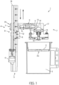
- Fig. 1 - Shows a schematic partial view of a 3D printer according to an embodiment of the invention.
- Fig.1 partially shows a 3D printer according to one embodiment.
- the 3D printer (1) comprises a resin tray (not shown) for holding liquid photopolymer resin to produce a solid component; a component carrier (2) for pulling the component out of the resin tray in layers; a transport box (3) for storing the component carrier (2), the transport box (3) being able to be manually placed or secured at a specific location outside the resin trough; a transport device (4) for removing the component carrier (2) from the transport box (3) and for transporting it into the resin trough, and for moving the component carrier (2) downwards and upwards or sideways in the resin trough.
- the transport device (4) has translational axes (5) in the vertical direction and horizontal direction (not shown), each of which can be independently driven by a motor (6).
- the transport device (4) has a locking device (7) for detachably connecting the component carrier (2).
- the vertical translational axis (5) forms a Z tower (18) in the Z direction, in which the transport device (4) can be set in motion in the Z direction by the motor (6).
- the motor (6) is connected to a Z-arm (17) of the transport device (4) via a threaded screw (19) and threaded nut (20).
- the entire Z-tower (18) is movable in the horizontal direction along a horizontal translational axis (not shown).
- the frame of the Z-tower (18) is connected to the second motor via another threaded screw and threaded nut.
- a coupling element (9) is driven by a on the vertical translational axis (5) located stop (8) is set in motion.
- a spring-loaded locking pin (10) connected to the coupling element (9) is immersed in a bayonet opening (2a) in the component carrier (2).
- the component carrier (2) has a construction platform on the lower side on which printing can be carried out.
- the immersed locking pin (10) can be brought into a locking position in the bayonet opening (2a) via the horizontal translational axis.
- the coupling element (9) is preferably provided in the form of a horizontally movable push rod (11), which can be set in motion by a slope (12) of the stop (8).
- the locking pin (10) is attached to a vertically installed spring-loaded pull rod (13).
- the horizontally movable push rod (11) leads to a downward movement of the locking pin (10) into the component carrier (2) via a slope (14) on the vertically installed spring-loaded pull rod (13).
- the horizontally movable push rod (11) preferably has rollers (15) at both ends for contacting the respective slopes (12; 14).
- a rocker (not shown) can be used instead of the horizontally movable push rod (11).
- the push rod (11) is moved horizontally via the slope (12) located on the Z-tower (18). This movement leads, via the slope (14) on the spring-loaded pull rod (13) installed vertically in the Z-arm (17), to a downward movement of the same and to the release of the locking pin (10).
- the locking pin (10) is immersed in the component carrier (2) and can be brought into the locking position for picking up (or in the unlocking position for depositing) by horizontally moving the Z-tower (18).
- 3D printer (1) preferably has a sensor (not shown) that detects the transport box (3) at the intended location. 3D printer (1) preferably has a further sensor (not shown) which detects the component carrier (2) on the locking device (7) or carries out force measurements.
- the 3D printer (1) has a control device that controls the receiving process of the component carrier (2) from the transport box (3), the transport process of the same into the resin tray, the 3D printing process in the resin tray, the transport process of the same from the resin tray to the transport box (3 ), and automatically controls the depositing process of the component carrier (2) into the transport box (3).
- the component carrier (2) can also be moved obliquely through the vertical and horizontal translational axes.
- the sensor signals are transmitted to the control device. Force sensors, presence and absence sensors can be used as sensors.
- the transport box (3) can be manually placed or assembled outside the resin tub and inside the 3D printer (1) in a separate location or space (not shown).
- the transport box (3) is sealed tightly by the component carrier (2), preferably by means of a seal.
- the transport box (3) can be manually transported together with the component by the user to a post-treatment station (not shown).
- the transport device (4) defined above can be used analogously to transport the component carrier (2) into the aftertreatment chambers.
- Post-treatment chambers can be used to post-expose, wash and/or dry the component.
- the transport box (3) can be made from UV opaque or partially UV transparent material.
Landscapes
- Engineering & Computer Science (AREA)
- Chemical & Material Sciences (AREA)
- Materials Engineering (AREA)
- Manufacturing & Machinery (AREA)
- Physics & Mathematics (AREA)
- Mechanical Engineering (AREA)
- Optics & Photonics (AREA)
- Robotics (AREA)
Description
- Die vorliegende Erfindung bezieht sich auf 3D Drucker, insbesondere auf die Bauplattform des 3D Druckers.
- Laser und DLP basierte 3D Drucker nach dem Prinzip der "over head vatpolymerization" verarbeiten flüssige Photopolymerharze zu festen Bauteilen. Bei diesem Fertigungsprinzip werden die Bauteile schichtweise vertikal aus einer Harzwanne "gezogen". Hierfür sind sie direkt oder indirekt, über eine Stützstruktur, an einen Bauteilträger angebunden. Um Fehler in den Bauteilen zu vermeiden, muss der Bauteilträger während des Druckprozesses fest mit dem 3D Drucker (Z-Kinematik) verbunden sein. Zur Nachbehandlung, nach Beendigung des Druckprozesses, muss das Bauteil mit dem Bauteilträger aus dem 3D Drucker entnommen werden. Hierfür muss die Verbindung zwischen 3D Drucker und Bauteilträger gelöst werden. Vor Beginn des Druckprozesses muss wieder ein Bauteilträger in den 3D-Drucker eingesetzt und fest mit diesem verbunden werden.
- Bei im Markt befindlichen 3D-Druckern wird der Bauteilträger in der Regel manuell durch den Anwender in den Drucker eingesetzt und durch einen Hebelmechanismus oder Schrauben fest mit dem Drucker verbunden. Alternativ kommen auch Robotersysteme zum Einsatz, die den manuellen Part des Anwenders übernehmen.
-
US 2007/077323 A1 offenbart einen 3D Drucker umfassend, eine Harzwanne zur Aufnahme von flüssigem Photopolymerharz zur Herstellung eines festen Bauteils; einen Bauteilträger zum schichtweisen Herausziehen des Bauteils aus der Harzwanne; eine Transportbox zum Ablegen des Bauteilträgers, wobei die Transportbox an einer bestimmten Stelle außerhalb der Harzwanne manuell platziert bzw. befestigt werden kann; eine Transportvorrichtung zum Entnehmen des Bauteilträgers aus der Transportbox und zum Transportieren desselben in die Harzwanne und zum Abwärts-und Aufwärtsbewegen des Bauteilträgers in der Harzwanne , wobei die Transportvorrichtung translatorische Achsen in der vertikalen und horizontalen Richtung aufweist, die jeweils mit einem Motor unabhängig angetrieben werden können, wobei die Transportvorrichtung eine Verriegelungsvorrichtung aufweist zum ablösbaren Verbinden des Bauteilträgers, wobei die Verriegelungsvorrichtung bei der Bewegung entlang der vertikalen translatorischen Achse durch den Antrieb des jeweiligen Motors eine bestimmte Position erreicht, an dem eine, an der vertikalen translatorischen Achse befindlicher Anschlag, ein Kopplungselement in Bewegung setzt wobei ein mit dem Kopplungselement in Verbindung stehender federverspannte Verriegelungspin in eine Verriegelungsposition bzw. Entriegelungsposition gebracht werden kann. - Ein Ziel der vorliegenden Erfindung ist die Bereitstellung eines 3D Druckers mit einer Vorrichtung zur Aufnahme und Fixierung der Bauplattform, die das Aufnehmen/Ablegen der Bauplattform ohne zusätzliche Antriebsmotoren ermöglicht.
- Dieses Ziel wurde durch den 3D Drucker nach Anspruch 1 erreicht. Die Gegenstände der abhängigen Ansprüche beziehen sich auf Weiterentwicklungen und bevorzugte Ausführungsformen.
- Das wesentliche Merkmal der Erfindung liegt in der Nutzung vorhandener translatorischer Bewegungen durch die Motoren zum An- und Abkoppeln des Bauteilträgers vom 3D-Drucker.
- In dem erfindungsgemäßen 3D Drucker werden die im 3D Drucker vorhandenen zwei translatorischen Achsen und deren jeweiligen Motoren genutzt zum Befestigen/Lösen des Bauteilträgers an den 3D-Drucker, zusätzliche Aktuatoren/Motoren werden nicht benötigt. Der Anwender muss lediglich vor dem 3D Drucken den, in der Transportbox abgelegten, Bauteilträger an die vorgesehene Position in den 3D-Drucker stellen/befestigen bzw. nach dem 3D Drucken dort entnehmen, und zur Nachbehandlungsstation tragen.
- In einer bevorzugten Ausführungsform ist das Kopplungselement in Form einer horizontal beweglichen Schubstange bereitgestellt. Bei der Abwärtsbewegung wird die Schubstange durch eine Schräge des Anschlags in Bewegung gesetzt. Der Verriegelungspin ist an einer vertikal eingebauten federverspannten Zugstange angebracht. Die horizontal bewegliche Schubstange führt über eine Schräge an der vertikal eingebauten federverspannten Zugstange zu einer Abwärtsbewegung des Verriegelungspins in den Bauteilträger. Vorzugsweise hat die horizontal bewegliche Schubstange an seinen Beiden Enden Roller zum Kontaktieren der jeweiligen Schrägen.
- In einer alternativen bevorzugten Ausführungsform ist das Kopplungselement in Form einer Wippe bereitgestellt. Bei der Abwärtsbewegung wird die Wippe durch den Anschlag in Bewegung gesetzt. Der Verriegelungspin ist an einer vertikal eingebauten federverspannten Zugstange angebracht. Durch die Bewegung führt die Wippe die vertikal eingebaute federverspannte Zugstange zu einer Abwärtsbewegung des Verriegelungspins in den Bauteilträger.
- In der nachfolgenden Beschreibung wird die vorliegende Erfindung anhand von Ausführungsbeispielen unter Bezugnahme auf die Zeichnung näher erläutert, wobei
Abb. 1 - zeigt eine schematische Teilansicht eines 3D Druckers nach einer Ausführungsform der Erfindung. - Die in den Zeichnungen gezeigten Referenznummern bezeichnen die unten aufgeführten Elemente, auf die in der nachfolgenden Beschreibung der beispielhaften Ausführungsformen Bezug genommen wird.
- 1.
- 3D Drucker
- 2.
- Bauteilträger
- 2a.
- Bajonettöffnung
- 3.
- Transportbox
- 4.
- Transportvorrichtung
- 5.
- Translatorische Achsen
- 6.
- Motor
- 7.
- Verriegelungsvorrichtung
- 8.
- Anschlag
- 9.
- Kopplungselement
- 10.
- Verriegelungspin
- 11.
- Schubstange
- 12.
- Schräge
- 13.
- Zugstange
- 14.
- Schräge
- 15.
- Roller
- 16.
- Feder
- 17.
- Z-Ausleger
- 18.
- Z-Turm
- 19.
- Gewindeschraube
- 20.
- Gewindemutter
-
Abb.1 zeigt teilweise einen 3D Drucker nach einer Ausführungsform. Der 3D Drucker (1) umfasst eine Harzwanne (nicht gezeigt) zur Aufnahme von flüssigem Photopolymerharz zur Herstellung eines festen Bauteils; einen Bauteilträger (2) zum schichtweise Herausziehen des Bauteils aus der Harzwanne; eine Transportbox (3) zum Ablagen des Bauteilträgers (2), wobei die Transportbox (3) an einer bestimmten Stelle außerhalb der Harzwanne manuell platziert bzw. befestigt werden kann; eine Transportvorrichtung (4) zum Entnehmen des Bauteilträgers (2) aus der Transportbox (3) und zum Transportieren desselben in die Harzwanne, und zum Abwärts- und Aufwärtsbewegen bzw. auch Seitwärtsbewegen des Bauteilträger (2) in der Harzwanne. Die Transportvorrichtung (4) weist translatorische Achsen (5) in der vertikalen Richtung und horizontalen Richtung (nicht gezeigt) auf, die jeweils mit einem Motor (6) unabhängig angetrieben werden können. Die Transportvorrichtung (4) weist eine Verriegelungsvorrichtung (7) zum ablösbaren Verbinden des Bauteilträger (2) auf. Die vertikale translatorische Achse (5) bildet einen Z-Turm (18) in der Z-Richtung, in dem die Transportvorrichtung (4) durch den Motor (6) in der Z-Richtung in Bewegung gesetzt werden kann. Der Motor (6) ist mit einem Z-Ausleger (17) der Transportvorrichtung (4) über eine Gewindeschraube (19) und Gewindemutter (20) verbunden. Der gesamte Z-Turm (18) ist über an einer horizontalen translatorischen Achse (nicht gezeigt) in der horizontalen Richtung beweglich. Das Gestell des Z-Turms (18) ist über eine weitere Gewindeschraube und Gewindemutter mit dem zweiten Motor verbunden. Wenn die Verriegelungsvorrichtung (7) bei der Abwärtsbewegung (s. Pfeil nach unten) entlang der vertikalen translatorischen Achse (5) durch den Antrieb des jeweiligen Motors (6) eine bestimmte Position (P) erreicht hat, wird ein Kopplungselement (9) durch einen an der vertikalen translatorischen Achse (5) befindlichen Anschlag (8) in Bewegung gesetzt. Durch die Bewegung wird ein mit dem Kopplungselement (9) in Verbindung stehender federverspannte Verriegelungspin (10) in eine Bajonettöffnung (2a) des Bauteilträgers (2) eingetaucht. Der Bauteilträger (2) weist an der Unteren Seite eine Bauplattform auf, auf dem gedruckt werden kann. Der eingetauchte Verriegelungspins (10) kann über die horizontale translatorische Achse in eine Verriegelungsposition in der Bajonettöffnung (2a) gebracht werden. - Das Kopplungselement (9) ist vorzugsweise in Form einer horizontal beweglichen Schubstange (11) bereitgestellt, die durch eine Schräge (12) des Anschlags (8) in Bewegung gesetzt werden kann. Der Verriegelungspin (10) ist an einer vertikal eingebauten federverspannten Zugstange (13) angebracht. Die horizontal bewegliche Schubstange (11) führt über eine Schräge (14) an der vertikal eingebauten federverspannten Zugstange (13) zu einer Abwärtsbewegung des Verriegelungspins (10) in den Bauteilträger (2). Die horizontal bewegliche Schubstange (11) hat vorzugsweise an seinen beiden Enden Roller (15) zum Kontaktieren der jeweiligen Schrägen (12; 14). Alternativ kann eine Wippe (nicht gezeigt) an Stelle der horizontal beweglichen Schubstange (11) benutzt werden.
- In der folgenden Beschreibung wird die Funktionsweise (Aufnahme/Ablage) nach einer Ausführungsform detailliert erklärt:
- Erreicht der Z-Ausleger (17) bei der Abwärtsbewegung am Z-Turm (18) eine bestimmte Position (P), wird über die am Z-Turm (18) befindliche Schräge (12) die Schubstange (11) horizontal bewegt. Diese Bewegung führt, über die Schräge (14) an der vertikal im Z-Ausleger (17) eingebauten federverspannten Zugstange (13), zu einer Abwärtsbewegung derselben und zur Freigabe des Verriegelungspins (10). Der Verriegelungspin (10) taucht in den Bauteilträger (2) ein und kann über eine horizontale Bewegung des Z-Turms (18) in die Verriegelungsposition zum Aufnehmen (bzw. in die Entriegelungsposition zum Ablegen) gebracht werden.
- Bei der Aufwärtsbewegung des Z-Auslegers (17) bleibt der Bauteilträger (2) in der Verriegelungsposition am Verriegelungspin (10) hängen und wird aus der Transportbox (3) entnommen. Im Bereich der Schräge (12) am Z-Turm (17) gibt die Schubstange (11) nun die Zugstange (13) frei und diese zieht über die Federspannung (16) den Bauteilträger (2) bzw. die Bauplattform fest an den Z-Ausleger (17).
- 3D Drucker (1) hat vorzugsweise einen Sensor (nicht gezeigt) der die Transportbox (3) an der vorgesehenen Stelle detektiert. 3D Drucker (1) hat vorzugsweise einen weiteren Sensor (nicht gezeigt) die den Bauteilträger (2) an der Verriegelungsvorrichtung (7) detektiert bzw. Kraftmessungen durchführt. Der 3D Drucker (1) weist eine Steuerungsvorrichtung auf, die den Aufnahmevorgang des Bauteilträgers (2) aus der Transportbox (3), den Transportvorgang desselben in die Harzwanne, den 3D Druckvorgang in der Harzwanne, den Transportvorgang desselben aus der Harzwanne zur Transportbox (3), und den Ablagevorgang des Bauteilträgers (2) in die Transportbox (3) automatisch steuert. Beim 3D Drucken kann der Bauteilträger (2) auch durch die vertikale und horizontale translatorischen Achsen schräg gefahren werden. Die Sensorsignale werden an die Steuerungsvorrichtung übermittelt. Als Sensoren können Kraftsensoren, Anwesenheits- und Abwesenheitssensoren verwendet werden.
- Die Transportbox (3) kann außerhalb der Harzwanne und innerhalb des 3D Druckers (1) in einem dazu vorgesehen separaten Stelle bzw. Raum (nicht gezeigt) manuell platziert bzw. montiert werden. Die Transportbox (3) wird von dem Bauteilträger (2) vorzugsweise mittels einer Dichtung dicht verschlossen. Die Transportbox (3) kann nach dem 3D Drucken zusammen mit dem Bauteil, durch den Anwender zu einer Nachbehandlungsstation (nicht gezeigt) manuell transportiert werden. In der Nachbehandlungsstation kann die oben definierte Transportvorrichtung (4) analog verwendet werden um den Bauteilträger (2) in die Nachbehandlungskammern zu transportieren. Nachbehandlungskammern können benutzt werden um das Bauteil nachzubelichten, zu waschen, und/oder zu trocknen. Die Transportbox (3) kann aus UV opakem oder teilweise aus UV transparentem Material hergestellt werden. Vorzugsweise ist eine Dichtung zwischen dem Bauteilträger (2) und der Öffnung der Transportbox (3) vorhanden, die gegen UV-Strahlung und Flüssigkeitsaustritt abdichtet.
Claims (4)
- 3D Drucker (1) umfassend,eine Harzwanne zur Aufnahme von flüssigem Photopolymerharz zur Herstellung eines festen Bauteils;einen Bauteilträger (2) zum schichtweisen Herausziehen des Bauteils aus der Harzwanne, wobei der Bauteilträger eine Bajonettöffnung aufweist;eine Transportbox (3) zum Ablegen des Bauteilträgers (2), wobei die Transportbox (3) an einer bestimmten Stelle außerhalb der Harzwanne manuell platziert bzw. befestigt werden kann,eine Transportvorrichtung (4) zum Entnehmen des Bauteilträgers (2) aus der Transportbox (3) und zum Transportieren desselben in die Harzwanne, und zum Abwärts-und Aufwärtsbewegen bzw. auch Seitwärtsbewegen des Bauteilträgers (2) in der Harzwanne,wobei die Transportvorrichtung (4) translatorische Achsen (5) in der vertikalen und horizontalen Richtung aufweist, die jeweils mit einem Motor (6) unabhängig angetrieben werden können,wobei die Transportvorrichtung (4) eine Verriegelungsvorrichtung (7) aufweist zum ablösbaren Verbinden des Bauteilträgers (2),wobei die Verriegelungsvorrichtung (7) derart ausgebildet ist, dass sie bei der Abwärtsbewegung entlang der vertikalen translatorischen Achse (5) durch den Antrieb des jeweiligen Motors (6) eine bestimmte Position (P) erreicht, an dem eine, an der vertikalen translatorischen Achse (5) befindlicher Anschlag (8), ein Kopplungselement (9) in Bewegung setzt, wobei ein mit dem Kopplungselement (9) in Verbindung stehender federverspannte Verriegelungspin (10) durch die Bewegung in die Bajonettöffnung (2a) des Bauteilträgers (2) eingetaucht wird,wobei der eingetauchte Verriegelungspins (10) über die horizontale translatorische Achse in eine Verriegelungsposition bzw. Entriegelungsposition in der Bajonettöffnung (2a) gebracht wird.
- Der 3D Drucker (1) nach Anspruch 1, gekennzeichnet dadurch, dass
das Kopplungselement (9) eine horizontal bewegliche Schubstange (11) aufweist, die durch eine Schräge (12) des Anschlags (8) in Bewegung gesetzt wird, wobei der Verriegelungspin (10) an einer vertikal eingebauten federverspannten Zugstange (13) angebracht ist, und wobei die horizontal bewegliche Schubstange (11) über eine Schräge (14) an der vertikal eingebauten federverspannten Zugstange (13) zu einer Abwärtsbewegung des Verriegelungspins (10) in den Bauteilträger (2) führt. - Der 3D Drucker (1) nach Anspruch 2, gekennzeichnet dadurch, dass die horizontal bewegliche Schubstange (11) an seinen beiden Enden Roller (15) aufweist, zum Kontaktieren der jeweiligen Schrägen (12; 14).
- Der 3D Drucker nach Anspruch 1, gekennzeichnet dadurch, dass
das Kopplungselement (9) eine Wippe aufweist, die durch den Anschlag (8) bei Abwärtsbewegung in Bewegung gesetzt wird, wobei der Verriegelungspin (10) an einer vertikal eingebauten federverspannten Zugstange (13) angebracht ist, und wobei die Wippe die vertikal eingebauten federverspannten Zugstange (13) zu einer Abwärtsbewegung des Verriegelungspins (10) in den Bauteilträger (1) führt.
Priority Applications (10)
| Application Number | Priority Date | Filing Date | Title |
|---|---|---|---|
| EP21184953.4A EP4119331B1 (de) | 2021-07-12 | 2021-07-12 | Vorrichtung zur aufnahme und fixierung des bauteilträgers eines 3d-druckers unter ausnutzung vorhandener bewegungsachsen |
| KR1020247001575A KR20240032034A (ko) | 2021-07-12 | 2022-06-27 | 기존의 이동 축을 활용하여 3d 프린터의 구성요소 캐리어를 수용 및 고정하는 장치 |
| CN202280049356.7A CN117642276A (zh) | 2021-07-12 | 2022-06-27 | 利用现有运动轴来接纳和固定3d打印机的组分载体的装置 |
| CA3226392A CA3226392A1 (en) | 2021-07-12 | 2022-06-27 | Device for receiving and fixing the component carrier of a 3d printer by utilizing existing axes of motion |
| JP2024501654A JP7837118B2 (ja) | 2021-07-12 | 2022-06-27 | 既存の運動軸を利用することによって3dプリンタの部品担体を受容及び固定するための装置 |
| PCT/EP2022/067577 WO2023285125A1 (en) | 2021-07-12 | 2022-06-27 | Device for receiving and fixing the component carrier of a 3d printer by utilizing existing axes of motion |
| US18/578,136 US12454098B2 (en) | 2021-07-12 | 2022-06-27 | Device for receiving and fixing the component carrier of a 3D printer by utilitizing existing axes of motion |
| BR112023026170A BR112023026170A2 (pt) | 2021-07-12 | 2022-06-27 | Dispositivo para receber e fixar o componente transportador de uma impressora 3d utilizando eixos de movimento existentes |
| AU2022310554A AU2022310554A1 (en) | 2021-07-12 | 2022-06-27 | Device for receiving and fixing the component carrier of a 3d printer by utilizing existing axes of motion |
| US19/338,879 US20260145382A1 (en) | 2021-07-12 | 2025-09-24 | Device for receiving and fixing the component carrier of a 3d printer by utilizing existing axes of motion |
Applications Claiming Priority (1)
| Application Number | Priority Date | Filing Date | Title |
|---|---|---|---|
| EP21184953.4A EP4119331B1 (de) | 2021-07-12 | 2021-07-12 | Vorrichtung zur aufnahme und fixierung des bauteilträgers eines 3d-druckers unter ausnutzung vorhandener bewegungsachsen |
Publications (2)
| Publication Number | Publication Date |
|---|---|
| EP4119331A1 EP4119331A1 (de) | 2023-01-18 |
| EP4119331B1 true EP4119331B1 (de) | 2024-02-28 |
Family
ID=76890825
Family Applications (1)
| Application Number | Title | Priority Date | Filing Date |
|---|---|---|---|
| EP21184953.4A Active EP4119331B1 (de) | 2021-07-12 | 2021-07-12 | Vorrichtung zur aufnahme und fixierung des bauteilträgers eines 3d-druckers unter ausnutzung vorhandener bewegungsachsen |
Country Status (9)
| Country | Link |
|---|---|
| US (2) | US12454098B2 (de) |
| EP (1) | EP4119331B1 (de) |
| JP (1) | JP7837118B2 (de) |
| KR (1) | KR20240032034A (de) |
| CN (1) | CN117642276A (de) |
| AU (1) | AU2022310554A1 (de) |
| BR (1) | BR112023026170A2 (de) |
| CA (1) | CA3226392A1 (de) |
| WO (1) | WO2023285125A1 (de) |
Family Cites Families (6)
| Publication number | Priority date | Publication date | Assignee | Title |
|---|---|---|---|---|
| GB1231989A (de) * | 1969-03-31 | 1971-05-12 | ||
| DE3133297A1 (de) * | 1981-08-22 | 1983-03-03 | Olympia Werke Ag, 2940 Wilhelmshaven | Verfahren und vorrichtung zur papierfuehrung in schreib- oder aehnlichen bueromaschinen |
| CA2487217A1 (en) * | 2004-11-12 | 2006-05-12 | Fahrzeugtechnik Dessau Ag - Railroad Technologies | Locking and unlocking device for vehicle doors, in particular swinging sliding doors for rail vehicles |
| US20070077323A1 (en) * | 2005-09-30 | 2007-04-05 | 3D Systems, Inc. | Rapid prototyping and manufacturing system and method |
| TWI592289B (zh) | 2014-12-23 | 2017-07-21 | Dws有限責任公司 | 具有促進初始化的光固化機 |
| CN110625930A (zh) * | 2018-06-21 | 2019-12-31 | 中南大学 | 一种快速光固化的lcd 3d打印机 |
-
2021
- 2021-07-12 EP EP21184953.4A patent/EP4119331B1/de active Active
-
2022
- 2022-06-27 BR BR112023026170A patent/BR112023026170A2/pt unknown
- 2022-06-27 CA CA3226392A patent/CA3226392A1/en active Pending
- 2022-06-27 WO PCT/EP2022/067577 patent/WO2023285125A1/en not_active Ceased
- 2022-06-27 AU AU2022310554A patent/AU2022310554A1/en active Pending
- 2022-06-27 JP JP2024501654A patent/JP7837118B2/ja active Active
- 2022-06-27 KR KR1020247001575A patent/KR20240032034A/ko not_active Abandoned
- 2022-06-27 CN CN202280049356.7A patent/CN117642276A/zh active Pending
- 2022-06-27 US US18/578,136 patent/US12454098B2/en active Active
-
2025
- 2025-09-24 US US19/338,879 patent/US20260145382A1/en active Pending
Also Published As
| Publication number | Publication date |
|---|---|
| JP2024525712A (ja) | 2024-07-12 |
| US12454098B2 (en) | 2025-10-28 |
| JP7837118B2 (ja) | 2026-03-30 |
| BR112023026170A2 (pt) | 2024-03-05 |
| CA3226392A1 (en) | 2023-01-19 |
| US20250114998A1 (en) | 2025-04-10 |
| KR20240032034A (ko) | 2024-03-08 |
| US20260145382A1 (en) | 2026-05-28 |
| EP4119331A1 (de) | 2023-01-18 |
| WO2023285125A1 (en) | 2023-01-19 |
| CN117642276A (zh) | 2024-03-01 |
| AU2022310554A1 (en) | 2024-01-04 |
Similar Documents
| Publication | Publication Date | Title |
|---|---|---|
| DE69724088T2 (de) | Messvorrichtung zur vereinfachung des montierens und auswechselns eines behälters | |
| DE69009120T2 (de) | Automatisches Reinigungsgerät für Scheiben. | |
| DE69710262T2 (de) | Nachfüllverfahren und -gerät für Druckpatrone | |
| EP2449358B1 (de) | Vorrichtung zur wasserprobennahme | |
| DE4131667C2 (de) | Vorrichtung zum Entfernen von Fadenresten | |
| DE69320139T2 (de) | Tintenstrahlkopf-Kartusche und Tintenstrahlgerät mit dieser Kartusche | |
| DE112015004380T5 (de) | Wischmechanismus, flüssigkeitströpfchenstrahl-vorrichtung und wischverfahren | |
| DE69109705T2 (de) | Aufzeichnungsgerät mit Tintenstrahlaufzeichnungskopf. | |
| DE10147999B4 (de) | Tintenstrahlabdeckung mit Entlüftungsöffnung | |
| DE2930628A1 (de) | Antriebsgeraet fuer einen ultraschall- fehlerdetektor | |
| DE69508454T2 (de) | Verbesserte Reinigungsvorrichtung und ein damit versehenes Tintenstrahlaufzeichnungsgerät | |
| DE102018203290A1 (de) | Behälter zum Transport eines Luftfahrzeugs und Transportverfahren | |
| EP3686061A1 (de) | Adapter für ein kraftfahrzeug | |
| EP1243466B1 (de) | Transportsicherung für Frachtcontainer | |
| DE69826575T2 (de) | Tintenstrahldrucker | |
| EP4119331A1 (de) | Vorrichtung zur aufnahme und fixierung des bauteilträgers eines 3d-druckers unter ausnutzung vorhandener bewegungsachsen | |
| EP0382909A2 (de) | Belastungsträger für Streckwerke | |
| DE2944102C2 (de) | Langholzträger | |
| DE69620862T2 (de) | Farbstrahldrucker | |
| DE202024000293U1 (de) | Räderwaschanlage | |
| EP0450038B1 (de) | Verfahren und vorrichtung zur montage einer wischanlage | |
| DE3227714C1 (de) | Vorrichtung fuer Farb- und Korrekturband in Schreibmaschinen | |
| DE102011007195B4 (de) | Tintenauffangvorrichtung für einen Tintenstrahldrucker | |
| DE3613963C2 (de) | ||
| DE102025122734A1 (de) | Wagenkupplungsvorrichtung |
Legal Events
| Date | Code | Title | Description |
|---|---|---|---|
| PUAI | Public reference made under article 153(3) epc to a published international application that has entered the european phase |
Free format text: ORIGINAL CODE: 0009012 |
|
| STAA | Information on the status of an ep patent application or granted ep patent |
Free format text: STATUS: THE APPLICATION HAS BEEN PUBLISHED |
|
| AK | Designated contracting states |
Kind code of ref document: A1 Designated state(s): AL AT BE BG CH CY CZ DE DK EE ES FI FR GB GR HR HU IE IS IT LI LT LU LV MC MK MT NL NO PL PT RO RS SE SI SK SM TR |
|
| STAA | Information on the status of an ep patent application or granted ep patent |
Free format text: STATUS: REQUEST FOR EXAMINATION WAS MADE |
|
| P01 | Opt-out of the competence of the unified patent court (upc) registered |
Effective date: 20230524 |
|
| 17P | Request for examination filed |
Effective date: 20230621 |
|
| RBV | Designated contracting states (corrected) |
Designated state(s): AL AT BE BG CH CY CZ DE DK EE ES FI FR GB GR HR HU IE IS IT LI LT LU LV MC MK MT NL NO PL PT RO RS SE SI SK SM TR |
|
| GRAP | Despatch of communication of intention to grant a patent |
Free format text: ORIGINAL CODE: EPIDOSNIGR1 |
|
| STAA | Information on the status of an ep patent application or granted ep patent |
Free format text: STATUS: GRANT OF PATENT IS INTENDED |
|
| INTG | Intention to grant announced |
Effective date: 20231016 |
|
| GRAS | Grant fee paid |
Free format text: ORIGINAL CODE: EPIDOSNIGR3 |
|
| GRAA | (expected) grant |
Free format text: ORIGINAL CODE: 0009210 |
|
| STAA | Information on the status of an ep patent application or granted ep patent |
Free format text: STATUS: THE PATENT HAS BEEN GRANTED |
|
| AK | Designated contracting states |
Kind code of ref document: B1 Designated state(s): AL AT BE BG CH CY CZ DE DK EE ES FI FR GB GR HR HU IE IS IT LI LT LU LV MC MK MT NL NO PL PT RO RS SE SI SK SM TR |
|
| REG | Reference to a national code |
Ref country code: GB Ref legal event code: FG4D Free format text: NOT ENGLISH |
|
| REG | Reference to a national code |
Ref country code: CH Ref legal event code: EP |
|
| REG | Reference to a national code |
Ref country code: DE Ref legal event code: R096 Ref document number: 502021002808 Country of ref document: DE |
|
| REG | Reference to a national code |
Ref country code: IE Ref legal event code: FG4D Free format text: LANGUAGE OF EP DOCUMENT: GERMAN |
|
| REG | Reference to a national code |
Ref country code: LT Ref legal event code: MG9D |
|
| PG25 | Lapsed in a contracting state [announced via postgrant information from national office to epo] |
Ref country code: IS Free format text: LAPSE BECAUSE OF FAILURE TO SUBMIT A TRANSLATION OF THE DESCRIPTION OR TO PAY THE FEE WITHIN THE PRESCRIBED TIME-LIMIT Effective date: 20240628 |
|
| REG | Reference to a national code |
Ref country code: NL Ref legal event code: MP Effective date: 20240228 |
|
| PG25 | Lapsed in a contracting state [announced via postgrant information from national office to epo] |
Ref country code: LT Free format text: LAPSE BECAUSE OF FAILURE TO SUBMIT A TRANSLATION OF THE DESCRIPTION OR TO PAY THE FEE WITHIN THE PRESCRIBED TIME-LIMIT Effective date: 20240228 |
|
| PG25 | Lapsed in a contracting state [announced via postgrant information from national office to epo] |
Ref country code: GR Free format text: LAPSE BECAUSE OF FAILURE TO SUBMIT A TRANSLATION OF THE DESCRIPTION OR TO PAY THE FEE WITHIN THE PRESCRIBED TIME-LIMIT Effective date: 20240529 |
|
| PG25 | Lapsed in a contracting state [announced via postgrant information from national office to epo] |
Ref country code: RS Free format text: LAPSE BECAUSE OF FAILURE TO SUBMIT A TRANSLATION OF THE DESCRIPTION OR TO PAY THE FEE WITHIN THE PRESCRIBED TIME-LIMIT Effective date: 20240528 Ref country code: NL Free format text: LAPSE BECAUSE OF FAILURE TO SUBMIT A TRANSLATION OF THE DESCRIPTION OR TO PAY THE FEE WITHIN THE PRESCRIBED TIME-LIMIT Effective date: 20240228 Ref country code: HR Free format text: LAPSE BECAUSE OF FAILURE TO SUBMIT A TRANSLATION OF THE DESCRIPTION OR TO PAY THE FEE WITHIN THE PRESCRIBED TIME-LIMIT Effective date: 20240228 |
|
| PG25 | Lapsed in a contracting state [announced via postgrant information from national office to epo] |
Ref country code: ES Free format text: LAPSE BECAUSE OF FAILURE TO SUBMIT A TRANSLATION OF THE DESCRIPTION OR TO PAY THE FEE WITHIN THE PRESCRIBED TIME-LIMIT Effective date: 20240228 |
|
| PG25 | Lapsed in a contracting state [announced via postgrant information from national office to epo] |
Ref country code: RS Free format text: LAPSE BECAUSE OF FAILURE TO SUBMIT A TRANSLATION OF THE DESCRIPTION OR TO PAY THE FEE WITHIN THE PRESCRIBED TIME-LIMIT Effective date: 20240528 Ref country code: NO Free format text: LAPSE BECAUSE OF FAILURE TO SUBMIT A TRANSLATION OF THE DESCRIPTION OR TO PAY THE FEE WITHIN THE PRESCRIBED TIME-LIMIT Effective date: 20240528 Ref country code: NL Free format text: LAPSE BECAUSE OF FAILURE TO SUBMIT A TRANSLATION OF THE DESCRIPTION OR TO PAY THE FEE WITHIN THE PRESCRIBED TIME-LIMIT Effective date: 20240228 Ref country code: LT Free format text: LAPSE BECAUSE OF FAILURE TO SUBMIT A TRANSLATION OF THE DESCRIPTION OR TO PAY THE FEE WITHIN THE PRESCRIBED TIME-LIMIT Effective date: 20240228 Ref country code: IS Free format text: LAPSE BECAUSE OF FAILURE TO SUBMIT A TRANSLATION OF THE DESCRIPTION OR TO PAY THE FEE WITHIN THE PRESCRIBED TIME-LIMIT Effective date: 20240628 Ref country code: HR Free format text: LAPSE BECAUSE OF FAILURE TO SUBMIT A TRANSLATION OF THE DESCRIPTION OR TO PAY THE FEE WITHIN THE PRESCRIBED TIME-LIMIT Effective date: 20240228 Ref country code: GR Free format text: LAPSE BECAUSE OF FAILURE TO SUBMIT A TRANSLATION OF THE DESCRIPTION OR TO PAY THE FEE WITHIN THE PRESCRIBED TIME-LIMIT Effective date: 20240529 Ref country code: FI Free format text: LAPSE BECAUSE OF FAILURE TO SUBMIT A TRANSLATION OF THE DESCRIPTION OR TO PAY THE FEE WITHIN THE PRESCRIBED TIME-LIMIT Effective date: 20240228 Ref country code: ES Free format text: LAPSE BECAUSE OF FAILURE TO SUBMIT A TRANSLATION OF THE DESCRIPTION OR TO PAY THE FEE WITHIN THE PRESCRIBED TIME-LIMIT Effective date: 20240228 Ref country code: BG Free format text: LAPSE BECAUSE OF FAILURE TO SUBMIT A TRANSLATION OF THE DESCRIPTION OR TO PAY THE FEE WITHIN THE PRESCRIBED TIME-LIMIT Effective date: 20240228 |
|
| PG25 | Lapsed in a contracting state [announced via postgrant information from national office to epo] |
Ref country code: PT Free format text: LAPSE BECAUSE OF FAILURE TO SUBMIT A TRANSLATION OF THE DESCRIPTION OR TO PAY THE FEE WITHIN THE PRESCRIBED TIME-LIMIT Effective date: 20240628 Ref country code: PL Free format text: LAPSE BECAUSE OF FAILURE TO SUBMIT A TRANSLATION OF THE DESCRIPTION OR TO PAY THE FEE WITHIN THE PRESCRIBED TIME-LIMIT Effective date: 20240228 |
|
| PG25 | Lapsed in a contracting state [announced via postgrant information from national office to epo] |
Ref country code: SE Free format text: LAPSE BECAUSE OF FAILURE TO SUBMIT A TRANSLATION OF THE DESCRIPTION OR TO PAY THE FEE WITHIN THE PRESCRIBED TIME-LIMIT Effective date: 20240228 Ref country code: PT Free format text: LAPSE BECAUSE OF FAILURE TO SUBMIT A TRANSLATION OF THE DESCRIPTION OR TO PAY THE FEE WITHIN THE PRESCRIBED TIME-LIMIT Effective date: 20240628 Ref country code: PL Free format text: LAPSE BECAUSE OF FAILURE TO SUBMIT A TRANSLATION OF THE DESCRIPTION OR TO PAY THE FEE WITHIN THE PRESCRIBED TIME-LIMIT Effective date: 20240228 Ref country code: LV Free format text: LAPSE BECAUSE OF FAILURE TO SUBMIT A TRANSLATION OF THE DESCRIPTION OR TO PAY THE FEE WITHIN THE PRESCRIBED TIME-LIMIT Effective date: 20240228 |
|
| PG25 | Lapsed in a contracting state [announced via postgrant information from national office to epo] |
Ref country code: DK Free format text: LAPSE BECAUSE OF FAILURE TO SUBMIT A TRANSLATION OF THE DESCRIPTION OR TO PAY THE FEE WITHIN THE PRESCRIBED TIME-LIMIT Effective date: 20240228 |
|
| PG25 | Lapsed in a contracting state [announced via postgrant information from national office to epo] |
Ref country code: SM Free format text: LAPSE BECAUSE OF FAILURE TO SUBMIT A TRANSLATION OF THE DESCRIPTION OR TO PAY THE FEE WITHIN THE PRESCRIBED TIME-LIMIT Effective date: 20240228 |
|
| PG25 | Lapsed in a contracting state [announced via postgrant information from national office to epo] |
Ref country code: CZ Free format text: LAPSE BECAUSE OF FAILURE TO SUBMIT A TRANSLATION OF THE DESCRIPTION OR TO PAY THE FEE WITHIN THE PRESCRIBED TIME-LIMIT Effective date: 20240228 Ref country code: EE Free format text: LAPSE BECAUSE OF FAILURE TO SUBMIT A TRANSLATION OF THE DESCRIPTION OR TO PAY THE FEE WITHIN THE PRESCRIBED TIME-LIMIT Effective date: 20240228 |
|
| PG25 | Lapsed in a contracting state [announced via postgrant information from national office to epo] |
Ref country code: SK Free format text: LAPSE BECAUSE OF FAILURE TO SUBMIT A TRANSLATION OF THE DESCRIPTION OR TO PAY THE FEE WITHIN THE PRESCRIBED TIME-LIMIT Effective date: 20240228 |
|
| PG25 | Lapsed in a contracting state [announced via postgrant information from national office to epo] |
Ref country code: SM Free format text: LAPSE BECAUSE OF FAILURE TO SUBMIT A TRANSLATION OF THE DESCRIPTION OR TO PAY THE FEE WITHIN THE PRESCRIBED TIME-LIMIT Effective date: 20240228 Ref country code: SK Free format text: LAPSE BECAUSE OF FAILURE TO SUBMIT A TRANSLATION OF THE DESCRIPTION OR TO PAY THE FEE WITHIN THE PRESCRIBED TIME-LIMIT Effective date: 20240228 Ref country code: RO Free format text: LAPSE BECAUSE OF FAILURE TO SUBMIT A TRANSLATION OF THE DESCRIPTION OR TO PAY THE FEE WITHIN THE PRESCRIBED TIME-LIMIT Effective date: 20240228 Ref country code: EE Free format text: LAPSE BECAUSE OF FAILURE TO SUBMIT A TRANSLATION OF THE DESCRIPTION OR TO PAY THE FEE WITHIN THE PRESCRIBED TIME-LIMIT Effective date: 20240228 Ref country code: DK Free format text: LAPSE BECAUSE OF FAILURE TO SUBMIT A TRANSLATION OF THE DESCRIPTION OR TO PAY THE FEE WITHIN THE PRESCRIBED TIME-LIMIT Effective date: 20240228 Ref country code: CZ Free format text: LAPSE BECAUSE OF FAILURE TO SUBMIT A TRANSLATION OF THE DESCRIPTION OR TO PAY THE FEE WITHIN THE PRESCRIBED TIME-LIMIT Effective date: 20240228 |
|
| REG | Reference to a national code |
Ref country code: DE Ref legal event code: R097 Ref document number: 502021002808 Country of ref document: DE |
|
| PG25 | Lapsed in a contracting state [announced via postgrant information from national office to epo] |
Ref country code: IT Free format text: LAPSE BECAUSE OF FAILURE TO SUBMIT A TRANSLATION OF THE DESCRIPTION OR TO PAY THE FEE WITHIN THE PRESCRIBED TIME-LIMIT Effective date: 20240228 |
|
| PG25 | Lapsed in a contracting state [announced via postgrant information from national office to epo] |
Ref country code: IT Free format text: LAPSE BECAUSE OF FAILURE TO SUBMIT A TRANSLATION OF THE DESCRIPTION OR TO PAY THE FEE WITHIN THE PRESCRIBED TIME-LIMIT Effective date: 20240228 |
|
| PLBE | No opposition filed within time limit |
Free format text: ORIGINAL CODE: 0009261 |
|
| STAA | Information on the status of an ep patent application or granted ep patent |
Free format text: STATUS: NO OPPOSITION FILED WITHIN TIME LIMIT |
|
| 26N | No opposition filed |
Effective date: 20241129 |
|
| PG25 | Lapsed in a contracting state [announced via postgrant information from national office to epo] |
Ref country code: MC Free format text: LAPSE BECAUSE OF FAILURE TO SUBMIT A TRANSLATION OF THE DESCRIPTION OR TO PAY THE FEE WITHIN THE PRESCRIBED TIME-LIMIT Effective date: 20240228 |
|
| PG25 | Lapsed in a contracting state [announced via postgrant information from national office to epo] |
Ref country code: LU Free format text: LAPSE BECAUSE OF NON-PAYMENT OF DUE FEES Effective date: 20240712 |
|
| PG25 | Lapsed in a contracting state [announced via postgrant information from national office to epo] |
Ref country code: LU Free format text: LAPSE BECAUSE OF NON-PAYMENT OF DUE FEES Effective date: 20240712 |
|
| PG25 | Lapsed in a contracting state [announced via postgrant information from national office to epo] |
Ref country code: SI Free format text: LAPSE BECAUSE OF FAILURE TO SUBMIT A TRANSLATION OF THE DESCRIPTION OR TO PAY THE FEE WITHIN THE PRESCRIBED TIME-LIMIT Effective date: 20240228 Ref country code: BE Free format text: LAPSE BECAUSE OF NON-PAYMENT OF DUE FEES Effective date: 20240731 |
|
| REG | Reference to a national code |
Ref country code: BE Ref legal event code: MM Effective date: 20240731 |
|
| PG25 | Lapsed in a contracting state [announced via postgrant information from national office to epo] |
Ref country code: IE Free format text: LAPSE BECAUSE OF NON-PAYMENT OF DUE FEES Effective date: 20240712 |
|
| PGFP | Annual fee paid to national office [announced via postgrant information from national office to epo] |
Ref country code: DE Payment date: 20250620 Year of fee payment: 5 |
|
| PGFP | Annual fee paid to national office [announced via postgrant information from national office to epo] |
Ref country code: AT Payment date: 20251020 Year of fee payment: 5 |
|
| PGFP | Annual fee paid to national office [announced via postgrant information from national office to epo] |
Ref country code: CH Payment date: 20250801 Year of fee payment: 5 |
|
| PG25 | Lapsed in a contracting state [announced via postgrant information from national office to epo] |
Ref country code: CY Free format text: LAPSE BECAUSE OF FAILURE TO SUBMIT A TRANSLATION OF THE DESCRIPTION OR TO PAY THE FEE WITHIN THE PRESCRIBED TIME-LIMIT; INVALID AB INITIO Effective date: 20210712 |
|
| PG25 | Lapsed in a contracting state [announced via postgrant information from national office to epo] |
Ref country code: HU Free format text: LAPSE BECAUSE OF FAILURE TO SUBMIT A TRANSLATION OF THE DESCRIPTION OR TO PAY THE FEE WITHIN THE PRESCRIBED TIME-LIMIT; INVALID AB INITIO Effective date: 20210712 |
|
| PG25 | Lapsed in a contracting state [announced via postgrant information from national office to epo] |
Ref country code: TR Free format text: LAPSE BECAUSE OF FAILURE TO SUBMIT A TRANSLATION OF THE DESCRIPTION OR TO PAY THE FEE WITHIN THE PRESCRIBED TIME-LIMIT Effective date: 20240228 |
|
| PGFP | Annual fee paid to national office [announced via postgrant information from national office to epo] |
Ref country code: GB Payment date: 20260618 Year of fee payment: 6 |
|
| PGFP | Annual fee paid to national office [announced via postgrant information from national office to epo] |
Ref country code: FR Payment date: 20260618 Year of fee payment: 6 |
|
| REG | Reference to a national code |
Ref country code: CH Ref legal event code: U11 Free format text: ST27 STATUS EVENT CODE: U-0-0-U10-U11 (AS PROVIDED BY THE NATIONAL OFFICE) Effective date: 20260801 |