EP4119320A1 - Procédé et dispositif de préparation, de traitement et/ou de recyclage de matériaux - Google Patents
Procédé et dispositif de préparation, de traitement et/ou de recyclage de matériaux Download PDFInfo
- Publication number
- EP4119320A1 EP4119320A1 EP22192112.5A EP22192112A EP4119320A1 EP 4119320 A1 EP4119320 A1 EP 4119320A1 EP 22192112 A EP22192112 A EP 22192112A EP 4119320 A1 EP4119320 A1 EP 4119320A1
- Authority
- EP
- European Patent Office
- Prior art keywords
- receptacle
- measured
- electromagnetic radiation
- lumpy
- mixing
- Prior art date
- Legal status (The legal status is an assumption and is not a legal conclusion. Google has not performed a legal analysis and makes no representation as to the accuracy of the status listed.)
- Pending
Links
- 239000000463 material Substances 0.000 title claims abstract description 381
- 238000012545 processing Methods 0.000 title claims abstract description 94
- 238000000034 method Methods 0.000 title claims abstract description 93
- 238000004064 recycling Methods 0.000 title claims abstract description 19
- 238000001228 spectrum Methods 0.000 claims abstract description 89
- 230000005670 electromagnetic radiation Effects 0.000 claims abstract description 84
- 238000002156 mixing Methods 0.000 claims abstract description 65
- 239000011236 particulate material Substances 0.000 claims abstract description 42
- 230000000704 physical effect Effects 0.000 claims abstract description 39
- 239000012815 thermoplastic material Substances 0.000 claims abstract description 14
- 239000002245 particle Substances 0.000 claims description 64
- 230000005284 excitation Effects 0.000 claims description 53
- 238000011156 evaluation Methods 0.000 claims description 15
- 239000004033 plastic Substances 0.000 claims description 15
- 229920003023 plastic Polymers 0.000 claims description 15
- 238000012937 correction Methods 0.000 claims description 13
- 238000011049 filling Methods 0.000 claims description 12
- 230000035515 penetration Effects 0.000 claims description 9
- 230000005855 radiation Effects 0.000 claims description 8
- 230000002093 peripheral effect Effects 0.000 claims description 6
- 239000011521 glass Substances 0.000 claims description 5
- 229910052594 sapphire Inorganic materials 0.000 claims description 5
- 239000010980 sapphire Substances 0.000 claims description 5
- 238000011144 upstream manufacturing Methods 0.000 claims description 5
- 230000001419 dependent effect Effects 0.000 claims description 4
- 238000005259 measurement Methods 0.000 abstract description 85
- 238000006243 chemical reaction Methods 0.000 abstract description 16
- 230000000694 effects Effects 0.000 abstract description 11
- 238000004891 communication Methods 0.000 abstract description 7
- 230000008569 process Effects 0.000 description 44
- 238000001069 Raman spectroscopy Methods 0.000 description 28
- 229920000642 polymer Polymers 0.000 description 25
- 238000004886 process control Methods 0.000 description 20
- 239000004698 Polyethylene Substances 0.000 description 18
- 239000000945 filler Substances 0.000 description 16
- 239000000203 mixture Substances 0.000 description 15
- 238000004458 analytical method Methods 0.000 description 12
- 239000007795 chemical reaction product Substances 0.000 description 12
- 238000004497 NIR spectroscopy Methods 0.000 description 11
- 239000008187 granular material Substances 0.000 description 11
- 238000004519 manufacturing process Methods 0.000 description 11
- 239000000835 fiber Substances 0.000 description 10
- 238000002360 preparation method Methods 0.000 description 10
- 239000000523 sample Substances 0.000 description 10
- 238000012360 testing method Methods 0.000 description 10
- 230000009471 action Effects 0.000 description 8
- 230000008859 change Effects 0.000 description 8
- 238000012544 monitoring process Methods 0.000 description 8
- 238000000053 physical method Methods 0.000 description 8
- 230000003287 optical effect Effects 0.000 description 6
- 239000000126 substance Substances 0.000 description 6
- 238000004847 absorption spectroscopy Methods 0.000 description 5
- 238000000559 atomic spectroscopy Methods 0.000 description 5
- 238000001506 fluorescence spectroscopy Methods 0.000 description 5
- 238000010905 molecular spectroscopy Methods 0.000 description 5
- 238000000870 ultraviolet spectroscopy Methods 0.000 description 5
- 239000000654 additive Substances 0.000 description 4
- 239000011888 foil Substances 0.000 description 4
- 230000010354 integration Effects 0.000 description 4
- 230000000996 additive effect Effects 0.000 description 3
- 238000005516 engineering process Methods 0.000 description 3
- 238000001125 extrusion Methods 0.000 description 3
- 239000012530 fluid Substances 0.000 description 3
- 238000010438 heat treatment Methods 0.000 description 3
- 230000003993 interaction Effects 0.000 description 3
- 229920001684 low density polyethylene Polymers 0.000 description 3
- 239000000155 melt Substances 0.000 description 3
- 239000000047 product Substances 0.000 description 3
- 229920001169 thermoplastic Polymers 0.000 description 3
- VTYYLEPIZMXCLO-UHFFFAOYSA-L Calcium carbonate Chemical compound [Ca+2].[O-]C([O-])=O VTYYLEPIZMXCLO-UHFFFAOYSA-L 0.000 description 2
- VGGSQFUCUMXWEO-UHFFFAOYSA-N Ethene Chemical compound C=C VGGSQFUCUMXWEO-UHFFFAOYSA-N 0.000 description 2
- 238000001237 Raman spectrum Methods 0.000 description 2
- 238000000576 coating method Methods 0.000 description 2
- 238000013329 compounding Methods 0.000 description 2
- 230000008878 coupling Effects 0.000 description 2
- 238000010168 coupling process Methods 0.000 description 2
- 238000005859 coupling reaction Methods 0.000 description 2
- 238000005520 cutting process Methods 0.000 description 2
- 230000007423 decrease Effects 0.000 description 2
- 238000001514 detection method Methods 0.000 description 2
- 239000000428 dust Substances 0.000 description 2
- 238000000265 homogenisation Methods 0.000 description 2
- 239000010410 layer Substances 0.000 description 2
- 239000004702 low-density polyethylene Substances 0.000 description 2
- 229920002959 polymer blend Polymers 0.000 description 2
- 239000000843 powder Substances 0.000 description 2
- 238000010926 purge Methods 0.000 description 2
- 230000002829 reductive effect Effects 0.000 description 2
- 238000004611 spectroscopical analysis Methods 0.000 description 2
- 239000007858 starting material Substances 0.000 description 2
- 230000003068 static effect Effects 0.000 description 2
- 239000004416 thermosoftening plastic Substances 0.000 description 2
- 239000002699 waste material Substances 0.000 description 2
- 238000004566 IR spectroscopy Methods 0.000 description 1
- 239000004594 Masterbatch (MB) Substances 0.000 description 1
- 239000004952 Polyamide Substances 0.000 description 1
- 238000003841 Raman measurement Methods 0.000 description 1
- VYPSYNLAJGMNEJ-UHFFFAOYSA-N Silicium dioxide Chemical compound O=[Si]=O VYPSYNLAJGMNEJ-UHFFFAOYSA-N 0.000 description 1
- 238000009529 body temperature measurement Methods 0.000 description 1
- 229910000019 calcium carbonate Inorganic materials 0.000 description 1
- 238000012512 characterization method Methods 0.000 description 1
- 239000002800 charge carrier Substances 0.000 description 1
- 239000011248 coating agent Substances 0.000 description 1
- 239000002131 composite material Substances 0.000 description 1
- 238000010924 continuous production Methods 0.000 description 1
- 238000001816 cooling Methods 0.000 description 1
- 238000004132 cross linking Methods 0.000 description 1
- 239000013078 crystal Substances 0.000 description 1
- 238000002425 crystallisation Methods 0.000 description 1
- 230000008025 crystallization Effects 0.000 description 1
- 230000001186 cumulative effect Effects 0.000 description 1
- 238000013461 design Methods 0.000 description 1
- 230000001066 destructive effect Effects 0.000 description 1
- 238000007599 discharging Methods 0.000 description 1
- 238000009826 distribution Methods 0.000 description 1
- 230000007613 environmental effect Effects 0.000 description 1
- 230000003203 everyday effect Effects 0.000 description 1
- 230000002349 favourable effect Effects 0.000 description 1
- 238000001914 filtration Methods 0.000 description 1
- 239000007789 gas Substances 0.000 description 1
- 238000003384 imaging method Methods 0.000 description 1
- 230000006872 improvement Effects 0.000 description 1
- 239000004615 ingredient Substances 0.000 description 1
- 238000002347 injection Methods 0.000 description 1
- 239000007924 injection Substances 0.000 description 1
- 238000001746 injection moulding Methods 0.000 description 1
- 238000009434 installation Methods 0.000 description 1
- 230000002452 interceptive effect Effects 0.000 description 1
- 238000011835 investigation Methods 0.000 description 1
- 230000000670 limiting effect Effects 0.000 description 1
- 239000007788 liquid Substances 0.000 description 1
- 230000007774 longterm Effects 0.000 description 1
- 238000007726 management method Methods 0.000 description 1
- 238000011089 mechanical engineering Methods 0.000 description 1
- 239000012785 packaging film Substances 0.000 description 1
- 229920006280 packaging film Polymers 0.000 description 1
- 239000005022 packaging material Substances 0.000 description 1
- 238000004806 packaging method and process Methods 0.000 description 1
- 239000003973 paint Substances 0.000 description 1
- 239000000123 paper Substances 0.000 description 1
- 230000010287 polarization Effects 0.000 description 1
- 229920002647 polyamide Polymers 0.000 description 1
- -1 polyethylene Polymers 0.000 description 1
- 229920000573 polyethylene Polymers 0.000 description 1
- 238000002203 pretreatment Methods 0.000 description 1
- 238000004080 punching Methods 0.000 description 1
- 238000003908 quality control method Methods 0.000 description 1
- 238000011084 recovery Methods 0.000 description 1
- 238000000926 separation method Methods 0.000 description 1
- 239000007787 solid Substances 0.000 description 1
- 238000010183 spectrum analysis Methods 0.000 description 1
- 238000007619 statistical method Methods 0.000 description 1
- 230000004936 stimulating effect Effects 0.000 description 1
- 238000003756 stirring Methods 0.000 description 1
- 239000004575 stone Substances 0.000 description 1
- 239000002344 surface layer Substances 0.000 description 1
- 238000012546 transfer Methods 0.000 description 1
- 230000007704 transition Effects 0.000 description 1
- 238000010792 warming Methods 0.000 description 1
- 238000005406 washing Methods 0.000 description 1
- 230000003313 weakening effect Effects 0.000 description 1
- 239000002023 wood Substances 0.000 description 1
Images


Classifications
-
- B—PERFORMING OPERATIONS; TRANSPORTING
- B29—WORKING OF PLASTICS; WORKING OF SUBSTANCES IN A PLASTIC STATE IN GENERAL
- B29B—PREPARATION OR PRETREATMENT OF THE MATERIAL TO BE SHAPED; MAKING GRANULES OR PREFORMS; RECOVERY OF PLASTICS OR OTHER CONSTITUENTS OF WASTE MATERIAL CONTAINING PLASTICS
- B29B17/00—Recovery of plastics or other constituents of waste material containing plastics
- B29B17/0026—Recovery of plastics or other constituents of waste material containing plastics by agglomeration or compacting
- B29B17/0036—Recovery of plastics or other constituents of waste material containing plastics by agglomeration or compacting of large particles, e.g. beads, granules, pellets, flakes, slices
-
- B—PERFORMING OPERATIONS; TRANSPORTING
- B09—DISPOSAL OF SOLID WASTE; RECLAMATION OF CONTAMINATED SOIL
- B09B—DISPOSAL OF SOLID WASTE NOT OTHERWISE PROVIDED FOR
- B09B3/00—Destroying solid waste or transforming solid waste into something useful or harmless
-
- B—PERFORMING OPERATIONS; TRANSPORTING
- B29—WORKING OF PLASTICS; WORKING OF SUBSTANCES IN A PLASTIC STATE IN GENERAL
- B29B—PREPARATION OR PRETREATMENT OF THE MATERIAL TO BE SHAPED; MAKING GRANULES OR PREFORMS; RECOVERY OF PLASTICS OR OTHER CONSTITUENTS OF WASTE MATERIAL CONTAINING PLASTICS
- B29B17/00—Recovery of plastics or other constituents of waste material containing plastics
- B29B17/04—Disintegrating plastics, e.g. by milling
- B29B17/0412—Disintegrating plastics, e.g. by milling to large particles, e.g. beads, granules, flakes, slices
-
- C—CHEMISTRY; METALLURGY
- C08—ORGANIC MACROMOLECULAR COMPOUNDS; THEIR PREPARATION OR CHEMICAL WORKING-UP; COMPOSITIONS BASED THEREON
- C08J—WORKING-UP; GENERAL PROCESSES OF COMPOUNDING; AFTER-TREATMENT NOT COVERED BY SUBCLASSES C08B, C08C, C08F, C08G or C08H
- C08J11/00—Recovery or working-up of waste materials
- C08J11/04—Recovery or working-up of waste materials of polymers
-
- G—PHYSICS
- G01—MEASURING; TESTING
- G01N—INVESTIGATING OR ANALYSING MATERIALS BY DETERMINING THEIR CHEMICAL OR PHYSICAL PROPERTIES
- G01N21/00—Investigating or analysing materials by the use of optical means, i.e. using sub-millimetre waves, infrared, visible or ultraviolet light
- G01N21/17—Systems in which incident light is modified in accordance with the properties of the material investigated
- G01N21/25—Colour; Spectral properties, i.e. comparison of effect of material on the light at two or more different wavelengths or wavelength bands
- G01N21/255—Details, e.g. use of specially adapted sources, lighting or optical systems
-
- G—PHYSICS
- G01—MEASURING; TESTING
- G01N—INVESTIGATING OR ANALYSING MATERIALS BY DETERMINING THEIR CHEMICAL OR PHYSICAL PROPERTIES
- G01N21/00—Investigating or analysing materials by the use of optical means, i.e. using sub-millimetre waves, infrared, visible or ultraviolet light
- G01N21/17—Systems in which incident light is modified in accordance with the properties of the material investigated
- G01N21/25—Colour; Spectral properties, i.e. comparison of effect of material on the light at two or more different wavelengths or wavelength bands
- G01N21/31—Investigating relative effect of material at wavelengths characteristic of specific elements or molecules, e.g. atomic absorption spectrometry
-
- G—PHYSICS
- G01—MEASURING; TESTING
- G01N—INVESTIGATING OR ANALYSING MATERIALS BY DETERMINING THEIR CHEMICAL OR PHYSICAL PROPERTIES
- G01N21/00—Investigating or analysing materials by the use of optical means, i.e. using sub-millimetre waves, infrared, visible or ultraviolet light
- G01N21/17—Systems in which incident light is modified in accordance with the properties of the material investigated
- G01N21/47—Scattering, i.e. diffuse reflection
- G01N21/49—Scattering, i.e. diffuse reflection within a body or fluid
- G01N21/51—Scattering, i.e. diffuse reflection within a body or fluid inside a container, e.g. in an ampoule
-
- G—PHYSICS
- G01—MEASURING; TESTING
- G01N—INVESTIGATING OR ANALYSING MATERIALS BY DETERMINING THEIR CHEMICAL OR PHYSICAL PROPERTIES
- G01N21/00—Investigating or analysing materials by the use of optical means, i.e. using sub-millimetre waves, infrared, visible or ultraviolet light
- G01N21/62—Systems in which the material investigated is excited whereby it emits light or causes a change in wavelength of the incident light
- G01N21/63—Systems in which the material investigated is excited whereby it emits light or causes a change in wavelength of the incident light optically excited
- G01N21/64—Fluorescence; Phosphorescence
- G01N21/645—Specially adapted constructive features of fluorimeters
-
- G—PHYSICS
- G01—MEASURING; TESTING
- G01N—INVESTIGATING OR ANALYSING MATERIALS BY DETERMINING THEIR CHEMICAL OR PHYSICAL PROPERTIES
- G01N21/00—Investigating or analysing materials by the use of optical means, i.e. using sub-millimetre waves, infrared, visible or ultraviolet light
- G01N21/62—Systems in which the material investigated is excited whereby it emits light or causes a change in wavelength of the incident light
- G01N21/63—Systems in which the material investigated is excited whereby it emits light or causes a change in wavelength of the incident light optically excited
- G01N21/65—Raman scattering
-
- G—PHYSICS
- G01—MEASURING; TESTING
- G01N—INVESTIGATING OR ANALYSING MATERIALS BY DETERMINING THEIR CHEMICAL OR PHYSICAL PROPERTIES
- G01N21/00—Investigating or analysing materials by the use of optical means, i.e. using sub-millimetre waves, infrared, visible or ultraviolet light
- G01N21/84—Systems specially adapted for particular applications
- G01N21/85—Investigating moving fluids or granular solids
-
- G—PHYSICS
- G01—MEASURING; TESTING
- G01N—INVESTIGATING OR ANALYSING MATERIALS BY DETERMINING THEIR CHEMICAL OR PHYSICAL PROPERTIES
- G01N33/00—Investigating or analysing materials by specific methods not covered by groups G01N1/00 - G01N31/00
- G01N33/44—Resins; Plastics; Rubber; Leather
- G01N33/442—Resins; Plastics
-
- B—PERFORMING OPERATIONS; TRANSPORTING
- B29—WORKING OF PLASTICS; WORKING OF SUBSTANCES IN A PLASTIC STATE IN GENERAL
- B29B—PREPARATION OR PRETREATMENT OF THE MATERIAL TO BE SHAPED; MAKING GRANULES OR PREFORMS; RECOVERY OF PLASTICS OR OTHER CONSTITUENTS OF WASTE MATERIAL CONTAINING PLASTICS
- B29B17/00—Recovery of plastics or other constituents of waste material containing plastics
- B29B17/02—Separating plastics from other materials
- B29B2017/0213—Specific separating techniques
- B29B2017/0255—Specific separating techniques using different melting or softening temperatures of the materials to be separated
- B29B2017/0258—Specific separating techniques using different melting or softening temperatures of the materials to be separated using heated surfaces for selective softening or melting of at least one plastic ingredient
-
- B—PERFORMING OPERATIONS; TRANSPORTING
- B29—WORKING OF PLASTICS; WORKING OF SUBSTANCES IN A PLASTIC STATE IN GENERAL
- B29B—PREPARATION OR PRETREATMENT OF THE MATERIAL TO BE SHAPED; MAKING GRANULES OR PREFORMS; RECOVERY OF PLASTICS OR OTHER CONSTITUENTS OF WASTE MATERIAL CONTAINING PLASTICS
- B29B17/00—Recovery of plastics or other constituents of waste material containing plastics
- B29B17/02—Separating plastics from other materials
- B29B2017/0213—Specific separating techniques
- B29B2017/0279—Optical identification, e.g. cameras or spectroscopy
-
- B—PERFORMING OPERATIONS; TRANSPORTING
- B29—WORKING OF PLASTICS; WORKING OF SUBSTANCES IN A PLASTIC STATE IN GENERAL
- B29B—PREPARATION OR PRETREATMENT OF THE MATERIAL TO BE SHAPED; MAKING GRANULES OR PREFORMS; RECOVERY OF PLASTICS OR OTHER CONSTITUENTS OF WASTE MATERIAL CONTAINING PLASTICS
- B29B17/00—Recovery of plastics or other constituents of waste material containing plastics
- B29B17/04—Disintegrating plastics, e.g. by milling
- B29B2017/0424—Specific disintegrating techniques; devices therefor
- B29B2017/0468—Crushing, i.e. disintegrating into small particles
-
- B—PERFORMING OPERATIONS; TRANSPORTING
- B29—WORKING OF PLASTICS; WORKING OF SUBSTANCES IN A PLASTIC STATE IN GENERAL
- B29B—PREPARATION OR PRETREATMENT OF THE MATERIAL TO BE SHAPED; MAKING GRANULES OR PREFORMS; RECOVERY OF PLASTICS OR OTHER CONSTITUENTS OF WASTE MATERIAL CONTAINING PLASTICS
- B29B17/00—Recovery of plastics or other constituents of waste material containing plastics
- B29B17/04—Disintegrating plastics, e.g. by milling
- B29B2017/0424—Specific disintegrating techniques; devices therefor
- B29B2017/048—Cutter-compactors, e.g. of the EREMA type
-
- B—PERFORMING OPERATIONS; TRANSPORTING
- B29—WORKING OF PLASTICS; WORKING OF SUBSTANCES IN A PLASTIC STATE IN GENERAL
- B29K—INDEXING SCHEME ASSOCIATED WITH SUBCLASSES B29B, B29C OR B29D, RELATING TO MOULDING MATERIALS OR TO MATERIALS FOR MOULDS, REINFORCEMENTS, FILLERS OR PREFORMED PARTS, e.g. INSERTS
- B29K2101/00—Use of unspecified macromolecular compounds as moulding material
- B29K2101/12—Thermoplastic materials
-
- G—PHYSICS
- G01—MEASURING; TESTING
- G01N—INVESTIGATING OR ANALYSING MATERIALS BY DETERMINING THEIR CHEMICAL OR PHYSICAL PROPERTIES
- G01N21/00—Investigating or analysing materials by the use of optical means, i.e. using sub-millimetre waves, infrared, visible or ultraviolet light
- G01N21/84—Systems specially adapted for particular applications
- G01N2021/8411—Application to online plant, process monitoring
-
- G—PHYSICS
- G01—MEASURING; TESTING
- G01N—INVESTIGATING OR ANALYSING MATERIALS BY DETERMINING THEIR CHEMICAL OR PHYSICAL PROPERTIES
- G01N21/00—Investigating or analysing materials by the use of optical means, i.e. using sub-millimetre waves, infrared, visible or ultraviolet light
- G01N21/17—Systems in which incident light is modified in accordance with the properties of the material investigated
- G01N21/25—Colour; Spectral properties, i.e. comparison of effect of material on the light at two or more different wavelengths or wavelength bands
- G01N21/31—Investigating relative effect of material at wavelengths characteristic of specific elements or molecules, e.g. atomic absorption spectrometry
- G01N21/3103—Atomic absorption analysis
-
- G—PHYSICS
- G01—MEASURING; TESTING
- G01N—INVESTIGATING OR ANALYSING MATERIALS BY DETERMINING THEIR CHEMICAL OR PHYSICAL PROPERTIES
- G01N21/00—Investigating or analysing materials by the use of optical means, i.e. using sub-millimetre waves, infrared, visible or ultraviolet light
- G01N21/17—Systems in which incident light is modified in accordance with the properties of the material investigated
- G01N21/25—Colour; Spectral properties, i.e. comparison of effect of material on the light at two or more different wavelengths or wavelength bands
- G01N21/31—Investigating relative effect of material at wavelengths characteristic of specific elements or molecules, e.g. atomic absorption spectrometry
- G01N21/33—Investigating relative effect of material at wavelengths characteristic of specific elements or molecules, e.g. atomic absorption spectrometry using ultraviolet light
-
- G—PHYSICS
- G01—MEASURING; TESTING
- G01N—INVESTIGATING OR ANALYSING MATERIALS BY DETERMINING THEIR CHEMICAL OR PHYSICAL PROPERTIES
- G01N21/00—Investigating or analysing materials by the use of optical means, i.e. using sub-millimetre waves, infrared, visible or ultraviolet light
- G01N21/17—Systems in which incident light is modified in accordance with the properties of the material investigated
- G01N21/25—Colour; Spectral properties, i.e. comparison of effect of material on the light at two or more different wavelengths or wavelength bands
- G01N21/31—Investigating relative effect of material at wavelengths characteristic of specific elements or molecules, e.g. atomic absorption spectrometry
- G01N21/35—Investigating relative effect of material at wavelengths characteristic of specific elements or molecules, e.g. atomic absorption spectrometry using infrared light
- G01N21/359—Investigating relative effect of material at wavelengths characteristic of specific elements or molecules, e.g. atomic absorption spectrometry using infrared light using near infrared light
-
- Y—GENERAL TAGGING OF NEW TECHNOLOGICAL DEVELOPMENTS; GENERAL TAGGING OF CROSS-SECTIONAL TECHNOLOGIES SPANNING OVER SEVERAL SECTIONS OF THE IPC; TECHNICAL SUBJECTS COVERED BY FORMER USPC CROSS-REFERENCE ART COLLECTIONS [XRACs] AND DIGESTS
- Y02—TECHNOLOGIES OR APPLICATIONS FOR MITIGATION OR ADAPTATION AGAINST CLIMATE CHANGE
- Y02W—CLIMATE CHANGE MITIGATION TECHNOLOGIES RELATED TO WASTEWATER TREATMENT OR WASTE MANAGEMENT
- Y02W30/00—Technologies for solid waste management
- Y02W30/20—Waste processing or separation
-
- Y—GENERAL TAGGING OF NEW TECHNOLOGICAL DEVELOPMENTS; GENERAL TAGGING OF CROSS-SECTIONAL TECHNOLOGIES SPANNING OVER SEVERAL SECTIONS OF THE IPC; TECHNICAL SUBJECTS COVERED BY FORMER USPC CROSS-REFERENCE ART COLLECTIONS [XRACs] AND DIGESTS
- Y02—TECHNOLOGIES OR APPLICATIONS FOR MITIGATION OR ADAPTATION AGAINST CLIMATE CHANGE
- Y02W—CLIMATE CHANGE MITIGATION TECHNOLOGIES RELATED TO WASTEWATER TREATMENT OR WASTE MANAGEMENT
- Y02W30/00—Technologies for solid waste management
- Y02W30/50—Reuse, recycling or recovery technologies
- Y02W30/52—Mechanical processing of waste for the recovery of materials, e.g. crushing, shredding, separation or disassembly
-
- Y—GENERAL TAGGING OF NEW TECHNOLOGICAL DEVELOPMENTS; GENERAL TAGGING OF CROSS-SECTIONAL TECHNOLOGIES SPANNING OVER SEVERAL SECTIONS OF THE IPC; TECHNICAL SUBJECTS COVERED BY FORMER USPC CROSS-REFERENCE ART COLLECTIONS [XRACs] AND DIGESTS
- Y02—TECHNOLOGIES OR APPLICATIONS FOR MITIGATION OR ADAPTATION AGAINST CLIMATE CHANGE
- Y02W—CLIMATE CHANGE MITIGATION TECHNOLOGIES RELATED TO WASTEWATER TREATMENT OR WASTE MANAGEMENT
- Y02W30/00—Technologies for solid waste management
- Y02W30/50—Reuse, recycling or recovery technologies
- Y02W30/62—Plastics recycling; Rubber recycling
Definitions
- the invention relates to a method for processing, processing or recycling of materials, in particular thermoplastic material according to patent claim 1.
- the invention also relates to a device for carrying out a method according to the invention according to patent claim 7.
- plastics recycling in particular, one of the main tasks is to process plastics that come from different sources and may have different compositions, which may also be unknown.
- the area of plastics recycling includes, for example, both the area of internal production waste and the area of plastic products used, such as packaging, computer housings, or parts from the automotive sector, etc., so that the starting materials, for example, have widely varying filler and polymer contents.
- the aim of the processing is to achieve defined quality characteristics such as defined mechanical, optical and/or other properties for the reuse of the material.
- defined quality characteristics such as defined mechanical, optical and/or other properties for the reuse of the material.
- an analysis of the incoming and processed materials is necessary in addition to the necessary mechanical requirements.
- the object of the present invention is to provide a method and a device for the processing, processing and/or recycling of materials such as thermoplastics, with which a processing of materials can be carried out in a simple and effective manner with the simultaneous possibility of monitoring and controlling the processing process to achieve desired Provide quality features in the process end product.
- This configuration of a method according to the invention makes it possible to examine the material moving in the receptacle spectroscopically and/or spectrometrically inline and in this way to obtain information about the material, such as additive or filler content and polymer composition, so that the processing process can be carried out in accordance with the Information, for example by adding fillers or polymers, can be controlled. In this way, desired quality features or properties can be precisely set for the process end product.
- inline is understood to mean that the analysis or measurement of the material in the receiving container is integrated into the preparation or processing process line and takes place directly in the line during preparation and processing of the material.
- a method according to the invention and a device according to the invention can also be used for the processing, processing and/or recycling of, for example, food, wood, paper or stone particles, as long as the particles of the lumpy or particulate material behave as a fluid overall, i.e are constantly in motion.
- the direction of movement is not important.
- the particles in the receptacle can move in the direction of flow through the receptacle and in the radial direction of the rotating mixing and/or comminuting tools.
- a particularly precise examination of the material located in the receptacle can be achieved if at least parts of the lumpy or particulate material located inside the receptacle and rotating there are excited by a physical effect, in particular by electromagnetic radiation, and the reaction to the effect resulting measurement signals, in particular characteristic spectra of the electromagnetic radiation scattered on the measured material, preferably spectrometrically, are detected.
- spectroscopic and/or spectrometric measurement can be carried out by means of atomic spectroscopy or molecular spectroscopy he follows. This can be, for example, Raman spectroscopy, NIR spectroscopy, UV/VIS spectroscopy, fluorescence spectroscopy and/or absorption spectroscopy.
- light in the range of infrared, visible and/or UV light is used for excitation will.
- light with a wavelength in the range from 100 to 1400 nm, preferably from 500 to 1000 nm can be used.
- excitation by means of a laser is possible, in particular with a wavelength range from 100 nm to 1400 nm and/or with a power in the range from 15 mW to 5 W, preferably from 100 to 500 mW.
- a particularly simple and targeted control of physical properties or quality features in the process end product can be achieved if the detected light is analyzed to specific quantitative and / or qualitative parameters of the material, in particular the thermoplastic material, or changes in these parameters during the process inline capture.
- This information or parameters can advantageously be used to monitor and/or control the process and/or to control the process control in the receiving container. This means that an immediate reaction to changes in the parameters during the processing of the material, for example by adding fillers, is possible so that the properties of the process end product can be controlled in a targeted manner.
- the electromagnetic radiation exciting the material can be focused on a focus point, which is inside the receptacle on or immediately behind the container wall, preferably at a maximum distance of 10 cm behind the container wall.
- the physical effect in particular the electromagnetic radiation, causes a cross-sectional area of the measurement spot from 0.1 mm to 5 mm, in particular from 1 mm to 3 mm, and a penetration depth into the material of 0.3 ⁇ m to 30 ⁇ m, in particular from 8 ⁇ m to 15 ⁇ m, defined volume area is excited.
- a particularly frequent and regular exchange of the material at the measuring position or in the focal point can be achieved if the lumpy or particulate material in the outer area of the receptacle, in particular on the side wall of the receptacle, has a direction of movement in the circumferential direction and/or a predominantly upward direction of movement having.
- a further improvement in the exchange of material at the measurement position or in the focus point can be ensured, the lumpy or particulate material radially at a speed of 0.3 m / s to 45 m / s and / or in the vertical direction at a speed of 0.1 m/s to 60 m/s.
- the lumpy or particulate material in the outer area of the receptacle, in particular on the side wall of the receptacle is replaced frequently and regularly.
- a particularly precise way of deriving information about the material located inside the receptacle can be provided if the lumpy or particulate material located inside the receptacle and rotating there, in particular individual particles of the material, passes through at a large number of predetermined times a physical effect, in particular electromagnetic radiation, is excited and the mean value of the information about the material being measured in each case, in particular about the individual particles, is determined and made available.
- This can preferably be the mean value of the quantitative and/or qualitative parameters of the respective material or the respective particles, which were determined on the basis of selected, preferably all, measured values determined at these points in time. This results in an average value from the measured values of the individual particles measured.
- Another particularly accurate way of obtaining information about the material located inside the receptacle, in which case a physical impact, which is emitted by an excitation source with particularly low power, is sufficient at the same time, can be provided if the inside of the receptacle lumpy or particulate material located and rotating there for a predetermined period of time, in particular several seconds, is continuously stimulated by a physical effect, in particular electromagnetic radiation.
- a predetermined period of time in particular several seconds
- common information about the respectively measured material in particular a quantitative and/or qualitative parameter, is calculated and made available on the basis of the measured values continuously determined within this period of time. This results in a cumulative measurement value for all particles that have moved past the measurement position or focus point during the measurement period.
- the temperature inside the receptacle and / or the temperature of the material is measured and the temperature information is included in the evaluation.
- the measured temperature information can serve as an indication for the correction of the information about the respectively measured material, in particular the quantitative and/or qualitative parameters of the respective material.
- the material temperature can be recorded and used as a specification for the correction of the spectra.
- reference information in particular quantitative and/or qualitative reference parameters, preferably reference spectra
- the information determined for the material measured in each case, in particular the parameters, preferably the spectra, with the Reference information, in particular the reference parameters, preferably the reference spectra, are compared.
- the deviation from the reference information, in particular the reference parameters, preferably the reference spectra can thus be determined particularly easily, and in particular displayed and/or used to monitor and/or control the process control in the receptacle and/or the subsequent process chain.
- a further object of the invention is to provide a device for carrying out a method according to the invention for preparing, processing and/or recycling materials, in particular thermoplastic materials.
- the invention solves this problem with a device having the features according to patent claim 7.
- the device has at least one receiving container, in particular a cutter/compactor and/or a preconditioning unit (PCU), with a mixing and/or crushing device for the material and with a spectroscopic and/or spectrometric measuring device for analyzing the Inside the receptacle moving lumpy or particulate material or for obtaining information about the measured material, in particular of quantitative and / or qualitative parameters of the respective material.
- a cutter/compactor and/or a preconditioning unit PCU
- a mixing and/or crushing device for the material
- a spectroscopic and/or spectrometric measuring device for analyzing the Inside the receptacle moving lumpy or particulate material or for obtaining information about the measured material, in particular of quantitative and / or qualitative parameters of the respective material.
- This configuration of a device according to the invention makes it possible to carry out an in-line spectroscopic and/or spectrometric measurement or analysis of the material moving in the receiving container.
- information about the material such as additive or filler content and polymer composition, can be determined inline so that the processing can be controlled according to the information in order to precisely set the desired quality features or properties in the end product, for example by adding fillers or polymers.
- a particularly compact embodiment of a device according to the invention which enables inline measurement and analysis of the material to be processed, can be provided if it has at least one receiving container, in particular a cutter/compactor, with a mixing and/or crushing device for the material, at least one spectroscopic and /or comprises a spectrometric measuring device for the inline measurement of parts of the lumpy or particulate material moving inside the receptacle, and a processing and control unit in data communication with the measuring device.
- the measuring device is advantageously designed to emit a physical effect, in particular electromagnetic radiation, to excite the rotating lumpy or particulate material and to emit the measurement signals produced as a reaction to the effect, in particular characteristic spectra of the electromagnetic radiation scattered on the measured material spectrometrically to detect.
- the processing and control unit is advantageously designed to control the measuring device, to emit the physical effect, in particular electromagnetic radiation, and to detect the resulting measuring signals and to keep the measured values determined in this way available and, if necessary, based on the measured values determined, to provide information about to derive and make available the respectively measured material, in particular quantitative and/or qualitative parameters of the respective material.
- a receptacle particularly suitable for the preparation, processing or recycling of materials can be provided if the receptacle has a side wall and is essentially conical or cylindrical or has a conical shape or cylindrical wall section, and optionally also has a lower floor surface.
- a particularly efficient processing of a wide variety of materials can be ensured if at least one rotating mixing and/or comminuting tool, in particular rotatable about a vertical axis of rotation, for moving and mixing, and optionally also for heating, comminution, is used as the mixing and/or comminuting device in the receiving container and/or softening, of the lumpy or particulate material to be treated, it being possible for a vortex and/or a mixing vortex to be formed in the receiving container during operation.
- the material forms a vortex and largely circulates in only one plane, while the material flows along the longitudinal axis of the receiving container, for example at a speed of 2 m/ h with a peripheral speed of, for example, about 0.3 m/s.
- a mixing vortex can be formed for applications in which particularly thorough mixing is desired.
- a particularly effective processing of the materials in the receptacle can be achieved if the peripheral speed of the mixing and / or crushing tool is selected such that the lumpy or particulate material radially at a speed of 0.3 to 45 m / s and / or revolves in the vertical direction at a speed of 0.1 to 60 m/s. This advantageously also ensures that the material at the measurement position or the focal point is constantly being exchanged.
- a particularly simple removal of processed materials from the receiving container can be ensured if an opening is formed in the receiving container, in particular in a side wall of the receiving container, through which the pretreated plastic material can be removed from the interior of the receiving container and if at least one conveyor, in particular a Extruder, with at least one rotating, in particular plasticizing or agglomerating, screw in a housing, is arranged for receiving the pretreated material emerging from the opening.
- the opening in the receiving container can be in the area of the height of the lowest mixing and/or crushing tool and the housing can have a feed opening for the material to be detected by the auger, which is located on its end face or in its jacket wall and is connected to the opening.
- a particularly compact embodiment of the measuring device of a device according to the invention can be provided if the measuring device has at least one excitation source acting or directed into the interior of the receiving container for delivering a physical effect, in particular electromagnetic radiation, on at least parts of the inside of the receiving container during operation and there rotating lumpy or particulate material as well as at least one detector, in particular a spectroscope, for detecting the measurement signals produced as a reaction to the action, in particular characteristic spectra of the electromagnetic radiation scattered on the measured material.
- the excitation source can act, for example, from the direction of the container wall of the receiving container or from the mixing and/or comminuting tool or from the bottom surface of the receiving container into the interior of the receiving container.
- a particularly reliable characterization of the material particles in the receptacle can be achieved if the processing and control unit is designed for spectrometric and/or spectroscopic analysis of the measurement signals produced as a reaction to the impact, in particular of characteristic spectra of the electromagnetic radiation scattered on the measured material.
- a particularly simple way of avoiding interfering influences emanating from the receiving container on the excitation source and/or the detector of the measuring device of a device according to the invention can be provided if the excitation source and/or the detector and/or the processing and control unit are physically separated from the receiving container spaced or vibration-free on the receptacle, in particular via fiber optic systems and / or light guides, coupled.
- the measuring device is a device, in particular a detector, for atomic spectroscopy or molecular spectroscopy, in particular for Raman spectroscopy, NIR spectroscopy, UV/VIS spectroscopy, fluorescence spectroscopy and/or absorption spectroscopy.
- the excitation source is designed to emit light in the infrared, visible and/or UV light range, in particular in the range from 100 to 1400 nm, preferably from 500 to 1050 nm.
- a particularly versatile excitation source can be provided if the excitation source is a laser, in particular with a wavelength range from 100 nm to 1400 nm and/or a power in the range from 15 mW to 5 W, preferably from 100 mW to 500 mW.
- a particularly reliable measurement of the materials inside the receptacle while at the same time physically separating the receptacle from the measuring device so that the measuring device remains largely unaffected by disturbing influences emanating from the receptacle can be provided if in the receptacle, in particular in the side wall of the receptacle .
- At least one measurement opening is provided.
- the measuring opening is designed in such a way that the physical action emitted by the excitation source, in particular the emitted electromagnetic radiation, acts on the material in the receptacle and scattered light from the receptacle can be detected outside of the receptacle.
- a measuring opening that requires particularly small structural changes to the receiving container, which could cause static weakening of the receiving container, can be provided if the measuring opening has a diameter of 0.5 to 100 mm.
- the measurement opening is closed by a window made of material that is permeable, in particular for electromagnetic radiation, such as sapphire glass.
- the window has a thickness of 1 to 100 mm.
- the surfaces of the window are level and aligned parallel to one another.
- this effect can be achieved if the inner surface of the window facing the receptacle is concavely adapted to the radius of the receptacle and the outer surface of the window facing away from the receptacle is concave parallel to the inner surface.
- a particularly low influencing of the measurement signals emanating from the measured material for example by coatings or dirt on the surface of the material particles, can be achieved, the volume area that can be excited by the physical influence, in particular the electromagnetic radiation, by a measuring spot cross-sectional area of 0.1 mm to 5 mm , in particular from 1 mm to 3 mm, and a penetration depth into the material from 0.3 ⁇ m to 30 ⁇ m, in particular from 8 ⁇ m to 15 ⁇ m.
- a particularly favorable signal-to-noise ratio of the measurement signals can be achieved if a lens or a lens system is provided for focusing the electromagnetic radiation from the excitation source onto a focus point, with the focus point in particular on or directly behind the window, preferably at a maximum distance of 10 cm behind the window.
- a particularly targeted control of the preparation or recycling process of the materials, in particular the thermoplastic materials can be achieved if the processing and control unit interacts with a process control unit and is in data communication.
- a process control unit is advantageously designed to process data transmitted by the processing and control unit, in particular information about the material being measured in each case, preferably quantitative and/or qualitative parameters of the material in question, for monitoring and/or controlling the process management in the receiving container and/or or to use the subsequent process chain.
- a particularly simple consideration of temperature influences which can influence the measurement signals emitted by the material to be measured, can be provided if at least one temperature measurement device is provided upstream of the processing and control unit.
- a temperature measuring device is designed to measure the temperature inside the receptacle and/or the temperature of the material and to transmit it to the processing and control unit.
- the processing and control unit is advantageously designed to use the measured values determined by the at least one temperature measuring device for a correction of the temperature influence on the information determined for the respectively measured material, in particular the temperature-dependent characteristic spectra of the electromagnetic radiation scattered on the measured material, and to keep the information corrected in this way, in particular spectra, available.
- a particularly precise correction of temperature influences can be achieved if the temperature measuring device is arranged in the receiving container at the same height, in particular at the same position, as the at least one measuring opening.
- a particularly simple evaluation or analysis of the information determined by the processing and control unit, such as spectra, can be provided if the processing and control unit includes a memory, with reference information, in particular quantitative and/or qualitative reference parameters, preferably reference spectra, being stored in the memory. are deposited and if the processing and control unit is designed to compare the information determined for the material being measured, in particular the parameters, preferably the spectra, with the reference information, in particular the reference parameters, preferably the reference spectra, and to compare the deviation from the reference information, in particular the To determine reference parameters, preferably the reference spectra, and in particular to forward them to the process control unit and/or a display unit.
- a measuring device is understood to mean a device for recording or displaying and quantitatively and/or qualitatively analyzing a spectrum, which comprises an excitation source and a detector.
- the excitation source and the detector are matched to each other.
- Such a measuring device can be a spectrometer.
- a detector is understood to be a device for detecting and splitting up radiation or other physical measured values into a spectrum, which can be integrated in a measuring device.
- a detector can be a spectroscope.
- thermoplastic or semi-thermoplastic materials A significant part of the preparation of the thermoplastic or semi-thermoplastic materials is taken over by the cutter/compactor when operating a combination cutter/extruder, ie an assembly of a cutter/compactor, a so-called “preconditioning unit” PCU, with an extruder.
- a cutter compactor or such a preconditioning unit PCU is referred to below as a receiving container 1 .
- a receiving container 1 is an essentially cylindrical container that can contain a mixing and/or comminution device, ie, for example, stirring-cutting-revolving tools, which can be fed primarily from below or from a conveyor, for example an extruder 5, next point, are built up.
- the tools can be cutting, touching, mixing or combinations thereof.
- Such devices are for example from EP 2 689 908 B1 or the EP 2 525 953 B1 or the EP 123 771 known.
- the material to be processed essentially behaves like a fluid. It is either already in chunky form or it is brought into such a chunky form by the tools.
- the cutting, stirring and/or mixing imparts energy to the material and heats the material evenly, aiming to achieve complete heating regardless of the thickness of the material particles.
- the bulk density can increase as a result of the softening and recovery of the stretching.
- the warming creates the conditions for more easily volatile substances to escape, some of which are undesirable.
- structural changes e.g. a change in crystallization, can also occur.
- the completely processed material can then be discharged from the receiving container 1 either continuously or in batches.
- Flaps, screw conveyors or extruder screws are suitable as discharge devices or conveyors, which are attached in such a way that the material is discharged at least by pure centrifugal force. However, forced discharge by tipping or falling is also possible.
- a conveying tool can also be introduced into the receiving container 1 and the pretreated material can be discharged. For continuous operation, the preferred variant is continuous discharge of the material.
- the measuring systems of the physical methods which are based on the interaction between a physical effect such as electromagnetic radiation and matter, and e.g. examine the energy spectrum of a sample using radiation or waves, are essentially volume measuring systems that are activated by excitation, e.g. by laser or infrared light , record spectra reflected by the material and either evaluate them directly or compare them against libraries. For this reason, the frequency of measurements and the "volume range" recorded affect how representative the measurement result is.
- Raman spectroscopy An example of such a physical method is Raman spectroscopy.
- the matter to be examined is irradiated with monochromatic light, usually from a laser.
- monochromatic light usually from a laser.
- incident frequency Rayleigh scattering
- other frequencies are also observed in the spectrum of the light scattered on the sample.
- the frequency differences to the incident light correspond to the energies of rotation, vibration, phonon or spin-flip processes that are characteristic of the material.
- the spectrum obtained allows conclusions to be drawn about the substance being examined.
- the lines appearing in a Raman spectrum are also referred to as Stokes lines or anti-Stokes lines.
- the RAMAN scattering of molecules normally has a very small scattering cross section of, for example, about 10 -30 cm 2 .
- the scattering cross section is a measure of the probability that the molecule to be measured will interact with the incident radiation or particle.
- a relatively high concentration of molecules or a high laser intensity, ie a high number of particles is therefore necessary in order to obtain a detectable signal. It is thus not possible to obtain RAMAN spectra for some molecules.
- RAMAN spectroscopy offers the additional advantages of being able to carry out absolute measurements and investigations of organic and inorganic components as well as a simple calibration process. Furthermore, Raman spectroscopy makes it possible to get by even with little prior knowledge of the composition of the material to be processed. This is of great importance, especially in the post-consumer area, where it is hardly conceivable to model all combinations of materials that may occur in real operation, which other measurement concepts require as a necessary basis.
- NIR near-infrared
- the measurement setup for NIR spectroscopy can also be implemented in an industrial environment with little effort. No special sample preparation is necessary and the measurement itself is non-destructive. Measurements can be carried out on granulate, powder or finished parts.
- the polymer content can already be subjected to a quality control in the preconditioning unit PCU or the cutter/compactor.
- This control provides information about the composition of polymer blends or the moisture content of the plastic, for example. This allows faulty batches to be avoided and quality features to be continuously documented.
- NIR technology is currently only used to a limited extent in the plastics industry, for example in sorting processes. Incoming and outgoing checks are currently carried out routinely in the companies. This procedure causes high costs and is associated with a great deal of time. In addition to these tests, sample preparation and preparation are often necessary. When using RAMAN or NIR technology, sample preparation is advantageously eliminated. Furthermore, based on a chemometric model created with the help of NIR spectroscopy, a statement about the item to be tested can be made easily and in a matter of seconds.
- the object of the invention is to provide inline process control in a production plant or continuous process monitoring in extrusion plants.
- the aim is to determine those material properties that can be reproducibly measured with an accuracy that is sufficient for the user.
- thermoplastic materials are described below, in which statements about these parameters can be obtained inline by means of a physical method such as RAMAN spectroscopy or NIR spectroscopy.
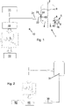
- FIGS 1 and 2 Two embodiments of a device according to the invention are shown in greater detail in FIGS 1 and 2 , as in Figure 3a , Figure 3b and 4 shown.
- the device comprises a receptacle 1 already described above, ie a cutter/compactor or a preconditioning unit.
- the receptacle 1 has a side wall 2 , is cylindrical and has a lower base surface 3 .
- the receptacle 1 can also be of essentially conical design or have a conical or cylindrical wall section.
- the receiving container 1 also comprises a mixing and/or crushing device which is arranged near the bottom 3 .
- the receiving container 1 has a rotating mixing and/or comminuting tool 4 that can be rotated about a vertical axis of rotation 9 as the mixing and/or comminuting device.
- the mixing and/or comminution tool 4 is used to move and mix, and optionally also to heat, comminute and/or soften, the lumpy or particulate material to be treated, with a mixing vortex being formed in the receptacle 1 during operation.
- the material is usually present in lumps or particles, for example as ground material or shredded film.
- Foil shreds of this type have, for example, a thickness of approx. 10 ⁇ m, and individual polymer layers of up to a few mm can already be present in the foil structure.
- the film shreds can be imagined as tending to be flat structures.
- the other two dimensions can range from a few mm to about 30 mm to 500 mm. However, they can also be only a few mm.
- the size is essentially determined by the pre-treatment.
- the regrind can have dimensions from mm to approx. 30 mm to 50 mm. Cubes or ball-like or spherical structures are often formed. However, dust or smaller structures such as microgranules or granules can also be used.
- the materials behave like a fluid and are kept in circulation in the form of a trowel by the mixing and/or comminution tool 4, which has a peripheral speed of approx. 1 m/s to 100 m/s.
- the peripheral speed of the mixing and / or crushing tool 4 is preferably selected so that the lumpy or particulate material radially with a speed of 0.3 to 45 m/s and/or in the vertical direction at a speed of 0.1 to 60 m/s.
- the material is essentially in the range of 0-80% of the height of the receptacle 1.
- the material has a direction of movement on the outside of the receptacle 1, i.e. e.g is. It is essential that the material on the side wall 2, respectively. at a measurement position located there, is exchanged frequently and regularly.
- the material in the receptacle 1 when processing foils or fibers, the material in the receptacle 1 has an average residence time of about 10 to 15 minutes.
- the material circulates radially at approx. 15 m/s. Accordingly, a certain volume segment will pass a measurement position on the side wall 2 between 40 and 200 times. For this reason, both long-term measurements are possible, i.e. it is integrated during the measurement itself, as well as a large number of measurements in a very short time, i.e. statistical methods can then be used in the evaluation to increase the significance of the measurement, which is what follows below will be dealt with in more detail.
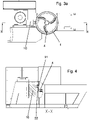
- an opening 8 is formed in a side wall 2 of the receptacle 1 for the discharge, for example in the region of the height of the mixing and/or comminution tool 4 .
- the pretreated plastic material is removed from the interior of the receptacle 1 through this opening 8 . If several mixing and/or comminuting tools 4 are arranged in the receptacle 1, the opening 8 can be arranged in the region of the lowest mixing and/or comminuting tool 4 closest to the bottom.
- a conveyor for example an extruder 5, with a screw 6 rotating in a housing 16, for example plasticizing or agglomerating, takes up the pretreated material emerging from the opening 8 in the exemplary embodiment.
- the housing 16 of the conveyor can, as in Figures 1 and 2 , have a feed opening 80 for the material to be detected by the screw 6 on its end face or in its jacket wall. This intake opening 80 is connected to the opening 8 through which the material emerges from the interior of the receptacle 1 .
- a device according to the invention further comprises a spectroscopic and/or spectrometric measuring device 10 for analyzing the inside of the Receptacle 1 moving lumpy or particulate material or to obtain information about the measured material, in particular of quantitative and / or qualitative parameters of the respective material.
- This is a measuring device 10 which is based on a previously described physical method for examining the energy spectrum of a sample using radiation or waves, for example.
- FIGS Figures 1 to 4 An exemplary embodiment of such a spectroscopic and/or spectrometric measuring device 10 combined with a receptacle 1 is shown in FIGS Figures 1 to 4 shown.
- the measuring device 10 measures at least parts of the lumpy or particulate material moving inside the receiving container 1 inline, ie during the ongoing processing operation.
- the measuring device 10 of a device according to the invention emits a physical effect, such as electromagnetic radiation, sound, electrical voltages or magnetic fields, to excite at least part of the rotating lumpy or particulate material. In the exemplary embodiment shown, this is brought about by an excitation source 11 acting or directed into the interior of the receptacle 1 . Optionally, several such excitation sources 11 can also be provided.
- a physical effect such as electromagnetic radiation, sound, electrical voltages or magnetic fields
- an excitation source 11 emits electromagnetic radiation to excite the material.
- the measuring signals produced as a reaction to the action are detected by the measuring device 10 .
- the measuring device 10 comprises at least one detector 12 for detecting the measuring signals produced as a reaction to the action, in particular characteristic spectra of the electromagnetic radiation scattered on the measured material.
- the detector 12 is a spectroscope.
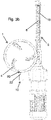
- FIG. 1 and 2 shows the structural connection of a RAMAN spectrometer as a measuring device 10 to a receptacle 1 or a preconditioning unit PCU.
- a RAMAN probe as a measuring head 24 with a lens system 22 is connected to the side of the receptacle 1 at a height below the usual material level or filling level of the particles moving in the receptacle 1 .
- the measuring head 24 are both the light output for that of the Excitation source 11 emitted light, as well as the detection input of the detector 12 for the scattered light from the receptacle 1 combined.
- the beam path of the light emitted by the excitation source 11 in the direction of the interior of the receptacle 1 and the beam path for the scattered light from the receptacle 1 in the direction of the detector 12 can also be realized separately from one another. It is also possible for the detector 12 to be integrated in the measuring head 24 . In this case, the measuring head 24 can be cooled.
- the measuring device 10 can also have a detector 12 for atomic spectroscopy or molecular spectroscopy, in particular a device for Raman spectroscopy, NIR spectroscopy, UV/VIS spectroscopy, fluorescence spectroscopy and /or include absorption spectroscopy.
- the measuring device 10 also includes a processing and control unit 40 in data communication with the measuring device 10, specifically the excitation source 11 and the detector 12.
- the processing and control unit 40 controls on the one hand the measuring device 10 to emit the physical action, in particular to emit electromagnetic radiation, on.
- the processing and control unit 40 controls the measuring device 10 to detect the resulting measuring signals, in particular the characteristic spectra of the scattered electromagnetic radiation, and to keep the measured values determined in this way available.
- the excitation source 11, the detector 12, and the processing and control unit 40 are coupled vibration-free via fiber optic systems and/or light guides 14 to the receptacle 1.
- the excitation source 11, the detector 12, and the processing and control unit 40 can also be arranged at a physical distance from the receptacle 1 or, for example, by means of holding devices on the receptacle 1.
- a laser is used as the excitation source 11, it is advantageous, as in the exemplary embodiment in FIGS Figures 1 and 2 to decouple the detector 12 from the receptacle 1 by means of fiber optics. If fiber optics are not used for the laser or excitation source 11 and detector 12 (free beam system), a vibration-free coupling of the sensors should be achieved by spacing them.
- the fiber optics are selected such that they have a length of less than 100 m, for example less than 30 m to 50 m, preferably less than 15 m, in order to minimize corresponding attenuation of the signals and thus advantageously also lead to cost savings , since lower laser powers are required and the signal-to-noise ratio is improved.
- Optical elements and imaging systems are preferred by appropriate measures such as. Air purge, dry air, N 2 purge, etc. protected from environmental influences such as dust, humidity, temperature, sublimates, etc.
- At least one measurement opening 20 is arranged in the receptacle 1 , through which a measurement of the materials inside the receptacle 1 is made possible. As in the Figures 1 and 2 can be seen in detail, this is located in the side wall 2 of the receptacle 1 in the exemplary embodiment.
- the physical action emitted by the excitation source 11 acts through the measurement opening 20, in the exemplary embodiment this is the emitted electromagnetic radiation, on the material inside the receptacle 1 .
- the measuring opening 20 can have a diameter of 0.5 to 100 mm and can be closed by a window 21 made of material that is permeable to physical influences such as electromagnetic radiation, for example made of sapphire glass.
- a window 21 brings about an effective separation between the sensor system, i.e. the measuring device 10 and the material to be measured.
- the measurement opening 20 is in Figures 1 to 4 arranged in the side wall 2 of the receptacle 1 in the region of the lower third of the height of the receptacle 1.
- the measuring opening 20 can also be in the region of the height of the lowest mixing and/or comminuting tool 4 closest to the floor, in particular slightly above or below it, preferably outside of the narrowest distance between the outermost point of the mixing and/or comminuting tool 4 and the side wall 2 be arranged.
- a preferred mounting position of the measuring device 10 is on the side of the receptacle 1, since the shortest distances to the material to be measured can be realized at this position.
- the distance between the exciting system, ie the excitation source 11, such as a laser or an NIR source, and the measuring system, ie the detector 12 and the material to be measured should preferably be as small as possible.
- the excitation source 11, ie the light sources can advantageously be kept small, while at the same time a good measurement signal is ensured, since light intensity decreases with 1/r 2 , where r indicates the distance between the detector 12 and the material to be measured.
- That position is preferably selected where the density of the material and the pressure on the side wall is highest.
- the material to be measured should pass the sensors of the measuring device 10 with sufficient frequency, the material should pass the focus point 23 of the excitation source 11 .
- a lens or a lens system 22 is provided to focus the electromagnetic radiation of the excitation source 11 on a focal point 23 is in the embodiment, see details in the Figures 1 and 2 .
- the focus point 23 is located on or directly behind the window 21, preferably at a maximum distance of 10 cm behind the window 21.
- the process in the receptacle 1 is carried out in such a way that the level of the material particles or the mixed vortex formed by the movement in the receptacle 1 is maintained such that it is constantly above the excitation source 11 or the light source.
- the material thus covers the window 21 at all times under the operating conditions.
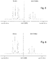
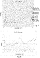
- This covering also serves to shield against extraneous light in the frequency range from 570 nm to 1008 nm, in particular from 785+/-215 nm, in which the measurement frequencies are located. These are 785 + 215 nm for the Stokes range and 785 - 215 nm for the Antistokes range, see figure 5 .
- energy is transferred from the photon (Stokes scattering) to the molecule or from the molecule to the photon (anti-Stokes scattering). Both transitions can be evaluated individually and/or in relation to each other.
- good stability of the measuring signal can advantageously be achieved during the measuring time.
- a range of +/- 245 nm is also possible, see 6 .
- the window in the exemplary embodiment is in Figures 1 to 4 advantageously formed from sapphire glass in order to allow the relevant frequency spectra to pass in the range from 570 nm to 1008 nm, in particular from 785+/-215 nm.
- the window in the exemplary embodiment is in Figures 1 to 4 advantageously formed from sapphire glass in order to allow the relevant frequency spectra to pass in the range from 570 nm to 1008 nm, in particular from 785+/-215 nm.
- at least the range between 931 nm (Stokes) and 678 nm (Anti-Stokes) should be allowed through.
- the surfaces of the window 21 are level and aligned parallel to one another.
- the inner surface of the window 21 facing the receptacle 1 can also be concavely adapted to the radius of the receptacle 1 and the outer surface of the window 21 facing away from the receptacle 1 can be concave parallel to the inner surface.
- the excitation source 11 can be a laser, as in the exemplary embodiment shown, with a wavelength range of 100 to 1400 nm, in the range of infrared, visible and/or UV light, e.g. a wavelength range of 780+/-250 nm
- Other possible lasers that can be used can cover a wavelength range of 532 +/- 215 nm, 638 +/- 215 nm, 820 +/- 215 nm and/or 1064 +/- 215 nm.
- the laser power is, for example, in the range from 15 mW to 5 W, with 100 mW to 500 mW being preferred.
- the use of lasers with a high energy density is advantageously possible since the material is constantly being exchanged and the material to be measured does not change as a result. There may be a particular need for high energy densities, e.g. with very dark-colored polymers.
- the ratio of laser power to integration time is preferably in the range from 5 mW/s to 5000 mW/s, in particular in the range from 15 mW/s to 1000 mW/s.
- the measuring head 24 of the measuring device 10 arranged at the measuring opening 20 or the window 21 with the lens system 22 is advisable to cool the measuring head 24 of the measuring device 10 arranged at the measuring opening 20 or the window 21 with the lens system 22 in order to remain permanently below 90° C., preferably below 60° C.
- Gases or liquids can be used as cooling media, but a Peltier element can also be used.
- the window can also consist of quartz glass in order to allow the relevant frequency spectra in the range from 760 nm to 2500 nm for NIR to pass through.
- Fiber optic systems are to be preferred in order to keep the set-up simple. Fiber optic systems require the least amount of space immediately in front of the window 21. It is possible to couple both measuring devices 10 via a window 21, but also via different windows 21. It has proven useful if the windows 21 are largely at the same height in the circumferential direction. Local proximity is desirable, but not necessary.
- the volume of the material that can be examined is defined by a measuring spot cross-sectional area in the range from 0.1 mm to 5 mm, in particular from 1 mm to 3 mm, and a penetration depth into the material from 0.3 ⁇ m to 30 ⁇ m ⁇ m.
- the penetration depth which leads to good measured values in practice, is in the range of 8 ⁇ m to 15 ⁇ m.
- the measurement spot cross-sectional area is approximately 1 mm to 3 mm, so that a volume of approximately 0.00015 mm 3 can be examined. For this reason, the frequency of the measurement or the frequent movement of the material to be measured past the window 21 is important in order to achieve representative measurement results.
- the processing and control unit 40 derives information about the respectively measured material, in particular quantitative and/or qualitative parameters of the respective material, and makes this available.
- the processing and control unit 40 can spectrometrically and/or spectroscopically analyze the measurement signals produced as a reaction to the action, in particular of characteristic spectra of the electromagnetic radiation scattered on the measured material.
- the lumpy or particulate material moving inside the receptacle 1 is analyzed or measured inline spectroscopically and/or spectrometrically and the measured values determined in this way are used to obtain information about the material measured in each case, in particular quantitative and/or qualitative parameters of the respective material.
- the measurement signals produced as a reaction to the electromagnetic radiation are detected and evaluated, preferably spectrometrically, in the form of characteristic spectra of the electromagnetic radiation scattered on the measured material.
- the evaluation of the measurement results or spectra obtained in this way is carried out by the processing and control unit 40 and is advantageously carried out as follows: Due to the frequent flow of the material particles in a solid to partially softened state at the measuring position or the focus point 23, it is possible to use long measuring times, which enable the use of, for example, lasers with low power of approx. 20-200 mW, while the informative value of the measurement results remain sufficiently accurate.
- the processing and control unit 40 controls the measuring device 10 or the excitation source 11 in such a way that it absorbs the physical effect, for example the electromagnetic radiation emitted by the laser, during a predetermined period of time, for example from less than one second to several seconds or one minute or more.
- the processing and control unit 40 then calculates a single item of common information about the material measured in each case for the respective time period, ie all material particles that have passed the measurement opening 20 or the window 21 in this time period and have been detected by the detector 12 . For example, a single sum spectrum can be created for all these material particles.
- the processing and control unit 40 can control the measuring device 10 or the excitation source 11 in such a way that it repeatedly emits the physical effect, for example the electromagnetic radiation emitted by the laser, at a large number of predetermined times.
- the processing and control unit 40 can then calculate and make available an average value of the information about the material being measured in each case, on the basis of selected or all measured values determined at these times by the measuring device 10, in particular the detector 12, for individual particles. This means that an average is formed from a large number of spectra of individual particles.
- the material flowing past prevents the material to be measured from being influenced by the high energy density of the laser at the focus point 23.
- An unknown material with a higher energy density is methodically excited and the processing and control unit 40 optionally regulates the laser power downwards until the detector 12 is in its linear range. This automated measurement process could not be used in a static measurement process, since the sample or the material would burn or melt.
- a device according to the invention can optionally also include a temperature measuring device 30 which is connected upstream of the processing and control unit 40.
- the material In a normal mode of operation of the receptacle 1, there is in any case a change in temperature of the material: the material is supplied at room temperature or introduced into the receptacle 1 at the top and is then, for example, caused by the movement of the Mixing and / or crushing tools 4 or heated by friction. The material gets hot, softens, but always remains in the form of particles or lumps and does not melt.
- Such an optional temperature measuring device 30 measures the temperature inside the receptacle 1 and/or the temperature of the material and transmits this to the processing and control unit 40.
- the material temperature is recorded, for example, with a temperature sensor that protrudes into the surface layer of the material and used as default for the correction of the spectra.
- the container temperature of the receiving container 1 can also be used as a value.
- Another thermal measuring device for example of an optical nature, can also be attached accordingly to the receptacle 1 in order to record the temperature. In this context, it is particularly advantageous to install the temperature measuring device 30 in close proximity to the window 21 covering the measuring opening 20 or to the measuring head 24 of the measuring device.
- the temperature measuring device 30 can be arranged in the receptacle 1 e.g. at the same height, in particular at the same position, as the at least one measuring opening 20.
- the processing and control unit 40 uses the measured values determined by the one temperature measuring device 30 for a correction of the temperature influence on the information determined for the respectively measured material, in particular the temperature-dependent characteristic spectra of the electromagnetic radiation scattered on the measured material, and keeps the information corrected in this way , in particular spectra, are available.
- the temperature information obtained in this way is included in the evaluation and serves as an indication for a temperature correction of the spectra.
- the material temperature of the material in the receptacle 1 is measured and sent to the processing and control unit 40 .
- the measured actual temperature is used to correct the spectra, for example to a reference temperature, in order to enable a simple comparison with stored reference spectra.
- a temperature-related shift, ie a shift, of the spectra to higher intensities is corrected.
- the processing and control unit 40 can include a memory in which reference information, e.g. quantitative and/or qualitative reference parameters or reference spectra, is stored. The processing and control unit 40 can then compare the information determined for the respectively measured material, such as spectra, with the reference information, e.g. reference spectra, and determine the deviation from the reference information or reference spectra. This determined deviation can then be forwarded to a process control unit and/or a display unit, for example.
- reference information e.g. quantitative and/or qualitative reference parameters or reference spectra
- the processing and control unit 40 can optionally also interact with a process control unit 50 or be in data communication.
- a process control unit can, for example, use data transmitted by the processing and control unit 40, i.e. information about the material being measured in each case, such as quantitative and/or qualitative parameters of the material in question, for monitoring and/or controlling the process control in the receptacle 1 and/or of the subsequent process chain.
- thermoplastic materials especially thermoplastic materials
- different polymers with different viscosities and filling levels of fillers such as CaCO 3
- the non-woven part of the hygiene articles mostly consists of unfilled PP and the film consists of LD-PE filled with CaCO 3 .
- the punching residues but also film residues that occur during production therefore have a different polymer content and a different degree of filling.
- the detector 12 or the spectroscope registered clear spectra.
- the spectra recorded by detector 12 are in 7 shown.
- the spectra indicate mixtures of PE and varying percentages of CaCO 3 (1%, 2%, 5%, 10%, 15%, 17.5%, 20% CaCOs).
- the recorded spectra are evaluated by the processing and control unit 40 with regard to the proportion of CaCO 3 and the proportion of CaCO 3 is made available by the processing and control unit 40 as a percentage of the total material.
- a control signal can thus be derived from a process control unit 50 connected to the processing and control unit 40, such as a dosing unit, on the basis of which the supply of CaCO 3 in powder form or as a masterbatch is appropriately adapted. With a higher proportion in the input material, the dosing quantity can be reduced accordingly and increased with a lower proportion in the input material. A uniform proportion of CaCO 3 is then advantageously present in the end product produced.
- a CaCO 3 content of approx. 15% - 25% is usually provided for injection molded products, depending on the application, whereby the deviation may only be +/- 1% in each case.
- a second application example of a method according to the invention or a device according to the invention is described below:
- the different polymer streams are separated and cleaned as well as possible by sorting and washing processes.
- the subsequent thermal forming process (extrusion)
- both homogenization and melt filtration are carried out.
- the regrind produced from this must be of a certain quality: For example, the proportion of PP used in the production of blown film from LDPE should not exceed a certain percentage, since the desired mechanical properties may not subsequently be achieved can be achieved or the weldability can no longer be guaranteed.
- An INTAREMA 80TVEplus comprising a measuring device 10 with a detector 12 for RAMAN spectroscopy and a receiving container 1, ie a cutter/compactor or a preconditioning unit, was used to carry out the test.
- the suitability of a measuring device based on RAMAN spectroscopy was demonstrated by adding PE film to a pure PP film in the receptacle 1 .
- two film rolls, one PP roll and one LDPe roll, with a known film width and film thickness were each fed to the receiving container 1 via a separate feed value.
- the percentage distribution was calculated from the basis weight and confirmed by random testing on the granules produced. Table 2 summarizes the experimental data.
- Table 2 Test data second application example material machine PCU temperature PCU performance speed tool laser intensity integration time Number of measurements Measurement time per spectrum [°C] [kW] [rpm] [mW] [n] [n] PE/PP INTAREMA 1108 TVEplus 100 40-41 750 150 4 10 40
- the spectra recorded by detector 12 are in 9 shown.
- the spectra show mixtures of PP and PE with varying percentages (100%, 90%, 70%, 50%, 25%, 10% 0% PP).
- the recorded spectra are evaluated by the processing and control unit 40 and the proportion of PP is made available by the processing and control unit 40 as a percentage of the total material, see FIG 10 .
- PE/PA composites are used as packaging film for food. It is a multi-layer structure, in the middle of which is the PA film, which is used as e.g.
- PE polyethylene
- PA polyamide
- An INTAREMA 1108 TE comprising a measuring device 10 with a detector 12 for RAMAN spectroscopy and a receiving container 1, ie a cutter/compactor or a preconditioning unit, was used to carry out the test.
- a continuously measuring measuring device 10 based on RAMAN spectroscopy was demonstrated by adding the PE/PA edge strips and pieces of film to the receptacle 1 .
- the corresponding polymer proportions were checked using laboratory measuring devices of the proportions previously determined inline. Table 3 summarizes the experimental data.
- Table 3 Test data third application example material machine PCU temperature PCU performance speed tool laser intensity integration time Number of measurements Measurement time per spectrum [°C] [kW] [rpm] [mW] [n] [n] PE/PA INTAREMA 1108TE 107 48-54 750 350 3 10 30
- the spectra recorded by the detector 12 are evaluated by the processing and control unit 40 and the proportion of PA to PE is displayed by the processing and control unit 40, see in this regard 11 .
- the above-described device according to the invention and the above-described method according to the invention, using spectroscopic and/or spectrometric measuring devices 10, enable effective inline process analysis, monitoring and, if necessary, control in systems for preparing, processing and/or recycling materials ,
- a receptacle 1, ie a cutter compressor or a preconditioning unit PCU allows.
- the information/data transmitted by the evaluation unit can also be used in the subsequent process chain, such as when adding fillers, discharging finished granules, but also when feeding other polymers, e.g. into the receiving container 1, i.e. the cutter compactor or the preconditioning unit PCU, are used.
- a second aspect of the invention relates to a method according to or according to the first aspect, characterized in that at least parts of the lumpy or particulate material located inside the receptacle 1 and rotating there is excited by a physical effect, in particular by electromagnetic radiation, and the measurement signals arising as a reaction to the action, in particular characteristic spectra of the electromagnetic radiation scattered on the measured material, are detected, preferably spectrometrically.
- a third aspect of the invention relates to a method according to the first or second aspect, characterized in that the spectroscopic and/or spectrometric measurement is carried out using atomic spectroscopy or molecular spectroscopy, in particular using Raman spectroscopy, NIR spectroscopy, UV/VIS spectroscopy, fluorescence spectroscopy and/or absorption spectroscopy.
- a fourth aspect of the invention relates to a method according to one of aspects one to three, characterized in that light in the range of infrared, visible and/or UV light is used for excitation, in particular in the range from 100 to 1400 nm, preferably from 500 to 1000 nm, and/or that a laser is used for excitation, in particular with a wavelength range from 100 nm to 1400 nm and/or with a power in the range from 15 mW to 5 W, preferably from 100 to 500 mW.
- a fifth aspect of the invention relates to a method according to one of aspects one to four, characterized in that light is detected and analyzed in order to determine specific quantitative and/or qualitative parameters of the material, in particular of the thermoplastic material, or changes in these parameters during the process to detect inline and to use for monitoring and / or control of the process and / or to use these parameters to control the process control in the receptacle 1.
- a sixth aspect of the invention relates to a method according to one of aspects one to five, characterized in that the electromagnetic radiation exciting the material is focused on a focal point 23 which is inside the receptacle 1 on or immediately behind the container wall, preferably at a distance of a maximum of 10 cm behind the container wall.
- a seventh aspect of the invention relates to a method according to one of the first to sixth aspects, characterized in that the physical effect, in particular the electromagnetic radiation, causes a measuring spot cross-sectional area of 0.1 mm to 5 mm, in particular from 1 mm to 3 mm, and a penetration depth into the material of 0.3 ⁇ m to 30 ⁇ m, in particular from 8 ⁇ m to 15 ⁇ m, defined volume area is excited.
- a ninth aspect of the invention relates to a method according to one of the first to eighth aspects, characterized in that the lumpy or particulate material in the outer region of the receptacle 1, in particular on the side wall 2 of the receptacle 1, has a direction of movement in the circumferential direction and/or a has a predominantly upward direction of movement.
- a tenth aspect of the invention relates to a method according to one of aspects one to nine, characterized in that the lumpy or particulate material radially at a speed of 0.3 m / s to 45 m / s and / or in the vertical direction with a Speed of 0.1 m / s to 60 m / s circulates, so that the lumpy or particulate material in the outer region of the receptacle 1, in particular on the side wall 2 of the receptacle 1, is replaced frequently and regularly.
- a thirteenth aspect of the invention relates to a method according to one of aspects one to twelve, characterized in that the temperature inside the receptacle 1 and/or the temperature of the material is measured and the temperature information is included in the evaluation and as an indication for the correction the information about the respectively measured material, in particular the quantitative and/or qualitative parameters of the respective material, is used and/or the material temperature is recorded and used as a specification for the correction of the spectra.
- a fifteenth aspect of the invention relates to a device for carrying out a method according to one of the first to fourteen aspects, with at least one receiving container 1, in particular a cutter/compactor and/or a preconditioning unit PCU, with a mixing and/or crushing device for the material and with a spectroscopic and/or spectrometric measuring device 10 for analyzing the lumpy or particulate material or to obtain information about the measured material, in particular of quantitative and / or qualitative parameters of the respective material.
- a seventeenth aspect of the invention relates to a device according to aspect fifteen or sixteen, characterized in that the receptacle 1 has a side wall 2 and is essentially conical or cylindrical or has a conical or cylindrical wall section, and optionally also a lower floor surface 3 .
- An eighteenth aspect of the invention relates to a device according to one of the fifteenth to seventeenth aspects, characterized in that in the receptacle 1 as a mixing and/or comminuting device, at least one rotating mixing and/or comminuting tool 4, in particular rotatable about a vertical axis of rotation 9, for Movement and mixing, and optionally also for heating, comminution and/or softening, of the lumpy or particulate material to be treated is arranged, with a vortex and/or a mixing vortex being able to be formed in the receptacle 1 during operation.
- a nineteenth aspect of the invention relates to a device according to one of aspects fifteen to eighteen, characterized in that the peripheral speed of the mixing and / or crushing tool 4 is selected such that the lumpy or particulate material radially at a speed of 0.3 to 45 m/s and/or in the vertical direction at a speed of 0.1 to 60 m/s.
- a twentieth aspect of the invention relates to a device according to one of the fifteenth to nineteenth aspects, characterized in that in the receptacle 1, in particular in a side wall 2 of the receptacle 1, in particular in the area of the height of the lowest mixing and/or crushing tool closest to the floor 4, an opening 8 is formed, through which the pretreated plastic material can be discharged from the interior of the receptacle 1, and that at least one conveyor, in particular an extruder 5, with at least one rotating, in particular plasticizing or agglomerating, screw 6 in a housing 16, for receiving the pretreated material emerging from the opening 8, it being provided in particular that the housing 16 has a feed opening 80 located on its end face or in its jacket wall for the material to be picked up by the screw 6, and the feed opening 80 with the Opening 8 is connected.
- a twenty-second aspect of the invention relates to a device according to one of the fifteen to twenty-first aspects, characterized in that the processing and control unit 40 for the spectrometric and/or spectroscopic analysis of the measurement signals produced as a reaction to the action, in particular of characteristic spectra of the material being measured scattered electromagnetic radiation.
- a twenty-third aspect of the invention relates to a device according to one of the fifteen to twenty-second aspects, characterized in that the excitation source 11 and/or the detector 12 and/or the processing and control unit 40 is physically spaced from the receptacle 1 or is vibration-free on the receptacle 1, in particular via fiber optic systems and/or light guides 14, are coupled.
- a twenty-fourth aspect of the invention relates to a device according to one of aspects fifteen to twenty-three, characterized in that the measuring device 10 is a device, in particular a detector 12, for atomic spectroscopy or molecular spectroscopy, in particular for Raman spectroscopy, NIR spectroscopy, UV/VIS spectroscopy, fluorescence spectroscopy and/or absorption spectroscopy.
- the measuring device 10 is a device, in particular a detector 12, for atomic spectroscopy or molecular spectroscopy, in particular for Raman spectroscopy, NIR spectroscopy, UV/VIS spectroscopy, fluorescence spectroscopy and/or absorption spectroscopy.
- a twenty-fifth aspect of the invention relates to a device according to one of the twenty-first to twenty-fourth aspects, characterized in that the excitation source 11 is designed to emit light in the infrared, visible and/or UV light range, in particular in the range from 100 to 1400 nm, preferably from 500 to 1000 nm.
- a twenty-sixth aspect of the invention relates to a device according to one of aspects twenty-first to twenty-fifth, characterized in that the excitation source 11 is a laser, in particular with a wavelength range from 100 nm to 1400 nm and/or a power in the range from 15 mW to 5 W , preferably from 100 mW to 500 mW.
- the excitation source 11 is a laser, in particular with a wavelength range from 100 nm to 1400 nm and/or a power in the range from 15 mW to 5 W , preferably from 100 mW to 500 mW.
- a twenty-seventh aspect of the invention relates to a device according to one of aspects fifteen to twenty-six, characterized in that at least one measurement opening 20 is provided in the receptacle 1, in particular in the side wall 2 of the receptacle 1, the measurement opening 20 being such is designed such that the physical effect emitted by the excitation source 11, in particular the emitted electromagnetic radiation, acts on the material in the receptacle 1 and scattered light from the receptacle 1 can be detected.
- a twenty-eighth aspect of the invention relates to a device according to aspect twenty-seventh, characterized in that the measurement opening 20 has a diameter of 0.5 to 100 mm.
- a twenty-ninth aspect of the invention relates to a device according to one of the twenty-seventh or twenty-eighth aspects, characterized in that the measuring opening 20 is closed by a window 21 made of material, for example sapphire glass, which is transparent, in particular for electromagnetic radiation.
- a thirtieth aspect of the invention relates to a device according to aspect twenty-nine, characterized in that the window 21 has a thickness of 1 to 100 mm.
- a thirty-first aspect of the invention relates to a device according to aspect twenty-nine or thirty, characterized in that the surfaces of the window 21 are plane and aligned parallel to one another or that the inner surface of the window 21 facing the receptacle 1 is concavely adapted to the radius of the receptacle 1 and the outer surface of the window 21 facing away from the receptacle 1 is concave parallel to the inner surface.
- a thirty-fourth aspect of the invention relates to a device according to one of the fifteen to thirty-third aspects, characterized in that the volume area that can be excited by the physical effect, in particular the electromagnetic radiation, has a measuring spot cross-sectional area of 0.1 mm to 5 mm, in particular from 1 mm to 3 mm, and a penetration depth into the material of 0.3 ⁇ m to 30 ⁇ m, in particular from 8 ⁇ m to 15 ⁇ m.
- a thirty-fifth aspect of the invention relates to a device according to one of aspects fifteen to thirty-four, characterized in that a lens or a lens system 22 is provided for focusing the electromagnetic radiation of the excitation source 11 onto a focus point 23, with the focus point 23 in particular at or immediately behind the window 21, preferably at a maximum distance of 10 cm behind the window 21 is formed.
- a thirty-sixth aspect of the invention relates to a device according to one of the fifteen to thirty-fifth aspects, characterized in that the processing and control unit 40 interacts with a process control unit 50 and is in data communication, with the process control unit 50 being designed to data transmitted by the processing and control unit 40, in particular information about the respectively measured material, preferably quantitative and/or qualitative parameters of the respective material, for monitoring and/or controlling the process control in the receptacle 1 and/or the subsequent process chain.
- a thirty-eighth aspect of the invention relates to a device according to one of aspects fifteen to thirty-seventh, characterized in that at least one temperature measuring device 30 is provided upstream of the processing and control unit 40, with the temperature measuring device 30 being designed to measure the temperature inside the receptacle 1 and /or measure the temperature of the material and transmit it to the processing and control unit 40, and processing and control unit 40 is designed to use the measured values determined by the at least one temperature measuring device 30 to correct the temperature influence on the information determined for the material being measured, in particular the temperature-dependent characteristic spectra of the electromagnetic radiation scattered on the material being measured, and to keep the information corrected in this way, in particular spectra, available.
- a thirty-ninth aspect of the invention relates to a device according to aspect thirty-eight, characterized in that the temperature measuring device 30 in the receptacle 1 is arranged at the same height, in particular at the same position, as the at least one measuring opening 20 .
Landscapes
- Health & Medical Sciences (AREA)
- Chemical & Material Sciences (AREA)
- Physics & Mathematics (AREA)
- Life Sciences & Earth Sciences (AREA)
- Engineering & Computer Science (AREA)
- Pathology (AREA)
- Analytical Chemistry (AREA)
- Biochemistry (AREA)
- General Health & Medical Sciences (AREA)
- General Physics & Mathematics (AREA)
- Immunology (AREA)
- Environmental & Geological Engineering (AREA)
- Mechanical Engineering (AREA)
- Spectroscopy & Molecular Physics (AREA)
- Medicinal Chemistry (AREA)
- Nuclear Medicine, Radiotherapy & Molecular Imaging (AREA)
- Food Science & Technology (AREA)
- Polymers & Plastics (AREA)
- Organic Chemistry (AREA)
- Chemical Kinetics & Catalysis (AREA)
- Sustainable Development (AREA)
- Investigating Or Analysing Materials By Optical Means (AREA)
- Investigating, Analyzing Materials By Fluorescence Or Luminescence (AREA)
- Processing And Handling Of Plastics And Other Materials For Molding In General (AREA)
- Separation, Recovery Or Treatment Of Waste Materials Containing Plastics (AREA)
- Processing Of Solid Wastes (AREA)
Applications Claiming Priority (3)
| Application Number | Priority Date | Filing Date | Title |
|---|---|---|---|
| AT507382018 | 2018-08-29 | ||
| EP19762701.1A EP3843966B1 (fr) | 2018-08-29 | 2019-08-28 | Procédé et dispositif pour traiter, travailler et/ou recycler des matériaux thermoplastiques |
| PCT/AT2019/060278 WO2020041813A1 (fr) | 2018-08-29 | 2019-08-28 | Procédé et dispositif destiné à préparer, à traiter et/ou à recycler des matériaux |
Related Parent Applications (2)
| Application Number | Title | Priority Date | Filing Date |
|---|---|---|---|
| EP19762701.1A Division EP3843966B1 (fr) | 2018-08-29 | 2019-08-28 | Procédé et dispositif pour traiter, travailler et/ou recycler des matériaux thermoplastiques |
| EP19762701.1A Division-Into EP3843966B1 (fr) | 2018-08-29 | 2019-08-28 | Procédé et dispositif pour traiter, travailler et/ou recycler des matériaux thermoplastiques |
Publications (1)
| Publication Number | Publication Date |
|---|---|
| EP4119320A1 true EP4119320A1 (fr) | 2023-01-18 |
Family
ID=67847562
Family Applications (2)
| Application Number | Title | Priority Date | Filing Date |
|---|---|---|---|
| EP19762701.1A Active EP3843966B1 (fr) | 2018-08-29 | 2019-08-28 | Procédé et dispositif pour traiter, travailler et/ou recycler des matériaux thermoplastiques |
| EP22192112.5A Pending EP4119320A1 (fr) | 2018-08-29 | 2019-08-28 | Procédé et dispositif de préparation, de traitement et/ou de recyclage de matériaux |
Family Applications Before (1)
| Application Number | Title | Priority Date | Filing Date |
|---|---|---|---|
| EP19762701.1A Active EP3843966B1 (fr) | 2018-08-29 | 2019-08-28 | Procédé et dispositif pour traiter, travailler et/ou recycler des matériaux thermoplastiques |
Country Status (17)
| Country | Link |
|---|---|
| US (1) | US20210197421A1 (fr) |
| EP (2) | EP3843966B1 (fr) |
| JP (1) | JP7369765B2 (fr) |
| KR (1) | KR20210047929A (fr) |
| CN (1) | CN112912220B (fr) |
| AU (1) | AU2019329926A1 (fr) |
| BR (1) | BR112021003619B1 (fr) |
| CA (1) | CA3110716A1 (fr) |
| DK (1) | DK3843966T3 (fr) |
| ES (1) | ES2932378T3 (fr) |
| HU (1) | HUE060862T2 (fr) |
| MX (1) | MX2021002331A (fr) |
| PL (1) | PL3843966T3 (fr) |
| PT (1) | PT3843966T (fr) |
| SI (1) | SI3843966T1 (fr) |
| WO (1) | WO2020041813A1 (fr) |
| ZA (1) | ZA202101522B (fr) |
Families Citing this family (4)
| Publication number | Priority date | Publication date | Assignee | Title |
|---|---|---|---|---|
| US11878327B2 (en) | 2019-03-13 | 2024-01-23 | Digimarc Corporation | Methods and arrangements for sorting items, useful in recycling |
| CN113499707A (zh) * | 2021-07-13 | 2021-10-15 | 上海爱尔企业发展股份有限公司 | 一种纺织助剂配料预加工的锥形混合机入料设备 |
| CN114558881B (zh) * | 2022-03-10 | 2022-12-09 | 广东省车汇莱再生物资回收有限公司 | 一种基于智能化的新能源报废汽车资源化回收系统 |
| CN115709212B (zh) * | 2022-11-21 | 2024-09-17 | 海南大学 | 一种用于研究塑料生物降解的实验装置 |
Citations (7)
| Publication number | Priority date | Publication date | Assignee | Title |
|---|---|---|---|---|
| EP0123771A1 (fr) | 1983-04-27 | 1984-11-07 | EREMA Engineering Recycling Maschinen und Anlagen Gesellschaft m.b.H. | Dispositif pour préparer un mélange de matière thermoplastique |
| EP1264170A2 (fr) * | 2000-03-10 | 2002-12-11 | Textron Systems Corporation | Sondes optiques et procedes d'analyse spectrale |
| EP2525953B1 (fr) | 2010-01-22 | 2013-12-18 | EREMA Engineering Recycling Maschinen und Anlagen Gesellschaft m.b.H. | Procédé et dispositif pour le traitement et la décontamination |
| EP2689908A1 (fr) * | 2010-04-14 | 2014-01-29 | EREMA Engineering Recycling Maschinen und Anlagen Gesellschaft m.b.H. | Dispositif et procédé de préparation de matière synthétique |
| EP3128303A2 (fr) * | 2015-08-05 | 2017-02-08 | Viavi Solutions Inc. | Surveillance de processus spectrale in situ |
| WO2017051424A1 (fr) * | 2015-09-25 | 2017-03-30 | Verifood Ltd. | Mélangeur spectral |
| EP3537119A1 (fr) * | 2018-03-06 | 2019-09-11 | Vorwerk & Co. Interholding GmbH | Analyse d'un aliment |
Family Cites Families (9)
| Publication number | Priority date | Publication date | Assignee | Title |
|---|---|---|---|---|
| JPS62250333A (ja) * | 1986-04-24 | 1987-10-31 | Toonichi Consultant:Kk | 懸濁液光学測定装置 |
| DE3922902A1 (de) * | 1989-07-12 | 1991-01-17 | Hoechst Ag | Verfahren zur herstellung einer farbigen kunststoff-formmasse |
| JPH0732363A (ja) * | 1993-07-16 | 1995-02-03 | Matsui Mfg Co | 粉粒体の混合装置とこの混合装置を備えた樹脂成形機 |
| JPH10185817A (ja) * | 1996-12-26 | 1998-07-14 | Mitsubishi Heavy Ind Ltd | レーザを用いた組成成分計測方法 |
| DE10024309A1 (de) * | 2000-05-17 | 2001-11-29 | Der Gruene Punkt Duales Syst | Verfahren und Vorrichtung zur trockenen Auftrennung von Sammelmüll mit Verpackungsabfällen |
| JP4579466B2 (ja) * | 2000-08-25 | 2010-11-10 | テクノポリマー株式会社 | 樹脂リサイクルシステム |
| JP5207391B2 (ja) * | 2009-03-09 | 2013-06-12 | シャープ株式会社 | プラスチック部材の製造方法 |
| AT512209B1 (de) * | 2011-10-14 | 2015-02-15 | Erema | Vorrichtung zum aufbereiten von kunststoffmaterial |
| CN203427220U (zh) * | 2013-08-21 | 2014-02-12 | 武汉力富特液压科技有限公司 | 新型废塑料混合分选机 |
-
2019
- 2019-08-28 MX MX2021002331A patent/MX2021002331A/es unknown
- 2019-08-28 AU AU2019329926A patent/AU2019329926A1/en active Pending
- 2019-08-28 PT PT197627011T patent/PT3843966T/pt unknown
- 2019-08-28 US US17/271,493 patent/US20210197421A1/en active Pending
- 2019-08-28 PL PL19762701.1T patent/PL3843966T3/pl unknown
- 2019-08-28 EP EP19762701.1A patent/EP3843966B1/fr active Active
- 2019-08-28 DK DK19762701.1T patent/DK3843966T3/da active
- 2019-08-28 EP EP22192112.5A patent/EP4119320A1/fr active Pending
- 2019-08-28 KR KR1020217008832A patent/KR20210047929A/ko active Search and Examination
- 2019-08-28 BR BR112021003619-9A patent/BR112021003619B1/pt active IP Right Grant
- 2019-08-28 ES ES19762701T patent/ES2932378T3/es active Active
- 2019-08-28 SI SI201930409T patent/SI3843966T1/sl unknown
- 2019-08-28 CA CA3110716A patent/CA3110716A1/fr active Pending
- 2019-08-28 JP JP2021510399A patent/JP7369765B2/ja active Active
- 2019-08-28 WO PCT/AT2019/060278 patent/WO2020041813A1/fr active Search and Examination
- 2019-08-28 HU HUE19762701A patent/HUE060862T2/hu unknown
- 2019-08-28 CN CN201980071366.9A patent/CN112912220B/zh active Active
-
2021
- 2021-03-05 ZA ZA2021/01522A patent/ZA202101522B/en unknown
Patent Citations (8)
| Publication number | Priority date | Publication date | Assignee | Title |
|---|---|---|---|---|
| EP0123771A1 (fr) | 1983-04-27 | 1984-11-07 | EREMA Engineering Recycling Maschinen und Anlagen Gesellschaft m.b.H. | Dispositif pour préparer un mélange de matière thermoplastique |
| EP1264170A2 (fr) * | 2000-03-10 | 2002-12-11 | Textron Systems Corporation | Sondes optiques et procedes d'analyse spectrale |
| EP2525953B1 (fr) | 2010-01-22 | 2013-12-18 | EREMA Engineering Recycling Maschinen und Anlagen Gesellschaft m.b.H. | Procédé et dispositif pour le traitement et la décontamination |
| EP2689908A1 (fr) * | 2010-04-14 | 2014-01-29 | EREMA Engineering Recycling Maschinen und Anlagen Gesellschaft m.b.H. | Dispositif et procédé de préparation de matière synthétique |
| EP2689908B1 (fr) | 2010-04-14 | 2016-02-10 | EREMA Engineering Recycling Maschinen und Anlagen Gesellschaft m.b.H. | Dispositif et procédé de préparation de matière synthétique |
| EP3128303A2 (fr) * | 2015-08-05 | 2017-02-08 | Viavi Solutions Inc. | Surveillance de processus spectrale in situ |
| WO2017051424A1 (fr) * | 2015-09-25 | 2017-03-30 | Verifood Ltd. | Mélangeur spectral |
| EP3537119A1 (fr) * | 2018-03-06 | 2019-09-11 | Vorwerk & Co. Interholding GmbH | Analyse d'un aliment |
Also Published As
| Publication number | Publication date |
|---|---|
| ES2932378T3 (es) | 2023-01-18 |
| PL3843966T3 (pl) | 2023-03-20 |
| BR112021003619B1 (pt) | 2024-04-30 |
| SI3843966T1 (sl) | 2023-02-28 |
| KR20210047929A (ko) | 2021-04-30 |
| CN112912220B (zh) | 2023-06-27 |
| MX2021002331A (es) | 2021-08-11 |
| DK3843966T3 (da) | 2023-01-09 |
| HUE060862T2 (hu) | 2023-04-28 |
| BR112021003619A2 (pt) | 2021-05-18 |
| EP3843966B1 (fr) | 2022-10-05 |
| JP2022501578A (ja) | 2022-01-06 |
| EP3843966A1 (fr) | 2021-07-07 |
| ZA202101522B (en) | 2022-06-29 |
| CN112912220A (zh) | 2021-06-04 |
| AU2019329926A1 (en) | 2021-04-15 |
| WO2020041813A1 (fr) | 2020-03-05 |
| US20210197421A1 (en) | 2021-07-01 |
| PT3843966T (pt) | 2022-12-06 |
| JP7369765B2 (ja) | 2023-10-26 |
| CA3110716A1 (fr) | 2020-03-05 |
Similar Documents
| Publication | Publication Date | Title |
|---|---|---|
| EP3843966B1 (fr) | Procédé et dispositif pour traiter, travailler et/ou recycler des matériaux thermoplastiques | |
| US6586504B1 (en) | Wood and plastic composite material and methods for making same | |
| EP2110224B1 (fr) | Procédé et dispositif de fabrication de récipients en plastique avec surveillance de l'absorption par infrarouges | |
| EP2177342B1 (fr) | Dispositif de transport à extrusion | |
| EP3268725B1 (fr) | Procédé et dispositif permettant l'identification de matières plastiques et de leurs additifs | |
| EP3494383A1 (fr) | Dispositif d'identification de substances | |
| EP2756029B1 (fr) | Feuille colorée en polymère, dispositif et procédé de fabrication de feuille | |
| WO2010081629A1 (fr) | Essai rapide d'abrasion pour granulés | |
| DE102008019176A1 (de) | Verfahren und Vorrichtung zur Herstellung von Kunststoffbehältnissen mit Infrarot-Absorptionsüberwachung | |
| DE102008039375A1 (de) | Verfahren und Vorrichtung zur Herstellung von Kunststoffbehältnissen mit Infrarot-Absorptionsüberwachung | |
| CN103946315A (zh) | 复合产品、其制造方法及其应用,材料组分及最终产品 | |
| EP3322983B1 (fr) | Procédé pour fournir un combustible de remplacement et procédé d'analyse finale d'un combustible de remplacement | |
| RU2805333C2 (ru) | Способ и устройство для подготовки, обработки и/или рециклинга материалов | |
| DE102011053478B4 (de) | Verfahren zur Bestimmung einer Zusammensetzung einer plastifizierten Elastomermischung auf der Basis wenigstens eines polaren oder unpolaren Kautschuks | |
| DE102005036643A1 (de) | Verfahren und Vorrichtung zur Ermittlung des Reifezustandes von Duroplast-Zusammensetzungen | |
| AT504893B1 (de) | Verfahren zum bestimmen der zusammensetzung von faserstoffgemischen und/oder formteilen | |
| CN203941107U (zh) | 一种聚合物熔体性质的拉曼光谱在线测量装置 | |
| EP2376889A2 (fr) | Essai rapide pour déterminer l'influence d'un rayonnement sur l'abrasion de granulés | |
| DE10318893A1 (de) | System und Verfahren zur Bestimmung und Verteilung der Inhaltsstoffe in Verpackungsmitteln | |
| WO2013091623A1 (fr) | Procédé de vérification du respect d'une concentration théorique prescrite d'un premier composant dans un article en matériau thermoplastique, et premier composant d'un matériau thermoplastique | |
| DE10318892A1 (de) | System und Verfahren zur fortlaufenden Referenzierung von Reflektionsmessungen zur Kontrolle von flüssigen oder rieselfähigen Gütern | |
| DE19932746B4 (de) | Verfahren und Vorrichtung zur spektroskopischen Untersuchung von plastifizierten Extrudaten | |
| WO2009040291A1 (fr) | Procédé et dispositif de mesure de propriétés chromatiques de granulats de matière plastique | |
| Becker et al. | Near infrared spectroscopy as a tool for in-line control of process and material properties of PLA biopolymer | |
| DE102018204831A1 (de) | Herstellung einer faserverstärkten Kautschukmischung |
Legal Events
| Date | Code | Title | Description |
|---|---|---|---|
| PUAI | Public reference made under article 153(3) epc to a published international application that has entered the european phase |
Free format text: ORIGINAL CODE: 0009012 |
|
| STAA | Information on the status of an ep patent application or granted ep patent |
Free format text: STATUS: THE APPLICATION HAS BEEN PUBLISHED |
|
| AC | Divisional application: reference to earlier application |
Ref document number: 3843966 Country of ref document: EP Kind code of ref document: P |
|
| AK | Designated contracting states |
Kind code of ref document: A1 Designated state(s): AL AT BE BG CH CY CZ DE DK EE ES FI FR GB GR HR HU IE IS IT LI LT LU LV MC MK MT NL NO PL PT RO RS SE SI SK SM TR |
|
| STAA | Information on the status of an ep patent application or granted ep patent |
Free format text: STATUS: REQUEST FOR EXAMINATION WAS MADE |
|
| 17P | Request for examination filed |
Effective date: 20230718 |
|
| RBV | Designated contracting states (corrected) |
Designated state(s): AL AT BE BG CH CY CZ DE DK EE ES FI FR GB GR HR HU IE IS IT LI LT LU LV MC MK MT NL NO PL PT RO RS SE SI SK SM TR |
|
| GRAP | Despatch of communication of intention to grant a patent |
Free format text: ORIGINAL CODE: EPIDOSNIGR1 |
|
| STAA | Information on the status of an ep patent application or granted ep patent |
Free format text: STATUS: GRANT OF PATENT IS INTENDED |
|
| RIC1 | Information provided on ipc code assigned before grant |
Ipc: G01N 21/84 20060101ALN20240607BHEP Ipc: G01N 21/33 20060101ALN20240607BHEP Ipc: G01N 21/359 20140101ALN20240607BHEP Ipc: G01N 33/44 20060101ALI20240607BHEP Ipc: G01N 21/85 20060101ALI20240607BHEP Ipc: G01N 21/65 20060101ALI20240607BHEP Ipc: G01N 21/64 20060101ALI20240607BHEP Ipc: G01N 21/51 20060101ALI20240607BHEP Ipc: G01N 21/31 20060101ALI20240607BHEP Ipc: B29B 17/04 20060101ALI20240607BHEP Ipc: B29B 17/00 20060101AFI20240607BHEP |
|
| INTG | Intention to grant announced |
Effective date: 20240624 |