EP4119086A1 - Mobiler träger und lagersystem für ein medizinprodukt - Google Patents
Mobiler träger und lagersystem für ein medizinprodukt Download PDFInfo
- Publication number
- EP4119086A1 EP4119086A1 EP22194515.7A EP22194515A EP4119086A1 EP 4119086 A1 EP4119086 A1 EP 4119086A1 EP 22194515 A EP22194515 A EP 22194515A EP 4119086 A1 EP4119086 A1 EP 4119086A1
- Authority
- EP
- European Patent Office
- Prior art keywords
- arm
- roller shaft
- mobile support
- rail
- carriage
- Prior art date
- Legal status (The legal status is an assumption and is not a legal conclusion. Google has not performed a legal analysis and makes no representation as to the accuracy of the status listed.)
- Granted
Links
Images


Classifications
-
- A—HUMAN NECESSITIES
- A61—MEDICAL OR VETERINARY SCIENCE; HYGIENE
- A61B—DIAGNOSIS; SURGERY; IDENTIFICATION
- A61B50/00—Containers, covers, furniture or holders specially adapted for surgical or diagnostic appliances or instruments, e.g. sterile covers
- A61B50/10—Furniture specially adapted for surgical or diagnostic appliances or instruments
- A61B50/13—Trolleys, e.g. carts
-
- A—HUMAN NECESSITIES
- A61—MEDICAL OR VETERINARY SCIENCE; HYGIENE
- A61B—DIAGNOSIS; SURGERY; IDENTIFICATION
- A61B90/00—Instruments, implements or accessories specially adapted for surgery or diagnosis and not covered by any of the groups A61B1/00 - A61B50/00, e.g. for luxation treatment or for protecting wound edges
- A61B90/50—Supports for surgical instruments, e.g. articulated arms
- A61B90/57—Accessory clamps
-
- A—HUMAN NECESSITIES
- A61—MEDICAL OR VETERINARY SCIENCE; HYGIENE
- A61G—TRANSPORT, PERSONAL CONVEYANCES, OR ACCOMMODATION SPECIALLY ADAPTED FOR PATIENTS OR DISABLED PERSONS; OPERATING TABLES OR CHAIRS; CHAIRS FOR DENTISTRY; FUNERAL DEVICES
- A61G13/00—Operating tables; Auxiliary appliances therefor
- A61G13/10—Parts, details or accessories
- A61G13/101—Clamping means for connecting accessories to the operating table
-
- A—HUMAN NECESSITIES
- A61—MEDICAL OR VETERINARY SCIENCE; HYGIENE
- A61G—TRANSPORT, PERSONAL CONVEYANCES, OR ACCOMMODATION SPECIALLY ADAPTED FOR PATIENTS OR DISABLED PERSONS; OPERATING TABLES OR CHAIRS; CHAIRS FOR DENTISTRY; FUNERAL DEVICES
- A61G7/00—Beds specially adapted for nursing; Devices for lifting patients or disabled persons
- A61G7/05—Parts, details or accessories of beds
- A61G7/0507—Side-rails
- A61G7/0524—Side-rails characterised by integrated accessories, e.g. bed control means, nurse call or reading lights
-
- B—PERFORMING OPERATIONS; TRANSPORTING
- B62—LAND VEHICLES FOR TRAVELLING OTHERWISE THAN ON RAILS
- B62B—HAND-PROPELLED VEHICLES, e.g. HAND CARTS OR PERAMBULATORS; SLEDGES
- B62B3/00—Hand carts having more than one axis carrying transport wheels; Steering devices therefor; Equipment therefor
- B62B3/04—Hand carts having more than one axis carrying transport wheels; Steering devices therefor; Equipment therefor involving means for grappling or securing in place objects to be carried; Loading or unloading equipment
-
- B—PERFORMING OPERATIONS; TRANSPORTING
- B62—LAND VEHICLES FOR TRAVELLING OTHERWISE THAN ON RAILS
- B62B—HAND-PROPELLED VEHICLES, e.g. HAND CARTS OR PERAMBULATORS; SLEDGES
- B62B3/00—Hand carts having more than one axis carrying transport wheels; Steering devices therefor; Equipment therefor
- B62B3/10—Hand carts having more than one axis carrying transport wheels; Steering devices therefor; Equipment therefor characterised by supports specially adapted to objects of definite shape
-
- B—PERFORMING OPERATIONS; TRANSPORTING
- B62—LAND VEHICLES FOR TRAVELLING OTHERWISE THAN ON RAILS
- B62B—HAND-PROPELLED VEHICLES, e.g. HAND CARTS OR PERAMBULATORS; SLEDGES
- B62B5/00—Accessories or details specially adapted for hand carts
- B62B5/04—Braking mechanisms; Locking devices against movement
- B62B5/0433—Braking mechanisms; Locking devices against movement foot operated
-
- B—PERFORMING OPERATIONS; TRANSPORTING
- B62—LAND VEHICLES FOR TRAVELLING OTHERWISE THAN ON RAILS
- B62B—HAND-PROPELLED VEHICLES, e.g. HAND CARTS OR PERAMBULATORS; SLEDGES
- B62B5/00—Accessories or details specially adapted for hand carts
- B62B5/04—Braking mechanisms; Locking devices against movement
- B62B5/049—Braking mechanisms; Locking devices against movement locking against movement by contacting the floor or a wall
-
- A—HUMAN NECESSITIES
- A61—MEDICAL OR VETERINARY SCIENCE; HYGIENE
- A61B—DIAGNOSIS; SURGERY; IDENTIFICATION
- A61B90/00—Instruments, implements or accessories specially adapted for surgery or diagnosis and not covered by any of the groups A61B1/00 - A61B50/00, e.g. for luxation treatment or for protecting wound edges
- A61B90/50—Supports for surgical instruments, e.g. articulated arms
- A61B2090/508—Supports for surgical instruments, e.g. articulated arms with releasable brake mechanisms
-
- A—HUMAN NECESSITIES
- A61—MEDICAL OR VETERINARY SCIENCE; HYGIENE
- A61B—DIAGNOSIS; SURGERY; IDENTIFICATION
- A61B90/00—Instruments, implements or accessories specially adapted for surgery or diagnosis and not covered by any of the groups A61B1/00 - A61B50/00, e.g. for luxation treatment or for protecting wound edges
- A61B90/50—Supports for surgical instruments, e.g. articulated arms
- A61B90/57—Accessory clamps
- A61B2090/571—Accessory clamps for clamping a support arm to a bed or other supports
-
- A—HUMAN NECESSITIES
- A61—MEDICAL OR VETERINARY SCIENCE; HYGIENE
- A61G—TRANSPORT, PERSONAL CONVEYANCES, OR ACCOMMODATION SPECIALLY ADAPTED FOR PATIENTS OR DISABLED PERSONS; OPERATING TABLES OR CHAIRS; CHAIRS FOR DENTISTRY; FUNERAL DEVICES
- A61G12/00—Accommodation for nursing, e.g. in hospitals, not covered by groups A61G1/00 - A61G11/00, e.g. trolleys for transport of medicaments or food; Prescription lists
- A61G12/001—Trolleys for transport of medicaments, food, linen, nursing supplies
-
- B—PERFORMING OPERATIONS; TRANSPORTING
- B62—LAND VEHICLES FOR TRAVELLING OTHERWISE THAN ON RAILS
- B62B—HAND-PROPELLED VEHICLES, e.g. HAND CARTS OR PERAMBULATORS; SLEDGES
- B62B2202/00—Indexing codes relating to type or characteristics of transported articles
-
- B—PERFORMING OPERATIONS; TRANSPORTING
- B62—LAND VEHICLES FOR TRAVELLING OTHERWISE THAN ON RAILS
- B62B—HAND-PROPELLED VEHICLES, e.g. HAND CARTS OR PERAMBULATORS; SLEDGES
- B62B2203/00—Grasping, holding, supporting the objects
- B62B2203/20—Grasping, holding, supporting the objects using forks or tines
- B62B2203/24—Changing the position of the fork or supports
Definitions
- the present invention relates generally to the field of medical devices and more particularly to a mobile support and storage system for a medical device.
- Medical beds or tables used in hospitals, clinics, doctor offices or other medical environments may include a rail operatively secured to the bed for supporting various medical devices. There may be circumstances where it is desirable to remove the medical device from the table between procedures. However, such devices may be heavy and manually installing and removing the medical devices can be difficult.
- a mobile support system for a medical device having an arm with a base includes a body comprising a housing having a top surface, a first end and a second end and a carriage positioned within the housing, a mechanism coupled to the carriage and configured to cause movement of the carriage, a set of wheels coupled to the housing, a support arm coupled to the carriage and extending vertically upward from the top surface of the housing, the support arm configured to support the arm of the medical device, a mounting block coupled to the carriage proximate to the support arm, the mounting block configured to couple with the base of the arm of the medical device, a first rail detect guide located on the top surface at the second end of the housing and a second rail detect guide located on the top surface at the second end of the housing, wherein the first rail detect guide and the second rail detect guide are configured to unlock the mechanism used to cause movement of the carriage when contact is made between the first rail detect guide and the second rail detect guide and a surface.
- a mobile support system for a medical device having an arm with a base includes a body comprising a housing having a top surface and a carriage positioned within the housing, a mechanism coupled to the carriage and configured to cause movement of the carriage, a set of wheels coupled to the housing, a floor brake coupled to the housing, the floor brake configured to be actuated in response to movement of the carriage, a support arm coupled to the carriage and extending vertically upward from the top surface of the housing, the support arm configured to support the arm of the medical device and a mounting block coupled to the carriage proximate to the support arm, the mounting block configured to couple with the base of the arm of the medical device.
- a mobile support system includes a medical device having an arm with a base, the base comprising a rail detect lever configured to be actuated when contact is made between the rail detect lever and a surface, a body comprising a housing and a carriage positioned within the housing, a support arm coupled to the carriage and extending vertically upward from the housing, the support arm configured to support the arm of the medical device and a mounting block coupled to the carriage proximate to the support arm, the mounting block configured to couple with the base of the arm of the medical device.
- a mobile support system includes a medical device having an arm with a base, the base comprising a brake and a brake release coupled to the brake, a body comprising a housing and a carriage positioned within the housing, a support arm coupled to the carriage and extending vertically upward from the housing, the support arm configured to support the arm of the medical device and a mounting block coupled to the carriage proximate to the support arm, the mounting block configured to couple with the base of the arm of the medical device, the mounting block configured to actuate the brake release when the mounting block engages the base of the arm.
- a mobile support system includes a medical device having an arm with a base, the base includes a first roller, a first roller shaft coupled to the first roller, a first locking mechanism coupled to the first roller shaft, a second roller, a second roller shaft coupled to the second roller and a second locking mechanism coupled to the second roller shaft.
- the mobile support system further includes a body comprising a housing and a carriage positioned within the housing, a support arm coupled to the carriage and extending vertically upward from the housing, the support arm configured to support the arm of the medical device and a mounting block coupled to the carriage proximate to the support arm, the mounting block configured to couple with the base of the arm of the medical device, the mounting block comprising a set of pins configured to couple with the first roller shaft and the second roller shaft, wherein the first locking mechanism and the second locking mechanism are configured to lock the first roller shaft and the second roller shaft, respectively, when the set of pins of the mounting block are disengaged from the first roller shaft and the second roller shaft.
- the vertical direction is the direction parallel to the direction of gravity and the horizontal direction is a direction generally perpendicular to the direction of gravity.
- the term upward will be a vertical direction opposite the direction of the force of gravity and the term downward will be a vertical direction in the direction of gravity.
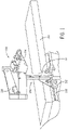
- FIG. 1 is a schematic diagram of an exemplary medical bed or table with a medical device mounted to the medical bed or table in accordance with an embodiment.
- a medical bed or table 100 includes a rail 102.
- a medical device 104 may be mounted to the table 100 using the rail 102.
- the medical device 104 includes an arm 106 that has a lower portion 108 and is used to support an instrument or system used in a medical procedure.
- the arm 106 may include an articulated upper portion 110.
- the arm 106 also includes a base 112 that is configured to mount and secure the medical device 104 to the rail 102.
- the instrument or system supported by the arm 106 may be, for example, a robotic catheter system, an IV pole, a monitor, a contrast solution injector, etc.
- an exemplary robotic catheter system 114 is shown attached to the arm 106.
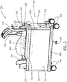
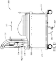
- FIG. 2 is a perspective view of a mobile support system in a first position in accordance with an embodiment
- FIG.3 is a perspective view of a mobile support system in a second position in accordance with an embodiment.
- a mobile support 200 e.g., a cart
- body 202 having a housing 204.
- the housing 204 includes a top surface 206, a bottom surface 208, a first side 210, a second side 212, a first end 214 and a second end 216. While a rectangular or cube shaped housing is shown, in other embodiments, the housing of the mobile support system 200 may have other shapes such as a cylinder and the housing may be a closed or open frame.
- a set of wheels 236 are attached to the bottom surface 208 of the housing 204.
- a floor brake 242 is also positioned on the bottom surface and is configured to be in a raised position when the mobile support 200 is used to transport and store the medical device and in a lowered position when the mobile support 200 is used to install the medical device on the rail of a bed or table and to remove the medical device from the rail of a bed or table as discussed further below.
- the first end 214 of the housing includes a handle 222, a foot pedal 224 and a button 228.
- a support arm 218 is positioned in a carriage 234 inside the housing 204. In FIG. 2 , the support arm 218 is located in a first position proximate the first end 214 of the housing 204. The first position shown in FIG. 2 may be used when the medical device is not in use and is being stored. In FIG. 3 , the support arm 218 is located at a second position proximate the second end 216 of the housing 204. The second position shown in FIG. 3 , may be used when the mobile support 200 is being used to install the medical device on or remove the medical device from the bed or table.
- a lower portion 236 of an arm of a medical device may be positioned in and adjacent to the support arm 218.
- the lower portion 236 of the arm is removably attached to the support arm 218 (and the mobile support 200).
- the support arm 218 may include a mounting block 241 (shown in FIG. 4 ) at a lower end of the support arm 218 proximate the top surface 206 of the housing and the carriage 234.
- the lower portion 236 of the arm of the medical device includes a base 240 that is configured to engage the mounting block 241 when the medical device is mounted on the cart. In embodiments described below, the base 240 and mounting block 241 interface vertically. The base 240 is also configured to engage the rail of a bed or table when the medical device is mounted to the bed or table.
- the lower portion 236 of the arm also includes a set of feet 238 that may be located on top of the bed or table and under, for example, a mattress when the medical device is mounted and secured to the bed or table. The feet 238 may be used to apply load directly onto the table surface in addition to a rail on the table.
- a side guide 220 is shown positioned along the top surface between the first end 214 and the second end 216 proximate to the first side 210 of the housing. In another embodiment, a side guide 220 may also be positioned along the top surface between the first end 214 and the second end 216 proximate to the second side 212.
- the side guide(s) 220 constrain and limit the range of motion of the support arm 218 and the arm 236 as they are moved from the first end 214 to the second end 216 of the housing 204 within the carriage 234. Limiting the range of motion of the support arm 218 and the arm 236 may result in increased stability of the mobile support system 200.
- a first rail detect guide 230 and a second rail detect guide 232 are located along the top surface proximate to the second end 216 of the housing.
- the first 230 and second 232 rail detect guide are configured to determine if the mobile support 200 and the arm 236 are in the correct position in relation to the rail of the bed or table for installation or removal of the medical device as described further below.
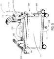
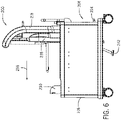
- FIG. 5 is a perspective view of a mobile support system in a first position in accordance with an embodiment.
- the mobile support 200 is wheeled up to the table so that the first rail detect guide 230 and the second rail detect guide 232 contact a rail 244 on the bed or table.
- the first rail detect guide 230 and the second rail detect guide 232 ensure that the table and rail 244 are in a correct height range.
- first 230 and second 232 rail detect guides each include a link or switch that when actuated by contact with the rail 244 activate the mechanisms (e.g., hydraulics) used to raise and lower the carriage 234 (and thereby the support arm 218 and lower portion 236 of the medical device arm) so that the medical device may be installed onto the rail 244.
- actuations of the links or switches in the first 230 and second 232 rail detect guides by contact with the rail 244 causes a bypass valve in a hydraulic circuit to close and switch the foot pedal 224 from a bypass mode to an actuation mode. In the bypass mode, the foot pedal 224 and mechanisms used to raise and lower the carriage 234 in the housing 204 of the mobile support 200 are inactive.
- the foot pedal 224 and the mechanisms used to raise and lower the carriage 234 are activated and a user may, for example, pump the foot pedal 224 to raise the carriage 234, support arm 218 and arm 236 upward in a vertical direction as indicated by arrow 253.
- a mechanism 246 may be used to raise the carriage 234 in response to the actuation of the foot pedal 224, for example, a scissor mechanism or lift as shown in FIG. 5 .
- the foot pedal 224 may be, for example, hydraulic or a mechanical linkage.
- actuation of the foot pedal 224 may cause the floor brake 242 to lower to contact the floor (as shown by arrow 251) and force or urge the mobile support 200 against the rail 244.
- FIG. 6 shows the carriage, support arm 218 and arm 236 in a raised position at the first position at the first end 214 of housing 204.
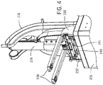
- FIG. 7 is a perspective view of a mobile support system in a second position in accordance with an embodiment.
- the support arm 218, arm 236 and carriage 234 have been moved in a horizontal direction (as shown by arrow 255) to the second position proximate the second end 216 of the housing 204.
- the horizontal movement may be provided using linear bearings (not shown).
- a bias spring (not shown) may be used to push or force the carriage 234 towards the second position and hold the carriage 234 in the second position.
- the bias spring may be implemented as an over center spring. In another embodiment, the bias spring may be implemented as a spring-loaded cam follower on a linear cam.
- the carriage 234, support arm 218 and arm 236 may then be lowered, for example, by actuating a button 228, towards the rail 244 (as shown by arrow 257) so that the arm 236 and base 240 are positioned on the rail 244.
- a mechanism such as a scissor mechanism may be used to lower the carriage 234.
- the carriage 234 continues to be lowered downwards to disengage from the base 240 of the arm 236.
- FIG. 8 shows the carriage and support arm 218 is a lowered position in second position at the second end 216 of the housing 204.
- the mobile support 200 may then be wheeled away from the bed or table.
- FIG. 9 is a perspective view looking upward towards a bottom portion of a base of an arm of a medical device in accordance with an embodiment
- FIG. 10 is a side view of a mounting block in a carriage of a mobile support system in accordance with an embodiment.
- base 240 includes a set of feet 238, a lip 252, a front side 245 and a bottom surface 250.
- a rail detect lever 254 is located on a bottom surface of lip 252. The rail detect lever 254 is used to make sure the arm base 240 is fully seated on the rail 244 (not shown) before the arm base 240 detaches from the mobile support 200.
- the rail detect lever 254 makes contact with the rail and either unlocks a first roller shaft 260 or a second roller shaft 262. In another embodiment, both the first roller shaft 260 and the second roller shaft 262 are locked and are unlocked when the rail detect lever 254 makes contact with the rail.
- first pin 268 and a second pin 270 are positioned in the first roller shaft 260 and the second roller shaft 262, respectively.
- First pin 268 and second pin 270 are shown in FIG. 10 having a cylindrical or round shape, however, other shapes may be used for the pins 268 and 270.
- the first 268 and second 370 pins of the mounting block 241 are shown in FIG. 10 .
- base 240 also includes a first roller 256 and a second roller 258 that are coupled to the first roller shaft 260 and the second roller shaft 262, respectively.
- first roller 256 and the second roller 258 are in a position (not shown in Fig. 9 ) so they lie substantially parallel to the first side 245 of the base 240 and do not protrude outward from and perpendicular to the first side 245 of the base 240.
- the mobile support 200 can continue to be lowered so as to disengage the first 268 and second 270 pin of the mounting block 241 from base 240.
- a follower pin 273 in first roller shaft 260 rotates the roller shaft 260 to move the first roller 256 to a position (shown in FIG.
- Base 240 also includes a friction brake 266 positioned on the first side 245 of the base 240 and a brake release 264 positioned in the bottom surface 250 of the base 240.
- a brake release pin 272 (shown in FIG. 10 ) on the mounting block 241 is positioned in the brake release 264.
- Brake release pin 272 is shown in FIG. 10 having a rectangular shape, however, other shapes may be used for the brake release pin 272.
- the brake 266 is applied and forced against the rail (e.g., a spring-loaded brake) to secure the base 240 to the rail as shown in FIG. 11.
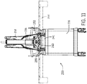
- FIG. 11 is a front view of a mobile support system in accordance with an embodiment.
- the support arm 218 and arm 236 are in the second position proximate to the second end 216 of the mobile support 200.
- the base 240 of the arm 236 is seated on the rail 244 and the brake 266 is against the rail 244.
- the floor brake 242 is released and raises up from the floor.
- the mobile support 200 may then be wheeled away from the bed or table.
- the medical device mounted to the table is shown in FIG. 1 .
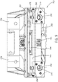
- FIG. 12 is a perspective view of a mobile support system with a lowered carriage in the second position
- FIG. 13 is a perspective view of a mobile support system with a raised carriage in the second position .
- the mobile support 200 is wheeled up to the table so that the first rail detect guide 230 and the second rail detect guide 232 contact the rail 244 on the bed or table. For clarity, only the rail 244 of the bed or table is shown. As discussed above with respect to FIG.
- the first 230 and second 232 rail detect guides each include a link or switch that when actuated by contact with the rail 244 unlock the mechanisms (e.g., hydraulics) used to raise and lower the carriage 234 (and thereby the support arm 218 and lower portion 236 of the medical device arm) so that the medical device may be removed from the rail 244.
- the mechanisms e.g., hydraulics
- a user may, for example, pump the foot pedal 224 to raise the carriage 234, support arm 218 and arm 236 upward in a vertical direction as indicated by arrow 263.
- actuation of the foot pedal 224 causes the floor brake to lower to contact the floor (as shown by arrow 261) and force or urge the mobile support 200 against the rail 244.
- the mounting block 241 on the mobile support 200 engages the base 240 of the arm 236.
- first pin 268 and a second pin 270 are positioned in the first roller shaft 260 and the second roller shaft 262, respectively.
- the follower pin 273 in first roller shaft 260 first unlocks the roller shaft 260 and then rotates the roller shaft 260 to move the first roller 256 to a position (not shown in Fig. 9 ) so it lies substantially parallel to the first side 245 of the base 240 and does not protrude outward from and perpendicular to the first side 245 of the base 240.
- the follower pin 275 in second roller shaft 262 first unlocks the roller shaft 262 and then rotates the roller shaft 262 to move the second roller 258 to a position (not shown in Fig. 9 ) so it lies substantially parallel to the first side 245 of the base 240 and does not protrude outward from and perpendicular to the first side 245 of the base 240.
- the brake release pin 272 shown in FIG. 10 on the mounting block 241 is positioned in the brake release 264.
- the brake release pin 272 As the brake release pin 272 is inserted in the brake release 264 as the mobile support 200 is raised, the brake 266 is released and no longer applies a force to the rail 244.
- the brake release pin 272 makes contact with a rocker in brake release 264 and the rocker may be attached to the brake with a tie rod.
- FIG. 14 is a perspective view of a mobile support system with a raised carriage at the first position in accordance with an embodiment.
- the support arm 218, arm 236 and carriage 234 have been moved in a horizontal direction (as shown by arrow 265) to the first position proximate the first end 214 of the housing 204.
- the horizontal movement may be provided using linear bearings (not shown).
- the carriage 234, support arm 218 and arm 236 may then be lowered (as shown by arrow 267), for example, by actuating a button 228, into the housing so that the arm 236 and base 240 are in a storage position as shown in Fig. 15 .
- a mechanism such as a scissor mechanism may be used to lower the carriage 234.
- the floor brake 242 releases and moves to a raised position (as shown by arrow 269).
- the mobile support 200 may then be wheeled away from the bed or table.
- This disclosure in particular, relates to aspects I - XXV of mobile support systems:
Landscapes
- Health & Medical Sciences (AREA)
- Engineering & Computer Science (AREA)
- Life Sciences & Earth Sciences (AREA)
- Public Health (AREA)
- Veterinary Medicine (AREA)
- Animal Behavior & Ethology (AREA)
- General Health & Medical Sciences (AREA)
- Biomedical Technology (AREA)
- Surgery (AREA)
- Transportation (AREA)
- Combustion & Propulsion (AREA)
- Chemical & Material Sciences (AREA)
- Mechanical Engineering (AREA)
- Nursing (AREA)
- Molecular Biology (AREA)
- Medical Informatics (AREA)
- Heart & Thoracic Surgery (AREA)
- Nuclear Medicine, Radiotherapy & Molecular Imaging (AREA)
- Pathology (AREA)
- Oral & Maxillofacial Surgery (AREA)
- Accommodation For Nursing Or Treatment Tables (AREA)
- Apparatus For Radiation Diagnosis (AREA)
Priority Applications (1)
| Application Number | Priority Date | Filing Date | Title |
|---|---|---|---|
| EP23217096.9A EP4335405A3 (de) | 2018-10-05 | 2019-10-03 | Mobiles stütz- und aufbewahrungssystem für eine medizinische vorrichtung |
Applications Claiming Priority (3)
| Application Number | Priority Date | Filing Date | Title |
|---|---|---|---|
| US16/152,811 US10611391B1 (en) | 2018-10-05 | 2018-10-05 | Mobile support and storage system for a medical device |
| PCT/US2019/054446 WO2020072747A1 (en) | 2018-10-05 | 2019-10-03 | Mobile support and storage system for a medical device |
| EP19868438.3A EP3843654B1 (de) | 2018-10-05 | 2019-10-03 | Mobiler träger für ein medizinprodukt |
Related Parent Applications (2)
| Application Number | Title | Priority Date | Filing Date |
|---|---|---|---|
| EP19868438.3A Division EP3843654B1 (de) | 2018-10-05 | 2019-10-03 | Mobiler träger für ein medizinprodukt |
| EP19868438.3A Division-Into EP3843654B1 (de) | 2018-10-05 | 2019-10-03 | Mobiler träger für ein medizinprodukt |
Related Child Applications (2)
| Application Number | Title | Priority Date | Filing Date |
|---|---|---|---|
| EP23217096.9A Division-Into EP4335405A3 (de) | 2018-10-05 | 2019-10-03 | Mobiles stütz- und aufbewahrungssystem für eine medizinische vorrichtung |
| EP23217096.9A Division EP4335405A3 (de) | 2018-10-05 | 2019-10-03 | Mobiles stütz- und aufbewahrungssystem für eine medizinische vorrichtung |
Publications (3)
| Publication Number | Publication Date |
|---|---|
| EP4119086A1 true EP4119086A1 (de) | 2023-01-18 |
| EP4119086B1 EP4119086B1 (de) | 2024-03-06 |
| EP4119086C0 EP4119086C0 (de) | 2024-03-06 |
Family
ID=70052913
Family Applications (3)
| Application Number | Title | Priority Date | Filing Date |
|---|---|---|---|
| EP19868438.3A Active EP3843654B1 (de) | 2018-10-05 | 2019-10-03 | Mobiler träger für ein medizinprodukt |
| EP23217096.9A Pending EP4335405A3 (de) | 2018-10-05 | 2019-10-03 | Mobiles stütz- und aufbewahrungssystem für eine medizinische vorrichtung |
| EP22194515.7A Active EP4119086B1 (de) | 2018-10-05 | 2019-10-03 | Mobiler träger und lagersystem für ein medizinprodukt |
Family Applications Before (2)
| Application Number | Title | Priority Date | Filing Date |
|---|---|---|---|
| EP19868438.3A Active EP3843654B1 (de) | 2018-10-05 | 2019-10-03 | Mobiler träger für ein medizinprodukt |
| EP23217096.9A Pending EP4335405A3 (de) | 2018-10-05 | 2019-10-03 | Mobiles stütz- und aufbewahrungssystem für eine medizinische vorrichtung |
Country Status (5)
| Country | Link |
|---|---|
| US (1) | US10611391B1 (de) |
| EP (3) | EP3843654B1 (de) |
| JP (3) | JP7082244B2 (de) |
| CN (3) | CN119112374A (de) |
| WO (1) | WO2020072747A1 (de) |
Families Citing this family (25)
| Publication number | Priority date | Publication date | Assignee | Title |
|---|---|---|---|---|
| US11052930B2 (en) * | 2017-06-16 | 2021-07-06 | Verb Surgical Inc. | Robotic arm cart having locking swivel joints and other position adjustment features and uses therefor |
| US10611391B1 (en) * | 2018-10-05 | 2020-04-07 | Corindus, Inc. | Mobile support and storage system for a medical device |
| IT201900001143A1 (it) * | 2019-01-25 | 2020-07-25 | Eurosets Srl | Attrezzatura per il trasporto di dispositivi biomedicali |
| US11246672B2 (en) | 2019-08-15 | 2022-02-15 | Auris Health, Inc. | Axial motion drive devices, systems, and methods for a robotic medical system |
| DE102020200831B4 (de) * | 2020-01-23 | 2023-11-30 | Dometic Sweden Ab | Getränkeservierwagen |
| CN111497922A (zh) * | 2020-05-26 | 2020-08-07 | 赵艳花 | 一种基于前后轮高度差实现下陡坡自动刹车的婴儿车 |
| CN111938959B (zh) * | 2020-08-03 | 2022-07-01 | 郑州大学第一附属医院 | 一种医疗护理用推车 |
| US12440289B2 (en) | 2022-08-01 | 2025-10-14 | Imperative Care, Inc. | Method of priming an interventional device assembly |
| US12564458B2 (en) | 2022-08-01 | 2026-03-03 | Imperative Care, Inc. | Method of robotically driving a multi catheter assembly above the aortic arch |
| US12564414B2 (en) | 2022-08-01 | 2026-03-03 | Imperative Care, Inc. | Method of supra-aortic access for a neurovascular procedure |
| US20230048388A1 (en) | 2021-08-12 | 2023-02-16 | Imperative Care, Inc. | Robotically driven interventional device |
| US12446979B2 (en) | 2022-08-01 | 2025-10-21 | Imperative Care, Inc. | Method of performing a multi catheter robotic neurovascular procedure |
| US12447317B2 (en) | 2022-08-01 | 2025-10-21 | Imperative Care, Inc. | Method of priming concentrically stacked interventional devices |
| US12419703B2 (en) | 2022-08-01 | 2025-09-23 | Imperative Care, Inc. | Robotic drive system for achieving supra-aortic access |
| CN113893040B (zh) * | 2021-09-23 | 2023-04-14 | 刘杰 | 一种妇产科临床器械的托架机构 |
| CN114261438A (zh) * | 2021-11-15 | 2022-04-01 | 深圳供电局有限公司 | 爬高工具及其使用方法 |
| CN114391971B (zh) * | 2021-12-24 | 2024-07-23 | 金华市子捷工具有限公司 | 一种可移动式医疗便携工具箱 |
| US20240041480A1 (en) | 2022-08-02 | 2024-02-08 | Imperative Care, Inc. | Multi catheter system with integrated fluidics management |
| US12433702B2 (en) | 2022-12-01 | 2025-10-07 | Imperative Care, Inc. | Telescoping drive table |
| JP2026500622A (ja) | 2022-12-01 | 2026-01-08 | インペラティブ ケア インコーポレイテッド | ロボットカテーテル駆動システムのためのコントローラ |
| CN121487771A (zh) | 2023-05-17 | 2026-02-06 | 因普瑞缇夫护理公司 | 用于多导管堆叠的流体控制系统 |
| WO2024249670A2 (en) | 2023-05-31 | 2024-12-05 | Imperative Care, Inc. | Magnetic coupling through a sterile field barrier |
| WO2025085588A1 (en) * | 2023-10-17 | 2025-04-24 | Care Surgical Limited | Surgical table extension for use with a surgical table |
| USD1119865S1 (en) | 2023-11-30 | 2026-03-24 | Imperative Care, Inc. | Controller |
| USD1102447S1 (en) | 2023-11-30 | 2025-11-18 | Imperative Care, Inc. | Display screen or portion thereof with graphical user interface |
Citations (4)
| Publication number | Priority date | Publication date | Assignee | Title |
|---|---|---|---|---|
| US20060163829A1 (en) * | 2005-01-10 | 2006-07-27 | Atlas Systems, Inc. | Modular patient support system |
| EP2145586A1 (de) * | 2008-07-16 | 2010-01-20 | BrainLAB AG | Adapter zur Fixierung eines Medizingerätes |
| US7845601B1 (en) * | 2006-11-09 | 2010-12-07 | Modular Services Company | Medical equipment transport system |
| US10034721B1 (en) * | 2017-09-27 | 2018-07-31 | Verb Surgical Inc. | Robotic arm cart having shock absorbing mechanisms and uses therefor |
Family Cites Families (39)
| Publication number | Priority date | Publication date | Assignee | Title |
|---|---|---|---|---|
| US3304609A (en) | 1966-02-16 | 1967-02-21 | Horowitz Norman | Dental equipment stand |
| US3922996A (en) | 1974-08-29 | 1975-12-02 | Brunswick Corp | Steering apparatus for outboard motors |
| DE2630857A1 (de) | 1976-07-09 | 1978-01-12 | Volkswagenwerk Ag | Handhabungsautomat |
| US4637494A (en) | 1983-11-15 | 1987-01-20 | Kabushiki Kaisha Toshiba | Apparatus for moving carriages along ladders |
| US4917619A (en) | 1987-12-26 | 1990-04-17 | Obara Corporation | Tool changer for welding robot |
| US5691898A (en) | 1995-09-27 | 1997-11-25 | Immersion Human Interface Corp. | Safe and low cost computer peripherals with force feedback for consumer applications |
| US5717480A (en) | 1995-10-27 | 1998-02-10 | Reliance Medical Products, Inc. | Ophthalmic instrument support and lighting system |
| WO2000009061A1 (en) * | 1998-08-14 | 2000-02-24 | The General Hospital Corporation Doing Business As Massachussets General Hospital | Transfer system for portable patient care apparatus |
| BR9916131A (pt) * | 1998-12-11 | 2001-11-06 | Hill Rom Co Inc | Montagens de cama, de apoio de paciente para uma cama articulada e de manìpulo de empurrar articulado para camas de hospital, e, cama de hospital |
| US6626445B2 (en) | 1999-12-02 | 2003-09-30 | Alcon Universal Ltd. | Cart for surgical console |
| US20010034721A1 (en) * | 2000-02-14 | 2001-10-25 | Jean-Pierre Boudreau | System and method for providing services to a remote user through a network |
| US20030032407A1 (en) | 2001-08-08 | 2003-02-13 | Ken Mages | System and method for preventing unauthorized use of a wireless or wired remote device |
| US6999849B2 (en) | 2002-01-24 | 2006-02-14 | John Clinton Bridges | Folding robotic system |
| CA2517889A1 (en) * | 2003-03-18 | 2004-09-30 | Hill-Rom Services, Inc. | Patient care equipment management system |
| EP1574197B1 (de) * | 2004-03-12 | 2007-05-30 | TRUMPF Kreuzer Medizin Systeme GmbH + Co. KG | System mit einem medizinischen Geräteträger, einem Gerätewagen, einer stationären Aufnahmeeinheit und einem Kopplungsmechanismus dafür |
| DE502004000710D1 (de) * | 2004-03-12 | 2006-07-20 | Trumpf Kreuzer Med Sys Gmbh | Medizinischer Gerätewagen mit einer Andockvorrichtung |
| US7003827B2 (en) * | 2004-06-21 | 2006-02-28 | Innovative Medical Products Inc. | Operating table support clamp |
| JP5097347B2 (ja) | 2005-12-26 | 2012-12-12 | オリンパスメディカルシステムズ株式会社 | 内視鏡および内視鏡システム |
| US20090248042A1 (en) | 2008-03-27 | 2009-10-01 | Kirschenman Mark B | Model catheter input device |
| US8390438B2 (en) | 2008-09-24 | 2013-03-05 | St. Jude Medical, Atrial Fibrillation Division, Inc. | Robotic catheter system including haptic feedback |
| US20110015484A1 (en) | 2009-07-16 | 2011-01-20 | Alvarez Jeffrey B | Endoscopic robotic catheter system |
| US8348287B1 (en) * | 2009-11-30 | 2013-01-08 | Smith Phillip J | Slab cart |
| ES2654585T3 (es) * | 2010-04-07 | 2018-02-14 | Alcon Research, Ltd. | Sistemas y procedimientos para frenado de consola |
| JP5514080B2 (ja) | 2010-11-11 | 2014-06-04 | 本田技研工業株式会社 | 工作機械用組立装置 |
| JP5651035B2 (ja) | 2011-02-09 | 2015-01-07 | 株式会社ソディック | 移動装置 |
| US8465203B2 (en) * | 2011-03-02 | 2013-06-18 | General Electric Company | Brake systems for C-arm positioning devices, apparatus containing the same and methods for using such systems |
| GB201115391D0 (en) * | 2011-09-06 | 2011-10-19 | Wootton Malcolm | Operating tables and accessories |
| CA2902067C (en) * | 2013-01-18 | 2017-12-05 | Alexander Bally | Modular rail adapter system |
| AU2015203964B2 (en) * | 2014-01-03 | 2019-03-21 | Innovative Orthopedic Technologies, Iot, Ag | Devices and methods for guiding and applying traction to a patient's leg during surgery |
| US20150223891A1 (en) * | 2014-02-07 | 2015-08-13 | Enovate Medical Llc | Medical cart access control |
| US20150223892A1 (en) | 2014-02-07 | 2015-08-13 | Enovate Medical, Llc | Work platform for a wheeled medical cart |
| US9463127B2 (en) * | 2014-12-05 | 2016-10-11 | Leon Hochman | Transporter table system |
| CN112545655B (zh) * | 2015-09-04 | 2024-09-20 | 马科外科公司 | 手术机器人系统、手术推车和推车的枢转托架 |
| EP3373839B1 (de) * | 2015-11-12 | 2024-09-04 | Covidien LP | Chirurgische robotersysteme zur überwachung angewandter kräfte |
| EP3448738A1 (de) * | 2016-04-29 | 2019-03-06 | Crown Equipment Corporation | Palettenhubwagentransportvorrichtung |
| WO2018061104A1 (ja) * | 2016-09-28 | 2018-04-05 | ミズホ株式会社 | 手術用頭部固定装置 |
| US10856948B2 (en) * | 2017-05-31 | 2020-12-08 | Verb Surgical Inc. | Cart for robotic arms and method and apparatus for registering cart to surgical table |
| US10333296B1 (en) * | 2018-04-20 | 2019-06-25 | Verb Surgical Inc. | Surgical robotic arm with wireless power supply interface |
| US10611391B1 (en) | 2018-10-05 | 2020-04-07 | Corindus, Inc. | Mobile support and storage system for a medical device |
-
2018
- 2018-10-05 US US16/152,811 patent/US10611391B1/en active Active
-
2019
- 2019-10-03 WO PCT/US2019/054446 patent/WO2020072747A1/en not_active Ceased
- 2019-10-03 EP EP19868438.3A patent/EP3843654B1/de active Active
- 2019-10-03 EP EP23217096.9A patent/EP4335405A3/de active Pending
- 2019-10-03 EP EP22194515.7A patent/EP4119086B1/de active Active
- 2019-10-03 JP JP2021518607A patent/JP7082244B2/ja active Active
- 2019-10-03 CN CN202411519207.XA patent/CN119112374A/zh active Pending
- 2019-10-03 CN CN202210872606.9A patent/CN115281844B/zh active Active
- 2019-10-03 CN CN201980080582.XA patent/CN113164218B/zh active Active
-
2022
- 2022-04-15 JP JP2022067477A patent/JP7350931B2/ja active Active
- 2022-04-15 JP JP2022067476A patent/JP7275349B2/ja active Active
Patent Citations (4)
| Publication number | Priority date | Publication date | Assignee | Title |
|---|---|---|---|---|
| US20060163829A1 (en) * | 2005-01-10 | 2006-07-27 | Atlas Systems, Inc. | Modular patient support system |
| US7845601B1 (en) * | 2006-11-09 | 2010-12-07 | Modular Services Company | Medical equipment transport system |
| EP2145586A1 (de) * | 2008-07-16 | 2010-01-20 | BrainLAB AG | Adapter zur Fixierung eines Medizingerätes |
| US10034721B1 (en) * | 2017-09-27 | 2018-07-31 | Verb Surgical Inc. | Robotic arm cart having shock absorbing mechanisms and uses therefor |
Also Published As
| Publication number | Publication date |
|---|---|
| EP4119086B1 (de) | 2024-03-06 |
| CN113164218A (zh) | 2021-07-23 |
| CN119112374A (zh) | 2024-12-13 |
| US10611391B1 (en) | 2020-04-07 |
| CN115281844A (zh) | 2022-11-04 |
| WO2020072747A1 (en) | 2020-04-09 |
| EP3843654A4 (de) | 2021-10-20 |
| CN113164218B (zh) | 2022-10-28 |
| EP4335405A3 (de) | 2024-06-05 |
| JP2022093407A (ja) | 2022-06-23 |
| JP2022093408A (ja) | 2022-06-23 |
| EP4119086C0 (de) | 2024-03-06 |
| JP7082244B2 (ja) | 2022-06-07 |
| JP2022504263A (ja) | 2022-01-13 |
| EP3843654A1 (de) | 2021-07-07 |
| EP4335405A2 (de) | 2024-03-13 |
| JP7275349B2 (ja) | 2023-05-17 |
| EP3843654B1 (de) | 2022-11-23 |
| CN115281844B (zh) | 2025-01-21 |
| JP7350931B2 (ja) | 2023-09-26 |
| US20200108850A1 (en) | 2020-04-09 |
Similar Documents
| Publication | Publication Date | Title |
|---|---|---|
| EP4119086A1 (de) | Mobiler träger und lagersystem für ein medizinprodukt | |
| US4691393A (en) | Angular tilt control mechanism for a wheeled stretcher | |
| CN1114745C (zh) | 滚轮组件提升机构 | |
| US8469651B2 (en) | Conveyance device using carriage | |
| US7100316B2 (en) | Collapsible ironing board | |
| KR20090049528A (ko) | 병원 반송용 스트레쳐 등의 철책 및 그 로크 기구 | |
| JP5001795B2 (ja) | 病院搬送用ストレッチャー等の柵及びそのロック機構 | |
| EP0911455B1 (de) | Möbelstück | |
| KR20190019650A (ko) | 높이 조절 책상 | |
| CN113454007B (zh) | 盖开闭装置 | |
| JP4001506B2 (ja) | ベッド用テーブル装置 | |
| JP3286284B2 (ja) | 脚台固定装置 | |
| US7207419B2 (en) | Safety lock system for a lift | |
| JP3456969B2 (ja) | 机の天板昇降装置 | |
| KR950008119Y1 (ko) | 승강기의 안전장치 | |
| CN221357153U (zh) | 医疗器械转运装置 | |
| JP2552705Y2 (ja) | ベッド | |
| US20250122056A1 (en) | Exhaust pipe lifting apparatuses and methods of use | |
| JPH04818Y2 (de) | ||
| US11039969B2 (en) | Overhead lift units, systems, and methods for mounting and transporting an overhead lift unit | |
| JP2006183708A (ja) | 免震装置 | |
| JPH0743167U (ja) | 台 車 | |
| JPH10184152A (ja) | 多段引出しキャビネットにおける施解錠装置 | |
| JPH06200576A (ja) | 床昇降装置 |
Legal Events
| Date | Code | Title | Description |
|---|---|---|---|
| PUAI | Public reference made under article 153(3) epc to a published international application that has entered the european phase |
Free format text: ORIGINAL CODE: 0009012 |
|
| STAA | Information on the status of an ep patent application or granted ep patent |
Free format text: STATUS: REQUEST FOR EXAMINATION WAS MADE |
|
| 17P | Request for examination filed |
Effective date: 20220908 |
|
| AC | Divisional application: reference to earlier application |
Ref document number: 3843654 Country of ref document: EP Kind code of ref document: P |
|
| AK | Designated contracting states |
Kind code of ref document: A1 Designated state(s): AL AT BE BG CH CY CZ DE DK EE ES FI FR GB GR HR HU IE IS IT LI LT LU LV MC MK MT NL NO PL PT RO RS SE SI SK SM TR |
|
| RBV | Designated contracting states (corrected) |
Designated state(s): AL AT BE BG CH CY CZ DE DK EE ES FI FR GB GR HR HU IE IS IT LI LT LU LV MC MK MT NL NO PL PT RO RS SE SI SK SM TR |
|
| RIC1 | Information provided on ipc code assigned before grant |
Ipc: B62B 7/04 20060101ALN20230829BHEP Ipc: B62B 3/04 20060101ALN20230829BHEP Ipc: A61G 13/10 20060101ALN20230829BHEP Ipc: A61B 90/57 20160101ALI20230829BHEP Ipc: A61G 12/00 20060101ALI20230829BHEP Ipc: A61B 50/13 20160101AFI20230829BHEP |
|
| GRAP | Despatch of communication of intention to grant a patent |
Free format text: ORIGINAL CODE: EPIDOSNIGR1 |
|
| STAA | Information on the status of an ep patent application or granted ep patent |
Free format text: STATUS: GRANT OF PATENT IS INTENDED |
|
| RIC1 | Information provided on ipc code assigned before grant |
Ipc: B62B 7/04 20060101ALN20230914BHEP Ipc: B62B 3/04 20060101ALN20230914BHEP Ipc: A61G 13/10 20060101ALN20230914BHEP Ipc: A61B 90/57 20160101ALI20230914BHEP Ipc: A61G 12/00 20060101ALI20230914BHEP Ipc: A61B 50/13 20160101AFI20230914BHEP |
|
| INTG | Intention to grant announced |
Effective date: 20231006 |
|
| GRAS | Grant fee paid |
Free format text: ORIGINAL CODE: EPIDOSNIGR3 |
|
| GRAA | (expected) grant |
Free format text: ORIGINAL CODE: 0009210 |
|
| STAA | Information on the status of an ep patent application or granted ep patent |
Free format text: STATUS: THE PATENT HAS BEEN GRANTED |
|
| AC | Divisional application: reference to earlier application |
Ref document number: 3843654 Country of ref document: EP Kind code of ref document: P |
|
| AK | Designated contracting states |
Kind code of ref document: B1 Designated state(s): AL AT BE BG CH CY CZ DE DK EE ES FI FR GB GR HR HU IE IS IT LI LT LU LV MC MK MT NL NO PL PT RO RS SE SI SK SM TR |
|
| REG | Reference to a national code |
Ref country code: CH Ref legal event code: EP |
|
| REG | Reference to a national code |
Ref country code: DE Ref legal event code: R096 Ref document number: 602019048076 Country of ref document: DE |
|
| REG | Reference to a national code |
Ref country code: IE Ref legal event code: FG4D |
|
| U01 | Request for unitary effect filed |
Effective date: 20240319 |
|
| RAP4 | Party data changed (patent owner data changed or rights of a patent transferred) |
Owner name: CORINDUS, INC. |
|
| U07 | Unitary effect registered |
Designated state(s): AT BE BG DE DK EE FI FR IT LT LU LV MT NL PT SE SI Effective date: 20240419 |
|
| PG25 | Lapsed in a contracting state [announced via postgrant information from national office to epo] |
Ref country code: GR Free format text: LAPSE BECAUSE OF FAILURE TO SUBMIT A TRANSLATION OF THE DESCRIPTION OR TO PAY THE FEE WITHIN THE PRESCRIBED TIME-LIMIT Effective date: 20240607 |
|
| PG25 | Lapsed in a contracting state [announced via postgrant information from national office to epo] |
Ref country code: HR Free format text: LAPSE BECAUSE OF FAILURE TO SUBMIT A TRANSLATION OF THE DESCRIPTION OR TO PAY THE FEE WITHIN THE PRESCRIBED TIME-LIMIT Effective date: 20240306 Ref country code: RS Free format text: LAPSE BECAUSE OF FAILURE TO SUBMIT A TRANSLATION OF THE DESCRIPTION OR TO PAY THE FEE WITHIN THE PRESCRIBED TIME-LIMIT Effective date: 20240606 |
|
| PG25 | Lapsed in a contracting state [announced via postgrant information from national office to epo] |
Ref country code: ES Free format text: LAPSE BECAUSE OF FAILURE TO SUBMIT A TRANSLATION OF THE DESCRIPTION OR TO PAY THE FEE WITHIN THE PRESCRIBED TIME-LIMIT Effective date: 20240306 |
|
| PG25 | Lapsed in a contracting state [announced via postgrant information from national office to epo] |
Ref country code: RS Free format text: LAPSE BECAUSE OF FAILURE TO SUBMIT A TRANSLATION OF THE DESCRIPTION OR TO PAY THE FEE WITHIN THE PRESCRIBED TIME-LIMIT Effective date: 20240606 Ref country code: NO Free format text: LAPSE BECAUSE OF FAILURE TO SUBMIT A TRANSLATION OF THE DESCRIPTION OR TO PAY THE FEE WITHIN THE PRESCRIBED TIME-LIMIT Effective date: 20240606 Ref country code: HR Free format text: LAPSE BECAUSE OF FAILURE TO SUBMIT A TRANSLATION OF THE DESCRIPTION OR TO PAY THE FEE WITHIN THE PRESCRIBED TIME-LIMIT Effective date: 20240306 Ref country code: GR Free format text: LAPSE BECAUSE OF FAILURE TO SUBMIT A TRANSLATION OF THE DESCRIPTION OR TO PAY THE FEE WITHIN THE PRESCRIBED TIME-LIMIT Effective date: 20240607 Ref country code: ES Free format text: LAPSE BECAUSE OF FAILURE TO SUBMIT A TRANSLATION OF THE DESCRIPTION OR TO PAY THE FEE WITHIN THE PRESCRIBED TIME-LIMIT Effective date: 20240306 |
|
| PG25 | Lapsed in a contracting state [announced via postgrant information from national office to epo] |
Ref country code: IS Free format text: LAPSE BECAUSE OF FAILURE TO SUBMIT A TRANSLATION OF THE DESCRIPTION OR TO PAY THE FEE WITHIN THE PRESCRIBED TIME-LIMIT Effective date: 20240706 |
|
| PG25 | Lapsed in a contracting state [announced via postgrant information from national office to epo] |
Ref country code: SM Free format text: LAPSE BECAUSE OF FAILURE TO SUBMIT A TRANSLATION OF THE DESCRIPTION OR TO PAY THE FEE WITHIN THE PRESCRIBED TIME-LIMIT Effective date: 20240306 |
|
| PG25 | Lapsed in a contracting state [announced via postgrant information from national office to epo] |
Ref country code: CZ Free format text: LAPSE BECAUSE OF FAILURE TO SUBMIT A TRANSLATION OF THE DESCRIPTION OR TO PAY THE FEE WITHIN THE PRESCRIBED TIME-LIMIT Effective date: 20240306 |
|
| PG25 | Lapsed in a contracting state [announced via postgrant information from national office to epo] |
Ref country code: PL Free format text: LAPSE BECAUSE OF FAILURE TO SUBMIT A TRANSLATION OF THE DESCRIPTION OR TO PAY THE FEE WITHIN THE PRESCRIBED TIME-LIMIT Effective date: 20240306 |
|
| PG25 | Lapsed in a contracting state [announced via postgrant information from national office to epo] |
Ref country code: SK Free format text: LAPSE BECAUSE OF FAILURE TO SUBMIT A TRANSLATION OF THE DESCRIPTION OR TO PAY THE FEE WITHIN THE PRESCRIBED TIME-LIMIT Effective date: 20240306 |
|
| PG25 | Lapsed in a contracting state [announced via postgrant information from national office to epo] |
Ref country code: SM Free format text: LAPSE BECAUSE OF FAILURE TO SUBMIT A TRANSLATION OF THE DESCRIPTION OR TO PAY THE FEE WITHIN THE PRESCRIBED TIME-LIMIT Effective date: 20240306 Ref country code: SK Free format text: LAPSE BECAUSE OF FAILURE TO SUBMIT A TRANSLATION OF THE DESCRIPTION OR TO PAY THE FEE WITHIN THE PRESCRIBED TIME-LIMIT Effective date: 20240306 Ref country code: RO Free format text: LAPSE BECAUSE OF FAILURE TO SUBMIT A TRANSLATION OF THE DESCRIPTION OR TO PAY THE FEE WITHIN THE PRESCRIBED TIME-LIMIT Effective date: 20240306 Ref country code: PL Free format text: LAPSE BECAUSE OF FAILURE TO SUBMIT A TRANSLATION OF THE DESCRIPTION OR TO PAY THE FEE WITHIN THE PRESCRIBED TIME-LIMIT Effective date: 20240306 Ref country code: IS Free format text: LAPSE BECAUSE OF FAILURE TO SUBMIT A TRANSLATION OF THE DESCRIPTION OR TO PAY THE FEE WITHIN THE PRESCRIBED TIME-LIMIT Effective date: 20240706 Ref country code: CZ Free format text: LAPSE BECAUSE OF FAILURE TO SUBMIT A TRANSLATION OF THE DESCRIPTION OR TO PAY THE FEE WITHIN THE PRESCRIBED TIME-LIMIT Effective date: 20240306 |
|
| U20 | Renewal fee for the european patent with unitary effect paid |
Year of fee payment: 6 Effective date: 20241018 |
|
| REG | Reference to a national code |
Ref country code: DE Ref legal event code: R097 Ref document number: 602019048076 Country of ref document: DE |
|
| RAP4 | Party data changed (patent owner data changed or rights of a patent transferred) |
Owner name: SIEMENS HEALTHINEERS ENDOVASCULAR ROBOTICS, INC. |
|
| U1H | Name or address of the proprietor changed after the registration of the unitary effect |
Owner name: SIEMENS HEALTHINEERS ENDOVASCULAR ROBOTICS, INC.; US |
|
| PLBE | No opposition filed within time limit |
Free format text: ORIGINAL CODE: 0009261 |
|
| STAA | Information on the status of an ep patent application or granted ep patent |
Free format text: STATUS: NO OPPOSITION FILED WITHIN TIME LIMIT |
|
| 26N | No opposition filed |
Effective date: 20241209 |
|
| REG | Reference to a national code |
Ref country code: CH Ref legal event code: PL |
|
| PG25 | Lapsed in a contracting state [announced via postgrant information from national office to epo] |
Ref country code: MC Free format text: LAPSE BECAUSE OF FAILURE TO SUBMIT A TRANSLATION OF THE DESCRIPTION OR TO PAY THE FEE WITHIN THE PRESCRIBED TIME-LIMIT Effective date: 20240306 |
|
| PG25 | Lapsed in a contracting state [announced via postgrant information from national office to epo] |
Ref country code: CH Free format text: LAPSE BECAUSE OF NON-PAYMENT OF DUE FEES Effective date: 20241031 |
|
| PG25 | Lapsed in a contracting state [announced via postgrant information from national office to epo] |
Ref country code: IE Free format text: LAPSE BECAUSE OF NON-PAYMENT OF DUE FEES Effective date: 20241003 |
|
| U20 | Renewal fee for the european patent with unitary effect paid |
Year of fee payment: 7 Effective date: 20251020 |
|
| PGFP | Annual fee paid to national office [announced via postgrant information from national office to epo] |
Ref country code: GB Payment date: 20251111 Year of fee payment: 7 |
|
| PG25 | Lapsed in a contracting state [announced via postgrant information from national office to epo] |
Ref country code: CY Free format text: LAPSE BECAUSE OF FAILURE TO SUBMIT A TRANSLATION OF THE DESCRIPTION OR TO PAY THE FEE WITHIN THE PRESCRIBED TIME-LIMIT; INVALID AB INITIO Effective date: 20191003 |
|
| PG25 | Lapsed in a contracting state [announced via postgrant information from national office to epo] |
Ref country code: HU Free format text: LAPSE BECAUSE OF FAILURE TO SUBMIT A TRANSLATION OF THE DESCRIPTION OR TO PAY THE FEE WITHIN THE PRESCRIBED TIME-LIMIT; INVALID AB INITIO Effective date: 20191003 |