EP4117153B1 - Schenkelpol-hybridanregungsmotor - Google Patents
Schenkelpol-hybridanregungsmotor Download PDFInfo
- Publication number
- EP4117153B1 EP4117153B1 EP22724395.3A EP22724395A EP4117153B1 EP 4117153 B1 EP4117153 B1 EP 4117153B1 EP 22724395 A EP22724395 A EP 22724395A EP 4117153 B1 EP4117153 B1 EP 4117153B1
- Authority
- EP
- European Patent Office
- Prior art keywords
- permanent magnet
- salient pole
- axial
- rotor
- assembly
- Prior art date
- Legal status (The legal status is an assumption and is not a legal conclusion. Google has not performed a legal analysis and makes no representation as to the accuracy of the status listed.)
- Active
Links
Images

Classifications
-
- H—ELECTRICITY
- H02—GENERATION; CONVERSION OR DISTRIBUTION OF ELECTRIC POWER
- H02K—DYNAMO-ELECTRIC MACHINES
- H02K16/00—Machines with more than one rotor or stator
- H02K16/02—Machines with one stator and two or more rotors
-
- H—ELECTRICITY
- H02—GENERATION; CONVERSION OR DISTRIBUTION OF ELECTRIC POWER
- H02K—DYNAMO-ELECTRIC MACHINES
- H02K1/00—Details of the magnetic circuit
- H02K1/06—Details of the magnetic circuit characterised by the shape, form or construction
- H02K1/12—Stationary parts of the magnetic circuit
- H02K1/14—Stator cores with salient poles
-
- H—ELECTRICITY
- H02—GENERATION; CONVERSION OR DISTRIBUTION OF ELECTRIC POWER
- H02K—DYNAMO-ELECTRIC MACHINES
- H02K21/00—Synchronous motors having permanent magnets; Synchronous generators having permanent magnets
- H02K21/02—Details
- H02K21/04—Windings on magnets for additional excitation ; Windings and magnets for additional excitation
- H02K21/046—Windings on magnets for additional excitation ; Windings and magnets for additional excitation with rotating permanent magnets and stationary field winding
-
- H—ELECTRICITY
- H02—GENERATION; CONVERSION OR DISTRIBUTION OF ELECTRIC POWER
- H02K—DYNAMO-ELECTRIC MACHINES
- H02K1/00—Details of the magnetic circuit
- H02K1/06—Details of the magnetic circuit characterised by the shape, form or construction
- H02K1/12—Stationary parts of the magnetic circuit
-
- H—ELECTRICITY
- H02—GENERATION; CONVERSION OR DISTRIBUTION OF ELECTRIC POWER
- H02K—DYNAMO-ELECTRIC MACHINES
- H02K1/00—Details of the magnetic circuit
- H02K1/06—Details of the magnetic circuit characterised by the shape, form or construction
- H02K1/22—Rotating parts of the magnetic circuit
- H02K1/24—Rotor cores with salient poles ; Variable reluctance rotors
-
- H—ELECTRICITY
- H02—GENERATION; CONVERSION OR DISTRIBUTION OF ELECTRIC POWER
- H02K—DYNAMO-ELECTRIC MACHINES
- H02K1/00—Details of the magnetic circuit
- H02K1/06—Details of the magnetic circuit characterised by the shape, form or construction
- H02K1/22—Rotating parts of the magnetic circuit
- H02K1/27—Rotor cores with permanent magnets
- H02K1/2706—Inner rotors
- H02K1/272—Inner rotors the magnetisation axis of the magnets being perpendicular to the rotor axis
- H02K1/2726—Inner rotors the magnetisation axis of the magnets being perpendicular to the rotor axis the rotor consisting of a single magnet or two or more axially juxtaposed single magnets
- H02K1/2733—Annular magnets
-
- H—ELECTRICITY
- H02—GENERATION; CONVERSION OR DISTRIBUTION OF ELECTRIC POWER
- H02K—DYNAMO-ELECTRIC MACHINES
- H02K1/00—Details of the magnetic circuit
- H02K1/06—Details of the magnetic circuit characterised by the shape, form or construction
- H02K1/22—Rotating parts of the magnetic circuit
- H02K1/27—Rotor cores with permanent magnets
- H02K1/2706—Inner rotors
- H02K1/272—Inner rotors the magnetisation axis of the magnets being perpendicular to the rotor axis
- H02K1/274—Inner rotors the magnetisation axis of the magnets being perpendicular to the rotor axis the rotor consisting of two or more circumferentially positioned magnets
- H02K1/2753—Inner rotors the magnetisation axis of the magnets being perpendicular to the rotor axis the rotor consisting of two or more circumferentially positioned magnets the rotor consisting of magnets or groups of magnets arranged with alternating polarity
- H02K1/276—Magnets embedded in the magnetic core, e.g. interior permanent magnets [IPM]
-
- H—ELECTRICITY
- H02—GENERATION; CONVERSION OR DISTRIBUTION OF ELECTRIC POWER
- H02K—DYNAMO-ELECTRIC MACHINES
- H02K11/00—Structural association of dynamo-electric machines with electric components or with devices for shielding, monitoring or protection
-
- H—ELECTRICITY
- H02—GENERATION; CONVERSION OR DISTRIBUTION OF ELECTRIC POWER
- H02K—DYNAMO-ELECTRIC MACHINES
- H02K16/00—Machines with more than one rotor or stator
- H02K16/04—Machines with one rotor and two stators
-
- H—ELECTRICITY
- H02—GENERATION; CONVERSION OR DISTRIBUTION OF ELECTRIC POWER
- H02K—DYNAMO-ELECTRIC MACHINES
- H02K3/00—Details of windings
- H02K3/46—Fastening of windings on the stator or rotor structure
-
- H—ELECTRICITY
- H02—GENERATION; CONVERSION OR DISTRIBUTION OF ELECTRIC POWER
- H02K—DYNAMO-ELECTRIC MACHINES
- H02K5/00—Casings; Enclosures; Supports
- H02K5/04—Casings or enclosures characterised by the shape, form or construction thereof
- H02K5/15—Mounting arrangements for bearing-shields or end plates
-
- H—ELECTRICITY
- H02—GENERATION; CONVERSION OR DISTRIBUTION OF ELECTRIC POWER
- H02K—DYNAMO-ELECTRIC MACHINES
- H02K1/00—Details of the magnetic circuit
- H02K1/06—Details of the magnetic circuit characterised by the shape, form or construction
- H02K1/22—Rotating parts of the magnetic circuit
- H02K1/24—Rotor cores with salient poles ; Variable reluctance rotors
- H02K1/246—Variable reluctance rotors
-
- H—ELECTRICITY
- H02—GENERATION; CONVERSION OR DISTRIBUTION OF ELECTRIC POWER
- H02K—DYNAMO-ELECTRIC MACHINES
- H02K1/00—Details of the magnetic circuit
- H02K1/06—Details of the magnetic circuit characterised by the shape, form or construction
- H02K1/22—Rotating parts of the magnetic circuit
- H02K1/27—Rotor cores with permanent magnets
- H02K1/2706—Inner rotors
- H02K1/272—Inner rotors the magnetisation axis of the magnets being perpendicular to the rotor axis
- H02K1/274—Inner rotors the magnetisation axis of the magnets being perpendicular to the rotor axis the rotor consisting of two or more circumferentially positioned magnets
- H02K1/2753—Inner rotors the magnetisation axis of the magnets being perpendicular to the rotor axis the rotor consisting of two or more circumferentially positioned magnets the rotor consisting of magnets or groups of magnets arranged with alternating polarity
- H02K1/276—Magnets embedded in the magnetic core, e.g. interior permanent magnets [IPM]
- H02K1/2766—Magnets embedded in the magnetic core, e.g. interior permanent magnets [IPM] having a flux concentration effect
-
- H—ELECTRICITY
- H02—GENERATION; CONVERSION OR DISTRIBUTION OF ELECTRIC POWER
- H02K—DYNAMO-ELECTRIC MACHINES
- H02K2201/00—Specific aspects not provided for in the other groups of this subclass relating to the magnetic circuits
- H02K2201/03—Machines characterised by aspects of the air-gap between rotor and stator
-
- Y—GENERAL TAGGING OF NEW TECHNOLOGICAL DEVELOPMENTS; GENERAL TAGGING OF CROSS-SECTIONAL TECHNOLOGIES SPANNING OVER SEVERAL SECTIONS OF THE IPC; TECHNICAL SUBJECTS COVERED BY FORMER USPC CROSS-REFERENCE ART COLLECTIONS [XRACs] AND DIGESTS
- Y02—TECHNOLOGIES OR APPLICATIONS FOR MITIGATION OR ADAPTATION AGAINST CLIMATE CHANGE
- Y02T—CLIMATE CHANGE MITIGATION TECHNOLOGIES RELATED TO TRANSPORTATION
- Y02T10/00—Road transport of goods or passengers
- Y02T10/60—Other road transportation technologies with climate change mitigation effect
- Y02T10/64—Electric machine technologies in electromobility
Definitions
- the present invention relates to the field of motors, and in particular to a salient pole type hybrid excitation motor.
- a permanent magnet motor attracts more and more attention due to the characteristics of high torque density, high efficiency, light weight and miniaturization, and has been widely used in various fields.
- the air gap magnetic field of the permanent magnet motor is determined by the magnetic conductance of a permanent magnet steel and a magnetic circuit, and is almost constant and difficult to adjust, which limits the further development and application of the permanent magnet motor.
- an electric excitation motor Compared with the permanent magnet motor, an electric excitation motor has the advantages of simple control, anti-vibration and easy assembly.
- the magnetic field intensity can be controlled by controlling an excitation current, so that a purpose of speed adjustment can be achieved, which is also a unique advantage of the (direct current) excitation motor.
- the excitation motor is controlled by high technology, high in reliability, and generally used in a high-power occasion.
- the excitation motor has a complex structure and a strict production process, cannot be small, energy-saving and easy to operate, and has disadvantages in energy-saving effect and production cost.
- EP 2 270 957A1 discloses a permanent magnet synchronization motor, in which A rotor (20) has a four-pole permanent magnet (31A) embedded in a rotor layered core. A gap (31G) is also arranged together with the permanent magnet between an inner circumferential layered core and an outer circumferential layered core. A permanent magnet of one pole is formed by two permanent magnets (31A and 31B) arranged so as to sandwich a gap (31G).
- Tm is the thickness of the permanent magnet in the inter-pole direction
- the air gap thickness in the d-axis direction is set to [1/2 ⁇ Tm] or below.
- a hybrid excitation motor not only has the high efficiency, high power density and many other characteristics of the permanent magnet motor, but also has the advantage of the electric excitation motor that the air gap magnetic field of the motor is smooth and adjustable.
- the hybrid excitation motor In an electric operation, the hybrid excitation motor has the advantages of large starting torque and wide speed adjustment range; and in a power generation operation, the hybrid excitation motor has a wide voltage regulation capability or a wide range variable-speed constant-voltage output capability. Due to the advantages of adjustable magnetic field, high torque density and high efficiency, the hybrid excitation motor is especially suitable for occasions such as constant power, wide speed regulation drive and constant voltage power generation, and has broad application prospects in fields such as aerospace, wind power generation, and electric vehicles.
- there are only a few types of hybrid excitation motors and an application range thereof is limited, and therefore, a hybrid excitation motor needs to be provided to expand the application range of the hybrid excitation motor.
- An object of the present invention is to provide a salient pole type hybrid excitation motor, so as to expand an application range of the hybrid excitation motor and to make an air gap magnetic field of the motor adjustable.
- the present invention provides a salient pole type hybrid excitation motor according to claim 1.
- the salient pole type hybrid excitation motor includes two sets of the permanent magnet rotors and two groups of the axial salient pole blocks, the two sets of the permanent magnet rotors sleeving the magnetic yoke and being arranged on two sides of the electromagnetic rotor respectively, and the two groups of the axial salient pole blocks being arranged on the other end portion of the two sets of the permanent magnet rotors respectively.
- one end of the permanent magnet rotor core close to the axial salient pole blocks is provided with a plurality of spaced positioning slots, the quantity of the axial salient pole blocks on a single side is the same as that of the positioning slots, the axial salient pole blocks are installed corresponding to the positioning slots, and at least part of each of the axial salient pole blocks is located in each of the positioning slots;
- the permanent magnet rotor core is provided with through holes used to install the permanent magnet steels, and the positioning slots are located between an peripheral surface of the permanent magnet rotor core and the through holes.
- the motor further includes end caps arranged at two ends of the rotor assembly, each of the end caps is provided with a magnetic conductive ring with a groove, and an excitation assembly is arranged in the groove.
- the excitation assembly includes an excitation coil and a coil bracket, the coil bracket being provided with a bracket slot for installing the excitation coil.
- a stator assembly includes a stator winding and a stator core, wherein a stator inner cavity includes a first inner cavity and a second inner cavity, the stator core surrounds and forms the first inner cavity, the stator winding surrounds and forms the second inner cavity, and the stator core provides support for the stator winding; in the axial direction of the stator assembly, the electromagnetic rotor and at least part of the permanent magnet rotors are located in the first inner cavity, and at least part of the excitation assemblies on at least a single side are located in the second inner cavity.
- each of the excitation assemblies does not exceed an axial outermost end of the stator winding, and an outermost end of the coil bracket does not exceed the axial outermost end of the stator winding.
- an axial end face of a radial outer portion of the magnetic conductive ring facing the rotor assembly is arranged opposite to an axial end face of the axial salient pole blocks, and a first axial auxiliary air gap exists therebetween.
- an axial end face of a radial inner portion of the magnetic conductive ring facing the rotor assembly is arranged opposite to an end face of the magnetic yoke, and a second axial auxiliary air gap exists therebetween.
- the radial salient poles of the electromagnetic rotor are N poles
- the axial salient pole blocks are S poles
- each of the axial salient pole blocks is arranged opposite to an S pole of one pole pair of the permanent magnet steels.
- the present invention changes the direction and magnitude of an electric excitation magnetic field in a case of power on by a combined action of electric excitation and permanent magnet excitation, so as to adjust an air gap magnetic field of a motor.
- double salient poles of a rotor assembly are formed by axial salient pole blocks and radial salient poles of an electromagnetic rotor, so that not only the permanent magnet excitation but also electromagnetic excitation of the motor can be achieved.
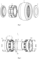
- 1- first excitation assembly 10- magnetic conductive ring, 11- excitation coil, 12- bracket slot, 13- bracket, 14- groove, 2- rotor assembly, 20- axial salient pole block, 21- permanent magnet rotor, 210- permanent magnet rotor core, 2101- positioning slot, 2102-through hole, 211- permanent magnet steel, 22- electromagnetic rotor, 220- radial salient pole, 23- magnetic yoke, 3- stator assembly, 30- stator winding, 31- stator core, 4- second excitation assembly, 5- first axial auxiliary air gap, 6- second axial auxiliary air gap, and 8- main air gap.
- Fig. 1 is a structural exploded diagram of a double salient pole type hybrid excitation motor according to an embodiment of the present invention.
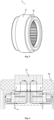
- Fig. 2 is a structural exploded diagram of a rotor assembly of a salient pole type hybrid excitation motor according to an embodiment of the present invention.
- the present invention provides a salient pole type hybrid excitation motor, mainly including a first excitation assembly 1, a rotor assembly 2, a stator assembly 3 and a second excitation assembly 4.
- the rotor assembly 2 is installed in the stator assembly 3, and the first excitation assembly 1 and the second excitation assembly 4 sleeve two ends of the stator assembly 3 to provide electric excitation for the rotor assembly 2.
- a motor air gap magnetic field of the hybrid excitation motor is smooth and adjustable.
- only one set of excitation assembly may be included, for example, only one of the first excitation assembly 1 and the second excitation assembly 4 is included, so that one of the first excitation assembly 1 and the second excitation assembly 4 is located at one of the two ends of the stator assembly 3, and the quantity of excitation assemblies corresponds to the quantity of permanent magnet rotors of the rotor assembly, for example, the quantity of excitation assemblies is the same as that of permanent magnet rotors of the rotor assembly.
- the rotor assembly 2 mainly includes axial salient pole blocks 20, an electromagnetic rotor 22, permanent magnet rotors 21 and a magnetic yoke 23, where the electromagnetic rotor 22 is constructed in an annular shape and sleeves the magnetic yoke 23, a plurality of radial salient poles 220 projecting outward are arranged at intervals on an annular peripheral surface of the electromagnetic rotor 22, and the radial salient poles 220 extend in the radial direction of the rotor assembly.
- the permanent magnet rotors 21 sleeve the magnetic yoke 23.
- the quantity of the permanent magnet rotors 21 is two, and the two permanent magnet rotors 21 are arranged on two sides of the electromagnetic rotor 22 respectively and attached to the electromagnetic rotor 22; each of the permanent magnet rotors 21 includes a permanent magnet rotor core 210 and permanent magnet steels 211, and the permanent magnet steels 211 are inserted into through holes 2102 in the permanent magnet rotor core 210 and form the permanent magnet rotor 21 together with the permanent magnet rotor core 210; in addition, the permanent magnet rotor core 210 is further provided with a plurality of spaced positioning slots 2101 for installing the axial salient pole blocks 20; the salient pole blocks 20 extend in the radial direction of the rotor assembly, and the axial salient pole blocks 20 cooperate with the radial salient poles 220 on the electromagnetic rotor 22 to jointly construct the electromagnetic pole of the electromagnetic rotor 22, and the axial salient pole blocks 20 are axially aligned with grooves formed between the radial salient
- double salient poles of the doubly rotor assembly 2 are formed by the axial salient pole blocks 20 and the radial salient poles 220 on the electromagnetic rotor 22, which realizes not only permanent magnet excitation but also electromagnetic excitation of the motor.
- the rotor assembly includes two permanent magnet rotors sharing one electromagnetic rotor 22, one end of the two permanent magnet rotors is in contact with the electromagnetic rotor, and the other end of the two permanent magnet rotors is provided with a group of axial salient pole blocks.
- the rotor assembly 2 has a triple salient pole structure, in which the radial salient poles 220 on the electromagnetic rotor 22 extend in the radial direction of the rotor assembly, and two groups of axial salient pole blocks extend in the axial direction of the rotor assembly.
- first excitation assembly 1 and the second excitation assembly 4 are arranged on end caps on two sides of the motor, without the need for a brush and a slip ring device, reliability and service life of the motor is further ensured.
- the permanent magnet rotor core 210 of the permanent magnet rotor 21 is provided with a plurality of positioning slots 2101, and the shape of the positioning slots 2101 corresponds to that of the axial salient pole blocks 20.
- an outer portion of the positioning slots 2101 is provided with through holes 2102, and through the through holes 2102, the permanent magnet steels 211 are installed on the permanent magnet rotor core 210.
- the axial salient pole blocks 20 are installed on one side of the permanent magnet rotor core 210 away from the electromagnetic rotor 22, that is, an outer side of the permanent magnet rotor core 210.
- the shape of the permanent magnet steels 211 is not specific, and can be selected according to an actual situation, including but not limited to various structures such as I-shaped, V-shaped, double V-shaped, and U-shaped. Furthermore, the shape of the through holes 2102 is not specified, and can be matched with the permanent magnet steels 211.
- the quantity of the radial salient poles 220 of the electromagnetic rotor 22 is associated with the pole pair quantity of the permanent magnet rotors 21, and the quantity of the radial salient poles 220 is less than or equal to the pole pair quantity of the permanent magnet rotors 21. Since the radial salient poles 220 and the axial salient pole blocks 20 are matched with each other, the quantity of the radial salient poles 220 and the quantity of the axial salient pole blocks 20 on a single side are the same.
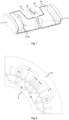
- the present embodiment takes the first excitation assembly 1 as an example, and the first excitation assembly 1 mainly includes a magnetic conductive ring 10, an excitation coil 11 and a bracket 13.
- the bracket 13 is provided with a bracket slot 12 for installing the excitation coil 11.
- the magnetic conductive ring 10 is provided with a groove 14, so that the magnetic conductive ring 10 is divided into a radial outer portion located at the outer side of the groove 14 and a radial inner portion located at the inner side of the groove 14 in the radial direction.
- the structure of the second excitation assembly 4 is the same as that of the first excitation assembly 1, so it is not described here.
- the second excitation assembly 4 and the first excitation assembly 1 are installed on two sides of the stator assembly 3, respectively, to provide electric excitation for the rotor assembly 2.
- the stator assembly 3 includes a stator core 31 and a stator winding 30.
- a stator inner cavity 32 is further formed in the stator assembly 3, and the stator inner cavity 32 includes a first inner cavity 321 and a second inner cavity 322, where the first inner cavity 321 is formed by being surrounded by the stator core 31, the second inner cavity 322 is formed by being surrounded by the stator winding 30, and the stator core 31 provides support for the stator winding 30.
- the electromagnetic rotor 22 and at least part of the permanent magnet rotors 21 are located in the first inner cavity 321, and at least a part of at least one excitation assembly of the first excitation assembly 1 and the second excitation assembly 4 is arranged inside the second inner cavity 322.
- the electromagnetic rotor 22 and the permanent magnet rotors 21 are located in the first inner cavity 321
- the axial salient pole blocks 20 are located in the second inner cavity 322
- the first excitation assembly 1 and the second excitation assembly 4 are at least partially located in the second inner cavity 322.
- the electromagnetic rotor 22 can be made by laminating silicon steel sheets or directly compression molding soft magnetic composite materials, with simple and convenient manufacturing and low cost; the magnetic yoke 23, the magnetic conductive ring 10 with the groove 14, and the axial salient pole blocks 20 are all made of the soft magnetic composite materials by directly compression molding, the manufacturing is also simple and convenient, and the cost is low. Moreover, the soft magnetic composite materials have low iron loss at a high frequency, which is conducive to improving the running efficiency at a high speed.
- the radial outer portion of the magnetic conductive ring 10 corresponds to the height of the axial salient pole blocks 20, an axial end face of the radial outer portion of the magnetic conductive ring 10 facing the rotor assembly 2 is opposite to an axial end face of the axial salient pole blocks 20, and a first axial auxiliary air gap 5 exists therebetween.
- an axial end face of the radial inner portion of the magnetic conductive ring 10 facing the rotor assembly 2 is arranged opposite to an end face of the magnetic yoke 23, and a second axial auxiliary air gap 6 exists therebetween.
- a complete magnetic path can be formed by the first axial auxiliary air gap 5 and the second axial auxiliary air gap 6.
- the radial salient poles 220 correspond to N poles and the axial salient pole blocks 20 correspond to S poles.
- a part of magnetic flux generated by a permanent magnet steel 211 starts from an N pole of the permanent magnet steel, passes through a main air gap 8, a stator teeth, a stator yoke, an adjacent stator teeth and the main air gap 8, reaches an adjacent S pole, and then passes through the rotor yoke to form a magnetic circuit closed loop;
- a part of the magnetic flux starts from the N pole of the permanent magnet steel 211, passes through the electromagnetic rotor 22, the magnetic yoke 23, the second axial auxiliary air gap, the inner side of the magnetic conductive ring 10 with the groove 14, the outer side of the magnetic conductive ring 10 with the groove 14, the first axial auxiliary air gap and the axial salient pole block 20, reaches the adjacent S pole, and then passes through the rotor yoke to form a magnetic circuit closed loop.
- a first part of the magnetic circuit passes through the main air gap, and generates output torque externally; a second part of the magnetic circuit is closed through the auxiliary air gaps, but not through the main air gap, so it belongs to a leakage flux part and does not work externally.
- the radial salient pole 220 of the electromagnetic rotor 22 is an N pole, that is, the magnetic flux generated by the electric excitation passes through the second axial auxiliary air gap, the magnetic yoke 23, the radial salient pole 220 of the electromagnetic rotor 22, the main air gap 8, the stator teeth, the stator yoke, the stator teeth, the main air gap 8, the adjacent S pole, the axial salient pole block 20, the first axial auxiliary air gap 5, the outer side of the magnetic conductive ring 10 with the groove 14, and the inner side of the magnetic conductive ring 10 with the groove 14, to form a closed loop.
- the radial salient pole 220 of the electromagnetic rotor 22 is also an N pole, and in parallel with the N pole of the permanent magnet steel to output energy to the main air gap together.
- the excitation winding coil 11 is powered by a reverse current and the radial salient pole 220 of the electromagnetic rotor 22 is an S pole, that is, the magnetic flux generated by the N pole of the permanent magnet steel 211 passes through the radial salient pole 220 of the electromagnetic rotor 22, the magnetic yoke 23, the second axial auxiliary air gap, the inner side of the magnetic conductive ring 10 with the groove 14, the outer side of the magnetic conductive ring 10 with the groove 14, the first axial auxiliary air gap, the axial salient pole block 20, and the S pole of the permanent magnet rotor to form a closed loop through the rotor yoke, so that most of the magnetic flux of the permanent magnet steel 211 does not pass through the main air gap.
- the adjustment of the main air gap magnetic field is achieved by powering on the excitation winding coil.
- two excitation sources namely permanent magnet steel excitation and exciting current excitation, are adopted, so that the adjustment and control of the air gap magnetic field are achieved.
- the exciting current provides magnetic assist, to improve the output torque at a low speed; and at a high speed, the exciting current provides weak magnetism, which is conducive to improving the running range of the motor, thereby achieving wide speed adjustment range.
Landscapes
- Engineering & Computer Science (AREA)
- Power Engineering (AREA)
- Permanent Field Magnets Of Synchronous Machinery (AREA)
- Permanent Magnet Type Synchronous Machine (AREA)
- Iron Core Of Rotating Electric Machines (AREA)
Claims (10)
- Hybrid-Erregungsmotor vom Schenkelpoltyp, umfassend eine Statoranordnung (3) und eine Rotoranordnung (2), wobei die Statoranordnung (3) einen inneren Statorhohlraum (32) aufweist und die Rotoranordnung (2) in dem inneren Statorhohlraum (32) angeordnet ist, wobei die Rotoranordnung (2) umfasst:ein magnetisches Joch (23);einen elektromagnetischen Rotor (22), der ringförmig ausgebildet ist und das magnetische Joch (23) ummantelt, wobei der elektromagnetische Rotor (22) in Abständen auf einer ringförmigen Umfangsfläche davon mit einer Vielzahl von radial vorstehenden Schenkelpolen (220) versehen ist;mindestens einen Satz von Permanentmagnetrotoren (21), die das magnetische Joch (23) ummanteln und auf einer Seite des elektromagnetischen Rotors (22) angeordnet sind, wobei jeder Satz von Permanentmagnetrotor (21) Folgendes umfasst:einen Permanentmagnet-Rotorkern (210), der ringförmig ausgebildet ist und das magnetische Joch (23) ummantelt, wobei eine Vielzahl von radial magnetisierten Permanentmagnetstählen (211) auf dem Permanentmagnet-Rotorkern (210) installiert und entlang der Umfangsrichtung des Permanentmagnet-Rotorkerns (210) verteilt ist und jeweils zwei benachbarte Permanentmagnetstähle (211) ein Polpaar bilden; undeine Vielzahl von axialen Schenkelpolblöcken (20), die der Vielzahl von radialen Schenkelpolen (220) des elektromagnetischen Rotors (22) entsprechen und an einer Außenseite des Permanentmagnet-Rotorkerns (210) installiert sind, wobei die axialen Schenkelpolblöcke (20) abwechselnd mit der Vielzahl von radialen Schenkelpolen (220) des elektromagnetischen Rotors (22) angeordnet sind, wobei die mehreren axialen Schenkelpolblöcke (20) und die mehreren radialen Schenkelpole (220) des elektromagnetischen Rotors (22) aneinander angepasst sind, wobei die Anzahl der radialen Schenkelpole (220) des elektromagnetischen Rotors (22) der Anzahl der Polpaare jedes Permanentmagnetrotors (21) zugeordnet und kleiner oder gleich ist, wobei die Anzahl der radialen Schenkelpole (220) und die Anzahl der axialen Schenkelpolblöcke (20) auf einer einzigen Seite gleich sind, wobei jeder radiale Schenkelpol (220) einem Permanentmagnetstahl (211) und jeder axiale Schenkelpolblock (20) einem anderen Permanentmagnetstähle (211) zugewandt ist, und wobei eine Polarität der Permanentmagnetstähle (211), die den axialen Schenkelpolblöcken (20) entsprechen, entgegengesetzt zu derjenigen der Permanentmagnetstähle (211) ist, die den radialen Schenkelpolen (220) des elektromagnetischen Rotors (22) entsprechen.
- Hybrid-Erregungsmotor vom Schenkelpoltyp nach Anspruch 1, wobei der Hybrid-Erregungsmotor vom Schenkelpoltyp zwei Sätze von Permanentmagnetrotoren (21) und zwei Gruppen von axialen Schenkelpolblöcken (20) umfasst, wobei die beiden Sätze von Permanentmagnetrotoren (21) das magnetische Joch (23) ummanteln und jeweils auf zwei Seiten des elektromagnetischen Rotors (22) angeordnet sind und die beiden Gruppen von axialen Schenkelpolblöcke (20) jeweils auf dem anderen Endabschnitt der beiden Sätze von Permanentmagnetrotoren (21) getrennt von dem elektromagnetischen Rotor (22) angeordnet sind.
- Hybrid-Erregungsmotor vom Schenkelpoltyp nach Anspruch 2, wobei ein Ende des Permanentmagnet-Rotorkerns (210) in der Nähe der axialen Schenkelpolblöcke (20) mit einer Vielzahl von beabstandeten Positionierungsschlitzen (2101) versehen ist, wobei die Anzahl der axialen Schenkelpolblöcke (20) auf einer einzigen Seite die gleiche wie die der Positionierungsschlitze (2101) ist, wobei die axialen Schenkelpolblöcke (20) entsprechend den Positionierungsschlitzen (2101) installiert sind und zumindest ein Teil jedes der axialen Schenkelpolblöcke (20) in jedem der Positionierungsschlitze (2101) angeordnet ist; wobei der Permanentmagnet-Rotorkern (210) mit Durchgangslöchern (2102) versehen ist, die zur Installation der Permanentmagnetstähle (211) verwendet werden, und wobei die Positionierungsschlitze (2101) zwischen einer Umfangsfläche des Permanentmagnet-Rotorkerns (210) und den Durchgangslöchern (2102) angeordnet sind.
- Hybrid-Erregungsmotor vom Schenkelpoltyp nach einem der Ansprüche 1 bis 3, wobei der Motor ferner Endkappen umfasst, die an zwei Enden der Rotoranordnung (2) angeordnet sind, wobei jede der Endkappen mit einem magnetisch leitenden Ring (10) mit einer Nut (14) versehen ist und eine Erregungsanordnung (1, 4) in der Nut (14) angeordnet ist.
- Hybrid-Erregungsmotor vom Schenkelpoltyp nach Anspruch 4, wobei die Erregungsanordnung (1, 4) eine Erregerspule (11) und eine Spulenhalterung (13) umfasst und die Spulenhalterung (13) mit einem Halterungsschlitz (12) zur Installation der Erregerspule (11) versehen ist.
- Hybrid-Erregungsmotor vom Schenkelpoltyp nach Anspruch 4, wobei die Statoranordnung (3) eine Statorwicklung (30) und einen Statorkern (31) umfasst, wobei der innere Statorhohlraum (32) einen ersten inneren Hohlraum (321) und einen zweiten inneren Hohlraum (322) umfasst, wobei der Statorkern (31) den ersten inneren Hohlraum (321) umgibt und bildet und die Statorwicklung (30) den zweiten inneren Hohlraum (322) umgibt und bildet, wobei der Statorkern (31) die Statorwicklung (30) abstützt; wobei in der axialen Richtung der Statoranordnung (3) der elektromagnetische Rotor (22) und mindestens ein Teil der Permanentmagnetrotoren (21) in dem ersten inneren Hohlraum (321) angeordnet sind und mindestens ein Teil der Erregeranordnungen (1, 4) auf mindestens einer Seite in dem zweiten inneren Hohlraum (322) angeordnet sind.
- Hybrid-Erregungsmotor vom Schenkelpoltyp nach Anspruch 5, wobei jede der Erregeranordnungen (1, 4) ein axial äußerstes Ende einer Statorwicklung (30) nicht überschreitet und ein äußerstes Ende der Spulenhalterung (13) das axial äußerste Ende der Statorwicklung (30) nicht überschreitet.
- Hybrid-Erregungsmotor vom Schenkelpoltyp nach Anspruch 5, wobei eine axiale Endfläche eines radialen äußeren Abschnitts des magnetisch leitenden Rings (10), der der Rotoranordnung (2) zugewandt ist, gegenüber einer axialen Endfläche der axialen Schenkelpolblöcke (20) angeordnet ist und ein erster axialer Hilfsluftspalt (5) dazwischen besteht.
- Hybrid-Erregungsmotor vom Schenkelpoltyp nach Anspruch 7, wobei eine axiale Endfläche eines radialen inneren Abschnitts des magnetisch leitenden Rings (10), der der Rotorbaugruppe (2) zugewandt ist, gegenüber einer Endfläche des magnetischen Jochs (23) angeordnet ist und ein zweiter axialer Hilfsluftspalt (6) dazwischen besteht.
- Hybrid-Erregungsmotor vom Schenkelpoltyp nach Anspruch 8 oder 9, wobei die radialen Schenkelpole (220) des elektromagnetischen Rotors (22) N-Pole sind, die axialen Schenkelpolblöcke (20) S-Pole sind und jeder der axialen Schenkelpolblöcke (20) gegenüber einem S-Pol eines Polpaares der Permanentmagnetstähle (211) angeordnet ist.
Applications Claiming Priority (2)
| Application Number | Priority Date | Filing Date | Title |
|---|---|---|---|
| CN202210042232.8A CN114389422B (zh) | 2022-01-14 | 2022-01-14 | 一种凸极式混合励磁电机 |
| PCT/CN2022/077377 WO2022105947A2 (zh) | 2022-01-14 | 2022-02-23 | 一种凸极式混合励磁电机 |
Publications (4)
| Publication Number | Publication Date |
|---|---|
| EP4117153A2 EP4117153A2 (de) | 2023-01-11 |
| EP4117153A4 EP4117153A4 (de) | 2023-08-23 |
| EP4117153B1 true EP4117153B1 (de) | 2024-09-11 |
| EP4117153C0 EP4117153C0 (de) | 2024-09-11 |
Family
ID=81202788
Family Applications (1)
| Application Number | Title | Priority Date | Filing Date |
|---|---|---|---|
| EP22724395.3A Active EP4117153B1 (de) | 2022-01-14 | 2022-02-23 | Schenkelpol-hybridanregungsmotor |
Country Status (6)
| Country | Link |
|---|---|
| US (1) | US12040667B2 (de) |
| EP (1) | EP4117153B1 (de) |
| JP (1) | JP7349036B2 (de) |
| KR (1) | KR102623591B1 (de) |
| CN (1) | CN114389422B (de) |
| WO (1) | WO2022105947A2 (de) |
Families Citing this family (9)
| Publication number | Priority date | Publication date | Assignee | Title |
|---|---|---|---|---|
| CN114844260B (zh) * | 2022-05-13 | 2025-09-23 | 无锡星驱动力科技有限公司 | 一种磁场可调电机和车辆 |
| CN115065211A (zh) * | 2022-06-29 | 2022-09-16 | 宁德时代电机科技有限公司 | 复合励磁的无弱磁永磁水冷驱动电机 |
| CN115276358B (zh) * | 2022-08-23 | 2025-05-09 | 江苏大学 | 一种多极少槽单元化永磁轮毂电机及协同控制系统和方法 |
| CN117040153B (zh) * | 2023-08-18 | 2026-03-03 | 深圳市科力尔运动控制技术有限公司 | 一种转子结构及步进电机 |
| CN117169718B (zh) * | 2023-09-21 | 2025-03-25 | 苏州新联电机有限公司 | 一种伺服电机耐久测试装置 |
| CN117220463B (zh) * | 2023-11-07 | 2024-03-01 | 天津九信科技有限公司 | 云台电机及增稳云台 |
| CN117471183B (zh) * | 2023-12-27 | 2024-03-12 | 苏州英磁新能源科技有限公司 | 一种定子铁损测量装置 |
| CN117674519B (zh) * | 2024-02-03 | 2024-06-14 | 泉州开普勒车用电机有限公司 | 一种复励式定子的生产方法 |
| CN118944361B (zh) * | 2024-07-10 | 2025-05-27 | 淄博华润燃气有限公司 | 燃气管道发电机 |
Family Cites Families (16)
| Publication number | Priority date | Publication date | Assignee | Title |
|---|---|---|---|---|
| EP1158652B1 (de) * | 2000-05-24 | 2007-09-26 | Matsushita Electric Industrial Co., Ltd. | Motor, elektrisches Fahrzeug und elektrisches Hybridfahrzeug |
| JP2002354729A (ja) | 2001-05-25 | 2002-12-06 | Hitachi Ltd | 永久磁石式回転電機およびそれを用いた空気調和機 |
| JP5141030B2 (ja) | 2006-02-14 | 2013-02-13 | 日産自動車株式会社 | 回転電機 |
| JP2009065803A (ja) * | 2007-09-07 | 2009-03-26 | Denso Corp | 磁石同期機 |
| KR100980565B1 (ko) * | 2007-10-18 | 2010-09-06 | 가부시키가이샤 이와키 | 자기부상모터 및 펌프 |
| CN101227130B (zh) * | 2007-11-19 | 2010-04-14 | 哈尔滨工业大学 | 转子磁场直接控制混合励磁同步电机 |
| CN101978576A (zh) * | 2008-03-19 | 2011-02-16 | 三洋电机株式会社 | 永久磁铁同步电动机 |
| CN102487234B (zh) * | 2010-12-03 | 2015-01-07 | 台达电子工业股份有限公司 | 旋转电机及其转子 |
| CN102315739B (zh) * | 2011-08-26 | 2013-02-06 | 北京航空航天大学 | 一种混合励磁发电机 |
| JP6019876B2 (ja) * | 2012-07-23 | 2016-11-02 | 株式会社ジェイテクト | 回転電機 |
| CN105680649B (zh) * | 2016-03-25 | 2018-08-28 | 南京工业大学 | 一种轴向径向磁通双凸极永磁电机 |
| CN205681195U (zh) * | 2016-04-20 | 2016-11-09 | 山东大学 | 一种双定子复合结构转子径轴向混合磁路永磁同步电机及电动汽车 |
| JP6193456B1 (ja) * | 2016-08-25 | 2017-09-06 | 株式会社ソシオリカ | 同期電動機 |
| JP2020096426A (ja) | 2018-12-11 | 2020-06-18 | 株式会社豊田中央研究所 | 回転電機 |
| CN110061603B (zh) * | 2019-01-25 | 2021-04-02 | 南京航空航天大学 | 一种转子磁路解耦型高速混合励磁同步电机 |
| JP7172979B2 (ja) * | 2019-12-25 | 2022-11-16 | トヨタ自動車株式会社 | 回転電機 |
-
2022
- 2022-01-14 CN CN202210042232.8A patent/CN114389422B/zh active Active
- 2022-02-23 EP EP22724395.3A patent/EP4117153B1/de active Active
- 2022-02-23 KR KR1020227014912A patent/KR102623591B1/ko active Active
- 2022-02-23 US US17/802,668 patent/US12040667B2/en active Active
- 2022-02-23 JP JP2022576575A patent/JP7349036B2/ja active Active
- 2022-02-23 WO PCT/CN2022/077377 patent/WO2022105947A2/zh not_active Ceased
Also Published As
| Publication number | Publication date |
|---|---|
| US12040667B2 (en) | 2024-07-16 |
| JP2023514757A (ja) | 2023-04-07 |
| US20230231453A1 (en) | 2023-07-20 |
| CN114389422B (zh) | 2023-12-22 |
| KR102623591B1 (ko) | 2024-01-11 |
| KR20230110439A (ko) | 2023-07-24 |
| EP4117153A4 (de) | 2023-08-23 |
| EP4117153A2 (de) | 2023-01-11 |
| CN114389422A (zh) | 2022-04-22 |
| WO2022105947A3 (zh) | 2022-09-15 |
| WO2022105947A2 (zh) | 2022-05-27 |
| JP7349036B2 (ja) | 2023-09-21 |
| EP4117153C0 (de) | 2024-09-11 |
Similar Documents
| Publication | Publication Date | Title |
|---|---|---|
| EP4117153B1 (de) | Schenkelpol-hybridanregungsmotor | |
| CN112564346B (zh) | 一种高转矩密度轴向磁场永磁电机转子结构及其电机 | |
| US20120212085A1 (en) | Axial-flux electric machine | |
| CN110460175B (zh) | 一种轴向磁通集中绕组型混合励磁电机 | |
| CN108418368B (zh) | 一种双转子混合励磁永磁同步电动机及其方法 | |
| US20170077771A1 (en) | Steel-magnet embedded mixed excitation motor | |
| CN104836398A (zh) | 转子聚磁式双定子横向磁场永磁同步电机 | |
| CN116722681A (zh) | 一种定子混合模块化永磁游标电机 | |
| CN117239969B (zh) | 一种外转子可变磁通交替极永磁同步电机 | |
| CN208174503U (zh) | 一种电动汽车用双转子混合励磁永磁同步电动机 | |
| CN108418375B (zh) | 一种电动汽车用多段轮辐交错转子永磁同步电机及其方法 | |
| DE60235685D1 (de) | Innen- und Aussenläufer elektrischer Motor mit Luftspaltringwicklung | |
| CN111245187B (zh) | 一种环形绕组双转子磁通反向电机 | |
| CN115987045B (zh) | 无刷反向爪极电磁与组合式非对称永磁混合励磁发电机 | |
| CN108599492B (zh) | 一种单元式轴向磁通开关磁阻电机 | |
| CN116247892B (zh) | 一种轴向环形永磁调磁永磁同步驱动电机及其方法 | |
| CN114844260B (zh) | 一种磁场可调电机和车辆 | |
| CN219554684U (zh) | 汽车用新型永磁发电机 | |
| EP4439927A1 (de) | Elektromotor, verdichter und kühlvorrichtung | |
| CN116231991B (zh) | 一种交流调磁型永磁同步电机及其方法 | |
| CN108462368B (zh) | 电动汽车用双定子集成式磁性行星齿轮复合电机 | |
| WO2021114452A1 (zh) | 一种永磁电机 | |
| CN223625650U (zh) | 一种用于电动飞机的轻量化永磁同步电机 | |
| CN116014942B (zh) | 一种轴向调磁永磁同步电机及其驱动方法 | |
| CN116247896B (zh) | 一种轴向双侧增磁永磁同步电机及其控制方法 |
Legal Events
| Date | Code | Title | Description |
|---|---|---|---|
| STAA | Information on the status of an ep patent application or granted ep patent |
Free format text: STATUS: THE INTERNATIONAL PUBLICATION HAS BEEN MADE |
|
| PUAI | Public reference made under article 153(3) epc to a published international application that has entered the european phase |
Free format text: ORIGINAL CODE: 0009012 |
|
| STAA | Information on the status of an ep patent application or granted ep patent |
Free format text: STATUS: REQUEST FOR EXAMINATION WAS MADE |
|
| 17P | Request for examination filed |
Effective date: 20221002 |
|
| AK | Designated contracting states |
Kind code of ref document: A2 Designated state(s): AL AT BE BG CH CY CZ DE DK EE ES FI FR GB GR HR HU IE IS IT LI LT LU LV MC MK MT NL NO PL PT RO RS SE SI SK SM TR |
|
| STAA | Information on the status of an ep patent application or granted ep patent |
Free format text: STATUS: EXAMINATION IS IN PROGRESS |
|
| A4 | Supplementary search report drawn up and despatched |
Effective date: 20230726 |
|
| RIC1 | Information provided on ipc code assigned before grant |
Ipc: H02K 21/04 20060101ALI20230720BHEP Ipc: H02K 11/00 20160101ALI20230720BHEP Ipc: H02K 3/46 20060101ALI20230720BHEP Ipc: H02K 1/12 20060101ALI20230720BHEP Ipc: H02K 1/276 20220101ALI20230720BHEP Ipc: H02K 1/24 20060101ALI20230720BHEP Ipc: H02K 16/02 20060101AFI20230720BHEP |
|
| 17Q | First examination report despatched |
Effective date: 20230821 |
|
| GRAP | Despatch of communication of intention to grant a patent |
Free format text: ORIGINAL CODE: EPIDOSNIGR1 |
|
| STAA | Information on the status of an ep patent application or granted ep patent |
Free format text: STATUS: GRANT OF PATENT IS INTENDED |
|
| RIC1 | Information provided on ipc code assigned before grant |
Ipc: H02K 21/04 20060101ALI20240403BHEP Ipc: H02K 11/00 20160101ALI20240403BHEP Ipc: H02K 3/46 20060101ALI20240403BHEP Ipc: H02K 1/12 20060101ALI20240403BHEP Ipc: H02K 1/276 20220101ALI20240403BHEP Ipc: H02K 1/24 20060101ALI20240403BHEP Ipc: H02K 16/02 20060101AFI20240403BHEP |
|
| GRAS | Grant fee paid |
Free format text: ORIGINAL CODE: EPIDOSNIGR3 |
|
| INTG | Intention to grant announced |
Effective date: 20240423 |
|
| GRAA | (expected) grant |
Free format text: ORIGINAL CODE: 0009210 |
|
| STAA | Information on the status of an ep patent application or granted ep patent |
Free format text: STATUS: THE PATENT HAS BEEN GRANTED |
|
| RAP1 | Party data changed (applicant data changed or rights of an application transferred) |
Owner name: WUXI INFIMOTION TECHNOLOGY CO., LTD. |
|
| AK | Designated contracting states |
Kind code of ref document: B1 Designated state(s): AL AT BE BG CH CY CZ DE DK EE ES FI FR GB GR HR HU IE IS IT LI LT LU LV MC MK MT NL NO PL PT RO RS SE SI SK SM TR |
|
| DAV | Request for validation of the european patent (deleted) | ||
| DAX | Request for extension of the european patent (deleted) | ||
| REG | Reference to a national code |
Ref country code: GB Ref legal event code: FG4D |
|
| REG | Reference to a national code |
Ref country code: CH Ref legal event code: EP |
|
| REG | Reference to a national code |
Ref country code: DE Ref legal event code: R096 Ref document number: 602022006072 Country of ref document: DE |
|
| REG | Reference to a national code |
Ref country code: IE Ref legal event code: FG4D |
|
| U01 | Request for unitary effect filed |
Effective date: 20240930 |
|
| U07 | Unitary effect registered |
Designated state(s): AT BE BG DE DK EE FI FR IT LT LU LV MT NL PT RO SE SI Effective date: 20241024 |
|
| PG25 | Lapsed in a contracting state [announced via postgrant information from national office to epo] |
Ref country code: NO Free format text: LAPSE BECAUSE OF FAILURE TO SUBMIT A TRANSLATION OF THE DESCRIPTION OR TO PAY THE FEE WITHIN THE PRESCRIBED TIME-LIMIT Effective date: 20241211 |
|
| PG25 | Lapsed in a contracting state [announced via postgrant information from national office to epo] |
Ref country code: GR Free format text: LAPSE BECAUSE OF FAILURE TO SUBMIT A TRANSLATION OF THE DESCRIPTION OR TO PAY THE FEE WITHIN THE PRESCRIBED TIME-LIMIT Effective date: 20241212 |
|
| PG25 | Lapsed in a contracting state [announced via postgrant information from national office to epo] |
Ref country code: HR Free format text: LAPSE BECAUSE OF FAILURE TO SUBMIT A TRANSLATION OF THE DESCRIPTION OR TO PAY THE FEE WITHIN THE PRESCRIBED TIME-LIMIT Effective date: 20240911 |
|
| PG25 | Lapsed in a contracting state [announced via postgrant information from national office to epo] |
Ref country code: RS Free format text: LAPSE BECAUSE OF FAILURE TO SUBMIT A TRANSLATION OF THE DESCRIPTION OR TO PAY THE FEE WITHIN THE PRESCRIBED TIME-LIMIT Effective date: 20241211 Ref country code: ES Free format text: LAPSE BECAUSE OF FAILURE TO SUBMIT A TRANSLATION OF THE DESCRIPTION OR TO PAY THE FEE WITHIN THE PRESCRIBED TIME-LIMIT Effective date: 20240911 |
|
| PG25 | Lapsed in a contracting state [announced via postgrant information from national office to epo] |
Ref country code: RS Free format text: LAPSE BECAUSE OF FAILURE TO SUBMIT A TRANSLATION OF THE DESCRIPTION OR TO PAY THE FEE WITHIN THE PRESCRIBED TIME-LIMIT Effective date: 20241211 Ref country code: NO Free format text: LAPSE BECAUSE OF FAILURE TO SUBMIT A TRANSLATION OF THE DESCRIPTION OR TO PAY THE FEE WITHIN THE PRESCRIBED TIME-LIMIT Effective date: 20241211 Ref country code: HR Free format text: LAPSE BECAUSE OF FAILURE TO SUBMIT A TRANSLATION OF THE DESCRIPTION OR TO PAY THE FEE WITHIN THE PRESCRIBED TIME-LIMIT Effective date: 20240911 Ref country code: GR Free format text: LAPSE BECAUSE OF FAILURE TO SUBMIT A TRANSLATION OF THE DESCRIPTION OR TO PAY THE FEE WITHIN THE PRESCRIBED TIME-LIMIT Effective date: 20241212 Ref country code: ES Free format text: LAPSE BECAUSE OF FAILURE TO SUBMIT A TRANSLATION OF THE DESCRIPTION OR TO PAY THE FEE WITHIN THE PRESCRIBED TIME-LIMIT Effective date: 20240911 |
|
| U20 | Renewal fee for the european patent with unitary effect paid |
Year of fee payment: 4 Effective date: 20250102 |
|
| PG25 | Lapsed in a contracting state [announced via postgrant information from national office to epo] |
Ref country code: IS Free format text: LAPSE BECAUSE OF FAILURE TO SUBMIT A TRANSLATION OF THE DESCRIPTION OR TO PAY THE FEE WITHIN THE PRESCRIBED TIME-LIMIT Effective date: 20250111 |
|
| PG25 | Lapsed in a contracting state [announced via postgrant information from national office to epo] |
Ref country code: SM Free format text: LAPSE BECAUSE OF FAILURE TO SUBMIT A TRANSLATION OF THE DESCRIPTION OR TO PAY THE FEE WITHIN THE PRESCRIBED TIME-LIMIT Effective date: 20240911 |
|
| PG25 | Lapsed in a contracting state [announced via postgrant information from national office to epo] |
Ref country code: CZ Free format text: LAPSE BECAUSE OF FAILURE TO SUBMIT A TRANSLATION OF THE DESCRIPTION OR TO PAY THE FEE WITHIN THE PRESCRIBED TIME-LIMIT Effective date: 20240911 Ref country code: PL Free format text: LAPSE BECAUSE OF FAILURE TO SUBMIT A TRANSLATION OF THE DESCRIPTION OR TO PAY THE FEE WITHIN THE PRESCRIBED TIME-LIMIT Effective date: 20240911 |
|
| PG25 | Lapsed in a contracting state [announced via postgrant information from national office to epo] |
Ref country code: SK Free format text: LAPSE BECAUSE OF FAILURE TO SUBMIT A TRANSLATION OF THE DESCRIPTION OR TO PAY THE FEE WITHIN THE PRESCRIBED TIME-LIMIT Effective date: 20240911 |
|
| PLBE | No opposition filed within time limit |
Free format text: ORIGINAL CODE: 0009261 |
|
| STAA | Information on the status of an ep patent application or granted ep patent |
Free format text: STATUS: NO OPPOSITION FILED WITHIN TIME LIMIT |
|
| 26N | No opposition filed |
Effective date: 20250612 |
|
| PG25 | Lapsed in a contracting state [announced via postgrant information from national office to epo] |
Ref country code: MC Free format text: LAPSE BECAUSE OF FAILURE TO SUBMIT A TRANSLATION OF THE DESCRIPTION OR TO PAY THE FEE WITHIN THE PRESCRIBED TIME-LIMIT Effective date: 20240911 |
|
| REG | Reference to a national code |
Ref country code: CH Ref legal event code: PL |
|
| PG25 | Lapsed in a contracting state [announced via postgrant information from national office to epo] |
Ref country code: CH Free format text: LAPSE BECAUSE OF NON-PAYMENT OF DUE FEES Effective date: 20250228 |
|
| PGFP | Annual fee paid to national office [announced via postgrant information from national office to epo] |
Ref country code: GB Payment date: 20251201 Year of fee payment: 5 |
|
| U20 | Renewal fee for the european patent with unitary effect paid |
Year of fee payment: 5 Effective date: 20251209 |
|
| PG25 | Lapsed in a contracting state [announced via postgrant information from national office to epo] |
Ref country code: IE Free format text: LAPSE BECAUSE OF NON-PAYMENT OF DUE FEES Effective date: 20250223 |