EP4102004B1 - Schutzvorrichtung für eine gebäudehülle - Google Patents
Schutzvorrichtung für eine gebäudehülle Download PDFInfo
- Publication number
- EP4102004B1 EP4102004B1 EP22176285.9A EP22176285A EP4102004B1 EP 4102004 B1 EP4102004 B1 EP 4102004B1 EP 22176285 A EP22176285 A EP 22176285A EP 4102004 B1 EP4102004 B1 EP 4102004B1
- Authority
- EP
- European Patent Office
- Prior art keywords
- protection device
- inner body
- cover
- profile
- outer body
- Prior art date
- Legal status (The legal status is an assumption and is not a legal conclusion. Google has not performed a legal analysis and makes no representation as to the accuracy of the status listed.)
- Active
Links
Images


Classifications
-
- A—HUMAN NECESSITIES
- A01—AGRICULTURE; FORESTRY; ANIMAL HUSBANDRY; HUNTING; TRAPPING; FISHING
- A01M—CATCHING, TRAPPING OR SCARING OF ANIMALS; APPARATUS FOR THE DESTRUCTION OF NOXIOUS ANIMALS OR NOXIOUS PLANTS
- A01M29/00—Scaring or repelling devices, e.g. bird-scaring apparatus
- A01M29/30—Scaring or repelling devices, e.g. bird-scaring apparatus preventing or obstructing access or passage, e.g. by means of barriers, spikes, cords, obstacles or sprinkled water
-
- E—FIXED CONSTRUCTIONS
- E04—BUILDING
- E04D—ROOF COVERINGS; SKY-LIGHTS; GUTTERS; ROOF-WORKING TOOLS
- E04D13/00—Special arrangements or devices in connection with roof coverings; Protection against birds; Roof drainage ; Sky-lights
- E04D13/004—Protection against birds, mice or the like
Definitions
- the present invention relates to a protective device for a building envelope according to patent claim 1 and the use of this protective device for a building envelope according to patent claim 11.
- Building envelopes such as roofs and facades ideally have a long lifespan and require little to no maintenance. Accordingly, they are not checked for years and damage that is invisible from the outside beneath the outermost layer of the building envelope can occur unnoticed and, after some time, lead to significant consequential damage.
- Animals such as martens and birds that penetrate through small openings of 3 cm or more in diameter at the edges and transitions of the building envelope can cause significant damage to the insulation layer underneath and even to the structure or construction of the building envelope.
- Noise from the movement of the animals or smells from decaying prey and faeces can represent further undesirable disturbances.
- a device which is attached to the edges of roofs in order to make openings impassable for animals.
- Angled prongs which are designed to be springy and elastic are attached to a strip-shaped support surface. The elasticity of the prongs allows them to be pressed down even in a small opening without lifting the roof, and on the other hand the animals that have already entered are not prevented from leaving the roof.
- a mesh wire is used to prevent birds and small animals from pecking, gnawing and biting at parts of the roof structure, thereby causing damage or gaining access to the interior of the roof.
- US2020103A , US2020103A and US2035862A disclose sealing strips for building envelopes comprising a shell, a malleable outer body and a stiffer inner body, the shell enclosing the outer body and the outer body surrounding the inner body.
- the US4081647A discloses a similar sealing strip for a microwave oven. It is from the US9867367B2 and from the US2019242181A1 It is known to use a filling of steel fibers or steel wool in sealing strips to keep out rodents.
- the present invention now has the object of providing a protective device for a building envelope which is easy and flexible to install, efficiently prevents animals from entering the interior of the building envelope and is durable over a long period of time.
- the protective device according to the invention for a building envelope comprises an easily deformable outer body 1 and a stiffer inner body 2 ( Figures 1a-d ).
- the outer body 1 is completely or partially covered by a cover 11 and the inner body 2 is completely or partially surrounded by the covered outer body 1.
- the outer body 1 comprises an easily deformable wool made of metal or plastic and forms a deformable cushion around the inner body 2.
- the cover 11 consists of a flexible grid, mesh or fabric made of metal. It is connected to the inner body 2 and serves to attach the outer body 1 around the inner body 2.
- the outer body 1 is arranged around the entire circumference of the inner body 2, and the whole is completely covered by the casing 11.
- the outer body 1 is arranged only on one side of the inner body 2, the cover 11 completely enveloping the exposed side of the outer body 1 and being connected to the inner body 2 in such a way that the outer body 1 is held thereon.
- the inner body 2 is preferably a strip of rigid but deformable material, preferably of metal such as lead ( Figure 1c ).
- the inner body 2 is a lead strip with a thickness of about 0.5 mm to 0.8 mm, a height h of 30 up to 100 mm and any length, which can be several meters and can be shortened to the required length by the user.
- the inner body 2 can also be completely or partially painted or coated. It is advantageous if the inner body 2 has a tab 21 at one or both of its ends, which are not surrounded by the outer body 1 ( Figure 1d ). If the protective device does not consist of a single part, but of several
- the tabs 21 are inserted between the outer body 1 and the inner body 2 of the next part of the protective device. This prevents gaps between two parts of the protective device placed next to each other, so that animals have no chance of slipping between them.
- the inner body 2 has cuts or it consists of several parts that are flexibly connected to each other. The inner body 2 is thus more flexible because it is easier to bend along the cuts or along two adjacent parts.
- Typical tiled roofs have small openings O through which animals such as martens or birds can slip. These openings are located between the tiles Z and the eaves at the bottom of the roof ( Figure 2a ) and between the tiles Z and valley flashings at the side edge of the roof ( Figure 2c ).
- the protective device D according to the invention can be inserted between the tiles Z and the underlying roof structure and serves to plug these openings O ( Figures 2b and 2d ).
- the inner body 2 is preferably in the form of a strip, the length of which is adapted to the corresponding edge of the roof.
- the height h of the inner body 2 is preferably at least a little larger than the diameter of the openings to be closed, so that the protective device can be easily bent, inserted and clamped.
- the inner body 2 is preferably a strip of uniform height h, which is bent more or less depending on the diameter of the openings ( Figure 3a-b ). Thanks to its deformability, the inner body 2 can be manually adapted to the shape of the roof edge, thus completely filling even openings of different sizes and extensions between the tiles Z and the underlying structure ( Figures 2b and 2d ). It is important for the inner body 2 that it can be manually deformed by a craftsman, either directly by hand or with a hand tool, but not by small animals such as martens or birds.
- the metal or plastic wool contained in the outer body 1 forms a cushion around the inner body 2, which adapts even better to the shape of the roof edge and ensures that the openings to be closed are completely plugged without having to deform the inner body 2 too precisely to the roof edge.
- the cover 11, consisting of a flexible grid, braid or fabric, also serves to protect the outer body 1 from pecking, gnawing and biting by the animals to be repelled. In particular, it prevents an opening from being created by pulling on the device, since either the grid deforms or the wool underneath is held back by the enveloping grid.
- a cover 11 made of Metal mesh or fabric is particularly advantageous because animals cannot gnaw on the metal threads, they are uncomfortable for the animals and can even easily injure them if they are pulled or gnawed too hard. Due to the great length of the threads used, they cannot be pulled out and pulling on a thread only makes the mesh tighter anyway.
- a circular knit fabric made of copper is used as the cover 11.
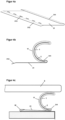
- the protective device is provided with a holder 3, which serves for easy positioning and mounting of the protective device on the edge of the roof ( Figure 4a ).
- the holder 3 comprises a first profile 31, which has a fold 311 on one edge.
- the first profile 31 is made of plastic or metal, in particular stainless steel, and preferably has the same length as the inner body 2 attached to it.
- an edge of the inner body 2 is inserted into the fold 311 and firmly clamped therein by pressing the fold 311 in ( Figure 4b ).
- the edge of the first profile 31 opposite the cover 311 is inserted into an existing water fold W attached to the roof ( Figure 4c ).
- the edge of the first profile 31 opposite the fold 311 has a bend 312.
- the first profile 31 can have openings 313 which serve to screw or nail the protective device.
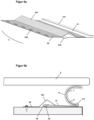
- the holder 3 also comprises a second profile 32, wherein the two profiles 31, 32 are connected to one another in parallel along their longitudinal direction ( Figure 5a ).
- the fold (311) is located on the edge of the first profile (31) opposite the second profile (32).
- the profiles 31, 32 are firmly connected to one another, preferably welded or riveted together, in particular they can be connected to one another by spot welding the second profile 32 onto the first profile 31.
- the second profile 32 is also made of plastic or metal, in particular stainless steel, and preferably has the same length as the inner body 2.
- the second profile 32 forms a raised web 321, which serves to bridge a water fold W on the edge of the roof and is obtained by bending or repeatedly folding the second profile 32 ( Figure 5b ).
- the end of the first profile 31 opposite the fold 311 to below the raised web 321 of the second profile 32 and into the water fold W.
- the second profile 32 may also have openings 322 for screwing or nailing the protection device to the roof structure.
- the protection device is dimensioned so that the inner and outer bodies 1, 2 are bent and clamped between the support 3 and the tiles Z in order to completely plug any passage between the tiles and the structure located underneath.
- An alternative fastening method is to attach an adhesive device, for example an adhesive tape or several adhesive dots, to the bracket 3.
- This fastening method is also possible for the protective device without a bracket, in which case the adhesive device is attached directly to the cover 11.
- the protective device can be easily attached anywhere, in particular around a roof window, or in other places where fastening with screws or nails is not possible or desired.
Landscapes
- Life Sciences & Earth Sciences (AREA)
- Engineering & Computer Science (AREA)
- Zoology (AREA)
- Insects & Arthropods (AREA)
- Pest Control & Pesticides (AREA)
- Wood Science & Technology (AREA)
- Birds (AREA)
- Environmental Sciences (AREA)
- Architecture (AREA)
- Civil Engineering (AREA)
- Structural Engineering (AREA)
- Catching Or Destruction (AREA)
- Building Environments (AREA)
Description
- Die vorliegende Erfindung betrifft eine Schutzvorrichtung für eine Gebäudehülle gemäss Patentanspruch 1 und die Verwendung dieser Schutzvorrichtung für eine Gebäudehülle gemäss Patentanspruch 11.
- Gebäudehüllen wie Dächer und Fassaden haben idealerweise eine lange Lebensdauer und benötigen wenig bis gar keinen Unterhalt. Entsprechend werden diese über Jahre hinweg nicht überprüft und von aussen unsichtbare Schäden unterhalb der äussersten Schicht der Gebäudehülle können unbemerkt entstehen und nach einiger Zeit zu erheblichen Folgeschäden führen.
- Tiere wie zum Beispiel Marder und Vögel, die durch kleine Öffnungen ab 3 cm Durchmesser an den Rändern und Übergängen der Gebäudehülle eindringen, können erhebliche Schäden an der darunter angeordneten Isolationsschicht und sogar an der Struktur oder Konstruktion der Gebäudehülle verursachen. Geräusche aufgrund der Bewegung der Tiere oder Gerüche verwesender Beutetiere und Fäkalien können noch weitere unerwünschte Störungen darstellen.
- In der
DE 10 2008 059 134 A1 wird eine Vorrichtung vorgestellt, welche an den Rändern von Dächern angebracht wird, um Öffnungen für Tiere unpassierbar zu machen. An einer leistenförmigen Auflagefläche werden winklig abstehende Zinken angebracht, die federnd elastisch ausgebildet sind. Die Elastizität der Zinken lässt zu, dass diese einerseits auch bei einer kleinen Öffnung heruntergedrückt werden können, ohne das Dach anzuheben, und andererseits werden die bereits eingedrungenen Tiere nicht daran gehindert, das Dach zu verlassen. - In der
DE 20 2012 005 768 U1 wird ein Gitterdraht dazu benutzt, Vögel und Kleintiere davon abzuhalten, an Teilen der Dachkonstruktion zu Hacken, Nagen und Beissen, und damit Schäden anzurichten oder einen Zugang ins Innere des Dachs freizulegen. - Den bekannten Vorrichtungen gemeinsam ist die eher aufwändige Montage sowie die Möglichkeit, dass durch Herunterdrücken der Zinken bzw. Verbiegen des Gitterdrahts Tiere sich trotzdem einen Zugang zum Innern des Dachs verschaffen können.
- Die Patentschriften
US2020103A ,US2020103A undUS2035862A offenbaren Dichtungsstreifen für Gebäudehüllen mit einer Hülle, einem formbaren Aussenkörper und einem steiferen Innenkörper, wobei die Hülle den Aussenkörper umfüllt und der Aussenkörper den Innenkörper umgibt. DieUS4081647A offenbart einen ähnlichen Dichtungsstreifen für ein Mikrowellengerät. Es ist aus derUS9867367B2 US2019242181A1 bekannt, eine Füllung aus Stahlfasern oder Stahlwolle in Dichtungsstreifen zu verwenden, um Nagetiere abzusperren. - Die vorliegende Erfindung stellt sich nunmehr die Aufgabe, eine Schutzvorrichtung für eine Gebäudehülle bereitzustellen, welche einfach und flexibel zu montieren ist, sowie das Eindringen von Tieren in das Innere der Gebäudehülle effizient verhindert und über lange Zeit beständig ist.
- Diese Aufgabe löst eine Schutzvorrichtung für eine Gebäudehülle mit den Merkmalen des Patentanspruches 1 und die Verwendung dieser Schutzvorrichtung für eine Gebäudehülle gemäss Patentanspruch 11. Weitere Merkmale und Ausführungsbeispiele gehen aus den abhängigen Ansprüchen hervor und deren Vorteile sind in der nachfolgenden Beschreibung erläutert.
- Die Zeichnungen zeigen:
- Figur 1a-b
- Ausführungsvarianten der Schutzvorrichtung, im Schnitt
- Figur 1c
- Perspektivansicht der Schutzvorrichtung
- Figur 1d
- Perspektivansicht einer gebogenen Schutzvorrichtung mit Lappen
- Figur 2a
- Unterer Rand eines Daches, ohne Schutzvorrichtung
- Figur 2b
- Unterer Rand eines Daches, mit Schutzvorrichtung
- Figur 2c
- Seitenrand eines Daches, ohne Schutzvorrichtung
- Figur 2d
- Seitenrand eines Daches, mit Schutzvorrichtung
- Figur 3a-b
- Schutzvorrichtung in Öffnungen unterschiedlicher Dimensionen zwischen zwei Teilen einer Gebäudehülle
- Figur 4a
- Perspektivansicht der Halterung
- Figur 4b
- Schutzvorrichtung mit Halterung
- Figur 4c
- Einsatz der Schutzvorrichtung mit Halterung zwischen zwei Teilen einer Gebäudehülle, im Schnitt
- Figur 5a
- Perspektivansicht einer Ausführungsvariante der Halterung
- Figur 5b
- Einsatz einer Ausführungsvariante der Schutzvorrichtung zwischen zwei Teilen einer Gebäudehülle, im Schnitt
- Die Figuren stellen mögliche Ausführungsbeispiele dar, welche in der nachfolgenden Beschreibung erläutert werden.
- Die erfindungsgemässe Schutzvorrichtung für eine Gebäudehülle umfasst einen leicht verformbaren Aussenkörper 1 und einen steiferen Innenkörper 2 (
Figuren 1a-d ). Der Aussenkörper 1 ist durch eine Hülle 11 vollständig oder teilweise umhüllt und der Innenkörper 2 ist mit dem umhüllten Aussenkörper 1 vollständig oder teilweise umgeben. Der Aussenkörper 1 umfasst eine leicht verformbare Wolle aus Metall oder Kunststoff und bildet um den Innenkörper 2 herum ein verformbares Kissen. Die Hülle 11 besteht aus einem flexiblen Gitter, Geflecht oder Gewebe aus Metall. Sie ist mit dem Innenkörper 2 verbunden und dient der Befestigung des Aussenkörpers 1 um den Innenkörper 2. In der Ausführungsvariante gemässFigur 1a ist der Aussenkörper 1 um den gesamten Umfang des Innenkörpers 2 angeordnet, und das Ganze wird durch die Hülle 11 vollständig umhüllt. In der Ausführungsvariante gemässFigur 1b ist der Aussenkörper 1 nur auf einer Seite des Innenkörpers 2 angeordnet, wobei die Hülle 11 die freiliegende Seite des Aussenkörpers 1 vollständig umhüllt und mit dem Innenkörper 2 derart verbunden ist, dass der Aussenkörper 1 daran festgehalten wird. Der Innenkörper 2 ist vorzugsweise ein Streifen aus steifem aber verformbarem Material, bevorzugt aus Metall wie zum Beispiel Blei (Figur 1c ). In der bevorzugten Ausführungsvariante ist der Innenkörper 2 ein Bleistreifen mit einer Dicke von etwa 0.5 mm bis 0.8 mm, einer Höhe h von 30 bis 100 mm und einer beliebigen Länge, die mehrere Meter betragen kann und durch den Benutzer auf die benötigte Länge gekürzt werden kann. Der Innenkörper 2 kann auch vollständig oder teilweise lackiert oder beschichtet sein. Von Vorteil ist es, wenn der Innenkörper 2 an einem oder beiden seiner Enden einen Lappen 21 aufweist, welche mit dem Aussenkörper 1 nicht umgeben sind (Figur 1d ). Wenn die Schutzvorrichtung nicht aus einem einzigen Teil besteht, sondern aus mehreren - Teilen, die nebeneinander angeordnet werden, werden die Lappen 21 zwischen dem Aussenkörper 1 und dem Innenkörper 2 des nächsten Teils der Schutzvorrichtung eingeführt. Dadurch werden Spalten zwischen zwei nebeneinander angeordneten Teilen der Schutzvorrichtung vermieden, so dass es für Tiere keine Möglichkeit gibt, dazwischen zu schlüpfen. In einer Ausführungsvariante der Schutzvorrichtung weist der Innenkörper 2 Schnitte auf oder er besteht aus mehreren Teilen, die flexibel miteinander verbunden sind. Der Innenkörper 2 wird dadurch flexibler, weil er entlang der Schnitte bzw. entlang zwei benachbarten Teile einfacher zu biegen ist.
- Typische Ziegeldächer weisen kleine Öffnungen O auf, durch welche Tiere wie Marder oder Vögel schlüpfen können. Diese Öffnungen befinden sich zwischen den Ziegeln Z und der Traufe am unteren Rand des Daches (
Figur 2a ) und zwischen den Ziegeln Z und Kehlblechen am Seitenrand des Daches (Figur 2c ). Die erfindungsgemässe Schutzvorrichtung D kann zwischen den Ziegeln Z und der darunterliegenden Dachstruktur eingesetzt werden und dient dem Stopfen dieser Öffnungen O (Figuren 2b und 2d ). Der Innenkörper 2 liegt vorzugsweise in Form eines Streifens vor, dessen Länge an den entsprechenden Rand des Dachs angepasst wird. Die Höhe h des Innenkörpers 2 ist vorzugsweise mindestens ein wenig grösser als der Durchmesser der zu schliessenden Öffnungen, so dass die Schutzvorrichtung leicht gebogen, darin eingeführt und geklemmt werden kann. Der Innenkörper 2 ist vorzugsweise ein Streifen mit gleichmässiger Höhe h, der je nach Durchmesser der Öffnungen mehr oder weniger stark gebogen wird (Figur 3a-b ). Dank seiner Verformbarkeit kann der Innenkörper 2 an die Form des Dachrandes manuell angepasst werden, wodurch auch Öffnungen unterschiedlicher Grösse und Ausdehnung zwischen den Ziegeln Z und der darunterliegenden Struktur vollständig gestopft werden (Figur 2b und 2d ). Wichtig ist beim Innenkörper 2, dass dieser durch einen Handwerker manuell verformbar ist, sei es direkt mit der Hand oder mit einem Handwerkzeug, jedoch nicht durch kleine Tiere wie Marder oder Vögel. Die im Aussenkörper 1 enthaltene Metall- oder Kunststoffwolle bildet ein Kissen um den Innenkörper 2, welches sich der Form des Dachrandes noch besser anpasst und das vollständige Stopfen der zu schliessenden Öffnungen gewährleistet, ohne den Innenkörper 2 allzu präzise an den Dachrand verformen zu müssen. Die Hülle 11, bestehend aus einem flexiblen Gitter, Geflecht oder Gewebe, dient ausserdem dem Schutz des Aussenkörpers 1 vor Hacken, Nagen und Beissen durch die abzuweisenden Tiere. Sie vermeidet insbesondere, dass durch Ziehen an der Vorrichtung eine Öffnung entstehen kann, da entweder das Gitter sich verformt oder die darunterliegende Wolle durch das umhüllende Gitter zurückgehalten wird. Eine Hülle 11 aus Metallgeflecht oder -gewebe ist besonders vorteilhaft, weil Tiere die Metallfäden nicht nagen können, diese für die Tiere unangenehm sind und diese sogar leicht verletzen können, wenn zu stark daran gezogen oder genagt wird. Aufgrund der grossen Länge der verwendeten Fäden können diese auch nicht herausgezogen werden, und durch Ziehen an einem Faden wird die Masche sowieso nur fester. In einer bevorzugten Ausführungsvariante der Schutzvorrichtung wird als Hülle 11 ein Rundstrickgewebe aus Kupfer verwendet. - In einer vorteilhaften Ausführungsvariante der Erfindung ist die Schutzvorrichtung mit einer Halterung 3 versehen, die der einfachen Positionierung und Montage der Schutzvorrichtung am Dachrand dient (
Figur 4a ). Die Halterung 3 umfasst ein erstes Profil 31, welches an einem Rand einen Umschlag 311 aufweist. Das erste Profil 31 besteht aus Kunststoff oder Metall, insbesondere Edelstahl, und hat vorzugsweise die gleiche Länge wie der daran befestigte Innenkörper 2. Zur Befestigung des Innenkörpers 2 an der Halterung 3 wird ein Rand des Innenkörpers 2 in den Umschlag 311 eingeführt und durch Einpressen des Umschlags 311 darin fest eingeklemmt (Figur 4b ). Bei der Montage der Schutzvorrichtung wird der dem Umschlag 311 entgegengesetzte Rand des ersten Profils 31 in einen bestehenden, am Dach befestigten Wasserfalz W eingeschoben (Figur 4c ). Für eine einfachere Einführung in den Wasserfalz W ist es von Vorteil, wenn der dem Umschlag 311 entgegengesetzte Rand des ersten Profils 31 eine Abbiegung 312 aufweist. Zur einfachen Befestigung an der Gebäudehülle kann das erste Profil 31 Öffnungen 313 aufweisen, die dem Anschrauben oder Annageln der Schutzvorrichtung dienen. - In einer besonders vorteilhaften Ausführungsvariante der Erfindung umfasst die Halterung 3 ausserdem ein zweites Profil 32, wobei die zwei Profile 31, 32 entlang deren Längsrichtung parallel miteinander verbunden sind (
Figur 5a ). Dabei befindet sich der Umschlag (311) an dem dem zweiten Profil (32) entgegengesetzten Rand des ersten Profils (31). Die Profile 31, 32 sind fest miteinander verbunden, vorzugsweise zusammengeschweisst oder -genietet, insbesondere können sie durch Punktschweissung des zweiten Profils 32 auf dem ersten Profil 31 miteinander verbunden werden. Das zweite Profil 32 besteht ebenfalls aus Kunststoff oder Metall, insbesondere Edelstahl, und hat vorzugsweise die gleiche Länge wie der Innenkörper 2. Das zweite Profil 32 bildet einen erhöhten Steg 321, der der Überbrückung eines am Dachrand bestehenden Wasserfalzes W dient und durch Abbiegen oder mehrfaches Abkanten des zweiten Profils 32 erhalten wird (Figur 5b ). Für eine bessere Führung der Halterung 3 bei der Montage an einem bestehenden Wasserfalz W ist es von Vorteil, wenn das dem Umschlag 311 entgegengesetzte Ende des ersten Profils 31 bis unter dem erhöhten Steg 321 des zweiten Profils 32 und in den Wasserfalz W hineinragt. Das zweite Profil 32 kann ausserdem Öffnungen 322 aufweisen, die dem Anschrauben oder Annageln der Schutzvorrichtung an der Dachstruktur dienen. Die Schutzvorrichtung ist so dimensioniert, dass die Innen- und Aussenkörper 1, 2 zwischen der Halterung 3 und den Ziegeln Z gebogen und eingeklemmt werden, um jeden Durchgang zwischen den Ziegeln und der darunter angeordneten Struktur vollständig zu stopfen. - Als alternative Befestigungsmethode ist das Anbringen einer Klebevorrichtung, zum Beispiel einem Klebeband oder mehreren Klebepunkten, an der Halterung 3 vorgesehen. Diese Befestigungsmethode ist auch für die Schutzvorrichtung ohne Halterung möglich, wobei in diesem Fall die Klebevorrichtung direkt an der Hülle 11 angebracht ist. Mit Hilfe der Klebevorrichtung kann die Schutzvorrichtung an beliebiger Stelle problemlos befestigt werden, insbesondere auch um ein Dachfenster herum, oder an anderen Stellen wo eine Befestigung mit Schrauben oder Nägeln nicht möglich oder gewünscht ist.
Claims (11)
- Schutzvorrichtung für eine Gebäudehülle umfassend einen formbaren Aussenkörper (1) und einen steiferen Innenkörper (2), wobeider Aussenkörper (1) durch eine Hülle (11) vollständig oder teilweise umhüllt ist,der Innenkörper (2) mit dem umhüllten Aussenkörper (1) vollständig oder teilweise umgeben ist, unddie Hülle (11) aus einem flexiblen Gitter, Geflecht oder Gewebe besteht, mit dem Innenkörper (2) verbunden ist und den Aussenkörper (1) um den Innenkörper (2) festhält,dadurch gekennzeichnet, dassder Aussenkörper (1) eine formbare Wolle aus Metall oder Kunststoff umfasst, welche um den Innenkörper (2) ein formbares Kissen bildet unddie Hülle (11) aus Metallgeflecht oder -gewebe besteht.
- Schutzvorrichtung gemäss Anspruch 1,
dadurch gekennzeichnet, dass
der Aussenkörper (1) Stahlwolle umfasst. - Schutzvorrichtung gemäss Anspruch 1,
dadurch gekennzeichnet, dass
der Innenkörper (2) ein Streifen aus steifem aber manuell verformbarem Material ist. - Schutzvorrichtung gemäss Anspruch 1,
dadurch gekennzeichnet, dass
die Hülle (11) aus Kupfer-Rundstrickgewebe besteht. - Schutzvorrichtung gemäss Anspruch 1,
gekennzeichnet durch
eine Halterung (3) umfassend ein erstes Profil (31), das an einem Rand einen Umschlag (311) aufweist. - Schutzvorrichtung gemäss Anspruch 5,
dadurch gekennzeichnet, dass
ein Rand des Innenkörpers (2) im Umschlag (311) eingeführt ist und durch Einpressen des Umschlags (311) darin fest eingeklemmt ist. - Schutzvorrichtung gemäss Anspruch 5,
dadurch gekennzeichnet, dassdie Halterung (3) ein zweites Profil (32) umfasst, das einen erhöhten Steg (321) bildet,wobei das erste und das zweite Profil (31, 32) entlang deren Längsrichtung parallel miteinander verbunden sind. - Schutzvorrichtung gemäss Anspruch 7,
dadurch gekennzeichnet, dass
das dem Umschlag (311) entgegengesetzte Ende des ersten Profils (31) bis unter dem erhöhten Steg (321) des zweiten Profils (32) ragt. - Schutzvorrichtung gemäss Anspruch 1,
dadurch gekennzeichnet, dass
eine Klebevorrichtung an der Hülle (11) angebracht ist, mit welcher die Schutzvorrichtung an einem beliebigen Ort der Gebäudehülle befestigbar ist. - Schutzvorrichtung gemäss Anspruch 5,
dadurch gekennzeichnet, dass
eine Klebevorrichtung an der Halterung (3) angebracht ist, mit welcher die Schutzvorrichtung an einem beliebigen Ort der Gebäudehülle befestigbar ist. - Verwendung der Schutzvorrichtung gemäss einem der vorangehende Ansprüche,
dadurch gekennzeichnet, dass
die Schutzvorrichtung am Rande eines Ziegeldachs eingesetzt wird, zur Stopfung von Öffnungen (O) zwischen den Ziegeln (Z) und der darunterliegenden Struktur.
Applications Claiming Priority (1)
| Application Number | Priority Date | Filing Date | Title |
|---|---|---|---|
| CH000686/2021A CH718723B1 (de) | 2021-06-11 | 2021-06-11 | Schutzvorrichtung für eine Gebäudehülle |
Publications (3)
| Publication Number | Publication Date |
|---|---|
| EP4102004A1 EP4102004A1 (de) | 2022-12-14 |
| EP4102004C0 EP4102004C0 (de) | 2024-11-06 |
| EP4102004B1 true EP4102004B1 (de) | 2024-11-06 |
Family
ID=82214203
Family Applications (1)
| Application Number | Title | Priority Date | Filing Date |
|---|---|---|---|
| EP22176285.9A Active EP4102004B1 (de) | 2021-06-11 | 2022-05-31 | Schutzvorrichtung für eine gebäudehülle |
Country Status (2)
| Country | Link |
|---|---|
| EP (1) | EP4102004B1 (de) |
| CH (1) | CH718723B1 (de) |
Family Cites Families (10)
| Publication number | Priority date | Publication date | Assignee | Title |
|---|---|---|---|---|
| US2035862A (en) * | 1934-11-19 | 1936-03-31 | Reginald B Calcutt | Weather strip |
| US2020103A (en) * | 1935-08-09 | 1935-11-05 | Reginald B Calcutt | Weather strip |
| US2459120A (en) * | 1942-03-23 | 1949-01-11 | Bridgeport Fabrics Inc | Method of making weather strips |
| US4081647A (en) * | 1976-05-10 | 1978-03-28 | Roper Corporation | Energy seal for a microwave oven |
| DE4404150C1 (de) * | 1994-02-10 | 1995-05-24 | Braas Gmbh | Lüftungsband |
| DE102008059134A1 (de) | 2008-11-26 | 2010-05-27 | Georg Meyer | Schutzvorrichtung |
| DE202012005768U1 (de) | 2012-06-06 | 2012-07-09 | Ralf Sattler | Schutzgitterdraht zum Fernhalten von Vögeln und Kleintieren im Dachbereich |
| US9867367B2 (en) * | 2013-03-06 | 2018-01-16 | Global Material Technologies, Incorporated | Entryway seals and vermin barrier |
| AU2016259406B2 (en) * | 2015-11-20 | 2022-05-12 | Fleet Building Services (Hampshire) Ltd | Roof edge seal and barrier devices and their manufacture |
| US20190242181A1 (en) * | 2018-02-08 | 2019-08-08 | Joan Clark | Pest Barrier Assembly |
-
2021
- 2021-06-11 CH CH000686/2021A patent/CH718723B1/de unknown
-
2022
- 2022-05-31 EP EP22176285.9A patent/EP4102004B1/de active Active
Also Published As
| Publication number | Publication date |
|---|---|
| CH718723A2 (de) | 2022-12-15 |
| EP4102004A1 (de) | 2022-12-14 |
| EP4102004C0 (de) | 2024-11-06 |
| CH718723B1 (de) | 2024-07-15 |
Similar Documents
| Publication | Publication Date | Title |
|---|---|---|
| EP2096229B1 (de) | Abstandhalter für Dickputzsystem | |
| EP3040488B1 (de) | Entwässerungsrinne | |
| EP4368019A1 (de) | Vorrichtung zur abwehr von tieren, insbesondere vögeln, vorzugsweise von tauben | |
| EP4102004B1 (de) | Schutzvorrichtung für eine gebäudehülle | |
| DE102011117699A1 (de) | Befestigungsprofil, Verbindungselement und System für Lüftungsprofile für hinterlüftete Fassaden von Gebäuden | |
| EP1135566B1 (de) | Befestigungsvorrichtung für ein in einer dachrinne einsetzbares laubschutzrohr | |
| DE202011003239U1 (de) | Schnee- und/oder Eisfangvorrichtung | |
| DE102013101207A1 (de) | Ablaufvorrichtung | |
| DE102008059134A1 (de) | Schutzvorrichtung | |
| DE29521345U1 (de) | Randabdeckungsprofil | |
| AT402833B (de) | Vorrichtung zur befestigung von firstabdeckungen am dachfirst einer dacheindeckung | |
| DE19726921C1 (de) | Schutzvorrichtung für Dachrinnen zur Verhinderung eines Laubeinfalles | |
| DE19950472C1 (de) | Befestigungsvorrichtung für Laubschutzrohre | |
| DE202010010610U1 (de) | Lüftungsgitter | |
| EP4331359A1 (de) | Vorrichtung zur versperrung des zugangs zu einem gebäudedach für tiere | |
| EP4358716B1 (de) | Vorrichtung zur abwehr von vögeln sowie anordnung | |
| AT13022U1 (de) | Rinnenbürste | |
| CH451466A (de) | Vorrichtung zur Dachdurchführung von Entlüftungsrohren | |
| DE202008003318U1 (de) | Einrichtung zur Montage auf einem Dachfirst | |
| DE202022002419U1 (de) | Vorrichtung zur Abwehr von Tieren, insbesondere Vögeln, vorzugsweise von Tauben | |
| DE9210841U1 (de) | Luftdurchlässiges Schutzelement | |
| DE9420272U1 (de) | Abschirmung zur Verhinderung der Verstopfung von Regenrinnen | |
| DE29918452U1 (de) | Befestigungsvorrichtung für Laubschutzrohre | |
| DE202018003016U1 (de) | Befestigungselement zur Montage einer Fassadenpaneele | |
| DE10021566A1 (de) | Flexibles Traufenabdichtungselement |
Legal Events
| Date | Code | Title | Description |
|---|---|---|---|
| PUAI | Public reference made under article 153(3) epc to a published international application that has entered the european phase |
Free format text: ORIGINAL CODE: 0009012 |
|
| STAA | Information on the status of an ep patent application or granted ep patent |
Free format text: STATUS: THE APPLICATION HAS BEEN PUBLISHED |
|
| AK | Designated contracting states |
Kind code of ref document: A1 Designated state(s): AL AT BE BG CH CY CZ DE DK EE ES FI FR GB GR HR HU IE IS IT LI LT LU LV MC MK MT NL NO PL PT RO RS SE SI SK SM TR |
|
| STAA | Information on the status of an ep patent application or granted ep patent |
Free format text: STATUS: REQUEST FOR EXAMINATION WAS MADE |
|
| 17P | Request for examination filed |
Effective date: 20230323 |
|
| RBV | Designated contracting states (corrected) |
Designated state(s): AL AT BE BG CH CY CZ DE DK EE ES FI FR GB GR HR HU IE IS IT LI LT LU LV MC MK MT NL NO PL PT RO RS SE SI SK SM TR |
|
| GRAP | Despatch of communication of intention to grant a patent |
Free format text: ORIGINAL CODE: EPIDOSNIGR1 |
|
| STAA | Information on the status of an ep patent application or granted ep patent |
Free format text: STATUS: GRANT OF PATENT IS INTENDED |
|
| RIC1 | Information provided on ipc code assigned before grant |
Ipc: A01M 29/30 20110101ALI20240510BHEP Ipc: E04D 13/00 20060101AFI20240510BHEP |
|
| INTG | Intention to grant announced |
Effective date: 20240531 |
|
| GRAS | Grant fee paid |
Free format text: ORIGINAL CODE: EPIDOSNIGR3 |
|
| GRAA | (expected) grant |
Free format text: ORIGINAL CODE: 0009210 |
|
| STAA | Information on the status of an ep patent application or granted ep patent |
Free format text: STATUS: THE PATENT HAS BEEN GRANTED |
|
| AK | Designated contracting states |
Kind code of ref document: B1 Designated state(s): AL AT BE BG CH CY CZ DE DK EE ES FI FR GB GR HR HU IE IS IT LI LT LU LV MC MK MT NL NO PL PT RO RS SE SI SK SM TR |
|
| REG | Reference to a national code |
Ref country code: GB Ref legal event code: FG4D Free format text: NOT ENGLISH |
|
| REG | Reference to a national code |
Ref country code: CH Ref legal event code: EP |
|
| REG | Reference to a national code |
Ref country code: DE Ref legal event code: R096 Ref document number: 502022002055 Country of ref document: DE |
|
| REG | Reference to a national code |
Ref country code: IE Ref legal event code: FG4D Free format text: LANGUAGE OF EP DOCUMENT: GERMAN |
|
| U01 | Request for unitary effect filed |
Effective date: 20241112 |
|
| U07 | Unitary effect registered |
Designated state(s): AT BE BG DE DK EE FI FR IT LT LU LV MT NL PT RO SE SI Effective date: 20241120 |
|
| PG25 | Lapsed in a contracting state [announced via postgrant information from national office to epo] |
Ref country code: IS Free format text: LAPSE BECAUSE OF FAILURE TO SUBMIT A TRANSLATION OF THE DESCRIPTION OR TO PAY THE FEE WITHIN THE PRESCRIBED TIME-LIMIT Effective date: 20250306 Ref country code: HR Free format text: LAPSE BECAUSE OF FAILURE TO SUBMIT A TRANSLATION OF THE DESCRIPTION OR TO PAY THE FEE WITHIN THE PRESCRIBED TIME-LIMIT Effective date: 20241106 |
|
| PG25 | Lapsed in a contracting state [announced via postgrant information from national office to epo] |
Ref country code: ES Free format text: LAPSE BECAUSE OF FAILURE TO SUBMIT A TRANSLATION OF THE DESCRIPTION OR TO PAY THE FEE WITHIN THE PRESCRIBED TIME-LIMIT Effective date: 20241106 |
|
| PG25 | Lapsed in a contracting state [announced via postgrant information from national office to epo] |
Ref country code: NO Free format text: LAPSE BECAUSE OF FAILURE TO SUBMIT A TRANSLATION OF THE DESCRIPTION OR TO PAY THE FEE WITHIN THE PRESCRIBED TIME-LIMIT Effective date: 20250206 |
|
| PG25 | Lapsed in a contracting state [announced via postgrant information from national office to epo] |
Ref country code: GR Free format text: LAPSE BECAUSE OF FAILURE TO SUBMIT A TRANSLATION OF THE DESCRIPTION OR TO PAY THE FEE WITHIN THE PRESCRIBED TIME-LIMIT Effective date: 20250207 |
|
| PG25 | Lapsed in a contracting state [announced via postgrant information from national office to epo] |
Ref country code: PL Free format text: LAPSE BECAUSE OF FAILURE TO SUBMIT A TRANSLATION OF THE DESCRIPTION OR TO PAY THE FEE WITHIN THE PRESCRIBED TIME-LIMIT Effective date: 20241106 |
|
| PG25 | Lapsed in a contracting state [announced via postgrant information from national office to epo] |
Ref country code: RS Free format text: LAPSE BECAUSE OF FAILURE TO SUBMIT A TRANSLATION OF THE DESCRIPTION OR TO PAY THE FEE WITHIN THE PRESCRIBED TIME-LIMIT Effective date: 20250206 |
|
| U20 | Renewal fee for the european patent with unitary effect paid |
Year of fee payment: 4 Effective date: 20250506 |
|
| PG25 | Lapsed in a contracting state [announced via postgrant information from national office to epo] |
Ref country code: SM Free format text: LAPSE BECAUSE OF FAILURE TO SUBMIT A TRANSLATION OF THE DESCRIPTION OR TO PAY THE FEE WITHIN THE PRESCRIBED TIME-LIMIT Effective date: 20241106 |
|
| PG25 | Lapsed in a contracting state [announced via postgrant information from national office to epo] |
Ref country code: SK Free format text: LAPSE BECAUSE OF FAILURE TO SUBMIT A TRANSLATION OF THE DESCRIPTION OR TO PAY THE FEE WITHIN THE PRESCRIBED TIME-LIMIT Effective date: 20241106 |
|
| PG25 | Lapsed in a contracting state [announced via postgrant information from national office to epo] |
Ref country code: CZ Free format text: LAPSE BECAUSE OF FAILURE TO SUBMIT A TRANSLATION OF THE DESCRIPTION OR TO PAY THE FEE WITHIN THE PRESCRIBED TIME-LIMIT Effective date: 20241106 |
|
| PLBE | No opposition filed within time limit |
Free format text: ORIGINAL CODE: 0009261 |
|
| STAA | Information on the status of an ep patent application or granted ep patent |
Free format text: STATUS: NO OPPOSITION FILED WITHIN TIME LIMIT |
|
| 26N | No opposition filed |
Effective date: 20250807 |
|
| PGFP | Annual fee paid to national office [announced via postgrant information from national office to epo] |
Ref country code: CH Payment date: 20250805 Year of fee payment: 4 |
|
| PG25 | Lapsed in a contracting state [announced via postgrant information from national office to epo] |
Ref country code: MC Free format text: LAPSE BECAUSE OF FAILURE TO SUBMIT A TRANSLATION OF THE DESCRIPTION OR TO PAY THE FEE WITHIN THE PRESCRIBED TIME-LIMIT Effective date: 20241106 |