EP4101958A1 - Procédé de fonctionnement d'un métier à filer partiellement ou entièrement automatique, en particulier d'un métier à filer à rotor à bout libre, ainsi que métier à filer - Google Patents
Procédé de fonctionnement d'un métier à filer partiellement ou entièrement automatique, en particulier d'un métier à filer à rotor à bout libre, ainsi que métier à filer Download PDFInfo
- Publication number
- EP4101958A1 EP4101958A1 EP21213545.3A EP21213545A EP4101958A1 EP 4101958 A1 EP4101958 A1 EP 4101958A1 EP 21213545 A EP21213545 A EP 21213545A EP 4101958 A1 EP4101958 A1 EP 4101958A1
- Authority
- EP
- European Patent Office
- Prior art keywords
- yarn
- production
- group
- batch
- assigned
- Prior art date
- Legal status (The legal status is an assumption and is not a legal conclusion. Google has not performed a legal analysis and makes no representation as to the accuracy of the status listed.)
- Withdrawn
Links
- 238000009987 spinning Methods 0.000 title claims abstract description 87
- 238000000034 method Methods 0.000 title claims abstract description 23
- 238000007383 open-end spinning Methods 0.000 title claims abstract description 11
- 238000004519 manufacturing process Methods 0.000 claims abstract description 130
- 238000004804 winding Methods 0.000 claims abstract description 18
- 230000002950 deficient Effects 0.000 claims description 4
- 230000001186 cumulative effect Effects 0.000 claims description 2
- 230000008859 change Effects 0.000 description 10
- 239000002657 fibrous material Substances 0.000 description 7
- 230000000694 effects Effects 0.000 description 6
- 238000013461 design Methods 0.000 description 4
- 230000008569 process Effects 0.000 description 4
- 230000007547 defect Effects 0.000 description 3
- 238000005516 engineering process Methods 0.000 description 3
- 238000011156 evaluation Methods 0.000 description 3
- 238000002360 preparation method Methods 0.000 description 3
- 230000009471 action Effects 0.000 description 2
- 238000004140 cleaning Methods 0.000 description 2
- 238000012423 maintenance Methods 0.000 description 2
- 238000005457 optimization Methods 0.000 description 2
- 230000005856 abnormality Effects 0.000 description 1
- 238000010042 air jet spinning Methods 0.000 description 1
- 230000005540 biological transmission Effects 0.000 description 1
- 230000015556 catabolic process Effects 0.000 description 1
- 239000003795 chemical substances by application Substances 0.000 description 1
- 238000012986 modification Methods 0.000 description 1
- 230000004048 modification Effects 0.000 description 1
- 230000000717 retained effect Effects 0.000 description 1
- 238000007378 ring spinning Methods 0.000 description 1
- 238000010972 statistical evaluation Methods 0.000 description 1
Images

Classifications
-
- D—TEXTILES; PAPER
- D01—NATURAL OR MAN-MADE THREADS OR FIBRES; SPINNING
- D01H—SPINNING OR TWISTING
- D01H1/00—Spinning or twisting machines in which the product is wound-up continuously
- D01H1/14—Details
-
- D—TEXTILES; PAPER
- D01—NATURAL OR MAN-MADE THREADS OR FIBRES; SPINNING
- D01H—SPINNING OR TWISTING
- D01H13/00—Other common constructional features, details or accessories
- D01H13/32—Counting, measuring, recording or registering devices
-
- D—TEXTILES; PAPER
- D01—NATURAL OR MAN-MADE THREADS OR FIBRES; SPINNING
- D01H—SPINNING OR TWISTING
- D01H4/00—Open-end spinning machines or arrangements for imparting twist to independently moving fibres separated from slivers; Piecing arrangements therefor; Covering endless core threads with fibres by open-end spinning techniques
- D01H4/42—Control of driving or stopping
-
- D—TEXTILES; PAPER
- D01—NATURAL OR MAN-MADE THREADS OR FIBRES; SPINNING
- D01H—SPINNING OR TWISTING
- D01H1/00—Spinning or twisting machines in which the product is wound-up continuously
- D01H1/14—Details
- D01H1/20—Driving or stopping arrangements
-
- D—TEXTILES; PAPER
- D01—NATURAL OR MAN-MADE THREADS OR FIBRES; SPINNING
- D01H—SPINNING OR TWISTING
- D01H4/00—Open-end spinning machines or arrangements for imparting twist to independently moving fibres separated from slivers; Piecing arrangements therefor; Covering endless core threads with fibres by open-end spinning techniques
- D01H4/04—Open-end spinning machines or arrangements for imparting twist to independently moving fibres separated from slivers; Piecing arrangements therefor; Covering endless core threads with fibres by open-end spinning techniques imparting twist by contact of fibres with a running surface
- D01H4/08—Rotor spinning, i.e. the running surface being provided by a rotor
Definitions
- the present invention relates to a method for operating a partially or fully automatic spinning machine, in particular an open-end rotor spinning machine, with a large number of identical, at least partially self-sufficient work stations arranged next to one another, each of the work stations having a spinning device for producing a yarn and a winding device for winding up the yarn Having yarn on a spool, with several production groups being defined and with several jobs producing the same batch of yarn each forming a production group. After a definable period of time, a shift report for each production group is created by the spinning machine.
- Partly or fully automatic spinning machines are known in various designs from the prior art.
- the workstations of these spinning machines each have a spinning device with a spinning element, for example a spindle with a ring traveler, an open-end spinning rotor or an air spinning device, for producing a yarn, a winding device for winding the yarn produced onto a bobbin and a large number of other production elements and handling of the yarn and the presented fiber material.
- a spinning device with a spinning element for example a spindle with a ring traveler, an open-end spinning rotor or an air spinning device, for producing a yarn
- a winding device for winding the yarn produced onto a bobbin and a large number of other production elements and handling of the yarn and the presented fiber material.
- the shift report contains various production parameters and statistical evaluations of the activities at the workplace. This information is recorded and displayed as total values for the entire shift and all jobs, but preferably also for each individual job. Through this the operator receives information about the activities of the workplace and, if necessary, also information about problems within the shift. This has become known, for example, from the applicant's R 66 rotor spinning machine.
- the work stations of the spinning machine are divided into several production groups, with several work stations producing the same batch of yarn each forming a production group.
- the shift reports are created individually for each production group. It is also recorded which jobs belong to the respective production group. A separate evaluation can thus be carried out for each yarn lot.
- the object of the present invention is to propose a method for operating a partially or fully automatic spinning machine, which provides improved information about the activity of the work stations. Furthermore, a corresponding spinning machine is to be proposed.
- a method for operating a partially or fully automatic spinning machine in particular an open-end rotor spinning machine, with a large number of similar, at least partially self-sufficient work stations arranged next to one another, each of the work stations having a spinning device for producing a yarn and a winding device for winding up the yarn on a spool
- several production groups are defined.
- Several jobs producing the same batch of yarn each form a production group.
- a shift report for each production group is created by the spinning machine.
- a free group is also defined, with at least jobs that are not currently assigned to any of the production groups being assigned to the free group and that a shift report is also created for the free group.
- a corresponding partially or fully automatic spinning machine in particular an open-end rotor spinning machine, with a large number of similar, at least partially self-sufficient work stations arranged next to one another, each of which has a spinning device for producing a yarn and a winding device for winding the yarn onto a bobbin
- the Jobs can be divided into several production groups.
- Several jobs producing the same batch of yarn each form a production group.
- the spinning machine has a control device for carrying out the method.
- non-production times of each individual work station within the shift can now be precisely recorded and thus much more precise information about the efficiency of the spinning machine and each individual production group can be obtained than before.
- the production groups therefore also included jobs that were not productive at times or even for the entire shift, for example because they were not required for production or because they were switched off or defective.
- the operator only has to assign the work stations to the individual production groups.
- the assignment of the work stations, which are not currently intended for production and which are therefore not assigned to any of the production groups, to the free group is preferably carried out independently by a control device of the spinning machine. This can be a workplace control or a central machine control, which can also work together for this purpose.
- work stations that are assigned to a production group but are currently switched off or defective are assigned to the free group. Assignment to the free group is only temporary. As soon as the work stations are switched on again or the defect has been remedied, these work stations can be assigned to a production group again. For this purpose, the work stations can be assigned to one of the production groups by the operator. However, it is also conceivable that a work station initially assigned by the operator to one of the production groups is automatically assigned to the free group by the control device due to a defect or switching off by the operator. In this case, the control device can switch off after switching on again or after eliminating the defect automatically reassign them to the production group to which they were previously assigned.
- the work station therefore preferably remains assigned to its original production group, ie remains connected to it in terms of control technology, and is only assigned to the free group for reporting purposes.
- the workstations that are already assigned to a production group but are currently waiting for the start of a new yarn batch in the relevant production group after the spinning machine has started are assigned to the free group.
- the waiting time is no longer counted as a downtime during the production of the yarn lot in the shift report, but can be correctly recorded as a waiting time for the start of the lot.
- the work station can preferably already be assigned to the production group in terms of control technology, even if it is temporarily assigned to the free group for recording the report data.
- a work station reaches the end of the batch with the removal of the last bobbin of the old yarn batch produced at this work station from the spooling device. In this way, a defined point in time for reaching the end of the batch can be set at the respective work station, thereby achieving a correct assignment of unproductive downtimes.
- downtimes of the work station are still assigned to the production of the old yarn lot in question.
- downtimes of the work station are already counted towards the production of a new batch of yarn if the work station is already assigned to a new production group. If this is not the case, the workplace in question changes to the free group and downtimes are counted as non-batch-related downtimes within the free group.
- the end of the batch for the entire batch must be distinguished from the end of the batch at the individual work station. This is achieved when the last spool of this yarn lot has been removed from the spooling device. Reaching the end of the batch at the individual work stations, like the end of the entire batch, is known to the control device(s) of the spinning machine based on the stored production data, so that the control device(s) assign the work stations to the production groups and the free group accordingly can.
- the batch report contains total values for the relevant production group over the entire batch runtime from the start of the batch to the end of the batch. This gives the user all the data relating to the entire batch of yarn at a glance and allows them to easily compare them with other batches of yarn.
- the batch report contains at least the shift reports for the relevant production group from the start of the batch to the end of the batch. This also makes it possible to determine abnormalities during individual shifts or during several shifts.
- the game report can also contain further information, for example about the preparation of a game, as a separate preparation report. For example, at the beginning of a new batch of yarn, it is possible to initially operate work stations in a preparatory mode, which enables or also requires certain interventions by an operator. This period can be shown separately in the preparatory report.
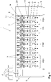
- FIG 1 shows a schematic front view of a spinning machine 1 in an overview.
- the spinning machine 1 is designed as an automatic or at least semi-automatic spinning machine 1 and has a Variety of similar, juxtaposed jobs 2, which are arranged between two frames 9.
- Each of the work stations 2 has a feed device 4 for a fiber material 7, which in the case of an open-end rotor spinning machine is a feed roller 16 (see figure 2 ) and an opening roller 12 (see figure 2 ) contains.
- the feed device 4 contains a drafting system (not shown).
- each of the work stations 2 has a spinning device 3 for producing a yarn 5 , a drawing-off device 11 for drawing off the yarn 5 and a winding device 19 for winding the yarn 5 produced onto a bobbin 6 held in a bobbin holder 17 .
- the jobs 2 are designed as at least partially self-sufficient jobs.
- the work stations 2 have at least one individually drivable spinning element, for example a spinning rotor 10 (see Fig. figure 2 ), an air spinning nozzle or a spindle with a ring traveler, so that the individual work stations 2 can also be operated independently of the other work stations 2 of the spinning machine 1.
- the workstations 2 can independently rectify at least some of the faults occurring during operation, at least the piecing after a yarn break or a clearer cut, without the need for an operating robot or the intervention of an operator.
- a display element 20 can also be provided at each of the work stations 2 to display various information relating to the work stations 2 .
- the spinning machine 1 also has a machine control 14 which controls at least the central and higher-level processes on the spinning machine 1 .
- machine control 14 controls at least the central and higher-level processes on the spinning machine 1 .
- work station controls 13 may be provided, which interact with the machine control 14 and possibly other control devices of the spinning machine 1.
- FIG 2 shows a work station 2 of such a spinning machine 1 in a schematic side view.
- the spinning machine 1 is designed here as an open-end rotor spinning machine and therefore has a feed roller 16 and an opening roller 12 as the feed device and a spinning rotor 10 as the spinning element of the spinning device 3 .
- the spinning rotor 10 be driven by means of a single drive 21, but also the other working elements of work station 2, such as the feed roller 16, the opening roller 12, the take-off device 11 and the winding device 19, are driven by means of a single drive 21.
- production groups PG are defined on such a spinning machine at the beginning of production when the machine starts or at the beginning of a specific shift or also during a specific shift to carry out a lot change. Become the production groups PG then assigned to the jobs 2, which are to produce the respective yarn lot. It is also possible to carry out a so-called flying batch change. A batch change from an old yarn batch that is still up-to-date to a new yarn batch can also be carried out at a single workstation 2 in such spinning machines 1 with at least partially self-sufficient workstations 2, without having to wait for the end of the batch to be reached at the other workstations 2 belonging to the same production group PG would have to.
- the jobs 2 are assigned to a new production group PG. This can be done in advance as part of production planning or only after the end of an old yarn lot has been reached. Work station 2 is first stopped when the end of the batch is reached. For the batch change, work station 2 must then be assigned to the new production group in terms of control technology and, if necessary, also converted, e.g. equipped with new spinning means and a different fiber material 7 or supplied with different empty tubes.
- the spinning means include, for example, spinning elements such as the spinning rotor 10, draw-off nozzles, twisting elements or other elements influencing the yarn quality.
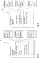
- shift reports 8 are created at the spinning machines 1. If the spinning machine 1 can produce several yarn lots in parallel and several production groups PG are set up during one shift, such a shift report 8 is created for each production group PG.
- the shift report 8 contains data on the start of the shift, the end of the shift and, if applicable, a shift number for the clear identification of the shift. Furthermore, production-related information such as the yarn lot, the amount of yarn produced 5 in [kg] and/or in [m] and the efficiency are contained in the shift reports 8 . Individual events that influence the efficiency, such as the above-mentioned yarn breaks, clearer cuts, the running out of the fiber material 7 and other operating requests from the work stations 2 are preferably also recorded, and are therefore shown in dashed lines. This data is presented as total values for all jobs 2 and the entire shift. The shift report 8 therefore also contains the number and job numbers of the jobs 2 belonging to a production group PG.
- the shift reports 8 can, for example, as in figure 1 shown, can be accessed via the machine control 14. It is optional and therefore also possible to call up a job report 18 for each individual job 2 , which contains the specified data and the times the respective job 2 belonged to the production group PG broken down for each job 2 . This is in the right pane figure 3 shown schematically.
- the present invention therefore proposes, in addition to the production groups PG, a free group FG (see 1 ) and to assign all jobs 2, which are currently not intended for yarn production and therefore do not have to be assigned to any of the production groups PG, to the free group FG.
- a shift report 8 is also created for the Freiner FG.
- Such a shift report 8 of a free group FG is shown schematically in 4 shown.
- the free group FG is defined in the same way as the production groups PG, but no lot data has to be assigned to it.
- the shift report 8 for the free group FG only contains data on the start of the shift, the end of the shift and the total number of jobs 2 assigned to the free group FG within this shift. Due to the definition of the free group FG, it is no longer necessary to list all jobs 2 in one assigned to the production groups PG. Instead, jobs 2 that are not assigned to any production groups PG are automatically assigned to the free group FG by the machine controller 14 .
- Analogously to shift report 8 for the production groups PG can optionally also be called up in the shift report 8 for the free group FG job reports 18, which contain data on the exact times when the respective job 2 belonged to the free group FG.
- the free group FG like the production groups PG, is not a constantly defined group over the entire shift, but it is possible that during a shift work stations 2 join a production group PG or the free group FG or leave them again.
- the shift report 8 can also contain the reasons for belonging to the free group FG, in order to to enable better evaluation of the data. For example, it would be conceivable to show separately the number and job numbers of jobs 2 that were not assigned to any production group PG. It is also possible to separately record the number and job numbers of jobs 2 that are at least temporarily switched off and/or the number and job numbers of defective jobs 2 . Further reasons for belonging to the free group FG can be waiting times for the start of a new yarn lot after the spinning machine 1 has started, waiting times for the start of a lot in connection with a lot change or also waiting times until a new production group PG is assigned in connection with a lot change. These waiting times can be collected or individually broken down and displayed. Optionally and therefore shown in dashed lines, the reasons for belonging to the Freioli FG can also be recorded for each job 2 and shown in the job reports 18 .
- the reference point in time for the assignment of a work station 2 to the free group FG in connection with a lot change is preferably the point in time at which the last bobbin 6 of an old yarn lot is removed from the bobbin holder 17.
- the relevant lot remains Work station 2 is assigned to its production group PG and the waiting times of this spinning station, eg for a spinning agent or fiber material exchange, are recorded within the old production group PG.
- the waiting times are already added to the new production group PG if the relevant job 2 is assigned directly to a new, already running production group PG.
- job 2 is assigned to the free group FG and the waiting times are recorded within the free group FG.
- the lot-related shift reports 8 also reflect the production data of the jobs 2 of a production group PG much more precisely, since these are not falsified by unproductive jobs 2 which are only assigned to the production group PG for formal reasons.
- a theoretical production capacity of the spinning machine 1 can also be determined in this way and optimization measures for the operation of the spinning machine 1 can be determined therefrom. If the reasons for the assignment to the free group FG are also recorded and presented in shift report 8 of the free group FG, optimization measures for a lot change can also be derived from this, for example.
- lot reports 18 in addition to the previously usual shift reports 8 .
- the lot reports 18 cover the entire production period of a yarn lot, which can also extend over several weeks and numerous shifts. Shift reports 8 are often stored on spinning machines 1 only for a specific period of time, or only a certain number of shift reports 8 are stored for capacity reasons.
- the now proposed game reports 18, on the other hand, enable the identification of certain events at the workplaces 2 over a longer period of time and thus allow more extensive evaluations.
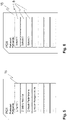
- the figure 5 shows a first version of a lot report 15, which contains data about the lot start and the lot end as well as production data of the work stations 2. These are only recorded and displayed as cumulative values over the entire duration of the game.
- the batch reports 15 can contain the quantity of yarn 5 produced, the duration of downtimes, possibly differentiated according to reasons for the downtimes, or the number of specific events at the work stations 2, such as yarn breakages.
- the events and times can also be recorded and displayed in a further breakdown.
- lot report 15 only provides information about the production data for the entire yarn lot, but does not allow any conclusions to be drawn about the chronological occurrence of the individual events or the recorded times.
- figure 6 shows, however, another version of a game report 15, which in addition or as an alternative to the total values of figure 5 also includes the individual shift reports 8 per yarn lot.
- a lot report 15 allows the chronological assignment of specific production data to a specific shift. Events that only occurred in certain shifts can also be recorded in this way and their cause can be eliminated if necessary.
- a preparation report (not shown) can also be included, for example, which contains data about the set-up of the yarn lot. Since such a batch report 15 containing the individual shift reports 8 for each batch of yarn is very extensive, it can also be advantageous to create the batch report 15 at intervals with respective transmission to a higher-level control system. If the spinning machine 1 is connected to such a control system, it continues to be so conceivable to create shift reports 8 and batch reports 15 directly there.
Landscapes
- Engineering & Computer Science (AREA)
- Mechanical Engineering (AREA)
- Textile Engineering (AREA)
- Spinning Or Twisting Of Yarns (AREA)
Applications Claiming Priority (1)
| Application Number | Priority Date | Filing Date | Title |
|---|---|---|---|
| DE102020134252.7A DE102020134252A1 (de) | 2020-12-18 | 2020-12-18 | Verfahren zum Betreiben einer teil- oder vollautomatischen Spinnmaschine, insbesondere einer Offenend-Rotorspinnmaschine, sowie Spinnmaschine |
Publications (1)
| Publication Number | Publication Date |
|---|---|
| EP4101958A1 true EP4101958A1 (fr) | 2022-12-14 |
Family
ID=81847067
Family Applications (1)
| Application Number | Title | Priority Date | Filing Date |
|---|---|---|---|
| EP21213545.3A Withdrawn EP4101958A1 (fr) | 2020-12-18 | 2021-12-09 | Procédé de fonctionnement d'un métier à filer partiellement ou entièrement automatique, en particulier d'un métier à filer à rotor à bout libre, ainsi que métier à filer |
Country Status (3)
| Country | Link |
|---|---|
| EP (1) | EP4101958A1 (fr) |
| CN (1) | CN114645341A (fr) |
| DE (1) | DE102020134252A1 (fr) |
Citations (3)
| Publication number | Priority date | Publication date | Assignee | Title |
|---|---|---|---|---|
| DE19505023A1 (de) * | 1995-02-15 | 1996-08-22 | Schlafhorst & Co W | Textilmaschine mit einer zentralen Steuereinrichtung und dezentralen Steuereinrichtungen an den Arbeitsstellen |
| EP1460016A1 (fr) * | 2003-03-17 | 2004-09-22 | Murata Kikai Kabushiki Kaisha | Bobinoir automatique |
| EP2107141A2 (fr) * | 2008-03-31 | 2009-10-07 | Murata Machinery Ltd. | Appareil de filature |
Family Cites Families (3)
| Publication number | Priority date | Publication date | Assignee | Title |
|---|---|---|---|---|
| DE10153457B4 (de) | 2001-10-30 | 2015-07-16 | Rieter Ingolstadt Gmbh | Textilmaschine mit einer Vielzahl von Bearbeitungsstellen und Kommunikationsverfahren hierfür |
| DE102004016796B4 (de) | 2004-04-06 | 2013-02-07 | Rieter Ingolstadt Gmbh | Offenend-Spinnmaschine |
| DE102018121316A1 (de) | 2018-08-31 | 2020-03-05 | Maschinenfabrik Rieter Ag | Textilmaschine und Verfahren zum Steuern einer Textilmaschine |
-
2020
- 2020-12-18 DE DE102020134252.7A patent/DE102020134252A1/de active Pending
-
2021
- 2021-12-03 CN CN202111464301.6A patent/CN114645341A/zh active Pending
- 2021-12-09 EP EP21213545.3A patent/EP4101958A1/fr not_active Withdrawn
Patent Citations (3)
| Publication number | Priority date | Publication date | Assignee | Title |
|---|---|---|---|---|
| DE19505023A1 (de) * | 1995-02-15 | 1996-08-22 | Schlafhorst & Co W | Textilmaschine mit einer zentralen Steuereinrichtung und dezentralen Steuereinrichtungen an den Arbeitsstellen |
| EP1460016A1 (fr) * | 2003-03-17 | 2004-09-22 | Murata Kikai Kabushiki Kaisha | Bobinoir automatique |
| EP2107141A2 (fr) * | 2008-03-31 | 2009-10-07 | Murata Machinery Ltd. | Appareil de filature |
Also Published As
| Publication number | Publication date |
|---|---|
| CN114645341A (zh) | 2022-06-21 |
| DE102020134252A1 (de) | 2022-06-23 |
Similar Documents
| Publication | Publication Date | Title |
|---|---|---|
| EP3760772B1 (fr) | Optimisation du fonctionnement d'un métier à filer | |
| EP3802927B1 (fr) | Ligne de filature à anneau et son procédé de fonctionnement | |
| EP3144418B1 (fr) | Procede d'adaptation d'une conception usine concernant une fabrication de lot de fil d'un metier a tisser a rotor a extremite ouverte | |
| EP3757264B1 (fr) | Procédé de fonctionnement d'un métier à filer à filetage croisé partiellement ou entièrement automatique | |
| DE102016014976A1 (de) | Verfahren und Vorrichtung zum Schmelzspinnen eines Fadens | |
| EP0731195B1 (fr) | Dispositif et procédé pour l'entretien des métiers à filer | |
| EP3642401B1 (fr) | Procédé et dispositif de filage par fusion de fils synthétiques | |
| DE102015118987A1 (de) | Verfahren zum Betreiben einer Spinnmaschine mit einer vollautomatischen Anspinnvorrichtung sowie Spinnmaschine mit einer vollautomatischen Anspinnvorrichtung | |
| EP3604642A1 (fr) | Procédé de fonctionnement d'une machine textile et machine textile | |
| EP4015684A1 (fr) | Procédé de fonctionnement d'un métier à filer partiellement ou entièrement automatique, en particulier d'un métier à filer à rotor à bouts ouverts, ainsi que métier à filer | |
| EP4101958A1 (fr) | Procédé de fonctionnement d'un métier à filer partiellement ou entièrement automatique, en particulier d'un métier à filer à rotor à bout libre, ainsi que métier à filer | |
| DE2944219A1 (de) | Verfahren zum kontrollieren, einstellen und steuern von arbeits-, insbesondere spinneinheiten bzw. diese aufweisenden maschinen und vorrichtung zum durchfuehren dieses verfahrens | |
| EP1526195A2 (fr) | Machine textile et méthode pour améliorer un processus de production de cette machine | |
| EP4215655A1 (fr) | Procédé de fonctionnement d'un poste de filage d'un métier à filer à rotor et métier à filer à rotor | |
| EP3882383A1 (fr) | Procédé de fonctionnement d'une machine textile et machine textile | |
| EP3901336A1 (fr) | Métier à filer doté d'une pluralité de postes de travail les uns à côté des autres, ainsi que procédé de fonctionnement d'un métier à filer doté d'une pluralité de postes de travail les uns à côté des autres | |
| DE3902179A1 (de) | Verfahren und vorrichtung zum selbsttaetigen ausfuehren von bedienfaellen an mindestens einer ringspinn- oder -zwirnmaschine | |
| DE102004044551B4 (de) | Verfahren zum Betrieb einer Spinnmaschine sowie Spinnmaschine zur Ausführung dieses Verfahrens | |
| EP3875647B1 (fr) | Procédé de fonctionnement d'un métier à filer, ainsi que métier à filer | |
| DE4440206A1 (de) | Verfahren zum Beurteilen der Faserbandqualität in einer Textilmaschine | |
| EP2576877B1 (fr) | Dispositif de surveillance sur une machine textile | |
| DE102022129722A1 (de) | Verfahren zum Betreiben einer Spinnstelle einer Rotorspinnmaschine sowie Rotorspinnmaschine | |
| WO2024078939A1 (fr) | Procédé pour faire fonctionner un ensemble métier à filer comprenant au moins un métier à filer et ensemble métier à filer comprenant au moins un métier à filer | |
| DE102020129172A1 (de) | Verfahren zum Warten wenigstens einer Arbeitsstelle einer Spinnmaschine | |
| CH469620A (de) | Verfahren zur Ueberwachung der Spulstellen einer automatischen Spulmaschine |
Legal Events
| Date | Code | Title | Description |
|---|---|---|---|
| PUAI | Public reference made under article 153(3) epc to a published international application that has entered the european phase |
Free format text: ORIGINAL CODE: 0009012 |
|
| STAA | Information on the status of an ep patent application or granted ep patent |
Free format text: STATUS: THE APPLICATION HAS BEEN PUBLISHED |
|
| AK | Designated contracting states |
Kind code of ref document: A1 Designated state(s): AL AT BE BG CH CY CZ DE DK EE ES FI FR GB GR HR HU IE IS IT LI LT LU LV MC MK MT NL NO PL PT RO RS SE SI SK SM TR |
|
| STAA | Information on the status of an ep patent application or granted ep patent |
Free format text: STATUS: REQUEST FOR EXAMINATION WAS MADE |
|
| 17P | Request for examination filed |
Effective date: 20230130 |
|
| RBV | Designated contracting states (corrected) |
Designated state(s): AL AT BE BG CH CY CZ DE DK EE ES FI FR GB GR HR HU IE IS IT LI LT LU LV MC MK MT NL NO PL PT RO RS SE SI SK SM TR |
|
| GRAP | Despatch of communication of intention to grant a patent |
Free format text: ORIGINAL CODE: EPIDOSNIGR1 |
|
| STAA | Information on the status of an ep patent application or granted ep patent |
Free format text: STATUS: GRANT OF PATENT IS INTENDED |
|
| INTG | Intention to grant announced |
Effective date: 20230613 |
|
| STAA | Information on the status of an ep patent application or granted ep patent |
Free format text: STATUS: THE APPLICATION IS DEEMED TO BE WITHDRAWN |
|
| 18D | Application deemed to be withdrawn |
Effective date: 20231024 |