EP4101558A1 - Procédé de fabrication d'un dôme d'aérosol - Google Patents
Procédé de fabrication d'un dôme d'aérosol Download PDFInfo
- Publication number
- EP4101558A1 EP4101558A1 EP21178792.4A EP21178792A EP4101558A1 EP 4101558 A1 EP4101558 A1 EP 4101558A1 EP 21178792 A EP21178792 A EP 21178792A EP 4101558 A1 EP4101558 A1 EP 4101558A1
- Authority
- EP
- European Patent Office
- Prior art keywords
- stage
- area
- range
- flange
- edge
- Prior art date
- Legal status (The legal status is an assumption and is not a legal conclusion. Google has not performed a legal analysis and makes no representation as to the accuracy of the status listed.)
- Pending
Links
Images


Classifications
-
- B—PERFORMING OPERATIONS; TRANSPORTING
- B21—MECHANICAL METAL-WORKING WITHOUT ESSENTIALLY REMOVING MATERIAL; PUNCHING METAL
- B21D—WORKING OR PROCESSING OF SHEET METAL OR METAL TUBES, RODS OR PROFILES WITHOUT ESSENTIALLY REMOVING MATERIAL; PUNCHING METAL
- B21D51/00—Making hollow objects
- B21D51/02—Making hollow objects characterised by the structure of the objects
- B21D51/10—Making hollow objects characterised by the structure of the objects conically or cylindrically shaped objects
-
- B—PERFORMING OPERATIONS; TRANSPORTING
- B21—MECHANICAL METAL-WORKING WITHOUT ESSENTIALLY REMOVING MATERIAL; PUNCHING METAL
- B21D—WORKING OR PROCESSING OF SHEET METAL OR METAL TUBES, RODS OR PROFILES WITHOUT ESSENTIALLY REMOVING MATERIAL; PUNCHING METAL
- B21D51/00—Making hollow objects
- B21D51/16—Making hollow objects characterised by the use of the objects
- B21D51/24—Making hollow objects characterised by the use of the objects high-pressure containers, e.g. boilers, bottles
-
- B—PERFORMING OPERATIONS; TRANSPORTING
- B21—MECHANICAL METAL-WORKING WITHOUT ESSENTIALLY REMOVING MATERIAL; PUNCHING METAL
- B21D—WORKING OR PROCESSING OF SHEET METAL OR METAL TUBES, RODS OR PROFILES WITHOUT ESSENTIALLY REMOVING MATERIAL; PUNCHING METAL
- B21D22/00—Shaping without cutting, by stamping, spinning, or deep-drawing
- B21D22/20—Deep-drawing
-
- B—PERFORMING OPERATIONS; TRANSPORTING
- B21—MECHANICAL METAL-WORKING WITHOUT ESSENTIALLY REMOVING MATERIAL; PUNCHING METAL
- B21D—WORKING OR PROCESSING OF SHEET METAL OR METAL TUBES, RODS OR PROFILES WITHOUT ESSENTIALLY REMOVING MATERIAL; PUNCHING METAL
- B21D51/00—Making hollow objects
- B21D51/16—Making hollow objects characterised by the use of the objects
- B21D51/26—Making hollow objects characterised by the use of the objects cans or tins; Closing same in a permanent manner
- B21D51/2615—Edge treatment of cans or tins
- B21D51/2623—Curling
Definitions
- the present invention relates to a method for producing an aerosol dome and an aerosol dome produced using such a method.
- Pot-shaped metal objects can be formed from a flat section of sheet metal in a cold forming process. This typically happens after a stamping process or combined with one in a single forming step (deep drawing), in which the finished component is given its final shape.
- Such processes are used, for example, for the production of pots, spray cans, components in the automotive industry or in the furniture industry, for food packaging, etc.
- Aluminum and tinplate in particular are used as materials.
- the forming process must be carried out carefully in order to avoid the formation of cracks, creases, etc. and thus rejects or insufficient quality. This applies above all to the formation of conical wall areas because, in contrast to the formation of axially cylindrical wall areas, guidance in the tool is not guaranteed to the same extent in such cases.
- US4914937 proposes a method of forming a tapered container by first drawing the container to a partial length having first and second straight sidewall sections interconnected by a transition section and then drawing material from the transition section to substantially its final length length and its tapered state.
- the method also optionally includes a second overlength redraw and a bottom profiling step in which the coated portion is used to form the profile.
- EP-A-0310726 discloses a method of drawing with a cylindrical punch and frusto-conical die. According to the invention, the blank is subjected to one (or more) drawing operations between a frustoconical die and a cylindrical punch, the pressure of the clamping means being relieved so that the metal, as it deforms, conforms to the shape of the die. Application at Manufacture of can bodies from "double reduced" sheet metal.
- EP-A-3702061 describes a method for producing a component from sheet metal with an at least partially curved or linearly conical area from a pot-shaped blank with a substantially cylindrical wall section.
- the method is characterized in that it comprises at least the following steps: a step train, in which the cylindrical edge section of the blank is formed between a drawing die and a drawing punch guided in a blank holder so as to be displaceable, into a stepped area with two cylinder sections; at least one subsequent cone curve, in which at least the stepped area is formed into a curved or linearly conical component section between two tools.
- EP-A-1372880 and EP-A-3691810 describe processes for the production of rolled edges.
- EP-A-3691810 is a method for producing a rolled edge from a cylindrical edge section of a pipe, in which a starting area of the edge section is rolled by a positively controlled tool. A flanging tool then moves into the rolled edge area and flangs the rolled edge area into a roll.
- the method is characterized in that the starting area of the edge section is flanged at an angle in the range of 75-105 degrees from the axial direction into a substantially radially circumferential flange by the tool, which comprises a bending punch and a counterholder.
- the object of the present invention is to provide a method for producing an aerosol dome that makes it possible to produce a dome that is as stable as possible with as little material as possible (low material thickness) without damaging a lacquer layer or polymer layer on the material.
- the subject matter of the present invention is accordingly a method according to claim 1 or a use according to claim 14 and an aerosol dome according to claim 15.
- the present invention relates to a method for producing an aerosol dome with a dome area with a rolled edge arranged on an upper passage opening and adjoining the top side and with a flange area bordering on the underside with a fold-over.
- an intermediate stage is provided from a lacquer-coated or polymer-coated blank in one or more stages, which has the upper through opening, followed downwards by a preferably substantially cylindrical neck section, further followed by the dome area, which is followed by a circumferential straight flange.
- This intermediate stage is processed in a processing stage in which only the eversion in one Deep drawing process is formed.
- Such a method is preferably further characterized in that the intermediate stage has an outwardly directed collar and/or an outwardly curved corrugation at the transition from the dome area to the neck area.
- the processing stage for producing the inversion is preferably followed directly or indirectly by at least one further stage in which a rolled edge is formed from the neck section.
- the processing stage for producing the eversion is followed directly or indirectly by at least one further stage in which a preliminary stage or the final edge curl is produced from the remaining flange, this further stage preferably being combined if only one preliminary stage is formed with a stage in which the neck portion is formed into an edge curl, and then preferably this stage is followed by a further stage in which the edge curl is formed. No further steps then preferably follow.
- the paint-coated blank is preferably presented in the form of a pot with a circumferential flange, a rounded area and a bottom but without a neck area, and in at least a first stage this blank is cut to the required part height H (typically in the range of 10-40 mm) before a rolled edge is produced formed with an axial neck area, and preferably further in this first step the radius at the transition area between the flange and the rounded area is reduced, preferably to a radius in the range of 0.2-1.0 mm, particularly preferably in the range of 0.3-0.6 mm.
- the neck area can be shaped further in at least one, preferably in two further stages, a second stage and a third stage, in particular the radius of the area between the axial neck area and the radial base can be reduced, preferably to a sharp edge with a radius in the range of 0.05-0.6 mm, particularly preferably in the range of 0.1-0.2 mm.
- the bottom which may have been prepared with a scratch, is guided out of the tool as a bowl, forming the upper through-opening, or punched out to form the upper through-opening, and preferably subsequently in a sixth stage the peripheral edge thus formed is folded over to form a collar, with the fifth step and the sixth step also preferably being carried out after the two further steps as set out above.
- the transition area between the base and the neck area can also be scored in order to prepare for the removal of the base.
- a further preferred embodiment is characterized in that to produce the rolled edge from a cylindrical edge section of the neck area, in a first step, preferably in the fifth stage as set out above, an initial zone of the edge section is folded over to form the collar using a positively controlled tool and in a second step step, preferably in the further stage as set out above, a flanging die then moves into the folded edge section and flangs it into a roll, with the first step turning the initial zone of the edge section by an angle in the range of 75- 105°, preferably in the range of 80-100°, or in the range of 85-95°, from the axial direction to a substantially radial circumferential flange.
- the bending radius between the circumferential flange and the adjoining axial section is preferably smaller than twice the material thickness of the cylindrical edge section, preferably the bending radius is in the range of 0.5-1.5 times, particularly preferably in the range of 0.75-1.25 times the material thickness of the cylindrical edge section.
- the radial length of the flange is also preferably in the range of 2-5 times, preferably in the range of 3-4 times the material thickness of the cylindrical edge section.
- the material of the blank is preferably provided with a dense layer of lacquer on both sides or at least on the future upper side (outer surface 7).
- the paint can be applied directly to the metal or via an additional adhesion promoter layer. It is preferably a polyester paint, an acrylate-based system or a methacrylate-based system or a polyurethane paint. Such a paint can be water-based or solvent-based, and it can be cross-linked. The paint is preferably applied without VOC.
- the blank can also be provided with a dense polymer layer or plastic layer, or with several such layers. Then there are usually additional adhesion promoter layers in between the metal and the at least one plastic layer.
- the plastic layer can consist of polyethylene terephthalate (PET) or polypropylene (PP) or polyethylene (PE), or a mixture of such systems.
- PET polyethylene terephthalate
- PP polypropylene
- PE polyethylene
- the plastic layer can also contain the usual additives (especially Plasticizers, fillers) and, above all, optionally dyes or pigments in the usual proportions.
- the thickness of such a paint layer or plastic layer is typically in the range of 5-40 ⁇ m (including any adhesion promoter layer that may be present).
- the material thickness of the blank is typically in the range of 0.1-1 mm, preferably in the range of 0.15-0.4 mm, particularly preferably in the range of 0.18-0.34 mm.
- the material of the blank is preferably sheet steel, preferably tinplate. However, aluminum is also possible.
- the material of the blank (R) is preferably sheet steel particularly preferably with a yield point, determined according to DIN EN 10002-1:2001, of at least 500 MPa, preferably at least 520 MPa, particularly preferably at least 550 MPa, and/or with a tensile strength, determined according to DIN EN 10002-1:2001, of at least 500 MPa, preferably at least 550 MPa, particularly preferably at least 575 MPa.
- the material of the blank (R) is sheet steel, preferably TH520 type tinplate, material number 1.0384; TH550. material number 1.0373; TH580, material number 1.0382; TH620, material number 1.0374, or the corresponding TS types, each according to DIN EN 10202: 2001, and/or DR8, DR8, DR8.5, or DR9, each according to AISI/ASTM 623.
- the present invention further relates to the use of such a method for producing an aerosol dome for a spray can.
- the present invention also relates to a tool for carrying out such a method.
- the present invention relates to an aerosol dome for a spray can produced by a method as set out above or in a tool as set out above.
- a pot-shaped blank R produced in a previous stamping and forming process is supplied to the process as shown by arrow 21 .
- this pot-shaped blank R which is typically first punched out of a raw material supplied in strip form and then deep-drawn into a cup, which can be done in one or two steps, to be carried out as the first step within the scope of the sequence of steps described here .
- This blank R shown in a), has a peripheral flange 15 which transitions from an initially cylindrical area 53 into a rounded area 17 and which has a closed bottom 18 .
- this blank R is subjected to a first drawing Z1, with a punch being inserted into the interior of the blank and the blank being pressed against a die.
- the cylindrical area 53 and parts of the rounded area 17 are formed into a dome area 5
- parts of the rounded area 17 and the bottom 18 are formed into a neck section 14, which follows the dome area via a transition 20.
- the base 18 is reduced in diameter and a curve 19 is set at the transition from the base 18 to the neck portion.
- the flange 15 essentially remains in place and the component has not yet reached its final height, this will only be adjusted in subsequent steps.
- a step RP represented by the arrow 23 the edge is then cropped, i. H. the radial length of the flange 15 is adjusted to the desired value, this step takes place here within the framework of stations S2 and S3 (one of which is an empty station), this leads to the component according to c).
- this is Component subjected to a second pulling Z2, which in turn is retracted into the interior with a punch and the component is pressed against a die. This results in the component shown in d).
- the dome area 5 is reshaped and increased, and the neck section 14 is lengthened and its radius reduced.
- this component is subjected to a third drawing Z3, with a punch again being inserted into the interior and the component being pressed against a die. This results in the component shown in e).
- this step essentially only the previously round area 19 is formed into a sharp edge 31 at the transition from the neck area 14 to the base 18 .
- this component is subjected to scoring Ri, i. H. in the area of the transition 31 between the base 18 and the neck area 14, a circumferential score is produced, the function of which is as follows in further processing: the base is prepared in order to be torn away in the next station and pulled out of the tool as a bowl. This results in the component shown in f).
- this component is subjected to several steps U at the same time.
- an inversion 3 is produced from parts of the dome area 5 .
- This inversion goes over a vertical section 9 into the flange 15 and radially inwards over an adjoining area 8 into the dome area 5.
- the thickening of the material (upsetting) resulting from this type of forming places a great deal of stress on the coating, which can lead to spalling the shift can lead to.
- higher pressures can be withstood when installed in a can.
- a slight outwardly directed wave 13 is formed in the dome area 5 in this step, which adjoins the neck portion 14 .
- the base that was prepared in station 5 is taken out of the tool as a cup, resulting in a through opening 32 at the top and a free straight edge 16 of the cylindrical section 14, and the component height is adjusted. This results in the component shown in g).
- this component is subjected to a tilting A.
- an initial zone of the edge section 16 is folded over by a tool that is usually inevitably controlled and only then, in the context of the next stage S9, in a second step, a flanging die is moved into the folded edge section and this is flanged into a roll 2 .
- the initial zone of the edge section 16 is formed by a folding stamp and counter-holder tooling is folded over at an angle in the range 75-105 degrees from the axial direction to a substantially radial circumferential flange 12. This results in the component shown in h).
- the rolled edge 2 is formed on the one hand and the radial peripheral edge of the flange 15 is folded over in a preliminary stage 11 on the other hand, so that a horizontal flange section 10 remains. This results in the component shown in i).
- the flange 15 is turned inside out. However, this is now to be deep-drawn using a process that is gentler on the material.
- the outer area of the dome area is turned inside out to form the inversion 3 and the flange is thus prepared for the subsequent station S9.
- this type of forming leads to irregular damage to the paint on the lid.
- stage S7 After scoring Ri during inversion U, in which the part is lifted apart from the forming of the shaft 13 and the cover and a material shift takes place.
- the height of the part and the flange diameter required for beading are set here. Since the material has to be free in a certain area of the forming and is not held correctly, there are different tensile, compressive and bending stresses on the sheet metal, which can result in damage to the paintwork.
- Damage to the paintwork is avoided by a new forming step and a different sequence of stages.
- a more material-friendly forming is carried out in the form of drawing. First the height of the part is set (see Drag Z1 and Set Height in S1 in 2 ). After setting the height, the drawing continues, and then later in the tool (S9 in 2 ) to finish pulling the flange 15. There is also the advantage that the contact point of the critical section with the tool is pushed backwards and the part therefore hits the press-in sleeve less frequently. With the new sequence of steps, one station is used more than before.
- a method according to the invention is in 2 presented in a sequence of steps.
- a pot-shaped blank R produced in a previous stamping and forming process is supplied to the process as shown by arrow 21 . It is also possible that the production of this pot-shaped blank R, which is typically first punched out of a raw material supplied in strip form and then deep-drawn into a cup, which can be done in one or two steps, within the scope of those described here Carry out the sequence of steps as the first step.
- This blank R shown in a), has a peripheral flange 15 which, via a transition 38, transitions from an initially almost cylindrical area 53 to a rounded area 17, and which has a closed bottom 18.
- the material of the blank R is sheet steel, namely tinplate, with a yield point (determined according to EN 10202:2001, in particular Chapter 8.2 and the measurement method according to DIN EN 10002-1:2001) of at least 550 MPa. It has a tensile strength (determined according to EN 10202:2001, in particular Chapter 8.2 and the measuring method according to DIN EN 10002-1:2001) of at least 575 MPa.
- the material is TH520 (material number 1.0384), TH550 (material number 1.0373), TH580 (material number 1.0382), TH620 (material number 1.0374) tinplate, or the corresponding TS types, each formulated according to DIN EN 10202: 2001 alternatively of type DR8, DR8, DR8.5, or DR9, each according to AISI/ASTM 623.
- TH520 material number 1.0384
- TH550 material number 1.0373
- TH580 material number 1.0382
- TH620 material number 1.0374
- the material is provided with a layer of lacquer on both sides or at least on the future upper side (outer surface 7), a polyester lacquer was used here.
- the blank can also be provided with a polymer layer or plastic layer, or with several such layers.
- the commercial system Protact ® is possible.
- this blank R is subjected to a first drawing Z1, with a punch being inserted into the interior of the blank and the blank being pressed against a die (cf. also 3 ).
- the height HE is adjusted in this process.
- the essentially cylindrical area 53 and parts of the rounded area 17 are formed into a dome area 5, as well as parts of the rounded area 17 and the base 18 forming a neck section 14, which follows the dome area via a transition 20.
- the base 18 is reduced in diameter and a curve 19 is set at the transition from the base 18 to the neck portion.
- the flange 15 essentially remains and the component is already given its final height here.
- the transition between the flange 15 and the dome area 5 is formed into a sharp edge 37, typically with a radius in the range of at least 0.35 mm.
- this component is subjected to a second drawing Z2, with a punch again being inserted into the interior and the component being pressed against a die. out of it results in the component shown in c).
- the dome area 5 is further formed and the radius of the neck section 14 is reduced.
- this component is subjected to a third drawing Z3 in the third station S3, with a punch again being inserted into the interior and the component being pressed against a die. This results in the component shown in d).
- this step essentially only the previously round area 19 is formed into a sharp edge 31 at the transition from the neck area 14 to the base 18 .
- this component is subjected to scoring Ri, i. H. in the area of transition 31 between base 18 and neck 14, a circumferential score is created, the function of which is as follows in further processing: the base is prepared so that it can be torn away at the next station and pulled out of the tool as a bowl. This results in the component shown in e).
- this component is subjected to a tilting A.
- an initial zone of the edge section 16 is folded over by a tool that is usually automatically controlled and only then in a further stage S10 in a second step is a flanging die inserted into the folded edge section and this is flanged to form a roll 2 .
- the initial zone of the edge portion 16 is folded over by a tool comprising a folding punch and anvil at an angle in the range of 75-105 degrees from the axial direction to a substantially radial circumferential flange 12 . This results in the component shown in g).
- the edge is then trimmed, i. H. the radial length of the flange 15 is adjusted to the desired value, this step takes place here within the framework of stations S7 and S8 (one of which is an empty station), this leads to the component according to h).
- This component is now so far finished in terms of shaping that only the final steps on the flange 15 and on the neck area 14 have to be carried out, and the component can be optimally guided in all steps up to this point.
- the step of turning inside out becomes all alone in the next stage carried out and with a component in which all forming and stamping have already been carried out, insofar as they can be carried out at all before this step without causing problems in relation to the process management.
- the bottom 18 has already been punched out and the collar 12 has been formed, and the rotating shaft 13 is also already in place, and the final component height, apart from the rolling of the rolled edge 2, has been created.
- this component is now only subjected to the step FZ.
- an inversion 3 is produced from parts of the dome area 5, and it is possible to optimally hold and guide the material. This inversion goes over a vertical section 9 into the flange 15 and radially inwards in the adjoining area 8 into the dome area 5. This leads to the component according to i).
- the rolled edge 2 is formed for this component on the one hand and the radial peripheral edge of the flange 15 is folded over on the other hand in a preliminary stage 11 so that a horizontal flange section 10 remains. This results in the component shown in k).
- steps S1 and S9 are used here for forming the part of the flange.
- a comparison with the episode after 1 makes the differences in the flange area clear.
- stations S1-S8 the critical area for internal paintwork damage can be spared because large-area press-in sleeves can be used.
- the sequence of these steps between the stations S1 and S8 can also be chosen differently than in 2 shown. Large-area push-in sleeves are also used in stations S10 and S11.
- FIG. 3 shows the tool of the first stage S1, where in a) the tool is shown at the beginning of the stroke and in b) the tool is shown at the end of the stroke.
- the component height is set at this stage and the transition area 37 between the flange 15 and the cylindrical or slightly conically converging area 53 is already brought into the final shape.
- the in Fig. 3 a) inserted blank R between a drawing die 39, which rests on the outer surface 7 of the rounded portion 17, and a blank holder 41, which rests on the inside 6, out.
- a drawing die 40 which is mounted on the inside of the blank holder 41, now moves into the bottom area 8 and thus forms the neck area 14 (cf Fig. 3 b) ).
- the guide sleeve 43 and the counter-holder 42 move from bottom to bottom Contact surface 55 of the drawing die, the sharp edge 37 being formed at the transition between the contact surface 55 and the rounded area 45 of the drawing die at the transition between the flange 15 and the dome area 5 .
- the process is also managed in such a way that the required component height H is set.
- the material in the critical dome area 5 is guided and supported at all times by the inner contact surface 44 of the blank holder 41 and the contact surface 45 of the drawing die 39, so that damage or overloading with resulting porosity of the lacquer layer can be avoided.
- the height is first set in combination with the first drag.
- the part rests on the flange 15 because the indentation sleeve is wider.
- the blank R is positioned via a hold-down device on the press-in sleeve 43 via the blank holder 41, which is positively fitted to the blank R.
- the material is drawn into the die 39 and the first train begins to form.
- the flange 15 is then placed down to the desired part height.
- the radius Ra is also formed here, which is typically in the range of at least 0.30 mm.
- the flange 15 is set and the volume of material required for drawing the flange is already in the right place.
- the upper area is then pulled further.
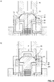
- Figure 12 shows the tool for forming the fold in S9, with a) showing the tool at the start of the stroke and b) showing the tool at the end of the stroke.
- the output component that is in Fig. 2 h) is shown, is held comprehensively and flatly here between a drawing punch 46 and a receptacle 51 in the dome area 5 .
- the flange 15 is guided between an upper blank holder 48 and drawing die 49 below.
- At the lower end of the drawing die there is a shaped piece 47 which serves as a shaping element for the drawing process 3 .
- a lifting sleeve or impression sleeve 50 is arranged between the bottom drawing die 49 and the receptacle 51 .
- the drawing punch 46 and the receptacle 51 move downwards in parallel and thereby clamp the material in the dome area 5.
- the blank holder 48 clamps the flange 15 on the drawing die 49 (this is rigid) and thus draws the offset (no inversion process , but deep-drawing), with the flange 15 withdrawing somewhat from the gap between the two counter-holders 48/49.
- the flange is prepared for drawing, it is only drawn into the die 49.
- the part is controlled by the drawing die 46 via the press-in sleeve 50 onto a spring-loaded, form-fitting receptacle 51 .
- a fold holder 48 prevents the Wrinkling during forming.
- the material on the flange 15 is drawn into the die. This forms the flange height as well as the flange diameter. In addition, the diameter for the lid holder in the body (can body) is drawn out through the die.
Priority Applications (2)
| Application Number | Priority Date | Filing Date | Title |
|---|---|---|---|
| EP21178792.4A EP4101558A1 (fr) | 2021-06-10 | 2021-06-10 | Procédé de fabrication d'un dôme d'aérosol |
| US17/836,346 US20220395887A1 (en) | 2021-06-10 | 2022-06-09 | Method for producing an aerosol dome |
Applications Claiming Priority (1)
| Application Number | Priority Date | Filing Date | Title |
|---|---|---|---|
| EP21178792.4A EP4101558A1 (fr) | 2021-06-10 | 2021-06-10 | Procédé de fabrication d'un dôme d'aérosol |
Publications (1)
| Publication Number | Publication Date |
|---|---|
| EP4101558A1 true EP4101558A1 (fr) | 2022-12-14 |
Family
ID=76392158
Family Applications (1)
| Application Number | Title | Priority Date | Filing Date |
|---|---|---|---|
| EP21178792.4A Pending EP4101558A1 (fr) | 2021-06-10 | 2021-06-10 | Procédé de fabrication d'un dôme d'aérosol |
Country Status (2)
| Country | Link |
|---|---|
| US (1) | US20220395887A1 (fr) |
| EP (1) | EP4101558A1 (fr) |
Citations (8)
| Publication number | Priority date | Publication date | Assignee | Title |
|---|---|---|---|---|
| DE2816860A1 (de) * | 1978-04-18 | 1979-10-25 | Styner & Bienz Ag | Verfahren zur herstellung eines aerosoltrichters |
| EP0310726A1 (fr) | 1986-09-17 | 1989-04-12 | Cmb Packaging S.A. | Procédé de fabrication de boîtes métalliques tronconiques et outillage pour la mise en oeuvre de ce procédé |
| US4914937A (en) | 1987-12-07 | 1990-04-10 | Redicon Corporation | Method for forming tall tapered containers |
| EP1372880A1 (fr) | 2001-04-06 | 2004-01-02 | Adval Tech Holding AG | Proc d pour r aliser un bord retourn |
| KR20090054683A (ko) * | 2007-11-27 | 2009-06-01 | 대성산업 주식회사 | 재충전 가스용기 제조방법 |
| WO2019068539A1 (fr) * | 2017-10-02 | 2019-04-11 | Adval Tech Holding Ag | Procédé pour réaliser un bord retourné |
| WO2019154743A1 (fr) * | 2018-02-06 | 2019-08-15 | Tata Steel Ijmuiden B.V. | Procédé et appareil de production d'un corps de boîte-boisson par étirage de parois |
| EP3702061A1 (fr) | 2019-03-01 | 2020-09-02 | Adval Tech Holding AG | Procédé de fabrication d'objets métalliques coniques |
-
2021
- 2021-06-10 EP EP21178792.4A patent/EP4101558A1/fr active Pending
-
2022
- 2022-06-09 US US17/836,346 patent/US20220395887A1/en active Pending
Patent Citations (9)
| Publication number | Priority date | Publication date | Assignee | Title |
|---|---|---|---|---|
| DE2816860A1 (de) * | 1978-04-18 | 1979-10-25 | Styner & Bienz Ag | Verfahren zur herstellung eines aerosoltrichters |
| EP0310726A1 (fr) | 1986-09-17 | 1989-04-12 | Cmb Packaging S.A. | Procédé de fabrication de boîtes métalliques tronconiques et outillage pour la mise en oeuvre de ce procédé |
| US4914937A (en) | 1987-12-07 | 1990-04-10 | Redicon Corporation | Method for forming tall tapered containers |
| EP1372880A1 (fr) | 2001-04-06 | 2004-01-02 | Adval Tech Holding AG | Proc d pour r aliser un bord retourn |
| KR20090054683A (ko) * | 2007-11-27 | 2009-06-01 | 대성산업 주식회사 | 재충전 가스용기 제조방법 |
| WO2019068539A1 (fr) * | 2017-10-02 | 2019-04-11 | Adval Tech Holding Ag | Procédé pour réaliser un bord retourné |
| EP3691810A1 (fr) | 2017-10-02 | 2020-08-12 | Adval Tech Holding AG | Procédé pour réaliser un bord retourné |
| WO2019154743A1 (fr) * | 2018-02-06 | 2019-08-15 | Tata Steel Ijmuiden B.V. | Procédé et appareil de production d'un corps de boîte-boisson par étirage de parois |
| EP3702061A1 (fr) | 2019-03-01 | 2020-09-02 | Adval Tech Holding AG | Procédé de fabrication d'objets métalliques coniques |
Also Published As
| Publication number | Publication date |
|---|---|
| US20220395887A1 (en) | 2022-12-15 |
Similar Documents
| Publication | Publication Date | Title |
|---|---|---|
| EP2512702B1 (fr) | Procédé et dispositif de fabrication d'un élément en demi-coque | |
| DE2305029C2 (de) | Verfahren zur spanlosen Herstellung von Stahlblechbehältern | |
| DE69726750T2 (de) | Verfahren und Vorrichtung zum Herstellen einer Dosendeckelrille | |
| EP3702061B1 (fr) | Procédé de fabrication d'objets métalliques coniques | |
| DE102015101715B4 (de) | Verfahren und Umformvorrichtung zur Herstellung eines Hohlkörpers | |
| EP2426080B1 (fr) | Procédé de fabrication d'un entonnoir, entonnoir et récipient avec entonnoir | |
| DE3204946A1 (de) | Behaelter | |
| WO2013149938A1 (fr) | Procédé de fabrication de pièces en forme de pot dans un processus de formage | |
| DE3204947A1 (de) | Verfahren zum herstellen von behaeltern | |
| DE102009001305B4 (de) | Verfahren zur Herstellung eines Profils an einem Blechteil, Vorrichtung zur Durchführung des Verfahrens sowie Blechteil, herstellbar nach dem Verfahren | |
| DE19802953A1 (de) | Verfahren zur Herstellung einer Getränkedose aus Blech, insbesondere Weißblech | |
| EP4101558A1 (fr) | Procédé de fabrication d'un dôme d'aérosol | |
| EP0921878A1 (fr) | Realisation de bords annulaires de couvercles sans production de dechets ronds | |
| DE4413331A1 (de) | Verfahren zum Herstellen einer Zweikammer-Druckpackung | |
| DE3204949A1 (de) | Werkzeug zur behaelterherstellung | |
| EP3865419A1 (fr) | Couvercle en papier, ainsi que son procédé de fabrication | |
| WO2016124528A1 (fr) | Procédé et dispositif pour réaliser un rebord au niveau d'une pièce | |
| WO2023174757A1 (fr) | Procédé de fabrication d'objets métalliques coniques en tôle mince | |
| EP0743255B1 (fr) | Procédé de fabrication d'un récipient sous pression à deux compartiments | |
| EP0980726A2 (fr) | Procédé de fabrication d' un récipient verrouillable | |
| DE10082528B4 (de) | Metallblechteil und Verfahren zu dessen Herstellung | |
| DE60124041T2 (de) | Ein Verfahren zum Herstellen eines Blechbehälters, ein solcher Blechbehälter und eine Vorrichtung zum Durchführen des Verfahrens | |
| EP3079842B1 (fr) | Procédé de prétraitement d'un corps de boîte fabriqué à partir d'une tôle métallique | |
| EP2010340B2 (fr) | Procede de fabrication d'une jante pour pneumatique | |
| DE2036091A1 (de) | Verfahren zur Herstellung eines Be halters |
Legal Events
| Date | Code | Title | Description |
|---|---|---|---|
| PUAI | Public reference made under article 153(3) epc to a published international application that has entered the european phase |
Free format text: ORIGINAL CODE: 0009012 |
|
| STAA | Information on the status of an ep patent application or granted ep patent |
Free format text: STATUS: THE APPLICATION HAS BEEN PUBLISHED |
|
| AK | Designated contracting states |
Kind code of ref document: A1 Designated state(s): AL AT BE BG CH CY CZ DE DK EE ES FI FR GB GR HR HU IE IS IT LI LT LU LV MC MK MT NL NO PL PT RO RS SE SI SK SM TR |
|
| STAA | Information on the status of an ep patent application or granted ep patent |
Free format text: STATUS: REQUEST FOR EXAMINATION WAS MADE |
|
| 17P | Request for examination filed |
Effective date: 20230525 |
|
| RBV | Designated contracting states (corrected) |
Designated state(s): AL AT BE BG CH CY CZ DE DK EE ES FI FR GB GR HR HU IE IS IT LI LT LU LV MC MK MT NL NO PL PT RO RS SE SI SK SM TR |