EP4101558A1 - Method for producing an aerosol dome - Google Patents
Method for producing an aerosol dome Download PDFInfo
- Publication number
- EP4101558A1 EP4101558A1 EP21178792.4A EP21178792A EP4101558A1 EP 4101558 A1 EP4101558 A1 EP 4101558A1 EP 21178792 A EP21178792 A EP 21178792A EP 4101558 A1 EP4101558 A1 EP 4101558A1
- Authority
- EP
- European Patent Office
- Prior art keywords
- stage
- area
- range
- flange
- edge
- Prior art date
- Legal status (The legal status is an assumption and is not a legal conclusion. Google has not performed a legal analysis and makes no representation as to the accuracy of the status listed.)
- Pending
Links
Images


Classifications
-
- B—PERFORMING OPERATIONS; TRANSPORTING
- B21—MECHANICAL METAL-WORKING WITHOUT ESSENTIALLY REMOVING MATERIAL; PUNCHING METAL
- B21D—WORKING OR PROCESSING OF SHEET METAL OR METAL TUBES, RODS OR PROFILES WITHOUT ESSENTIALLY REMOVING MATERIAL; PUNCHING METAL
- B21D51/00—Making hollow objects
- B21D51/02—Making hollow objects characterised by the structure of the objects
- B21D51/10—Making hollow objects characterised by the structure of the objects conically or cylindrically shaped objects
-
- B—PERFORMING OPERATIONS; TRANSPORTING
- B21—MECHANICAL METAL-WORKING WITHOUT ESSENTIALLY REMOVING MATERIAL; PUNCHING METAL
- B21D—WORKING OR PROCESSING OF SHEET METAL OR METAL TUBES, RODS OR PROFILES WITHOUT ESSENTIALLY REMOVING MATERIAL; PUNCHING METAL
- B21D51/00—Making hollow objects
- B21D51/16—Making hollow objects characterised by the use of the objects
- B21D51/24—Making hollow objects characterised by the use of the objects high-pressure containers, e.g. boilers, bottles
-
- B—PERFORMING OPERATIONS; TRANSPORTING
- B21—MECHANICAL METAL-WORKING WITHOUT ESSENTIALLY REMOVING MATERIAL; PUNCHING METAL
- B21D—WORKING OR PROCESSING OF SHEET METAL OR METAL TUBES, RODS OR PROFILES WITHOUT ESSENTIALLY REMOVING MATERIAL; PUNCHING METAL
- B21D22/00—Shaping without cutting, by stamping, spinning, or deep-drawing
- B21D22/20—Deep-drawing
-
- B—PERFORMING OPERATIONS; TRANSPORTING
- B21—MECHANICAL METAL-WORKING WITHOUT ESSENTIALLY REMOVING MATERIAL; PUNCHING METAL
- B21D—WORKING OR PROCESSING OF SHEET METAL OR METAL TUBES, RODS OR PROFILES WITHOUT ESSENTIALLY REMOVING MATERIAL; PUNCHING METAL
- B21D51/00—Making hollow objects
- B21D51/16—Making hollow objects characterised by the use of the objects
- B21D51/26—Making hollow objects characterised by the use of the objects cans or tins; Closing same in a permanent manner
- B21D51/2615—Edge treatment of cans or tins
- B21D51/2623—Curling
Definitions
- the present invention relates to a method for producing an aerosol dome and an aerosol dome produced using such a method.
- Pot-shaped metal objects can be formed from a flat section of sheet metal in a cold forming process. This typically happens after a stamping process or combined with one in a single forming step (deep drawing), in which the finished component is given its final shape.
- Such processes are used, for example, for the production of pots, spray cans, components in the automotive industry or in the furniture industry, for food packaging, etc.
- Aluminum and tinplate in particular are used as materials.
- the forming process must be carried out carefully in order to avoid the formation of cracks, creases, etc. and thus rejects or insufficient quality. This applies above all to the formation of conical wall areas because, in contrast to the formation of axially cylindrical wall areas, guidance in the tool is not guaranteed to the same extent in such cases.
- US4914937 proposes a method of forming a tapered container by first drawing the container to a partial length having first and second straight sidewall sections interconnected by a transition section and then drawing material from the transition section to substantially its final length length and its tapered state.
- the method also optionally includes a second overlength redraw and a bottom profiling step in which the coated portion is used to form the profile.
- EP-A-0310726 discloses a method of drawing with a cylindrical punch and frusto-conical die. According to the invention, the blank is subjected to one (or more) drawing operations between a frustoconical die and a cylindrical punch, the pressure of the clamping means being relieved so that the metal, as it deforms, conforms to the shape of the die. Application at Manufacture of can bodies from "double reduced" sheet metal.
- EP-A-3702061 describes a method for producing a component from sheet metal with an at least partially curved or linearly conical area from a pot-shaped blank with a substantially cylindrical wall section.
- the method is characterized in that it comprises at least the following steps: a step train, in which the cylindrical edge section of the blank is formed between a drawing die and a drawing punch guided in a blank holder so as to be displaceable, into a stepped area with two cylinder sections; at least one subsequent cone curve, in which at least the stepped area is formed into a curved or linearly conical component section between two tools.
- EP-A-1372880 and EP-A-3691810 describe processes for the production of rolled edges.
- EP-A-3691810 is a method for producing a rolled edge from a cylindrical edge section of a pipe, in which a starting area of the edge section is rolled by a positively controlled tool. A flanging tool then moves into the rolled edge area and flangs the rolled edge area into a roll.
- the method is characterized in that the starting area of the edge section is flanged at an angle in the range of 75-105 degrees from the axial direction into a substantially radially circumferential flange by the tool, which comprises a bending punch and a counterholder.
- the object of the present invention is to provide a method for producing an aerosol dome that makes it possible to produce a dome that is as stable as possible with as little material as possible (low material thickness) without damaging a lacquer layer or polymer layer on the material.
- the subject matter of the present invention is accordingly a method according to claim 1 or a use according to claim 14 and an aerosol dome according to claim 15.
- the present invention relates to a method for producing an aerosol dome with a dome area with a rolled edge arranged on an upper passage opening and adjoining the top side and with a flange area bordering on the underside with a fold-over.
- an intermediate stage is provided from a lacquer-coated or polymer-coated blank in one or more stages, which has the upper through opening, followed downwards by a preferably substantially cylindrical neck section, further followed by the dome area, which is followed by a circumferential straight flange.
- This intermediate stage is processed in a processing stage in which only the eversion in one Deep drawing process is formed.
- Such a method is preferably further characterized in that the intermediate stage has an outwardly directed collar and/or an outwardly curved corrugation at the transition from the dome area to the neck area.
- the processing stage for producing the inversion is preferably followed directly or indirectly by at least one further stage in which a rolled edge is formed from the neck section.
- the processing stage for producing the eversion is followed directly or indirectly by at least one further stage in which a preliminary stage or the final edge curl is produced from the remaining flange, this further stage preferably being combined if only one preliminary stage is formed with a stage in which the neck portion is formed into an edge curl, and then preferably this stage is followed by a further stage in which the edge curl is formed. No further steps then preferably follow.
- the paint-coated blank is preferably presented in the form of a pot with a circumferential flange, a rounded area and a bottom but without a neck area, and in at least a first stage this blank is cut to the required part height H (typically in the range of 10-40 mm) before a rolled edge is produced formed with an axial neck area, and preferably further in this first step the radius at the transition area between the flange and the rounded area is reduced, preferably to a radius in the range of 0.2-1.0 mm, particularly preferably in the range of 0.3-0.6 mm.
- the neck area can be shaped further in at least one, preferably in two further stages, a second stage and a third stage, in particular the radius of the area between the axial neck area and the radial base can be reduced, preferably to a sharp edge with a radius in the range of 0.05-0.6 mm, particularly preferably in the range of 0.1-0.2 mm.
- the bottom which may have been prepared with a scratch, is guided out of the tool as a bowl, forming the upper through-opening, or punched out to form the upper through-opening, and preferably subsequently in a sixth stage the peripheral edge thus formed is folded over to form a collar, with the fifth step and the sixth step also preferably being carried out after the two further steps as set out above.
- the transition area between the base and the neck area can also be scored in order to prepare for the removal of the base.
- a further preferred embodiment is characterized in that to produce the rolled edge from a cylindrical edge section of the neck area, in a first step, preferably in the fifth stage as set out above, an initial zone of the edge section is folded over to form the collar using a positively controlled tool and in a second step step, preferably in the further stage as set out above, a flanging die then moves into the folded edge section and flangs it into a roll, with the first step turning the initial zone of the edge section by an angle in the range of 75- 105°, preferably in the range of 80-100°, or in the range of 85-95°, from the axial direction to a substantially radial circumferential flange.
- the bending radius between the circumferential flange and the adjoining axial section is preferably smaller than twice the material thickness of the cylindrical edge section, preferably the bending radius is in the range of 0.5-1.5 times, particularly preferably in the range of 0.75-1.25 times the material thickness of the cylindrical edge section.
- the radial length of the flange is also preferably in the range of 2-5 times, preferably in the range of 3-4 times the material thickness of the cylindrical edge section.
- the material of the blank is preferably provided with a dense layer of lacquer on both sides or at least on the future upper side (outer surface 7).
- the paint can be applied directly to the metal or via an additional adhesion promoter layer. It is preferably a polyester paint, an acrylate-based system or a methacrylate-based system or a polyurethane paint. Such a paint can be water-based or solvent-based, and it can be cross-linked. The paint is preferably applied without VOC.
- the blank can also be provided with a dense polymer layer or plastic layer, or with several such layers. Then there are usually additional adhesion promoter layers in between the metal and the at least one plastic layer.
- the plastic layer can consist of polyethylene terephthalate (PET) or polypropylene (PP) or polyethylene (PE), or a mixture of such systems.
- PET polyethylene terephthalate
- PP polypropylene
- PE polyethylene
- the plastic layer can also contain the usual additives (especially Plasticizers, fillers) and, above all, optionally dyes or pigments in the usual proportions.
- the thickness of such a paint layer or plastic layer is typically in the range of 5-40 ⁇ m (including any adhesion promoter layer that may be present).
- the material thickness of the blank is typically in the range of 0.1-1 mm, preferably in the range of 0.15-0.4 mm, particularly preferably in the range of 0.18-0.34 mm.
- the material of the blank is preferably sheet steel, preferably tinplate. However, aluminum is also possible.
- the material of the blank (R) is preferably sheet steel particularly preferably with a yield point, determined according to DIN EN 10002-1:2001, of at least 500 MPa, preferably at least 520 MPa, particularly preferably at least 550 MPa, and/or with a tensile strength, determined according to DIN EN 10002-1:2001, of at least 500 MPa, preferably at least 550 MPa, particularly preferably at least 575 MPa.
- the material of the blank (R) is sheet steel, preferably TH520 type tinplate, material number 1.0384; TH550. material number 1.0373; TH580, material number 1.0382; TH620, material number 1.0374, or the corresponding TS types, each according to DIN EN 10202: 2001, and/or DR8, DR8, DR8.5, or DR9, each according to AISI/ASTM 623.
- the present invention further relates to the use of such a method for producing an aerosol dome for a spray can.
- the present invention also relates to a tool for carrying out such a method.
- the present invention relates to an aerosol dome for a spray can produced by a method as set out above or in a tool as set out above.
- a pot-shaped blank R produced in a previous stamping and forming process is supplied to the process as shown by arrow 21 .
- this pot-shaped blank R which is typically first punched out of a raw material supplied in strip form and then deep-drawn into a cup, which can be done in one or two steps, to be carried out as the first step within the scope of the sequence of steps described here .
- This blank R shown in a), has a peripheral flange 15 which transitions from an initially cylindrical area 53 into a rounded area 17 and which has a closed bottom 18 .
- this blank R is subjected to a first drawing Z1, with a punch being inserted into the interior of the blank and the blank being pressed against a die.
- the cylindrical area 53 and parts of the rounded area 17 are formed into a dome area 5
- parts of the rounded area 17 and the bottom 18 are formed into a neck section 14, which follows the dome area via a transition 20.
- the base 18 is reduced in diameter and a curve 19 is set at the transition from the base 18 to the neck portion.
- the flange 15 essentially remains in place and the component has not yet reached its final height, this will only be adjusted in subsequent steps.
- a step RP represented by the arrow 23 the edge is then cropped, i. H. the radial length of the flange 15 is adjusted to the desired value, this step takes place here within the framework of stations S2 and S3 (one of which is an empty station), this leads to the component according to c).
- this is Component subjected to a second pulling Z2, which in turn is retracted into the interior with a punch and the component is pressed against a die. This results in the component shown in d).
- the dome area 5 is reshaped and increased, and the neck section 14 is lengthened and its radius reduced.
- this component is subjected to a third drawing Z3, with a punch again being inserted into the interior and the component being pressed against a die. This results in the component shown in e).
- this step essentially only the previously round area 19 is formed into a sharp edge 31 at the transition from the neck area 14 to the base 18 .
- this component is subjected to scoring Ri, i. H. in the area of the transition 31 between the base 18 and the neck area 14, a circumferential score is produced, the function of which is as follows in further processing: the base is prepared in order to be torn away in the next station and pulled out of the tool as a bowl. This results in the component shown in f).
- this component is subjected to several steps U at the same time.
- an inversion 3 is produced from parts of the dome area 5 .
- This inversion goes over a vertical section 9 into the flange 15 and radially inwards over an adjoining area 8 into the dome area 5.
- the thickening of the material (upsetting) resulting from this type of forming places a great deal of stress on the coating, which can lead to spalling the shift can lead to.
- higher pressures can be withstood when installed in a can.
- a slight outwardly directed wave 13 is formed in the dome area 5 in this step, which adjoins the neck portion 14 .
- the base that was prepared in station 5 is taken out of the tool as a cup, resulting in a through opening 32 at the top and a free straight edge 16 of the cylindrical section 14, and the component height is adjusted. This results in the component shown in g).
- this component is subjected to a tilting A.
- an initial zone of the edge section 16 is folded over by a tool that is usually inevitably controlled and only then, in the context of the next stage S9, in a second step, a flanging die is moved into the folded edge section and this is flanged into a roll 2 .
- the initial zone of the edge section 16 is formed by a folding stamp and counter-holder tooling is folded over at an angle in the range 75-105 degrees from the axial direction to a substantially radial circumferential flange 12. This results in the component shown in h).
- the rolled edge 2 is formed on the one hand and the radial peripheral edge of the flange 15 is folded over in a preliminary stage 11 on the other hand, so that a horizontal flange section 10 remains. This results in the component shown in i).
- the flange 15 is turned inside out. However, this is now to be deep-drawn using a process that is gentler on the material.
- the outer area of the dome area is turned inside out to form the inversion 3 and the flange is thus prepared for the subsequent station S9.
- this type of forming leads to irregular damage to the paint on the lid.
- stage S7 After scoring Ri during inversion U, in which the part is lifted apart from the forming of the shaft 13 and the cover and a material shift takes place.
- the height of the part and the flange diameter required for beading are set here. Since the material has to be free in a certain area of the forming and is not held correctly, there are different tensile, compressive and bending stresses on the sheet metal, which can result in damage to the paintwork.
- Damage to the paintwork is avoided by a new forming step and a different sequence of stages.
- a more material-friendly forming is carried out in the form of drawing. First the height of the part is set (see Drag Z1 and Set Height in S1 in 2 ). After setting the height, the drawing continues, and then later in the tool (S9 in 2 ) to finish pulling the flange 15. There is also the advantage that the contact point of the critical section with the tool is pushed backwards and the part therefore hits the press-in sleeve less frequently. With the new sequence of steps, one station is used more than before.
- a method according to the invention is in 2 presented in a sequence of steps.
- a pot-shaped blank R produced in a previous stamping and forming process is supplied to the process as shown by arrow 21 . It is also possible that the production of this pot-shaped blank R, which is typically first punched out of a raw material supplied in strip form and then deep-drawn into a cup, which can be done in one or two steps, within the scope of those described here Carry out the sequence of steps as the first step.
- This blank R shown in a), has a peripheral flange 15 which, via a transition 38, transitions from an initially almost cylindrical area 53 to a rounded area 17, and which has a closed bottom 18.
- the material of the blank R is sheet steel, namely tinplate, with a yield point (determined according to EN 10202:2001, in particular Chapter 8.2 and the measurement method according to DIN EN 10002-1:2001) of at least 550 MPa. It has a tensile strength (determined according to EN 10202:2001, in particular Chapter 8.2 and the measuring method according to DIN EN 10002-1:2001) of at least 575 MPa.
- the material is TH520 (material number 1.0384), TH550 (material number 1.0373), TH580 (material number 1.0382), TH620 (material number 1.0374) tinplate, or the corresponding TS types, each formulated according to DIN EN 10202: 2001 alternatively of type DR8, DR8, DR8.5, or DR9, each according to AISI/ASTM 623.
- TH520 material number 1.0384
- TH550 material number 1.0373
- TH580 material number 1.0382
- TH620 material number 1.0374
- the material is provided with a layer of lacquer on both sides or at least on the future upper side (outer surface 7), a polyester lacquer was used here.
- the blank can also be provided with a polymer layer or plastic layer, or with several such layers.
- the commercial system Protact ® is possible.
- this blank R is subjected to a first drawing Z1, with a punch being inserted into the interior of the blank and the blank being pressed against a die (cf. also 3 ).
- the height HE is adjusted in this process.
- the essentially cylindrical area 53 and parts of the rounded area 17 are formed into a dome area 5, as well as parts of the rounded area 17 and the base 18 forming a neck section 14, which follows the dome area via a transition 20.
- the base 18 is reduced in diameter and a curve 19 is set at the transition from the base 18 to the neck portion.
- the flange 15 essentially remains and the component is already given its final height here.
- the transition between the flange 15 and the dome area 5 is formed into a sharp edge 37, typically with a radius in the range of at least 0.35 mm.
- this component is subjected to a second drawing Z2, with a punch again being inserted into the interior and the component being pressed against a die. out of it results in the component shown in c).
- the dome area 5 is further formed and the radius of the neck section 14 is reduced.
- this component is subjected to a third drawing Z3 in the third station S3, with a punch again being inserted into the interior and the component being pressed against a die. This results in the component shown in d).
- this step essentially only the previously round area 19 is formed into a sharp edge 31 at the transition from the neck area 14 to the base 18 .
- this component is subjected to scoring Ri, i. H. in the area of transition 31 between base 18 and neck 14, a circumferential score is created, the function of which is as follows in further processing: the base is prepared so that it can be torn away at the next station and pulled out of the tool as a bowl. This results in the component shown in e).
- this component is subjected to a tilting A.
- an initial zone of the edge section 16 is folded over by a tool that is usually automatically controlled and only then in a further stage S10 in a second step is a flanging die inserted into the folded edge section and this is flanged to form a roll 2 .
- the initial zone of the edge portion 16 is folded over by a tool comprising a folding punch and anvil at an angle in the range of 75-105 degrees from the axial direction to a substantially radial circumferential flange 12 . This results in the component shown in g).
- the edge is then trimmed, i. H. the radial length of the flange 15 is adjusted to the desired value, this step takes place here within the framework of stations S7 and S8 (one of which is an empty station), this leads to the component according to h).
- This component is now so far finished in terms of shaping that only the final steps on the flange 15 and on the neck area 14 have to be carried out, and the component can be optimally guided in all steps up to this point.
- the step of turning inside out becomes all alone in the next stage carried out and with a component in which all forming and stamping have already been carried out, insofar as they can be carried out at all before this step without causing problems in relation to the process management.
- the bottom 18 has already been punched out and the collar 12 has been formed, and the rotating shaft 13 is also already in place, and the final component height, apart from the rolling of the rolled edge 2, has been created.
- this component is now only subjected to the step FZ.
- an inversion 3 is produced from parts of the dome area 5, and it is possible to optimally hold and guide the material. This inversion goes over a vertical section 9 into the flange 15 and radially inwards in the adjoining area 8 into the dome area 5. This leads to the component according to i).
- the rolled edge 2 is formed for this component on the one hand and the radial peripheral edge of the flange 15 is folded over on the other hand in a preliminary stage 11 so that a horizontal flange section 10 remains. This results in the component shown in k).
- steps S1 and S9 are used here for forming the part of the flange.
- a comparison with the episode after 1 makes the differences in the flange area clear.
- stations S1-S8 the critical area for internal paintwork damage can be spared because large-area press-in sleeves can be used.
- the sequence of these steps between the stations S1 and S8 can also be chosen differently than in 2 shown. Large-area push-in sleeves are also used in stations S10 and S11.
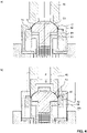
- FIG. 3 shows the tool of the first stage S1, where in a) the tool is shown at the beginning of the stroke and in b) the tool is shown at the end of the stroke.
- the component height is set at this stage and the transition area 37 between the flange 15 and the cylindrical or slightly conically converging area 53 is already brought into the final shape.
- the in Fig. 3 a) inserted blank R between a drawing die 39, which rests on the outer surface 7 of the rounded portion 17, and a blank holder 41, which rests on the inside 6, out.
- a drawing die 40 which is mounted on the inside of the blank holder 41, now moves into the bottom area 8 and thus forms the neck area 14 (cf Fig. 3 b) ).
- the guide sleeve 43 and the counter-holder 42 move from bottom to bottom Contact surface 55 of the drawing die, the sharp edge 37 being formed at the transition between the contact surface 55 and the rounded area 45 of the drawing die at the transition between the flange 15 and the dome area 5 .
- the process is also managed in such a way that the required component height H is set.
- the material in the critical dome area 5 is guided and supported at all times by the inner contact surface 44 of the blank holder 41 and the contact surface 45 of the drawing die 39, so that damage or overloading with resulting porosity of the lacquer layer can be avoided.
- the height is first set in combination with the first drag.
- the part rests on the flange 15 because the indentation sleeve is wider.
- the blank R is positioned via a hold-down device on the press-in sleeve 43 via the blank holder 41, which is positively fitted to the blank R.
- the material is drawn into the die 39 and the first train begins to form.
- the flange 15 is then placed down to the desired part height.
- the radius Ra is also formed here, which is typically in the range of at least 0.30 mm.
- the flange 15 is set and the volume of material required for drawing the flange is already in the right place.
- the upper area is then pulled further.
- Figure 12 shows the tool for forming the fold in S9, with a) showing the tool at the start of the stroke and b) showing the tool at the end of the stroke.
- the output component that is in Fig. 2 h) is shown, is held comprehensively and flatly here between a drawing punch 46 and a receptacle 51 in the dome area 5 .
- the flange 15 is guided between an upper blank holder 48 and drawing die 49 below.
- At the lower end of the drawing die there is a shaped piece 47 which serves as a shaping element for the drawing process 3 .
- a lifting sleeve or impression sleeve 50 is arranged between the bottom drawing die 49 and the receptacle 51 .
- the drawing punch 46 and the receptacle 51 move downwards in parallel and thereby clamp the material in the dome area 5.
- the blank holder 48 clamps the flange 15 on the drawing die 49 (this is rigid) and thus draws the offset (no inversion process , but deep-drawing), with the flange 15 withdrawing somewhat from the gap between the two counter-holders 48/49.
- the flange is prepared for drawing, it is only drawn into the die 49.
- the part is controlled by the drawing die 46 via the press-in sleeve 50 onto a spring-loaded, form-fitting receptacle 51 .
- a fold holder 48 prevents the Wrinkling during forming.
- the material on the flange 15 is drawn into the die. This forms the flange height as well as the flange diameter. In addition, the diameter for the lid holder in the body (can body) is drawn out through the die.
Abstract
Verfahren zur Herstellung eines Aerosoldoms (1) mit einem Dombereich (5) mit einem oberseitig angrenzenden, an einer oberen Durchgangsöffnung (32) angeordneten Rollrand (2) und mit einem unterseitig angrenzenden Flanschbereich mit Umstülpung (3), wobei aus einem lackbeschichteten Rohling (R) in einer oder mehreren Stufen eine Zwischenstufe (52) bereitgestellt wird, die die obere Durchgangsöffnung (32) aufweist, nach unten gefolgt von einem Halsabschnitt (14), weiter gefolgt vom Dombereich (5), auf den ein umlaufender gerader Flansch (15) folgt, und wobei diese Zwischenstufe in einer Bearbeitungsstufe (S9) bearbeitet wird, bei der ausschließlich die Umstülpung (3) ausgebildet wird

Description
Die vorliegende Erfindung betrifft ein Verfahren zur Herstellung eines Aerosoldoms sowie einen unter Verwendung eines derartigen verfahrenshergestelltes Aerosoldom.The present invention relates to a method for producing an aerosol dome and an aerosol dome produced using such a method.
Topfförmige Gegenstände aus Metall können in einem kalten Umformprozess aus einem flachen Blechabschnitt umgeformt werden. Typischerweise geschieht dies nach einem Stanzprozess oder kombiniert mit einem solchen in einem einzigen Umformschritt (Tiefziehen), in welchem dem fertigen Bauteil die endgültige Form gegeben wird. Solche Prozesse werden beispielsweise für die Herstellung von Töpfen, Spraydosen, Bauteilen in der Automobilindustrie oder in der Möbelindustrie, für Nahrungsmittelverpackungen etc. eingesetzt. Als Materialien werden dabei insbesondere Aluminium und Weissblech eingesetzt.Pot-shaped metal objects can be formed from a flat section of sheet metal in a cold forming process. This typically happens after a stamping process or combined with one in a single forming step (deep drawing), in which the finished component is given its final shape. Such processes are used, for example, for the production of pots, spray cans, components in the automotive industry or in the furniture industry, for food packaging, etc. Aluminum and tinplate in particular are used as materials.
Insbesondere wenn geringe Materialdicken eingesetzt werden, muss der Umformprozess sorgfältig geführt werden, um Rissbildungen, Faltenbildungen etc. und damit Ausschuss respektive ungenügende Qualität zu vermeiden. Dies gilt vor allem für die Ausbildung von konischen Wandbereichen, weil bei solchen im Gegensatz zur Ausbildung von axial zylindrischen Wandbereichen die Führung im Werkzeug nicht im gleichen Masse gewährleistet ist.Especially when low material thicknesses are used, the forming process must be carried out carefully in order to avoid the formation of cracks, creases, etc. and thus rejects or insufficient quality. This applies above all to the formation of conical wall areas because, in contrast to the formation of axially cylindrical wall areas, guidance in the tool is not guaranteed to the same extent in such cases.
Es ist unter anderem Aufgabe der vorliegenden Erfindung, ein Verfahren zur Herstellung eines Aerosoldoms bereitzustellen, das es ermöglicht, mit möglichst wenig Material (geringe Materialstärke) einen möglichst stabilen Dom ohne Beschädigung einer auf dem Material befindlichen Lackschicht oder Polymerschicht herzustellen.Among other things, the object of the present invention is to provide a method for producing an aerosol dome that makes it possible to produce a dome that is as stable as possible with as little material as possible (low material thickness) without damaging a lacquer layer or polymer layer on the material.
Gegenstand der vorliegenden Erfindung ist entsprechend ein Verfahren nach Anspruch 1 respektive eine Verwendung gemäß Anspruch 14 und ein Aerosoldom nach Anspruch 15. Konkret betrifft die vorliegende Erfindung ein Verfahren zur Herstellung eines Aerosoldoms mit einem Dombereich mit einem oberseitig angrenzenden, an einer oberen Durchgangsöffnung angeordneten Rollrand und mit einem unterseitig angrenzenden Flanschbereich mit Umstülpung. Dabei wird aus einem lackbeschichteten oder polymerbeschichteten Rohling in einer oder mehreren Stufen eine Zwischenstufe bereitgestellt, die die obere Durchgangsöffnung aufweist, nach unten gefolgt von einem vorzugsweise im wesentlichen zylindrischen Halsabschnitt, weiter gefolgt vom Dombereich, auf den ein umlaufender gerader Flansch folgt. Diese Zwischenstufe wird in einer Bearbeitungsstufe bearbeitet, bei der ausschließlich die Umstülpung in einem Tiefziehprozess ausgebildet wird.The subject matter of the present invention is accordingly a method according to
Ein solches Verfahren ist bevorzugt weiterhin dadurch gekennzeichnet, dass die Zwischenstufe einen nach außen gerichteten Kragen und/oder beim Übergang von Dombereich zu Halsbereich eine nach außen gewölbten Welle aufweist.Such a method is preferably further characterized in that the intermediate stage has an outwardly directed collar and/or an outwardly curved corrugation at the transition from the dome area to the neck area.
Auf die Bearbeitungsstufe zur Erzeugung der Umstülpung folgt vorzugsweise wenigstens eine weitere Stufe direkt oder indirekt, in der aus dem Halsabschnitt ein Rollrand ausgebildet wird.The processing stage for producing the inversion is preferably followed directly or indirectly by at least one further stage in which a rolled edge is formed from the neck section.
Gemäß einer weiteren bevorzugten Ausführungsform folgt auf die Bearbeitungsstufe zur Erzeugung der Umstülpung wenigstens eine weitere Stufe direkt oder indirekt, in der aus dem verbleibenden Flansch eine Vorstufe oder der endgültige Randcurl erzeugt wird, wobei vorzugsweise diese weitere Stufe, wenn nur eine Vorstufe ausgebildet wird, kombiniert mit einer Stufe durchgeführt wird, bei welcher aus dem Halsabschnitt ein Rollrand ausgebildet wird, und wobei dann vorzugsweise diese Stufe gefolgt wird von einer weiteren Stufe, in welcher der Randcurl ausgebildet wird. Bevorzugt folgen dann keine weitere Schritte mehr. Der lackbeschichtete Rohling wird vorzugsweise in Topfform mit einem umlaufenden Flansch, einem abgerundeten Bereich und einem Boden aber ohne Halsbereich vorgelegt, und in wenigstens einer ersten Stufe dieser Rohling auf die benötigte Teilehöhe H (typischerweise im Bereich von 10-40 mm) vor Erzeugung eines Rollrandes mit einem axialen Halsbereich umgeformt, und vorzugsweise weiterhin in dieser ersten Stufe der Radius am Übergangsbereich zwischen dem Flansch und dem abgerundeten Bereich reduziert, vorzugsweise auf einen Radius im Bereich von 0.2- 1.0 mm, insbesondere vorzugsweise im Bereich von 0.3 - 0.6 mm.According to a further preferred embodiment, the processing stage for producing the eversion is followed directly or indirectly by at least one further stage in which a preliminary stage or the final edge curl is produced from the remaining flange, this further stage preferably being combined if only one preliminary stage is formed with a stage in which the neck portion is formed into an edge curl, and then preferably this stage is followed by a further stage in which the edge curl is formed. No further steps then preferably follow. The paint-coated blank is preferably presented in the form of a pot with a circumferential flange, a rounded area and a bottom but without a neck area, and in at least a first stage this blank is cut to the required part height H (typically in the range of 10-40 mm) before a rolled edge is produced formed with an axial neck area, and preferably further in this first step the radius at the transition area between the flange and the rounded area is reduced, preferably to a radius in the range of 0.2-1.0 mm, particularly preferably in the range of 0.3-0.6 mm.
Nach der ersten Stufe kann in wenigstens einer, vorzugsweise in zwei weiteren Stufen, einer zweiten Stufe und einer dritten Stufe, der Halsbereich weiter ausgeformt werden, insbesondere der Radius des Bereichs zwischen dem axialen Halsbereich und dem radialen Boden reduziert werden, vorzugsweise auf eine scharfe Kante mit einem Radius Radius im Bereich von 0.05- 0.6 mm, insbesondere vorzugsweise im Bereich von 0.1 - 0.2 mm.After the first stage, the neck area can be shaped further in at least one, preferably in two further stages, a second stage and a third stage, in particular the radius of the area between the axial neck area and the radial base can be reduced, preferably to a sharp edge with a radius in the range of 0.05-0.6 mm, particularly preferably in the range of 0.1-0.2 mm.
Gemäß einer weiteren bevorzugten Ausführungsform wird in wenigstens einer fünften Stufe der Boden, der ggf. mit einem Ritzen vorbereitet wurde, als Napf unter Ausbildung der oberen Durchgangsöffnung aus dem Werkzeug geführt, oder unter Ausbildung der oberen Durchgangsöffnung ausgestanzt, und vorzugsweise anschließend in einer sechsten Stufe die dadurch gebildete umlaufende Kante zu einem Kragen umgelegt, wobei weiterhin vorzugsweise die fünfte Stufe und die sechste Stufe nach den zwei weiteren Stufen wie oben dargelegt durchgeführt werden.According to a further preferred embodiment, in at least a fifth stage, the bottom, which may have been prepared with a scratch, is guided out of the tool as a bowl, forming the upper through-opening, or punched out to form the upper through-opening, and preferably subsequently in a sixth stage the peripheral edge thus formed is folded over to form a collar, with the fifth step and the sixth step also preferably being carried out after the two further steps as set out above.
Weiterhin wird bevorzugt, wenn in einer Stufe, vorzugsweise in der fünften Stufe gemäß Beschreibung oben, im Dombereich beim Übergang von Dombereich zu Halsbereich eine nach außen gewölbte Welle ausgebildet.Furthermore, it is preferred if in one stage, preferably in the fifth stage according to Description above, in the dome area, at the transition from the dome area to the neck area, an outwardly curved wave is formed.
In einer Stufe, vorzugsweise in der zweiten Stufe und/oder der dritten Stufe und/oder der vierten Stufe, kann zusätzlich im Übergangsbereich zwischen Boden und Halsbereich geritzt werden, um die Entnahme des Bodens vorzubereiten.In one stage, preferably in the second stage and/or the third stage and/or the fourth stage, the transition area between the base and the neck area can also be scored in order to prepare for the removal of the base.
Eine weitere bevorzugte Ausführungsform ist dadurch gekennzeichnet, dass zum Herstellen des Rollrandes aus einem zylindrischen Randabschnitt des Halsbereichs in einem ersten Schritt, vorzugsweise in der fünften Stufe wie oben dargelegt, eine Anfangszone des Randabschnittes durch ein zwangsläufig gesteuertes Werkzeug zum Kragen umgelegt wird und in einem zweiten Schritt, vorzugsweise in der weiteren Stufe wie oben dargelegt, nachfolgend ein Bördelstempel in den umgelegten Randabschnitt einfährt und diesen zu einer Rolle bördelt, wobei im ersten Schritt die Anfangszone des Randabschnittes durch das einen Umlegestempel und Gegenhalter umfassende Werkzeug um einen Winkel im Bereich von 75-105°, vorzugsweise im Bereich von 80-100°, oder im Bereich von 85-95°, von der axialen Richtung zu einem im Wesentlichen radialen umlaufenden Flansch umgelegt werden kann.A further preferred embodiment is characterized in that to produce the rolled edge from a cylindrical edge section of the neck area, in a first step, preferably in the fifth stage as set out above, an initial zone of the edge section is folded over to form the collar using a positively controlled tool and in a second step step, preferably in the further stage as set out above, a flanging die then moves into the folded edge section and flangs it into a roll, with the first step turning the initial zone of the edge section by an angle in the range of 75- 105°, preferably in the range of 80-100°, or in the range of 85-95°, from the axial direction to a substantially radial circumferential flange.
Der Biegeradius zwischen dem umlaufenden Flansch und dem daran angrenzenden axialen Abschnitt ist bevorzugt kleiner als die doppelte Materialstärke des zylindrischen Randabschnitts, vorzugsweise liegt der Biegeradius im Bereich von 0.5-1.5 mal, insbesondere vorzugsweise im Bereich von 0.75-1.25 mal der Materialstärke des zylindrischen Randabschnitts.The bending radius between the circumferential flange and the adjoining axial section is preferably smaller than twice the material thickness of the cylindrical edge section, preferably the bending radius is in the range of 0.5-1.5 times, particularly preferably in the range of 0.75-1.25 times the material thickness of the cylindrical edge section.
Die radiale Länge des Flansches beträgt weiterhin vorzugsweise im Bereich von 2-5 mal, vorzugsweise im Bereich von 3-4 mal die Materialstärke des zylindrischen Randabschnitts. Das Material das Rohlings ist vorzugsweise auf beiden Seiten oder wenigstens auf der zukünftigen Oberseite (Außenfläche 7) mit einer dichten Lackschicht versehen. Der Lack kann direkt auf dem Metall angeordnet sein, oder über eine zusätzliche Haftvermittlerschicht. Es handelt sich dabei bevorzugt um einen Polyesterlack, ein Acrylatbasiertes System oder ein Metacrylat-basiertes System oder einen Polyurethanlack. Ein solcher Lack kann wasserbasiert sein oder lösungsmittelbasiert, und er kann vernetzt sein. Vorzugsweise ist der Lack ohne VOC aufgebracht.The radial length of the flange is also preferably in the range of 2-5 times, preferably in the range of 3-4 times the material thickness of the cylindrical edge section. The material of the blank is preferably provided with a dense layer of lacquer on both sides or at least on the future upper side (outer surface 7). The paint can be applied directly to the metal or via an additional adhesion promoter layer. It is preferably a polyester paint, an acrylate-based system or a methacrylate-based system or a polyurethane paint. Such a paint can be water-based or solvent-based, and it can be cross-linked. The paint is preferably applied without VOC.
Der Rohling kann auch mit einer dichten Polymerschicht respektive Kunststoffschicht versehen sein, oder auch mit mehreren derartigen Schichten. Dann gibt es üblicherweise zusätzliche Haftvermittlerschichten inzwischen dem Metall und der wenigstens einen Kunststoffschicht. Die Kunststoffschicht kann aus Polyethylenterephthalat (PET) oder Polypropylen (PP) oder Polyethylen (PE) bestehen, oder einer Mischung aus solchen Systemen. Die Kunststoffschicht kann zusätzlich die üblichen Additive (insbesondere Weichmacher, Füllstoffe) und vor allem gegebenenfalls Farbstoffe oder Pigmente in den üblichen Proportionen aufweisen.The blank can also be provided with a dense polymer layer or plastic layer, or with several such layers. Then there are usually additional adhesion promoter layers in between the metal and the at least one plastic layer. The plastic layer can consist of polyethylene terephthalate (PET) or polypropylene (PP) or polyethylene (PE), or a mixture of such systems. The plastic layer can also contain the usual additives (especially Plasticizers, fillers) and, above all, optionally dyes or pigments in the usual proportions.
Die Dicke einer solchen Lackschicht oder Kunststoffschicht liegt typischerweise im Bereich von 5-40 µm (inklusive gegebenenfalls vorhandener Haftvermittlerschicht).The thickness of such a paint layer or plastic layer is typically in the range of 5-40 μm (including any adhesion promoter layer that may be present).
Die Materialstärke des Rohlings liegt typischerweise im Bereich von 0.1 - 1 mm, vorzugsweise im Bereich von 0.15-0.4 mm, insbesondere vorzugsweise im Bereich von 0.18-0.34 mm.The material thickness of the blank is typically in the range of 0.1-1 mm, preferably in the range of 0.15-0.4 mm, particularly preferably in the range of 0.18-0.34 mm.
Beim Material des Rohlings handelt es sich vorzugsweise um Stahlblech, vorzugsweise um Weissblech. Es ist aber auch Aluminium möglich.The material of the blank is preferably sheet steel, preferably tinplate. However, aluminum is also possible.
Bevorzugt handelt es sich beim Material des Rohlings (R) um Stahlblech
insbesondere bevorzugt mit einer Streckgrenze, bestimmt gemäss DIN EN 10002-1:2001, von wenigstens 500 MPa, vorzugsweise wenigstens 520 MPa, insbesondere vorzugsweise wenigstens 550 MPa,
und/oder mit einer Zugfestigkeit, bestimmt gemäss DIN EN 10002-1:2001, von wenigstens 500 MPa, vorzugsweise von wenigstens 550 MPa, insbesondere vorzugsweise wenigstens 575 MPa.The material of the blank (R) is preferably sheet steel
particularly preferably with a yield point, determined according to DIN EN 10002-1:2001, of at least 500 MPa, preferably at least 520 MPa, particularly preferably at least 550 MPa,
and/or with a tensile strength, determined according to DIN EN 10002-1:2001, of at least 500 MPa, preferably at least 550 MPa, particularly preferably at least 575 MPa.
Oder es handelt sich es sich beim Material des Rohlings (R) um Stahlblech, vorzugsweise um Weissblech des Typs TH520, Werkstoffnummer 1.0384; TH550. Werkstoffnummer 1.0373; TH580, Werkstoffnummer 1.0382; TH620, Werkstoffnummer 1.0374, oder die entsprechenden TS-Typen, jeweils gemäss DIN EN 10202: 2001, und/oder DR8, DR8, DR8.5, oder DR9, jeweils gemäss AISI/ASTM 623.Or the material of the blank (R) is sheet steel, preferably TH520 type tinplate, material number 1.0384; TH550. material number 1.0373; TH580, material number 1.0382; TH620, material number 1.0374, or the corresponding TS types, each according to DIN EN 10202: 2001, and/or DR8, DR8, DR8.5, or DR9, each according to AISI/ASTM 623.
Weiter betrifft die vorliegende Erfindung die Verwendung eines solchen Verfahrens zur Herstellung eines Aerosoldomes für eine Spraydose.The present invention further relates to the use of such a method for producing an aerosol dome for a spray can.
Weiter betrifft die vorliegende Erfindung ein Werkzeug zur Durchführung eines solchen Verfahrens.The present invention also relates to a tool for carrying out such a method.
Zu guter letzt betrifft die vorliegende Erfindung einen Aerosoldom für eine Spraydose hergestellt nach einem Verfahren wie oben dargelegt respektive in einem Werkzeug wie oben angegeben.Last but not least, the present invention relates to an aerosol dome for a spray can produced by a method as set out above or in a tool as set out above.
Weitere Ausführungsformen sind in den abhängigen Ansprüchen angegeben.Further embodiments are specified in the dependent claims.
Bevorzugte Ausführungsformen der Erfindung werden im Folgenden anhand der Zeichnungen beschrieben, die lediglich zur Erläuterung dienen und nicht einschränkend auszulegen sind. In den Zeichnungen zeigen:
- Fig. 1
- eine Stufenfolge zur Herstellung eines Aerosoldoms aus einem topfförmigen Rohling;
- Fig. 2
- eine erfindungsgemäße Stufenfolge zur Herstellung eines Aerosoldoms aus einem topfförmigen Rohling;
- Fig. 3
- das Werkzeug der ersten Stufe, wobei in a) das Werkzeug am Anfang des Hubs und in b) das Werkzeug am Ende des Hubs dargestellt ist; und
- Fig. 4
- das Werkzeug zur Ausbildung der Umstülpung, wobei in a) das Werkzeug am Anfang des Hubs und in b) das Werkzeug am Ende des Hubs dargestellt ist.
- 1
- a sequence of steps for producing an aerosol dome from a pot-shaped blank;
- 2
- a sequence of steps according to the invention for the production of an aerosol dome from a pot-shaped blank;
- 3
- the first stage tool, with a) showing the tool at the beginning of the stroke and b) showing the tool at the end of the stroke; and
- 4
- the tool for forming the inversion, in a) the tool at the beginning of the stroke and in b) the tool at the end of the stroke being shown.
Um aus einem topfförmigen Rohling R aus einem dünnen, mit einem lackbeschichteten Material einen Aerosoldom herzustellen, werden nach den bekannten Verfahren mehrere Stufen durchlaufen.In order to produce an aerosol dome from a pot-shaped blank R made of a thin material coated with a paint, several stages are run through according to the known methods.
Ein mögliches Verfahren wird im Zusammenhang mit
Ein in einem vorgängigen Stanz- und Umformprozess hergestellter topfförmiger Rohling R wird dem Prozess wie mit dem Pfeil 21 dargestellt zugeführt. Es ist aber auch möglich, dass die Herstellung dieses topfförmigen Rohlings R, der typischerweise aus einem bandförmig zugeführten Rohmaterial zunächst ausgestanzt und dann zu einem Becher tiefgezogen wird, was in einem oder zwei Schritten geschehen kann, im Rahmen der hier beschriebenen Stufenfolge als ersten Schritt durchzuführen.A pot-shaped blank R produced in a previous stamping and forming process is supplied to the process as shown by
Dieser Rohling R, dargestellt in a) verfügt über einen umlaufenden Flansch 15, der über einen zunächst zylindrischen Bereich 53 in einen abgerundeten Bereich 17 übergeht, und der einen geschlossenen Boden 18 aufweist.This blank R, shown in a), has a
In der durch den Pfeil 22 dargestellten Bearbeitung in der ersten Station S1 wird dieser Rohling R einem ersten Ziehen Z1 unterzogen, wobei mit einem Stempel in den Innenraum des Rohlings eingefahren wird und der Rohling gegen eine Matrize gepresst wird. Daraus resultiert das in b) dargestellte Bauteil. Es werden in diesem Schritt der zylindrische Bereich 53 und Teile des abgerundeten Bereichs 17 in einen Dombereich 5 umgeformt, sowie aus Teilen des abgerundeten Bereichs 17 und des Bodens 18 ein Halsabschnitt 14, der über einen Übergang 20 auf den Dombereich folgt. Der Boden 18 erhält einen geringeren Durchmesser, und eine Rundung 19 wird beim Übergang vom Boden 18 zum Halsabschnitt eingestellt. Der Flansch 15 bleibt im Wesentlichen bestehen und das Bauteil hat noch nicht seine endgültige Höhe, diese wird erst in Folgeschritten eingestellt.In the processing shown by the
In einem durch den Pfeil 23 dargestellten Schritt RP wird anschließend der Rand beschnitten, d. h. die radiale Länge des Flansches 15 auf den gewünschten Wert eingestellt, dieser Schritt findet hier im Rahmen der Stationen S2 und S3 statt (eine davon ist eine Leerstation), dies führt zum Bauteil gemäß c).In a step RP represented by the arrow 23, the edge is then cropped, i. H. the radial length of the
In der durch den Pfeil 24 dargestellten Bearbeitung in der vierten Station S4 wird dieses Bauteil einem zweiten Ziehen Z2 unterzogen, wobei wiederum mit einem Stempel in den Innenraum eingefahren wird und das Bauteil gegen eine Matrize gepresst wird. Daraus resultiert das in d) dargestellte Bauteil. Es werden in diesem Schritt der Dombereich 5 umgeformt und erhöht, sowie der Halsabschnitt 14 verlängert und im Radius reduziert.In the processing shown by the
In der durch den Pfeil 25 dargestellten Bearbeitung in der fünften Station S5 wird dieses Bauteil einem dritten Ziehen Z3 unterzogen, wobei erneut mit einem Stempel in den Innenraum eingefahren wird und das Bauteil gegen eine Matrize gepresst wird. Daraus resultiert das in e) dargestellte Bauteil. In diesem Schritt wird im Wesentlichen nur der vormals Runde Bereich 19 in eine scharfe Kante 31 beim Übergang vom Halsbereich 14 zum Boden 18 geformt.In the processing shown by the
In der durch den Pfeil 26 dargestellten Bearbeitung in der sechsten Station S6 wird dieses Bauteil einem Ritzen Ri unterzogen, d. h. im Bereich des Übergangs 31 zwischen Boden 18 und Halsbereich 14 wird eine umlaufende Ritzung erzeugt, deren Funktion in der weiteren Bearbeitung folgende ist: Der Boden wird vorbereitet, um in der nächsten Station weggerissen und als Napf gezogen aus dem Werkzeug geführt zu werden. Daraus resultiert das in f) dargestellte Bauteil.In the processing shown by the
In der durch den Pfeil 27 dargestellten entscheidenden Bearbeitung in der siebten Station S7 wird dieses Bauteil gleichzeitig mehreren Schritten U unterzogen. Einerseits wird aus Teilen des Dombereichs 5 eine Umstülpung 3 erzeugt. Diese Umstülpung geht über einen vertikalen Abschnitt 9 in den Flansch 15 über und radial nach innen über einen Angrenzungsbereich 8 in den Dombereich 5. Durch die bei dieser Art der Umformung entstehende Materialaufdickung (stauchen) ergibt sich eine grosse Belastung auf die Beschichtung, die zu Abplatzungen der Schicht führen kann. Auf der anderen Seite können mit einem geringeren Winkel anschließend in einer Dose eingebaut höhere Drücke ausgehalten werden. Gleichzeitig wird in diesem Schritt im Dombereich 5 eine leichte nach außen gerichtete Welle 13 ausgebildet, die an den Halsabschnitt 14 angrenzt. Ebenfalls gleichzeitig wird in dieser Stufe der Boden, der in Station 5 vorbereitet wurde, als Napf aus dem Werkzeug geführt, sodass oben eine Durchgangsöffnung 32 resultiert sowie eine freie gerade Kante 16 des zylindrischen Abschnitts 14, und es wird die Bauteilhöhe eingestellt. Daraus resultiert das in g) dargestellte Bauteil.In the decisive processing in the seventh station S7, represented by the
In der durch den Pfeil 28 dargestellten Bearbeitung A in der achten Station S8 wird dieses Bauteil einem Ankippen A unterzogen. D.h. eine Anfangszone des Randabschnittes 16 wird durch ein i.d.R. zwangsläufig gesteuertes Werkzeug umgelegt und erst danach im Rahmen der nächsten Stufe S9 in einem zweiten Schritt ein Bördelstempel in den umgelegten Randabschnitt eingefahren und dieser zu einer Rolle 2 gebördelt. In diesem Schritt S8 wird die Anfangszone des Randabschnittes 16 durch ein einen Umlegestempel und Gegenhalter umfassendes Werkzeug um einen Winkel im Bereich von 75-105 Grad von der axialen Richtung zu einem im Wesentlichen radialen umlaufenden Flansch 12 umgelegt. Daraus resultiert das in h) dargestellte Bauteil.In the processing A shown by the
In der durch den Pfeil 29 dargestellten Bearbeitung W in der neunten Station S9 wird bei diesem Bauteil einerseits der Rollrand 2 ausgebildet, und andererseits die radiale Umlaufkante des Flansches 15 in einer Vorstufe 11 umgelegt, sodass ein horizontaler Flanschabschnitt 10 verbleibt. Daraus resultiert das in i) dargestellte Bauteil.In the processing W shown by the
Zu guter letzt wird in der durch den Pfeil 30 dargestellten Bearbeitung RC in der elften Station S11 der endgültige Randcurl 4 erzeugt.Last but not least, in the processing RC represented by the
Bei dieser Stufenfolge zur Herstellung des Aerosol-Deckels wird der Flansch 15 umgestülpt. Neu soll dieser jedoch mit einem materialschonenderen Verfahren tiefgezogen werden. Bei diesem Herstellverfahren der Aerosol-Deckel wird der äussere Bereich des Dombereichs zur Umstülpung 3 umgestülpt und somit der Flansch für die Folgestation S9 vorbereitet. Bei dieser Umformart kommt es jedoch zu unregelmässigen Lackverletzungen am Deckel.In this sequence of steps for manufacturing the aerosol cap, the
Besonderes Augenmerk gilt dem Umformschritt der Stufe S7 nach dem Ritzen Ri beim Umstülpen U, bei dem das Teil neben dem Ausformen der Welle 13 und dem Deckel abheben eine Materialverschiebung stattfindet. Hierbei wird die Höhe des Teils und der fürs Wulsten benötigte Flanschdurchmesser eingestellt. Da hier das Material in einem bestimmten Bereich der Umformung frei gestellt sein muss und nicht korrekt gehalten ist, kommt es zu unterschiedlichen Zug-, Druck- und Biegespannungen am Blech, woraus die Lackbeschädigung resultieren kann.Particular attention is paid to the forming step of stage S7 after scoring Ri during inversion U, in which the part is lifted apart from the forming of the
Durch einen neuen Umformschritt und eine andere Stufenfolge werden die Lackverletzungen vermieden. Dabei wird eine materialschonendere Umformung in Form eines Ziehens vollzogen. Es wird zunächst die Höhe des Teils eingestellt (siehe Ziehen Z1 und Höhe einstellen in S1 in
Ein Verfahren nach der Erfindung ist in
Ein in einem vorgängigen Stanz- und Umformprozess hergestellter topfförmiger Rohling R wird dem Prozess wie mit dem Pfeil 21 dargestellt zugeführt. Es ist auch möglich, dass die Herstellung dieses topfförmigen Rohlings R, der typischerweise aus einem bandförmig zugeführten Rohmaterial zunächst ausgestanzt und dann zu einem Becher tiefgezogen wird, was in einem oder zwei Schritten geschehen kann, im Rahmen der hier beschriebenen Stufenfolge als ersten Schritt durchzuführen.A pot-shaped blank R produced in a previous stamping and forming process is supplied to the process as shown by
Dieser Rohling R, dargestellt in a) verfügt über einen umlaufenden Flansch 15, der über einen Übergang 38 über einen zunächst nahezu zylindrischen Bereich 53 in einen abgerundeten Bereich 17 übergeht, und der einen geschlossenen Boden 18 aufweist.This blank R, shown in a), has a
Beim Material des Rohlings R handelt es sich um Stahlblech, namentlich um Weissblech, mit einer Streckgrenze (bestimmt nach EN 10202:2001 insbesondere Kapitel 8.2 und den Messverfahren gemaess DIN EN 10002-1:2001) von wenigstens 550 MPa. Es hat eine Zugfestigkeit (bestimmt nach EN 10202:2001 insbesondere Kapitel 8.2 und den Messverfahren gemaess DIN EN 10002-1:2001) von wenigstens 575 MPa. Typischerweise handelt es sich beim Material um Weissblech des Typs TH520 (Werkstoffnummer 1.0384), TH550 (Werkstoffnummer 1.0373), TH580 (Werkstoffnummer 1.0382), TH620 (Werkstoffnummer 1.0374), oder die entsprechenden TS-Typen, jeweils gemäss DIN EN 10202: 2001 Alternativ formuliert vom Typ DR8, DR8, DR8.5, oder DR9, jeweils gemäss AISI/ASTM 623. Die entsprechenden Zusammensetzungen und Eigenschaften dieser Materialien werden in den angegebenen Normen definiert.The material of the blank R is sheet steel, namely tinplate, with a yield point (determined according to EN 10202:2001, in particular Chapter 8.2 and the measurement method according to DIN EN 10002-1:2001) of at least 550 MPa. It has a tensile strength (determined according to EN 10202:2001, in particular Chapter 8.2 and the measuring method according to DIN EN 10002-1:2001) of at least 575 MPa. Typically, the material is TH520 (material number 1.0384), TH550 (material number 1.0373), TH580 (material number 1.0382), TH620 (material number 1.0374) tinplate, or the corresponding TS types, each formulated according to DIN EN 10202: 2001 alternatively of type DR8, DR8, DR8.5, or DR9, each according to AISI/ASTM 623. The corresponding compositions and properties of these materials are defined in the standards indicated.
Das Material ist auf beiden Seiten oder wenigstens auf der zukünftigen Oberseite (Außenfläche 7) mit einer Lackschicht versehen, hier eingesetzt wurde ein Polyesterlack. Der Rohling kann auch mit einer Polymerschicht respektive Kunststoffschicht versehen sein, oder auch mit mehreren derartigen Schichten. Möglich ist beispielsweise das kommerzielle System Protact®.The material is provided with a layer of lacquer on both sides or at least on the future upper side (outer surface 7), a polyester lacquer was used here. The blank can also be provided with a polymer layer or plastic layer, or with several such layers. For example, the commercial system Protact ® is possible.
In der durch den Pfeil 22 dargestellten Bearbeitung in der ersten Station S1 wird dieser Rohling R einem ersten Ziehen Z1 unterzogen, wobei mit einem Stempel in den Innenraum des Rohlings eingefahren wird und der Rohling gegen eine Matrize gepresst wird (vgl. auch
In einem durch den Pfeil 33 dargestellten Bearbeitung in der zweiten Station S2 wird dieses Bauteil einem zweiten Ziehen Z2 unterzogen, wobei wiederum mit einem Stempel in den Innenraum eingefahren wird und das Bauteil gegen eine Matrize gepresst wird. Daraus resultiert das in c) dargestellte Bauteil. Es werden in diesem Schritt der Dombereich 5 weiter umgeformt, sowie der Halsabschnitt 14 im Radius reduziert.In a machining operation in the second station S2, shown by the
In der durch den Pfeil 34 dargestellten Bearbeitung wird in der dritten Station S3 wird dieses Bauteil einem dritten Ziehen Z3 unterzogen, wobei erneut mit einem Stempel in den Innenraum eingefahren wird und das Bauteil gegen eine Matrize gepresst wird. Daraus resultiert das in d) dargestellte Bauteil. In diesem Schritt wird im Wesentlichen nur der vormals Runde Bereich 19 in eine scharfe Kante 31 beim Übergang vom Halsbereich 14 zum Boden 18 geformt.In the processing shown by the
In der durch den Pfeil 26 dargestellten Bearbeitung in der vierten Station S4 wird dieses Bauteil einem Ritzen Ri unterzogen, d. h. im Bereich Übergangs 31 zwischen Boden 18 und Hals 14 wird eine umlaufende Ritzung erzeugt, deren Funktion in der weiteren Bearbeitung folgende ist: Der Boden wird vorbereitet, um bei der nächsten Station weggerissen und als Napf gezogen aus dem Werkzeug geführt zu werden. Daraus resultiert das in e) dargestellte Bauteil.In the processing shown by the
In der durch den Pfeil 25 dargestellten folgenden Bearbeitung BA in der fünften Station S5 wird der Boden 18, der in Station 4 vorbereitet wurde, als Napf aus dem Werkzeug geführt, ausgestanzt und gleichzeitig die Welle 13 im Dombereich 5 ausgebildet, namentlich in jenem Bereich, der an den Halsbereich 14 angrenzt. Daraus resultiert das in f) dargestellte Bauteil.In the following processing BA in the fifth station S5, represented by the
In der durch den Pfeil 28 dargestellten Bearbeitung KA in der sechsten Station S6 wird dieses Bauteil einem Ankippen A unterzogen. D.h. eine Anfangszone des Randabschnittes 16 wird durch ein i.d.R. zwangsläufig gesteuertes Werkzeug umgelegt und erst danach im Rahmen einer weiteren Stufe S10 in einem zweiten Schritt ein Bördelstempel in den umgelegten Randabschnitt eingefahren und dieser zu einer Rolle 2 gebördelt. In diesem Schritt S6 wird die Anfangszone des Randabschnittes 16 durch ein einen Umlegestempel und Gegenhalter umfassendes Werkzeug um einen Winkel im Bereich von 75-105 Grad von der axialen Richtung zu einem im Wesentlichen radialen umlaufenden Flansch 12 umgelegt. Daraus resultiert das in g) dargestellte Bauteil.In the processing KA shown by the
In der durch den Pfeil 35 dargestellten Bearbeitung RB wird anschließend der Rand beschnitten, d. h. die radiale Länge des Flansches 15 auf den gewünschten Wert eingestellt, dieser Schritt findet hier im Rahmen der Stationen S7 und S8 statt (eine davon ist eine Leerstation), dies führt zum Bauteil gemäß h).In the processing RB represented by the
Dieses Bauteil ist nun hinsichtlich Formgebung soweit fertig, dass nur noch die abschließenden Schritte am Flansch 15 und am Halsbereich 14 ausgeführt werden müssen, und in allen Schritten bis zu dieser Stelle kann das Bauteil jeweils optimal geführt werden. Damit wird der Schritt der Umstülpung in der nächsten Stufe ganz allein durchgeführt und mit einem Bauteil, bei dem sämtliche Umformungen und Stanzungen bereits durchgeführt wurden, soweit sie überhaupt vor diesem Schritt durchgeführt werden können, ohne dadurch Probleme in Bezug auf die Prozessführung nach sich zu ziehen. Insbesondere ist in diesem Moment bereits der der Boden 18 ausgestanzt und der Kragen 12 ausgebildet, und ebenfalls liegt bereits die umlaufende Welle 13 vor, und die endgültige Bauteilhöhe, bis auf das Rollen des Rollrandes 2, ist erstellt.This component is now so far finished in terms of shaping that only the final steps on the
In der durch den Pfeil 54 dargestellten entscheidenden Bearbeitung in der neunten Station S9 wird nun dieses Bauteil nur dem Schritt FZ unterzogen. Dabei wird aus Teilen des Dombereichs 5 eine Umstülpung 3 erzeugt, und dabei ist es möglich, das Material optimal zu halten und zu führen. Diese Umstülpung geht über einen vertikalen Abschnitt 9 in den Flansch 15 über und radial nach innen im Angrenzungsbereich 8 in den Dombereich 5. Dies führt zum Bauteil gemäß i).In the decisive processing in the ninth station S9, represented by the
In der durch den Pfeil 29 dargestellten Bearbeitung W in der zehnten Station S10 wird bei diesem Bauteil einerseits der Rollrand 2 ausgebildet, und andererseits die radiale Umlaufkante des Flansches 15 in einer Vorstufe 11 umgelegt, sodass ein horizontaler Flanschabschnitt 10 verbleibt. Daraus resultiert das in k) dargestellte Bauteil.In the processing W shown by the
Zu guter letzt wird in der durch den Pfeil 30 dargestellten Bearbeitung RC in der elften Station S11 der endgültige Randcurl 4 erzeugt.Last but not least, in the processing RC represented by the
Losgelöst von der effektiven Stufenfolge werden hier die für die Umformung der Partie des Flansches die Stufen S1 und S9 eingesetzt. Ein Vergleich mit der Folge nach
Im Detail wird also zunächst in Kombination mit dem ersten Ziehen die Höhe eingestellt. Dadurch kann durchgängig mit grösseren Eindrückhülsen 43 gefahren werden und der Beschädigungspunkt am Radius wird verringert respektive ist gar nicht mehr vorhanden. Das Teil liegt auf dem Flansch 15 auf, da die Eindruckhülse breiter ist. Der Rohling R wird über einen Niederhalter auf der Eindrückhülse 43 über den Faltenhalter 41, welcher formschlüssig zum Rohling R ist, positioniert. Dann wird das Material in die Matrize 39 eingezogen und der erste Zug beginnt sich auszuformen. In der Endlage wird dann der Flansch 15 abgelegt auf die gewünschte Teilehöhe. Hier wird auch gleich der Radius Ra angeformt dieser liegt typischerweise im Bereich von mindestens 0.30 mm.In detail, the height is first set in combination with the first drag. As a result, it is possible to drive consistently with larger press-in
Dadurch ist der Flansch 15 angestellt und das für das Flanschziehen benötigte Materialvolumen bereits am richtigen Ort.As a result, the
In den folgenden Stationen wird dann der obere Bereich weiter gezogen.In the following stations, the upper area is then pulled further.
Ist der Flansch für das Ziehen vorbereitet, wird er also nur noch in die Matrize 49 gezogen. Das Teil wird durch den Ziehstempel 46 über die Eindrückhülse 50 auf eine gefederte, formschlüssige Aufnahme 51 gesteuert. Am Flansch verhindert ein Faltenhalter 48 die Faltenbildung während der Umformung.If the flange is prepared for drawing, it is only drawn into the
Nun wird das Material am Flansch 15 in die Matrize eingezogen. Dadurch bildet sich die Flanschhöhe wie auch der Flanschdurchmesser aus. Ausserdem wird der Durchmesser für die Deckelaufnahme im Body (Dosenkörper) durch die Matrize ausgezogen.Now the material on the
Bei der Umformung ist das Material stets eingeschlossen und muss sich dadurch nicht unerwünschtem oder undefiniertem Materialfluss hingeben. Dadurch ist eine materialschonendere Umformung gegeben, wodurch die Lackbeschädigung die Umstülpen entsteht, ausgemerzt wird.
Claims (15)
wobei aus einem lackbeschichteten oder polymerbeschichteten Rohling (R) in einer oder mehreren Stufen eine Zwischenstufe (52) bereitgestellt wird, die die obere Durchgangsöffnung (32) aufweist, nach unten gefolgt von einem Halsabschnitt (14), weiter gefolgt vom Dombereich (5), auf den ein umlaufender gerader Flansch (15) folgt,
und wobei diese Zwischenstufe in einer Bearbeitungsstufe (S9) bearbeitet wird, bei der ausschließlich die Umstülpung (3) ausgebildet wird.Method for producing an aerosol dome (1) with a dome area (5) with a rolled edge (2) arranged on an upper passage opening (32) adjoining the top side and with a flange area adjoining the underside with an inverted portion (3),
wherein from a lacquer-coated or polymer-coated blank (R) an intermediate step (52) is provided in one or more steps, which has the upper through opening (32), followed downwards by a neck section (14), further followed by the dome area (5), followed by a circumferential straight flange (15),
and wherein this intermediate stage is processed in a processing stage (S9) in which only the fold-over (3) is formed.
und/oder dass auf die Bearbeitungsstufe (S9) zur Erzeugung der Umstülpung (3) wenigstens eine weitere Stufe (S10) direkt oder indirekt folgt, in der aus dem verbleibenden Flansch (15) eine Vorstufe (11) oder der endgültige Randcurl (4) erzeugt wird, wobei vorzugsweise diese weitere Stufe, wenn nur eine Vorstufe (11) ausgebildet wird, kombiniert mit einer Stufe durchgeführt wird, bei welcher aus dem Halsabschnitt (14) ein Rollrand (2) ausgebildet wird, und wobei dann vorzugsweise diese Stufe gefolgt wird von einer weiteren Stufe (S11), in welcher der Randcurl (4) ausgebildet wird.Method according to one of the preceding claims, characterized in that the processing stage (S9) for producing the inversion (3) is followed directly or indirectly by at least one further stage (S10) in which a rolled edge (2) is formed from the neck section (14). becomes,
and/or that the processing stage (S9) for producing the eversion (3) is followed directly or indirectly by at least one further stage (S10) in which a preliminary stage (11) or the final edge curl (4) is made from the remaining flange (15). is produced, preferably this further stage, if only a preliminary stage (11) is formed, being carried out in combination with a stage in which a rolled edge (2) is formed from the neck portion (14), and this stage then preferably being followed from a further stage (S11) in which the edge curl (4) is formed.
und/oder dass die radiale Länge des Flansches (12) im Bereich von 2-5 mal, vorzugsweise im Bereich von 3-4 mal die Materialstärke des zylindrischen Randabschnitts beträgt.Method according to Claim 9, characterized in that the bending radius between the peripheral flange (12) and the axial section adjoining it is smaller than twice the material thickness of the cylindrical edge section, preferably that the bending radius is in the range of 0.5-1.5 times, particularly preferably in the range 0.75-1.25 times the material thickness of the cylindrical edge section,
and/or that the radial length of the flange (12) is in the range of 2-5 times, preferably in the range of 3-4 times the material thickness of the cylindrical edge section.
mit einer Streckgrenze, bestimmt gemäss DIN EN 10002-1:2001, von wenigstens 500 MPa, vorzugsweise wenigstens 520 MPa, insbesondere vorzugsweise wenigstens 550 MPa,
und/oder mit einer Zugfestigkeit, bestimmt gemäss DIN EN 10002-1:2001, von wenigstens 500 MPa, vorzugsweise von wenigstens 550 MPa, insbesondere vorzugsweise wenigstens 575 MPa,
handelt
und/oder dass es sich beim Material des Rohlings (R) um Stahlblech, vorzugsweise um Weissblech des Typs TH520, Werkstoffnummer 1.0384; TH550. Werkstoffnummer 1.0373; TH580, Werkstoffnummer 1.0382; TH620, Werkstoffnummer 1.0374, oder die entsprechenden TS-Typen, jeweils gemäss DIN EN 10202: 2001, und/oder DR8, DR8, DR8.5, oder DR9, jeweils gemäss AISI/ASTM 623, handelt,
und/oder dass es sich bei der Lackierung um eine Lackschicht auf Basis von Polyesterlack, Polyurethanlack, Acrylatlack, Metacrylatlack, oder eine Mischung derartiger Systeme, handelt,
und/oder dass es sich bei der Polymerbeschichtung um eine Kunststoffschicht auf Basis von Polybutylenterephthalat, Polypropylen, Polyethylen, oder eine Mischung solcher Systeme, handelt.Method according to Claim 12, characterized in that the material of the blank (R) is sheet steel
with a yield point, determined according to DIN EN 10002-1:2001, of at least 500 MPa, preferably at least 520 MPa, particularly preferably at least 550 MPa,
and/or with a tensile strength, determined according to DIN EN 10002-1:2001, of at least 500 MPa, preferably at least 550 MPa, particularly preferably at least 575 MPa,
acts
and/or that the material of the blank (R) is sheet steel, preferably tinplate of the type TH520, material number 1.0384; TH550. material number 1.0373; TH580, material number 1.0382; TH620, material number 1.0374, or the corresponding TS types, each according to DIN EN 10202: 2001, and/or DR8, DR8, DR8.5, or DR9, each according to AISI/ASTM 623,
and/or that the paintwork is a paint layer based on polyester paint, polyurethane paint, acrylate paint, methacrylate paint, or a mixture of such systems,
and/or that the polymer coating is a plastic layer based on polybutylene terephthalate, polypropylene, polyethylene, or a mixture of such systems.
Priority Applications (2)
| Application Number | Priority Date | Filing Date | Title |
|---|---|---|---|
| EP21178792.4A EP4101558A1 (en) | 2021-06-10 | 2021-06-10 | Method for producing an aerosol dome |
| US17/836,346 US20220395887A1 (en) | 2021-06-10 | 2022-06-09 | Method for producing an aerosol dome |
Applications Claiming Priority (1)
| Application Number | Priority Date | Filing Date | Title |
|---|---|---|---|
| EP21178792.4A EP4101558A1 (en) | 2021-06-10 | 2021-06-10 | Method for producing an aerosol dome |
Publications (1)
| Publication Number | Publication Date |
|---|---|
| EP4101558A1 true EP4101558A1 (en) | 2022-12-14 |
Family
ID=76392158
Family Applications (1)
| Application Number | Title | Priority Date | Filing Date |
|---|---|---|---|
| EP21178792.4A Pending EP4101558A1 (en) | 2021-06-10 | 2021-06-10 | Method for producing an aerosol dome |
Country Status (2)
| Country | Link |
|---|---|
| US (1) | US20220395887A1 (en) |
| EP (1) | EP4101558A1 (en) |
Citations (8)
| Publication number | Priority date | Publication date | Assignee | Title |
|---|---|---|---|---|
| DE2816860A1 (en) * | 1978-04-18 | 1979-10-25 | Styner & Bienz Ag | Pressed sheet metal aerosol cap - has hole in end surface produced by pressing in line of weakness whilst supported on mandrel |
| EP0310726A1 (en) | 1986-09-17 | 1989-04-12 | Cmb Packaging S.A. | Manufacturing method of conical metal boxes and tool for carrying out this method |
| US4914937A (en) | 1987-12-07 | 1990-04-10 | Redicon Corporation | Method for forming tall tapered containers |
| EP1372880A1 (en) | 2001-04-06 | 2004-01-02 | Adval Tech Holding AG | Method for producing a rolled edge |
| KR20090054683A (en) * | 2007-11-27 | 2009-06-01 | 대성산업 주식회사 | Manufacturing method for refilling gas container |
| WO2019068539A1 (en) * | 2017-10-02 | 2019-04-11 | Adval Tech Holding Ag | Method for producing a rolled edge |
| WO2019154743A1 (en) * | 2018-02-06 | 2019-08-15 | Tata Steel Ijmuiden B.V. | Process and apparatus for the production of a can body by wall ironing |
| EP3702061A1 (en) | 2019-03-01 | 2020-09-02 | Adval Tech Holding AG | Method for manufacturing conical metal objects |
-
2021
- 2021-06-10 EP EP21178792.4A patent/EP4101558A1/en active Pending
-
2022
- 2022-06-09 US US17/836,346 patent/US20220395887A1/en active Pending
Patent Citations (9)
| Publication number | Priority date | Publication date | Assignee | Title |
|---|---|---|---|---|
| DE2816860A1 (en) * | 1978-04-18 | 1979-10-25 | Styner & Bienz Ag | Pressed sheet metal aerosol cap - has hole in end surface produced by pressing in line of weakness whilst supported on mandrel |
| EP0310726A1 (en) | 1986-09-17 | 1989-04-12 | Cmb Packaging S.A. | Manufacturing method of conical metal boxes and tool for carrying out this method |
| US4914937A (en) | 1987-12-07 | 1990-04-10 | Redicon Corporation | Method for forming tall tapered containers |
| EP1372880A1 (en) | 2001-04-06 | 2004-01-02 | Adval Tech Holding AG | Method for producing a rolled edge |
| KR20090054683A (en) * | 2007-11-27 | 2009-06-01 | 대성산업 주식회사 | Manufacturing method for refilling gas container |
| WO2019068539A1 (en) * | 2017-10-02 | 2019-04-11 | Adval Tech Holding Ag | Method for producing a rolled edge |
| EP3691810A1 (en) | 2017-10-02 | 2020-08-12 | Adval Tech Holding AG | Method for producing a rolled edge |
| WO2019154743A1 (en) * | 2018-02-06 | 2019-08-15 | Tata Steel Ijmuiden B.V. | Process and apparatus for the production of a can body by wall ironing |
| EP3702061A1 (en) | 2019-03-01 | 2020-09-02 | Adval Tech Holding AG | Method for manufacturing conical metal objects |
Also Published As
| Publication number | Publication date |
|---|---|
| US20220395887A1 (en) | 2022-12-15 |
Similar Documents
| Publication | Publication Date | Title |
|---|---|---|
| EP2512702B1 (en) | Method and device for producing a half-shell part | |
| DE2305029C2 (en) | Process for the non-cutting production of sheet steel containers | |
| DE69726750T2 (en) | Method and device for producing a can lid groove | |
| EP3702061B1 (en) | Method for manufacturing conical metal objects | |
| DE102015101715B4 (en) | Method and forming device for producing a hollow body | |
| EP2426080B1 (en) | Method for manufacturing a funnel, funnel and container with funnel | |
| WO2013149938A1 (en) | Method for producing pot-shaped components in a shaping process | |
| DE3204947A1 (en) | METHOD FOR PRODUCING CONTAINERS | |
| DE19802953A1 (en) | Production of drink cans from metal sheet, especially tin plate | |
| DE102009001305B4 (en) | Method for producing a profile on a sheet metal part, device for carrying out the method and sheet metal part, which can be produced by the method | |
| EP4101558A1 (en) | Method for producing an aerosol dome | |
| EP0921878A1 (en) | Production of lid bordering rings without round cuttings | |
| DE4413331A1 (en) | Method of mfg. two=chamber pressure pack with outer sleeve | |
| DE3204949A1 (en) | TOOL PRODUCTION TOOL | |
| EP3865419A1 (en) | Cover made of paper and method for the production of same | |
| EP3253509A1 (en) | Method and device for forming a collar on a workpiece | |
| WO2023174757A1 (en) | Method for producing conical metal objects made of thin sheet metal | |
| EP0743255B1 (en) | Method to produce a dual-compartment pressurized pack | |
| EP0980726A2 (en) | Method of making a lockable container | |
| DE10082528B4 (en) | Sheet metal part and method for its production | |
| DE60124041T2 (en) | A method for producing a sheet metal container, such a sheet metal container and an apparatus for carrying out the method | |
| EP3079842B1 (en) | Method for pretreating a can body made of a sheet metal | |
| EP2010340B2 (en) | Method for producing a pneumatic tyre rim | |
| DE2036091A1 (en) | Method of manufacturing a Be holder | |
| EP3575007A1 (en) | Method for producing an aerosol can main part, method for producing an aerosol can main part, device for producing an aerosol can main part and aerosol can main part |
Legal Events
| Date | Code | Title | Description |
|---|---|---|---|
| PUAI | Public reference made under article 153(3) epc to a published international application that has entered the european phase |
Free format text: ORIGINAL CODE: 0009012 |
|
| STAA | Information on the status of an ep patent application or granted ep patent |
Free format text: STATUS: THE APPLICATION HAS BEEN PUBLISHED |
|
| AK | Designated contracting states |
Kind code of ref document: A1 Designated state(s): AL AT BE BG CH CY CZ DE DK EE ES FI FR GB GR HR HU IE IS IT LI LT LU LV MC MK MT NL NO PL PT RO RS SE SI SK SM TR |
|
| STAA | Information on the status of an ep patent application or granted ep patent |
Free format text: STATUS: REQUEST FOR EXAMINATION WAS MADE |
|
| 17P | Request for examination filed |
Effective date: 20230525 |
|
| RBV | Designated contracting states (corrected) |
Designated state(s): AL AT BE BG CH CY CZ DE DK EE ES FI FR GB GR HR HU IE IS IT LI LT LU LV MC MK MT NL NO PL PT RO RS SE SI SK SM TR |