EP4101415A2 - Ausrichtungssysteme und verfahren - Google Patents
Ausrichtungssysteme und verfahren Download PDFInfo
- Publication number
- EP4101415A2 EP4101415A2 EP22172072.5A EP22172072A EP4101415A2 EP 4101415 A2 EP4101415 A2 EP 4101415A2 EP 22172072 A EP22172072 A EP 22172072A EP 4101415 A2 EP4101415 A2 EP 4101415A2
- Authority
- EP
- European Patent Office
- Prior art keywords
- alignment
- aperture
- alignment member
- light
- shape
- Prior art date
- Legal status (The legal status is an assumption and is not a legal conclusion. Google has not performed a legal analysis and makes no representation as to the accuracy of the status listed.)
- Pending
Links
- 238000000034 method Methods 0.000 title claims abstract description 37
- 238000002594 fluoroscopy Methods 0.000 claims abstract description 31
- 230000008878 coupling Effects 0.000 claims description 33
- 238000010168 coupling process Methods 0.000 claims description 33
- 238000005859 coupling reaction Methods 0.000 claims description 33
- 230000007246 mechanism Effects 0.000 claims description 20
- 230000003287 optical effect Effects 0.000 claims description 14
- 230000000295 complement effect Effects 0.000 claims description 7
- 238000004891 communication Methods 0.000 claims description 4
- 239000000463 material Substances 0.000 description 9
- 239000000853 adhesive Substances 0.000 description 3
- 230000001070 adhesive effect Effects 0.000 description 3
- 238000003384 imaging method Methods 0.000 description 3
- 238000001356 surgical procedure Methods 0.000 description 3
- 210000003484 anatomy Anatomy 0.000 description 2
- 238000012800 visualization Methods 0.000 description 2
- 239000004677 Nylon Substances 0.000 description 1
- 239000004696 Poly ether ether ketone Substances 0.000 description 1
- RTAQQCXQSZGOHL-UHFFFAOYSA-N Titanium Chemical compound [Ti] RTAQQCXQSZGOHL-UHFFFAOYSA-N 0.000 description 1
- 229920000122 acrylonitrile butadiene styrene Polymers 0.000 description 1
- 239000004676 acrylonitrile butadiene styrene Substances 0.000 description 1
- 229910045601 alloy Inorganic materials 0.000 description 1
- 239000000956 alloy Substances 0.000 description 1
- JUPQTSLXMOCDHR-UHFFFAOYSA-N benzene-1,4-diol;bis(4-fluorophenyl)methanone Chemical compound OC1=CC=C(O)C=C1.C1=CC(F)=CC=C1C(=O)C1=CC=C(F)C=C1 JUPQTSLXMOCDHR-UHFFFAOYSA-N 0.000 description 1
- 229910052751 metal Inorganic materials 0.000 description 1
- 239000002184 metal Substances 0.000 description 1
- 150000002739 metals Chemical class 0.000 description 1
- 229920001778 nylon Polymers 0.000 description 1
- 229920002530 polyetherether ketone Polymers 0.000 description 1
- 229920000642 polymer Polymers 0.000 description 1
- 238000002601 radiography Methods 0.000 description 1
- 229910052715 tantalum Inorganic materials 0.000 description 1
- GUVRBAGPIYLISA-UHFFFAOYSA-N tantalum atom Chemical compound [Ta] GUVRBAGPIYLISA-UHFFFAOYSA-N 0.000 description 1
- 239000010936 titanium Substances 0.000 description 1
- 229910052719 titanium Inorganic materials 0.000 description 1
Images




Classifications
-
- A—HUMAN NECESSITIES
- A61—MEDICAL OR VETERINARY SCIENCE; HYGIENE
- A61B—DIAGNOSIS; SURGERY; IDENTIFICATION
- A61B90/00—Instruments, implements or accessories specially adapted for surgery or diagnosis and not covered by any of the groups A61B1/00 - A61B50/00, e.g. for luxation treatment or for protecting wound edges
- A61B90/36—Image-producing devices or illumination devices not otherwise provided for
- A61B90/37—Surgical systems with images on a monitor during operation
-
- G—PHYSICS
- G01—MEASURING; TESTING
- G01S—RADIO DIRECTION-FINDING; RADIO NAVIGATION; DETERMINING DISTANCE OR VELOCITY BY USE OF RADIO WAVES; LOCATING OR PRESENCE-DETECTING BY USE OF THE REFLECTION OR RERADIATION OF RADIO WAVES; ANALOGOUS ARRANGEMENTS USING OTHER WAVES
- G01S17/00—Systems using the reflection or reradiation of electromagnetic waves other than radio waves, e.g. lidar systems
- G01S17/02—Systems using the reflection of electromagnetic waves other than radio waves
- G01S17/06—Systems determining position data of a target
- G01S17/46—Indirect determination of position data
-
- A—HUMAN NECESSITIES
- A61—MEDICAL OR VETERINARY SCIENCE; HYGIENE
- A61B—DIAGNOSIS; SURGERY; IDENTIFICATION
- A61B6/00—Apparatus or devices for radiation diagnosis; Apparatus or devices for radiation diagnosis combined with radiation therapy equipment
- A61B6/12—Arrangements for detecting or locating foreign bodies
-
- G—PHYSICS
- G01—MEASURING; TESTING
- G01S—RADIO DIRECTION-FINDING; RADIO NAVIGATION; DETERMINING DISTANCE OR VELOCITY BY USE OF RADIO WAVES; LOCATING OR PRESENCE-DETECTING BY USE OF THE REFLECTION OR RERADIATION OF RADIO WAVES; ANALOGOUS ARRANGEMENTS USING OTHER WAVES
- G01S5/00—Position-fixing by co-ordinating two or more direction or position line determinations; Position-fixing by co-ordinating two or more distance determinations
- G01S5/16—Position-fixing by co-ordinating two or more direction or position line determinations; Position-fixing by co-ordinating two or more distance determinations using electromagnetic waves other than radio waves
- G01S5/166—Position-fixing by co-ordinating two or more direction or position line determinations; Position-fixing by co-ordinating two or more distance determinations using electromagnetic waves other than radio waves using gamma or X-rays
-
- A—HUMAN NECESSITIES
- A61—MEDICAL OR VETERINARY SCIENCE; HYGIENE
- A61B—DIAGNOSIS; SURGERY; IDENTIFICATION
- A61B17/00—Surgical instruments, devices or methods
- A61B2017/00681—Aspects not otherwise provided for
- A61B2017/00725—Calibration or performance testing
-
- A—HUMAN NECESSITIES
- A61—MEDICAL OR VETERINARY SCIENCE; HYGIENE
- A61B—DIAGNOSIS; SURGERY; IDENTIFICATION
- A61B90/00—Instruments, implements or accessories specially adapted for surgery or diagnosis and not covered by any of the groups A61B1/00 - A61B50/00, e.g. for luxation treatment or for protecting wound edges
- A61B90/36—Image-producing devices or illumination devices not otherwise provided for
- A61B90/37—Surgical systems with images on a monitor during operation
- A61B2090/376—Surgical systems with images on a monitor during operation using X-rays, e.g. fluoroscopy
-
- A—HUMAN NECESSITIES
- A61—MEDICAL OR VETERINARY SCIENCE; HYGIENE
- A61B—DIAGNOSIS; SURGERY; IDENTIFICATION
- A61B90/00—Instruments, implements or accessories specially adapted for surgery or diagnosis and not covered by any of the groups A61B1/00 - A61B50/00, e.g. for luxation treatment or for protecting wound edges
- A61B90/39—Markers, e.g. radio-opaque or breast lesions markers
- A61B2090/3966—Radiopaque markers visible in an X-ray image
Definitions
- the disclosed systems and methods relate to the field of medical radiography. More particularly, the disclosed systems and methods relate to providing enhances visualization for ensuring that a prosthesis, fixture, and/or jig used in a surgical procedure is positioned properly.
- fluoroscopy to confirm a surgical plan and/or a placement of a surgical device, such as a fixture, prosthesis, and/or jig relative to a patient's anatomy.
- a fluoroscopic device e.g., an X-ray device supported by a C-arm
- an anatomical plane and/or surgical instrument is critical to ensuring that the information provided by fluoroscopy is accurate.
- a system in some embodiments, includes a first component and a second component.
- the first component has a first body supporting a first alignment member.
- the second component has a second body supporting a second alignment member.
- the first and second alignment members are separated from another and are configured to provide an indication that a fluoroscopic device is properly aligned with an anatomical plane when viewed under fluoroscopy.
- a method includes placing a first component supporting a first alignment member and a second component supporting a second alignment member relative to a patient, and aligning a fluoroscopic device with an anatomical plane using the first and second alignment members.
- a system in some embodiments, includes an alignment device having a body defining a first aperture and a second aperture.
- the first and second apertures are disposed at an angle with one another.
- the first and second apertures are in communication with one another such that light passes through the first and second apertures when a fluoroscopic device is aligned with an anatomical plane.
- a method includes receiving light emitted from a light source in a first aperture defined by an alignment device, and directing the light from the first aperture defined by the alignment device to a second aperture defined by the alignment device such that light exits the alignment device from the second aperture.
- the second aperture is disposed at an angle with respect to the first aperture.
- the second aperture is disposed at an angle with respect to the first aperture.
- a system in some embodiments, includes a first surgical device and an alignment adapted.
- the first surgical device is configured to be coupled to a patient.
- the alignment adapter has a body including a planar surface and a coupling mechanism for coupling the alignment adapter to the first surgical device such that the planar surface is parallel to an anatomical plane when the first surgical device is coupled to the patient and the alignment adapter is coupled to the first surgical device.
- a method includes placing a first surgical device relative to a patient, coupling an alignment device to the first surgical device, and aligning a fluoroscopic device with the planar surface of the alignment device.
- the alignment device includes a planar surface.
- alignment systems wherein the system includes a first component and a second component, wherein the first component has a first body supporting a first alignment member, wherein the second component has a second body supporting a second alignment member, wherein the first and second alignment members are separated from another and are configured to provide an indication that a fluoroscopic device is properly aligned with an anatomical plane when viewed under fluoroscopy.
- a method that includes placing a first component supporting a first alignment member and a second component supporting a second alignment member relative to a patient, and aligning a fluoroscopic device with an anatomical plane using the first and second alignment members.
- Fluoroscopy is commonly used during surgical procedures to ensure the proper alignment and/or orientation of prosthesis, fixture, and/or jig relative to a patient's anatomy. However, care must be taken to ensure that the fluoroscopic device (e.g., x-ray, C-arm) is properly aligned with the prosthesis, fixture, and/or jig.
- the fluoroscopic device e.g., x-ray, C-arm
- FIG. 1A illustrates one example of a system 100 in accordance with some embodiments.
- system 100 includes a first component 102 having a body 104 supporting a first alignment member 106.
- a second component 110 has a body 112 supporting a second alignment member 114.
- the bodies 104, 112 of the first and second components 102, 110 may be formed from a radiolucent material, including but not limited to polymers, PEEK, ABS, Nylon, etc., such that the bodies 104, 112 are invisible or only partially visible when viewed under fluoroscopy as will be understood by one of ordinary skill in the art.
- first and second components 102, 110 are shown as being separate components, it should be understood that the first and second components may be configured as first and second portions of a common device (e.g., the same prosthesis, fixture, and/or jig), but disposed at a distance from one another.
- a common device e.g., the same prosthesis, fixture, and/or jig
- first and second components 102, 110 are described as each including a single alignment member, or parallax cues, i.e., alignment members 106, 114
- first and second components 102, 110 may include plural alignment members, which may be oriented in the same or different planes.
- first and second components 102, 110 may include one or more alignment members 106, 114 disposed in a first plane (e.g., coronal plane) and may also include one or more alignment members disposed in a second plane (e.g., sagittal or transverse plane).
- the alignment members may communicate position in 3D space while accounting for 2D fluoroscopy and inherent parallax in the image processing.
- the first and second alignment members 106, 114 are formed from a radiopaque material such that the first and second alignment members may be visualized under fluoroscopy. As seen in FIG. 1A, the first and second alignment members 106, 114 have the same shape and dimensions as one another for reasons discussed herein. Although the first and second alignment members 106, 114 are shown as having a circular or ring shape, it should be understood that the shape and size of the alignment members 106, 114 may vary. Further, the radiodensity (or radiopacity) of alignment members 106, 114 may be the same or different. Radiopaque materials may include metals, alloys, or other dense elements, such as titanium or tantalum.
- first and second alignment members 106, 114 are supported by the first and second components 102, 110 also may vary.
- the alignment members 106, 114 may be embedded within the respective bodies 104, 112 of the first and second components 102, 110.
- the alignment members 106, 114 are affixed to a surface of the first and second components 102, 110, such as by using an adhesive or mechanical coupling.
- the first and second alignment members 106, 114 may be supported by the first and second components 102, 110 through different means.
- the first alignment member 106 may be embedded within body 104 of first component 102
- second alignment member 114 may be affixed to a surface of body 112 of second component 110.
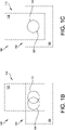
- FIG. 1B illustrates one example of the system 100 being viewed under fluoroscopy when there is a misalignment between the fluoroscopic device (e.g., X-ray and/or C-arm) and an anatomical plane
- FIG. 1C illustrates one example of the system 100 being view under fluoroscopy when the fluoroscopic device (e.g., X-ray and/or C-arm) are aligned properly with an anatomical plane.
- the misalignment is identifiable when both alignment members 106, 114 are visible under fluoroscopy (FIG. 1B) and the fluoroscopic device is properly aligned with the system when the two alignment members 106, 114 appear as one (FIG. 1C).
- FIG. 2A illustrates another example of a system in accordance with some embodiments.
- System 200 includes a first component 202 having a body 204 supporting a first alignment member 206.
- a second component 210 has a body 212 supporting a second alignment member 214.
- the bodies 204, 212 of the first and second components 202, 210 may be formed from a radiolucent material such that the bodies 204, 212 are invisible or only partially visible when viewed under fluoroscopy as will be understood by one of ordinary skill in the art.
- first and second components 202, 210 are shown as being separate components, it should be understood that the first and second components may be configured as first and second portions of a common device (e.g., the same prosthesis, fixture, and/or jig), but disposed at a distance from one another.
- a common device e.g., the same prosthesis, fixture, and/or jig
- the first and second alignment members 206, 214 are formed from a radiopaque material such that the first and second alignment members may be visualized under fluoroscopy.
- the first and second alignment members 206, 214 have different complementary shapes. More particularly, alignment member 206 is shown as being in the shape of a circle and alignment member 214 is shown as being in the shape of a crosshair that is dimensioned to correspond to the shape of alignment member 206. It should be understood that although alignment member 206 is illustrated as being a circle and alignment member 214 is illustrated as a crosshair, alignment members 206, 214 may have other shapes or configurations.
- alignment member 206 may have another shape, such as a square, smaller ring, rectangle, triangle, etc., and/or alignment member 214 may take the form of a dot, circle, or other shape that is designed to provide an indication of alignment as will be understood by one of ordinary skill in the art.
- the radiodensity (or radiopacity) of alignment members 206, 214 may be the same or different.
- first and second components 202, 210 are described as each including a single alignment member, i.e., alignment members 206, 214, first and second components 202, 210 may include plural alignment members, which may be oriented in the same or different planes.
- first and second components 202, 210 may include one or more alignment members 206, 214 disposed in a first plane (e.g., coronal plane) and may also include one or more alignment members disposed in a second plane (e.g., sagittal or transverse plane).
- first and second alignment members 206, 214 may also vary.
- the alignment members 206, 214 may be embedded within the respective bodies 204, 212 of the first and second components 202, 210.
- the alignment members 206, 214 are affixed to a surface of the first and second components 202, 210, such as by using an adhesive or mechanical coupling.
- the first and second alignment members 206, 214 may be supported by the first and second components 202, 210 through different means.
- the first alignment member 206 may be embedded within body 204 of first component 202
- second alignment member 214 may be affixed to a surface of body 212 of second component 210.
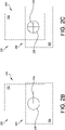
- FIG. 2B illustrates one example of the system 200 being viewed under fluoroscopy when there is a misalignment between the fluoroscopic device (e.g., X-ray and/or C-arm) and an anatomic plane
- FIG. 2C illustrates one example of the system 200 being view under fluoroscopy when the fluoroscopic device (e.g., X-ray, imaging device, and/or C-arm) is aligned properly with an anatomical plane.
- the misalignment is identifiable when alignment member 214 is not positioned properly with respect to alignment member 206, i.e., crosshair is not disposed within and encircled by the circle (FIG. 2B), and the fluoroscopic device is aligned properly with system 200 when alignment member 214 is disposed within and encircled by alignment member 206 (FIG. 2C).
- FIG. 3A illustrates another example of a system in accordance with some embodiments.
- System 300 includes a first component 302 having a body 304 supporting a first alignment member 306.
- a second component 310 has a body 312 supporting a second alignment member 314.
- the bodies 304, 312 of the first and second components 302, 310 may be formed from a radiolucent material such that the bodies 304, 312 are invisible or only partially visible when viewed under fluoroscopy as will be understood by one of ordinary skill in the art.
- first and second components 302, 310 are shown as being separate components, it should be understood that the first and second components may be configured as first and second portions of a common device (e.g., the same prosthesis, fixture, and/or jig), but disposed at a distance from one another.
- a common device e.g., the same prosthesis, fixture, and/or jig
- the first and second alignment members 306, 314 are formed from a radiopaque material such that the first and second alignment members may be visualized under fluoroscopy.
- the first and second alignment members 306, 314 have different complementary shapes. More particularly, alignment member 306 is shown as being in the shape of a circle and alignment member 314 is shown as being a dot that is sized and configured to fill the entirety of the circle of alignment member 306.
- the radiodensity (or radiopacity) of alignment members 306, 314 may be the same or different.
- first and second components 302, 310 are described as each including a single alignment member, i.e., alignment members 306, 314, first and second components 302, 310 may include plural alignment members, which may be oriented in the same or different planes.
- first and second components 302, 310 may include one or more alignment members 306, 314 disposed in a first plane (e.g., coronal plane) and may also include one or more alignment members disposed in a second plane (e.g., sagittal or transverse plane).
- first and second alignment members 306, 314 are supported by the first and second components 302, 310 also may vary.
- the alignment members 306, 314 may be embedded within the respective bodies 304, 312 of the first and second components 302, 210.
- the alignment members 306, 314 are affixed to a surface of the first and second components 302, 310, such as by using an adhesive or mechanical coupling.
- the first and second alignment members 306, 314 may be supported by the first and second components 302, 310 through different means.
- the first alignment member 306 may be embedded within body 304 of first component 302, and second alignment member 314 may be affixed to a surface of body 312 of second component 310.
- FIG. 3B illustrates one example of the system 300 being viewed under fluoroscopy when there is a misalignment between the fluoroscopic device (e.g., X-ray and/or C-arm) and an anatomical plane
- FIG. 3C illustrates one example of the system 300 being view under fluoroscopy when the fluoroscopic device (e.g., X-ray, imaging device, and/or C-arm) aligned properly with an anatomical plane.
- the misalignment is identifiable when alignment member 314 is not positioned properly with respect to alignment member 306, i.e., dot is not disposed within and fill the circle (FIG. 3B), and the fluoroscopic device is aligned properly with system 300 when alignment member 314 is disposed within and fills alignment member 306 (FIG. 3C).
- FIG. 4 illustrates another example of a system in accordance with some embodiments. More particularly, the alignment system provided in FIG. 4 includes an alignment adapter 402 that is sized and configured to engage another surgical device 30, such as the alignment guide 30 disclosed in U.S. Patent No. 9,402,640 , entitled "Alignment Guide with Embedded Features for Intra-Operative Fluoro-Checks," which is incorporated by reference herein in its entirety.
- an alignment adapter 402 that is sized and configured to engage another surgical device 30, such as the alignment guide 30 disclosed in U.S. Patent No. 9,402,640 , entitled "Alignment Guide with Embedded Features for Intra-Operative Fluoro-Checks," which is incorporated by reference herein in its entirety.
- Adapter 402 includes a body 404 that includes an enlarged planar surface 406 and a coupling mechanism 408.
- planar surface 406 is enlarged with respect to the rest of the body 404 and provides for enhanced visualization such that the alignment between the surgical device 30 and the fluoroscopic device 50 may be checked or confirmed as described below.
- Coupling mechanism 408 may take a variety of forms to facilitate the coupling of adapter 402 to surgical device 30.
- coupling mechanism 408 may the take the form of a channel 410 that is sized and configured to receive and/or engage at least a portion (e.g., the anterior protruding portion 36) of surgical device 30.
- coupling mechanism 408 may vary based on the characteristics of the device 30.
- Examples of other coupling mechanisms include, but are not limited to, a slot with dovetail connection, a detent, a hole for receiving a pin, and a protrusion designed to be inserted into a slot or hole defined by device 30, to list only a few possible examples.
- Coupling mechanism 408 is designed to engage device 30 such that planar surface 406 is oriented relative to device 30 in a predetermined manner.
- coupling mechanism 408 is sized and configured to engage device 30 such that planar surface is parallel to a longitudinal axis of a radiopaque member (e.g., radiopaque members 34a, 34b, 35 disclosed in U.S. Patent No. 9,402,640 ) supported by device 30.
- a radiopaque member e.g., radiopaque members 34a, 34b, 35 disclosed in U.S. Patent No. 9,402,640
- adapter 402 coupled to device 30, a surgeon, radiographic technician, or other individual may align the fluoroscopic device 50 with device 30 by visually determining whether the planar surface 406 of adapter 302 is oriented parallel to fluoroscopic device 50.
- the enlarged surface 406 provided by adapter 402 is easier to align with fluoroscopic device 50 compared to a surface feature of device 30.
- adapter 402 and surgical device 30 may include cooperative alignment members, such as the alignment members described above with reference to FIGS. 1A-1C, 2A-2C, and 3A-3C.
- FIGS. 5A-5C illustrates another example of an alignment device 500 in accordance with some embodiments. More particularly, FIG. 5A is a top side view of one example of an alignment device 500, FIG. 5B is a cross-sectional view of the device 500 taken along line 5B-5B in FIG. 5A, and FIG. 5C is a cross-sectional view of the device 500 taken along line 5C-5C in FIG. A.
- Alignment device 500 has a body 502 that may be formed from a radiolucent material.
- body 502 defines first and second apertures 504, 506 that are oriented at an angle with respect to one another.
- apertures 504, 506 may be orthogonally oriented relative to one another such that aperture 504 is disposed parallel to a first plane (e.g., coronal, medial, sagittal, or transverse plane) and aperture 506 is disposed parallel to a second plane that is different from the first plane (e.g., another of the coronal, medial, sagittal, and transverse planes).
- apertures 504, 506 may be disposed at other angles (e.g., oblique or obtuse angles) relative to one another. As best seen in FIGS. 5B and 5C, apertures 504, 506 intersect one another within body 502.
- liners 508, 510 are disposed within apertures 504, 506, respectively.
- Liners 506, 508 may be formed from a reflective material and be configured to direct light 54, which is provided by a laser, light emitting diode (LED), or illuminating device 52, along their lengths.
- the illuminating device 52 is supported by or coupled to an fluoroscopic device 50, which may be supported by or include a C-arm as will be understood by one of ordinary skill in the art.
- alignment device 500 is positioned either one a patient or coupled to another surgical instrument, such as a prosthetic, fixture, and/or jig.
- An illuminating device or light source 52 which is coupled to or provided by a C-arm and/or fluoroscopic device 50, directs light 54 into one of the apertures (e.g., aperture 504 as shown in FIGS. 5A-5C).
- the fluoroscopic device is properly aligned with the device 500, the light 54 is received within aperture 504 (and liner 508, if provided) and is visible to the surgeon via aperture 506 (and liner 510, if provided).
- the liners 508, 510 may reflect the light along their lengths to enable the light to be viewed by the surgeon, technician, or other individual 60 (FIG. 5C) and prevents the device 500 from being illuminated entirely by illuminating device 52.
- FIG. 5D illustrates another system in which alignment device 500 may be included.
- a light source 52 directs light into aperture 506 (and liner 510, if provided) and a camera or optical sensor 56 is provided on the fluoroscopic device 50 (e.g., X-ray lens, C-arm, etc.) to detect light exiting aperture 504 (guided by liner 508, if provided).
- the camera 56 is coupled to a control and image processing system 58, which may be configured to detect the light emanating from aperture 504 and move the C-arm and fluoroscopic device into position based on the light detected by camera or optical sensor 56.
- a control and image processing system is imaging system 200 disclosed in U.S. Patent No. 8,611,697 , which is incorporated by reference herein in its entirety.
- a system in some embodiments, includes a first component and a second component.
- the first component has a first body supporting a first alignment member.
- the second component has a second body supporting a second alignment member.
- the first and second alignment members are separated from another and are configured to provide an indication that a fluoroscopic device is properly aligned with an anatomical plane when viewed under fluoroscopy.
- the first component and the second component are respective portions of a common device.
- a shape of the first alignment member is the same as a shape of the second alignment member.
- a dimension of the first alignment member is the same as a dimension of the second alignment member.
- a radiopacity of the first alignment member is different from a radiopacity of the second alignment member.
- a shape of the first alignment member is different from a shape of the second alignment member.
- the shape of the first alignment member is complementary to the shape of the second alignment member.
- the shape of the first alignment member is circular.
- the second alignment member includes a crosshair.
- the shape of the second alignment member is a dot sized to fill an opening of the circular shape of the first alignment member.
- a method includes placing a first component supporting a first alignment member and a second component supporting a second alignment member relative to a patient, and aligning a fluoroscopic device with an anatomical plane using the first and second alignment members.
- aligning the fluoroscopic device with the anatomical plane includes viewing the first and second alignment members under fluoroscopy.
- the first and second alignment members appear as a single alignment member when the fluoroscopic device is aligned with the anatomical plane.
- the first and second alignment members have a complementary shape when the fluoroscopic device is aligned with the anatomical plane.
- a system in some embodiments, includes an alignment device having a body defining a first aperture and a second aperture.
- the first and second apertures are disposed at an angle with one another.
- the first and second apertures are in communication with one another such that light passes through the first and second apertures when a fluoroscopic device is aligned with an anatomical plane.
- a first liner is disposed within the first aperture.
- the first liner is configured to direct light along a length of the first aperture.
- a second liner is disposed within the second aperture.
- the second liner is configured to direct light along a length of the second aperture.
- a system includes a light source configured to direct light into at least one of the first aperture and the second aperture.
- the light source is coupled to a C-arm of a radiographic device.
- a system in some embodiments, includes an optical sensor coupled to a C-arm of a radiographic device.
- the optical detector is configured to detect light exiting at least one of the first aperture and the second aperture.
- a system includes a camera coupled to a C-arm of a radiographic device.
- the camera is configured to receive light from at least one of the first aperture and the second aperture.
- a method includes receiving light emitted from a light source in a first aperture defined by an alignment device, and directing the light from the first aperture defined by the alignment device to a second aperture defined by the alignment device such that light exits the alignment device from the second aperture.
- the second aperture is disposed at an angle with respect to the first aperture.
- the second aperture is disposed at an angle with respect to the first aperture.
- the light emitted from the light source is received within the first aperture when a fluoroscopic device is aligned with an anatomical axis.
- a method includes detecting light exiting the alignment device using an optical sensor.
- a method includes adjusting a position of a fluoroscopic device if light is not detected by the optical sensor.
- a method includes detecting light exiting the alignment device using a camera.
- a method includes adjusting a position of a fluoroscopic device if light is not detected by the camera.
- a system in some embodiments, includes a first surgical device and an alignment adapted.
- the first surgical device is configured to be coupled to a patient.
- the alignment adapter has a body including a planar surface and a coupling mechanism for coupling the alignment adapter to the first surgical device such that the planar surface is parallel to an anatomical plane when the first surgical device is coupled to the patient and the alignment adapter is coupled to the first surgical device.
- the coupling mechanism includes a channel sized and configured to receive at least a portion of the first surgical device.
- the coupling mechanism includes a detent sized and configured to engage the first surgical device.
- the coupling mechanism includes a slot having a dovetail that is sized and configured to engage a corresponding feature of the first surgical device.
- a method includes placing a first surgical device relative to a patient, coupling an alignment device to the first surgical device, and aligning a fluoroscopic device with the planar surface of the alignment device.
- the alignment device includes a planar surface.
- a method includes adjusting a position of the fluoroscopic device until the fluoroscopic device is aligned with the planar surface of the alignment device.
- the planar surface of the alignment device is parallel to an anatomical plane of the patient.
Landscapes
- Physics & Mathematics (AREA)
- Engineering & Computer Science (AREA)
- Health & Medical Sciences (AREA)
- Life Sciences & Earth Sciences (AREA)
- Electromagnetism (AREA)
- Medical Informatics (AREA)
- Nuclear Medicine, Radiotherapy & Molecular Imaging (AREA)
- Surgery (AREA)
- Remote Sensing (AREA)
- Radar, Positioning & Navigation (AREA)
- General Physics & Mathematics (AREA)
- Heart & Thoracic Surgery (AREA)
- Veterinary Medicine (AREA)
- Molecular Biology (AREA)
- Radiology & Medical Imaging (AREA)
- Animal Behavior & Ethology (AREA)
- General Health & Medical Sciences (AREA)
- Public Health (AREA)
- Biomedical Technology (AREA)
- Pathology (AREA)
- Optics & Photonics (AREA)
- High Energy & Nuclear Physics (AREA)
- Biophysics (AREA)
- Computer Networks & Wireless Communication (AREA)
- Oral & Maxillofacial Surgery (AREA)
- Gynecology & Obstetrics (AREA)
- Apparatus For Radiation Diagnosis (AREA)
Applications Claiming Priority (2)
| Application Number | Priority Date | Filing Date | Title |
|---|---|---|---|
| US202163208572P | 2021-06-09 | 2021-06-09 | |
| US17/661,196 US12196856B2 (en) | 2021-06-09 | 2022-04-28 | Alignment systems and methods |
Publications (2)
| Publication Number | Publication Date |
|---|---|
| EP4101415A2 true EP4101415A2 (de) | 2022-12-14 |
| EP4101415A3 EP4101415A3 (de) | 2023-05-31 |
Family
ID=81585556
Family Applications (1)
| Application Number | Title | Priority Date | Filing Date |
|---|---|---|---|
| EP22172072.5A Pending EP4101415A3 (de) | 2021-06-09 | 2022-05-06 | Ausrichtungssysteme und verfahren |
Country Status (2)
| Country | Link |
|---|---|
| US (2) | US12196856B2 (de) |
| EP (1) | EP4101415A3 (de) |
Citations (2)
| Publication number | Priority date | Publication date | Assignee | Title |
|---|---|---|---|---|
| US8611697B2 (en) | 2007-06-21 | 2013-12-17 | Surgix Ltd. | System for measuring the true dimensions and orientation of objects in a two dimensional image |
| US9402640B2 (en) | 2012-12-12 | 2016-08-02 | Wright Medical Technology, Inc. | Alignment guide with embedded features for intra-operative fluoro-checks |
Family Cites Families (203)
| Publication number | Priority date | Publication date | Assignee | Title |
|---|---|---|---|---|
| DE2236141B2 (de) | 1972-07-22 | 1976-07-08 | Fa. Waldemar Link, 2000 Hamburg | Teilprothese fuer das sprunggelenk eines menschen |
| GB1446593A (en) | 1973-01-12 | 1976-08-18 | Nat Res Dev | Endoprosthetic ankle joint devices |
| GB1447368A (en) | 1973-02-09 | 1976-08-25 | Nat Res Dev | Endo prosthetic ankle joint devices |
| US3872519A (en) | 1974-04-04 | 1975-03-25 | Nicholas J Giannestras | Total ankle prosthesis |
| US3886599A (en) | 1974-07-25 | 1975-06-03 | Schlein Louis Charles | Surgically implantable total ankle prosthesis |
| US3889300A (en) | 1974-08-28 | 1975-06-17 | Wright Mfg | Articulated two-part prosthesis replacing the ankle joint |
| US3975778A (en) | 1975-07-14 | 1976-08-24 | Newton Iii St Elmo | Total ankle arthroplasty |
| US3987500A (en) | 1976-01-28 | 1976-10-26 | Schlein Allen P | Surgically implantable total ankle prosthesis |
| US4021864A (en) | 1976-04-14 | 1977-05-10 | The Regents Of The University Of California | Ankle prosthesis |
| US4069518A (en) | 1976-08-31 | 1978-01-24 | Groth Jr Harry E | Total ankle prosthesis |
| CH607579A5 (de) | 1976-11-15 | 1978-09-15 | Sulzer Ag | |
| GB1579773A (en) | 1977-07-18 | 1980-11-26 | Nat Res Dev | Endoprosthetic bone joint devices |
| US4166292A (en) | 1977-09-08 | 1979-09-04 | Carbomedics, Inc. | Stress reinforced artificial joint prostheses |
| US4204284A (en) | 1977-11-16 | 1980-05-27 | Lord Corporation | Joint prosthesis with contoured pin |
| US4470158A (en) | 1978-03-10 | 1984-09-11 | Biomedical Engineering Corp. | Joint endoprosthesis |
| US4309778A (en) | 1979-07-02 | 1982-01-12 | Biomedical Engineering Corp. | New Jersey meniscal bearing knee replacement |
| US4578806A (en) | 1983-12-15 | 1986-03-25 | General Electric Company | Device for aligning cooperating X-ray systems |
| US4755185A (en) | 1987-01-27 | 1988-07-05 | Boehringer Mannheim Corporation | Prosthetic joint |
| US4968316A (en) | 1988-12-12 | 1990-11-06 | Hergenroeder Patrick T | Arthroscopic ankle joint distraction method |
| SE466937B (sv) | 1989-04-25 | 1992-05-04 | Branemark Per Ingvar | Foerankringsanordning foer till benvaevnad applicerbara proteser, spec ledmekanismer |
| US5326365A (en) | 1992-04-10 | 1994-07-05 | Alvine Franklin G | Ankle implant |
| US5423825A (en) | 1992-06-10 | 1995-06-13 | Levine; Andrew S. | Spinal fusion instruments and methods |
| US5354300A (en) | 1993-01-15 | 1994-10-11 | Depuy Inc. | Drill guide apparatus for installing a transverse pin |
| US5312412A (en) | 1993-02-03 | 1994-05-17 | Whipple Terry L | Fixation alignment guide for surgical use |
| US5476466A (en) | 1993-07-20 | 1995-12-19 | Zimmer, Inc. | Orthopaedic positioning instrument |
| US5674223A (en) | 1994-02-16 | 1997-10-07 | Joint Medical Products Corporation | Instrument for implanting a femoral knee prosthesis |
| US6517583B1 (en) | 2000-01-30 | 2003-02-11 | Diamicron, Inc. | Prosthetic hip joint having a polycrystalline diamond compact articulation surface and a counter bearing surface |
| US5885299A (en) | 1994-09-15 | 1999-03-23 | Surgical Dynamics, Inc. | Apparatus and method for implant insertion |
| US6033405A (en) | 1994-09-15 | 2000-03-07 | Surgical Dynamics, Inc. | Apparatus and method for implant insertion |
| DE19501069A1 (de) | 1995-01-16 | 1996-07-18 | Wolfgang Kloess | Lichtvisier |
| US5609642A (en) | 1995-02-15 | 1997-03-11 | Smith & Nephew Richards Inc. | Tibial trial prosthesis and bone preparation system |
| US5578039A (en) | 1995-02-15 | 1996-11-26 | Smith & Nephew Richards Inc. | Tibial resection instrumentation and surgical method |
| US5702468A (en) | 1995-03-09 | 1997-12-30 | Uresil Corporation | Carpal bone biaxially restrained prosthesis |
| US5766259A (en) | 1995-03-14 | 1998-06-16 | Sammarco; Giacomo J. | Total ankle prosthesis and method |
| JP3501542B2 (ja) | 1995-04-07 | 2004-03-02 | 富久 腰野 | 医用硬組織代替部材および人工関節 |
| US5735904A (en) | 1995-07-05 | 1998-04-07 | Pappas; Michael J. | Spacer for establishng prosthetic gap and ligamentous tension |
| US5634927A (en) | 1995-07-06 | 1997-06-03 | Zimmer, Inc. | Sizing plate and drill guide assembly for orthopaedic knee instrumentation |
| US5817097A (en) | 1995-08-03 | 1998-10-06 | Synvasive Technology, Inc. | Bone saw blade guide with magnet |
| US5601563A (en) | 1995-08-25 | 1997-02-11 | Zimmer, Inc. | Orthopaedic milling template with attachable cutting guide |
| US5716361A (en) | 1995-11-02 | 1998-02-10 | Masini; Michael A. | Bone cutting guides for use in the implantation of prosthetic joint components |
| FR2747302B1 (fr) | 1996-04-11 | 1998-09-11 | Tornier Sa | Prothese de cheville |
| US5880976A (en) | 1997-02-21 | 1999-03-09 | Carnegie Mellon University | Apparatus and method for facilitating the implantation of artificial components in joints |
| FR2760353B1 (fr) | 1997-03-10 | 1999-07-02 | Tornier Sa | Prothese de cheville |
| US6344043B1 (en) | 1997-11-18 | 2002-02-05 | Michael J. Pappas | Anterior-posterior femoral resection guide with set of detachable collets |
| US5935132A (en) | 1997-12-10 | 1999-08-10 | Johnson & Johnson Professional, Inc. | Surgical guide and cutting system |
| US6090145A (en) | 1997-12-10 | 2000-07-18 | Societe Industrielle De Combustible Nucleaire S I C N | Partial scaphoid implant and method of treating ailments of the scaphoid |
| WO2000004839A1 (en) | 1998-06-09 | 2000-02-03 | Nuvasive, Inc. | Spinal surgery guidance platform |
| ATE254893T1 (de) | 1998-09-11 | 2003-12-15 | Argomedical Ag | Implantierbare prothese mit zumindest zwei gegeneinander verstellbaren abschnitten sowie verwendung verstellbarer abschnitte |
| US6109672A (en) | 1998-10-09 | 2000-08-29 | Valeo Electrical Systems, Inc. | Combination window release and wiper system and method |
| US6063091A (en) | 1998-10-13 | 2000-05-16 | Stryker Technologies Corporation | Methods and tools for tibial intermedullary revision surgery and associated tibial components |
| US6689142B1 (en) | 1999-04-26 | 2004-02-10 | Scimed Life Systems, Inc. | Apparatus and methods for guiding a needle |
| IT1310371B1 (it) | 1999-05-13 | 2002-02-13 | Ist Ortopedici Rizzoli | Dispositivo di protesi per articolazione umana, in particolare perarticolazione della tibotarsica e relativo metodo di impianto. |
| FR2797178B1 (fr) | 1999-08-05 | 2002-02-22 | Tornier Sa | Implant malleolaire pour prothese partielle ou totale de cheville et materiel ancillaire de pose d'un tel implant |
| US6875235B2 (en) | 1999-10-08 | 2005-04-05 | Bret A. Ferree | Prosthetic joints with contained compressible resilient members |
| US6663669B1 (en) | 1999-10-22 | 2003-12-16 | Mark A Reiley | Ankle replacement system |
| US6673116B2 (en) | 1999-10-22 | 2004-01-06 | Mark A. Reiley | Intramedullary guidance systems and methods for installing ankle replacement prostheses |
| FR2800601B1 (fr) | 1999-11-05 | 2002-01-04 | Europ Foot Platform | Prothese de cheville |
| US6245109B1 (en) | 1999-11-18 | 2001-06-12 | Intellijoint Systems, Ltd. | Artificial joint system and method utilizing same for monitoring wear and displacement of artificial joint members |
| US6342056B1 (en) | 2000-02-04 | 2002-01-29 | Jean-Marc Mac-Thiong | Surgical drill guide and method for using the same |
| US20010053204A1 (en) * | 2000-02-10 | 2001-12-20 | Nassir Navab | Method and apparatus for relative calibration of a mobile X-ray C-arm and an external pose tracking system |
| JP5026650B2 (ja) | 2000-03-10 | 2012-09-12 | スミス アンド ネフュー インコーポレーテッド | 膝関節の関節形成装置 |
| US20030208280A1 (en) | 2000-04-21 | 2003-11-06 | Behrooz Tohidi | Wear resistant artificial joint |
| US7163541B2 (en) | 2002-12-03 | 2007-01-16 | Arthrosurface Incorporated | Tibial resurfacing system |
| US7678151B2 (en) | 2000-05-01 | 2010-03-16 | Ek Steven W | System and method for joint resurface repair |
| US7713305B2 (en) | 2000-05-01 | 2010-05-11 | Arthrosurface, Inc. | Articular surface implant |
| US8177841B2 (en) | 2000-05-01 | 2012-05-15 | Arthrosurface Inc. | System and method for joint resurface repair |
| US6679917B2 (en) | 2000-05-01 | 2004-01-20 | Arthrosurface, Incorporated | System and method for joint resurface repair |
| EP2314257B9 (de) | 2000-05-01 | 2013-02-27 | ArthroSurface, Inc. | System zur Gelenkoberflächenerneuerung |
| US6610067B2 (en) | 2000-05-01 | 2003-08-26 | Arthrosurface, Incorporated | System and method for joint resurface repair |
| US6478800B1 (en) | 2000-05-08 | 2002-11-12 | Depuy Acromed, Inc. | Medical installation tool |
| FR2808994B1 (fr) | 2000-05-22 | 2003-03-21 | Transysteme Sarl | Prothese d'articulation |
| US6478799B1 (en) | 2000-06-29 | 2002-11-12 | Richard V. Williamson | Instruments and methods for use in performing knee surgery |
| US6773460B2 (en) | 2000-12-05 | 2004-08-10 | Roger P. Jackson | Anterior variable expandable fusion cage |
| US6942670B2 (en) | 2000-12-27 | 2005-09-13 | Depuy Orthopaedics, Inc. | Prosthesis evaluation assembly and associated method |
| US6355045B1 (en) | 2000-12-28 | 2002-03-12 | Depuy Orthopaedics, Inc. | Method and apparatus for surgically preparing a tibia for implantation of a prosthetic implant component which has an offset stem |
| US20020173853A1 (en) | 2001-05-17 | 2002-11-21 | Corl Harry E. | Movable joint and method for coating movable joints |
| AUPR597701A0 (en) | 2001-06-28 | 2001-07-19 | Portland Orthopaedics Pty Limited | Joint prosthesis |
| US7618421B2 (en) | 2001-10-10 | 2009-11-17 | Howmedica Osteonics Corp. | Tools for femoral resection in knee surgery |
| KR100764974B1 (ko) | 2002-03-08 | 2007-10-08 | 발데마르 링크 게엠베하 운트 코.카게 | 발목 관절 내부 인공 삽입물 |
| US6875222B2 (en) | 2002-03-12 | 2005-04-05 | Depuy Products, Inc. | Blade for resection of bone for prosthesis implantation, blade stop and method |
| US7615082B2 (en) | 2002-03-22 | 2009-11-10 | Hjs Gelenk System Gmbh | Artificial joint |
| US6863691B2 (en) | 2002-04-29 | 2005-03-08 | Timothy J. Short | Ankle implant |
| US8801720B2 (en) | 2002-05-15 | 2014-08-12 | Otismed Corporation | Total joint arthroplasty system |
| US20030236522A1 (en) | 2002-06-21 | 2003-12-25 | Jack Long | Prosthesis cavity cutting guide, cutting tool and method |
| US7025790B2 (en) | 2002-06-27 | 2006-04-11 | Concepts In Medicine Iii, L.L.C. | Ankle joint prosthesis and its method of implantation |
| US6645215B1 (en) | 2002-08-07 | 2003-11-11 | Howmedica Osteonics Corp. | Tibial rotation guide |
| US20040039394A1 (en) | 2002-08-26 | 2004-02-26 | Conti Stephen F. | Ankle fusion guide and method |
| US20040068322A1 (en) | 2002-10-04 | 2004-04-08 | Ferree Bret A. | Reduced-friction artificial joints and components therefor |
| US7252684B2 (en) | 2002-11-06 | 2007-08-07 | Southwest Research Institute | Ceramic in replacement components |
| US6939380B2 (en) | 2002-12-23 | 2005-09-06 | Depuy Products, Inc. | Mobile talar component for total ankle replacement implant |
| US7011687B2 (en) | 2003-01-06 | 2006-03-14 | Depuy Products, Inc. | Ankle prosthesis with a front loading bearing and associated method |
| US20040167631A1 (en) | 2003-02-21 | 2004-08-26 | Kenny Luchesi | Fixation surface for ankle prosthesis |
| US20040186585A1 (en) | 2003-03-21 | 2004-09-23 | Lawrence Feiwell | Sphere-on-sphere ankle prosthesis |
| US7238190B2 (en) | 2003-03-28 | 2007-07-03 | Concepts In Medicine Iii, Llc | Surgical apparatus to allow replacement of degenerative ankle tissue |
| US7481814B1 (en) | 2003-07-28 | 2009-01-27 | Biomet Manufacturing Corporation | Method and apparatus for use of a mill or reamer |
| US7153325B2 (en) | 2003-08-01 | 2006-12-26 | Ultra-Kinetics, Inc. | Prosthetic intervertebral disc and methods for using the same |
| JP4191194B2 (ja) | 2003-08-27 | 2008-12-03 | ヴァルデマール・リンク・ゲゼルシャフト・ミット・ベシュレンクテル・ハフツング・ウント・コムパニー・コマンディットゲゼルシャフト | 足関節エンドプロテーゼ |
| US7534270B2 (en) | 2003-09-03 | 2009-05-19 | Integra Lifesciences Corporation | Modular total ankle prosthesis apparatuses and methods |
| GB0322084D0 (en) | 2003-09-22 | 2003-10-22 | Depuy Int Ltd | A drill guide assembly |
| WO2005037135A2 (en) | 2003-10-14 | 2005-04-28 | The University Of Iowa Research Foundation | Ankle prosthesis and method for implanting ankle prosthesis |
| WO2005051231A2 (en) | 2003-11-20 | 2005-06-09 | Arthrosurface, Inc. | Retrograde delivery of resurfacing devices |
| US7625379B2 (en) | 2004-01-26 | 2009-12-01 | Warsaw Orthopedic, Inc. | Methods and instrumentation for inserting intervertebral grafts and devices |
| US7485147B2 (en) | 2004-02-13 | 2009-02-03 | Pappas Michael J | Ankle prosthesis including tibial component having peripheral wall for preventing the formation of bone cysts |
| US7323012B1 (en) | 2004-03-17 | 2008-01-29 | Biomet Manufacturing Corp. | Ankle implant |
| US7803158B2 (en) | 2004-03-26 | 2010-09-28 | Depuy Products, Inc. | Navigated pin placement for orthopaedic procedures |
| US7763080B2 (en) | 2004-04-30 | 2010-07-27 | Depuy Products, Inc. | Implant system with migration measurement capacity |
| US20050251147A1 (en) | 2004-05-07 | 2005-11-10 | Novak Vincent P | Open wedge osteotomy system and surgical method |
| US20050288792A1 (en) | 2004-06-23 | 2005-12-29 | Landes Mark D | Modular ankle prosthesis and associated method |
| JP2008504107A (ja) | 2004-06-28 | 2008-02-14 | アースロサーフィス・インコーポレーテッド | 関節面交換用システム |
| US9237958B2 (en) | 2004-06-30 | 2016-01-19 | Synergy Disc Replacement Inc. | Joint prostheses |
| US20060009857A1 (en) | 2004-07-08 | 2006-01-12 | Gibbs Phillip M | Method and apparatus for surface hardening implants |
| US8167888B2 (en) | 2004-08-06 | 2012-05-01 | Zimmer Technology, Inc. | Tibial spacer blocks and femoral cutting guide |
| WO2006023824A2 (en) | 2004-08-19 | 2006-03-02 | Kinetikos Medical Incorporated | Ankle prosthesis and method of curved resection |
| AT502926B1 (de) | 2004-11-08 | 2011-04-15 | Alphamed Medizintechnik Fischer Gmbh | Sprunggelenksprothesenelemente |
| US7648508B2 (en) | 2004-11-30 | 2010-01-19 | Stryker Trauma S.A. | Bone plating implants, instruments and methods |
| US20070038303A1 (en) | 2006-08-15 | 2007-02-15 | Ebi, L.P. | Foot/ankle implant and associated method |
| US7935119B2 (en) | 2005-01-31 | 2011-05-03 | Ibalance Medical, Inc. | Method for performing an open wedge, high tibial osteotomy |
| US8317797B2 (en) | 2005-02-08 | 2012-11-27 | Rasmussen G Lynn | Arthroplasty systems and methods for optimally aligning and tensioning a knee prosthesis |
| WO2006088684A1 (en) | 2005-02-17 | 2006-08-24 | Zimmer Technology, Inc. | Tibial trialing assembly and method of trialing a tibial implant |
| CA2601090C (en) | 2005-03-14 | 2013-08-20 | Inbone Technologies, Inc. | Ankle replacement system |
| US20060247788A1 (en) | 2005-03-31 | 2006-11-02 | The Regents Of The University Of California | Total ankle arthroplasty |
| US20060235541A1 (en) | 2005-04-15 | 2006-10-19 | Zimmer Technology, Inc. | Bearing implant |
| US20070100346A1 (en) | 2005-10-27 | 2007-05-03 | Wyss Joseph G | Support for locating instrument guides |
| AU2006326312A1 (en) | 2005-12-12 | 2007-06-21 | Link America, Inc. | Endoprosthesis with intermediate part |
| EP1981439A4 (de) | 2006-01-20 | 2013-02-06 | Gmbh Synthes | Verfahren zur vorbereitung des fussknöchelersatzes, gelenkprothese und schnittausrichtungsvorrichtung für den einsatz bei der durchführung eines arthroplastikverfahrens |
| FR2896404B1 (fr) | 2006-01-24 | 2008-02-29 | Tornier Sas | Ensemble d'instrumentation chirurgicale pour poser une prothese de cheville |
| US9808262B2 (en) | 2006-02-15 | 2017-11-07 | Howmedica Osteonics Corporation | Arthroplasty devices and related methods |
| US10357184B2 (en) | 2012-06-21 | 2019-07-23 | Globus Medical, Inc. | Surgical tool systems and method |
| US9011441B2 (en) | 2006-02-17 | 2015-04-21 | Paradigm Spine, L.L.C. | Method and system for performing interspinous space preparation for receiving an implant |
| US8092465B2 (en) | 2006-06-09 | 2012-01-10 | Biomet Manufacturing Corp. | Patient specific knee alignment guide and associated method |
| US8608748B2 (en) | 2006-02-27 | 2013-12-17 | Biomet Manufacturing, Llc | Patient specific guides |
| JP2009531078A (ja) | 2006-03-02 | 2009-09-03 | タラス メディカル, インコーポレイテッド | 人工骨 |
| GB0606837D0 (en) | 2006-04-05 | 2006-05-17 | Depuy Int Ltd | Cutting guide instrument |
| US20080015602A1 (en) | 2006-06-22 | 2008-01-17 | Howmedica Osteonics Corp. | Cutting block for bone resection |
| EP2063817A4 (de) | 2006-09-15 | 2012-04-18 | Pioneer Surgical Technology Inc | Gelenkarthroplastie-vorrichtung mit beweglichen elementen |
| FR2906999B1 (fr) | 2006-10-13 | 2009-06-05 | Tornier Sas | Ensemble prothetique de cheville |
| US9278006B2 (en) | 2006-10-26 | 2016-03-08 | European Foot Platform Sc | Ankle prosthesis with neutral position adjustment |
| ES2609389T3 (es) | 2006-11-17 | 2017-04-20 | Scyon Orthopaedics Ag | Geometría para reducir el desgaste de articulaciones en reemplazos totales de articulaciones |
| WO2008073999A2 (en) | 2006-12-12 | 2008-06-19 | Vladimir Alexander | Laser assisted total joint arthroplasty |
| BRPI0721117A2 (pt) | 2006-12-15 | 2014-06-03 | Synthes Gmbh | Guia de osteotomia para cortar um osso, e, método |
| US7909882B2 (en) | 2007-01-19 | 2011-03-22 | Albert Stinnette | Socket and prosthesis for joint replacement |
| GB2448740B (en) | 2007-04-26 | 2012-03-14 | Derek James Wallace Mcminn | Alignment device |
| EP2157926B1 (de) | 2007-05-14 | 2015-04-22 | Queen's University At Kingston | Patientenspezifisches chirurgisches führungswerkzeug |
| WO2008151644A1 (de) | 2007-06-12 | 2008-12-18 | Link America, Inc. | Endoprothese mit balliger gestaltung |
| WO2009015009A1 (en) | 2007-07-20 | 2009-01-29 | Talus Medical, Inc. | Methods and devices for deploying biological implants |
| US20110035018A1 (en) | 2007-09-25 | 2011-02-10 | Depuy Products, Inc. | Prosthesis with composite component |
| US8632600B2 (en) | 2007-09-25 | 2014-01-21 | Depuy (Ireland) | Prosthesis with modular extensions |
| US8715359B2 (en) | 2009-10-30 | 2014-05-06 | Depuy (Ireland) | Prosthesis for cemented fixation and method for making the prosthesis |
| US10398561B2 (en) | 2007-09-26 | 2019-09-03 | DePuy Synthes Products, Inc. | Talar implant system and method |
| US20090105840A1 (en) | 2007-10-18 | 2009-04-23 | Inbone Technologies, Inc. | Fibular stiffener and bony defect replacer |
| US20090105767A1 (en) | 2007-10-18 | 2009-04-23 | Inbone Technologies, Inc. | Total joint subsidence protector |
| JP5231574B2 (ja) * | 2008-01-28 | 2013-07-10 | リフレクティブ エックス−レイ オプティクス エルエルシー | X線撮影法によるx線撮像のための光学位置合わせシステムおよび位置合わせ方法 |
| WO2009111481A1 (en) | 2008-03-03 | 2009-09-11 | Arthrosurface Incorporated | Bone resurfacing system and method |
| US9168065B2 (en) | 2008-04-30 | 2015-10-27 | Moximed, Inc. | Ball and socket assembly |
| GB0809721D0 (en) | 2008-05-28 | 2008-07-02 | Univ Bath | Improvements in or relating to joints and/or implants |
| WO2009155111A1 (en) | 2008-05-30 | 2009-12-23 | Wright Medical Technology, Inc. | Drill guide assembly |
| AU2009262113A1 (en) | 2008-06-25 | 2009-12-30 | Small Bone Innovations, Inc. | Surgical instrumentation and methods of use for implanting a prothesis |
| US8012217B2 (en) | 2008-07-03 | 2011-09-06 | Fellowship of Orthopaedic Researchers, LLC | Talar implants and methods of use |
| US20100057216A1 (en) | 2008-07-23 | 2010-03-04 | Jamy Gannoe | System and method for joint resurfacing with dynamic fixation |
| US9808345B2 (en) | 2008-07-24 | 2017-11-07 | Iorthopedics, Inc. | Resilient arthroplasty device |
| JP2010075697A (ja) | 2008-09-22 | 2010-04-08 | Buechel-Pappas Trust | 適合−非適合の人工関節面を組み合わせてなる固定ベアリング式の人工関節 |
| US9017334B2 (en) | 2009-02-24 | 2015-04-28 | Microport Orthopedics Holdings Inc. | Patient specific surgical guide locator and mount |
| US8808303B2 (en) | 2009-02-24 | 2014-08-19 | Microport Orthopedics Holdings Inc. | Orthopedic surgical guide |
| DE102009011648A1 (de) | 2009-03-04 | 2010-09-09 | Advanced Medical Technologies Ag | Implantatsystem mit Auflageelementen |
| US8337503B2 (en) | 2009-04-13 | 2012-12-25 | George John Lian | Custom radiographically designed cutting guides and instruments for use in total ankle replacement surgery |
| US8475463B2 (en) | 2009-04-13 | 2013-07-02 | George J. Lian | Systems and instrumentalities for use in total ankle replacement surgery |
| US20120277745A1 (en) | 2009-04-21 | 2012-11-01 | Emmanuel Lizee | Systems and methods for positioning a foot in ankle arthrodesis |
| US8268007B2 (en) | 2009-06-26 | 2012-09-18 | The Cleveland Clinic Foundation | Multi-piece prosthetic joint component |
| US9510949B2 (en) | 2009-06-26 | 2016-12-06 | The Cleveland Clinic Foundation | Prosthetic joint component with rotation-regulating structure |
| DE102009031269B4 (de) | 2009-06-30 | 2013-07-25 | Universität Rostock | Vorrichtung zur In-situ-Fräsung von Gelenkflächen |
| US20110035019A1 (en) | 2009-07-09 | 2011-02-10 | Wright State University | Total ankle replacement system |
| WO2011008739A2 (en) | 2009-07-14 | 2011-01-20 | Medicinelodge, Inc. Dba Imds Co-Innovation | Joint arthrodesis and arthroplasty |
| GB0913674D0 (en) | 2009-08-06 | 2009-09-16 | Depuy Ireland | Surgical instrument and system of surgical instrument |
| EP3158976A1 (de) | 2009-11-16 | 2017-04-26 | New York Society for the Ruptured and Crippled Maintaining the Hospital for Special Surgery | Prothetische kondylusgelenke mit gelenkigen lagerflächen mit translationskontaktstelle während der rotation |
| EP2501303B1 (de) | 2009-11-20 | 2020-02-12 | Zimmer Knee Creations, Inc. | Navigations- und positionierungsinstrumente zur gelenkreparatur |
| EP2512354A4 (de) | 2009-12-18 | 2015-09-09 | Biomimedica Inc | Verfahren, vorrichtung und system zum schaben und formen eines gelenks |
| US9492281B2 (en) | 2010-02-19 | 2016-11-15 | European Foot Platform Sc | Ankle prosthesis with simplified adjustment |
| US8303667B2 (en) | 2010-03-02 | 2012-11-06 | Alastair Younger | Fastening system for prostheses |
| US8827554B2 (en) * | 2010-04-13 | 2014-09-09 | Carestream Health, Inc. | Tube alignment for mobile radiography system |
| US8591596B2 (en) | 2010-05-28 | 2013-11-26 | DePuy Synthes Products, LLC | Semi-constrained ankle prosthesis having a rotating bearing insert |
| GB2480846B (en) | 2010-06-03 | 2017-04-19 | Biomet Uk Healthcare Ltd | Guiding tool |
| US8647391B2 (en) | 2010-07-07 | 2014-02-11 | Global Orthopaedic Solutions Llc | Malleolar replacement devices |
| US20120010718A1 (en) | 2010-07-08 | 2012-01-12 | Still Gregory P | Partial ankle joint replacement implant |
| US8690956B2 (en) | 2010-08-23 | 2014-04-08 | Fellowship Of Orthopaedic Researchers, Inc. | Talar implants and methods of use |
| US10531897B2 (en) | 2010-08-26 | 2020-01-14 | Moximed, Inc. | Implantable device for relieving ankle pain |
| US8940046B2 (en) | 2010-10-01 | 2015-01-27 | Maxx Orthopedics, Inc. | Method of implanting a prosthesis device using bone cement in liquid form |
| US8911444B2 (en) | 2010-11-02 | 2014-12-16 | Zimmer, Inc. | Composite surgical instrument |
| US8668743B2 (en) | 2010-11-02 | 2014-03-11 | Adam D. Perler | Prosthetic device with multi-axis dual bearing assembly and methods for resection |
| US9023051B2 (en) | 2011-02-22 | 2015-05-05 | Zimmer Knee Creations, Inc. | Navigation and positioning systems and guide instruments for joint repair |
| US9186154B2 (en) | 2011-03-17 | 2015-11-17 | Zimmer, Inc. | Patient-specific instruments for total ankle arthroplasty |
| US20120245701A1 (en) | 2011-03-24 | 2012-09-27 | Rudolf Zak | Hemi Ankle Implant |
| US20120271430A1 (en) | 2011-04-22 | 2012-10-25 | Medicinelodge, Inc. Dba Imds Co-Innovation | Ankle arthroplasty |
| FR2986415A1 (fr) | 2012-02-06 | 2013-08-09 | Tornier Sa | Ensemble d'instrumentation chirurgicale pour poser une prothese de cheville |
| CA2836651C (en) | 2012-12-27 | 2016-03-22 | Wright Medical Technology, Inc. | Ankle replacement system and method |
| US10080573B2 (en) | 2012-12-27 | 2018-09-25 | Wright Medical Technology, Inc. | Ankle replacement system and method |
| CA2904652C (en) | 2013-03-14 | 2021-11-02 | Wright Medical Technology, Inc. | Ankle replacement system and method |
| US10433911B2 (en) | 2013-09-18 | 2019-10-08 | iMIRGE Medical INC. | Optical targeting and visualization of trajectories |
| WO2016195684A1 (en) * | 2015-06-04 | 2016-12-08 | Siemens Healthcare Gmbh | Apparatus and methods for a projection display device on x-ray imaging devices |
| US9672607B2 (en) | 2015-10-08 | 2017-06-06 | Biosense Webster (Israel) Ltd. | Identification and registration of multi-marker jig |
| US11540767B2 (en) | 2017-07-03 | 2023-01-03 | Globus Medical Inc. | Intraoperative alignment assessment system and method |
| US10653432B2 (en) | 2018-08-10 | 2020-05-19 | Wright Medical Technology, Inc. | Osteotomy guide |
| CA3122698A1 (en) | 2018-12-13 | 2020-06-18 | Paragon 28, Inc. | Distractors having attachable paddles, impaction devices, and methods for use in total ankle replacement |
| WO2021055230A1 (en) * | 2019-09-19 | 2021-03-25 | Akalana Management Llc | Optical systems with low resolution peripheral displays |
-
2022
- 2022-04-28 US US17/661,196 patent/US12196856B2/en active Active
- 2022-05-06 EP EP22172072.5A patent/EP4101415A3/de active Pending
-
2024
- 2024-11-26 US US18/960,387 patent/US20250085425A1/en active Pending
Patent Citations (2)
| Publication number | Priority date | Publication date | Assignee | Title |
|---|---|---|---|---|
| US8611697B2 (en) | 2007-06-21 | 2013-12-17 | Surgix Ltd. | System for measuring the true dimensions and orientation of objects in a two dimensional image |
| US9402640B2 (en) | 2012-12-12 | 2016-08-02 | Wright Medical Technology, Inc. | Alignment guide with embedded features for intra-operative fluoro-checks |
Also Published As
| Publication number | Publication date |
|---|---|
| US12196856B2 (en) | 2025-01-14 |
| US20220397670A1 (en) | 2022-12-15 |
| EP4101415A3 (de) | 2023-05-31 |
| US20250085425A1 (en) | 2025-03-13 |
Similar Documents
| Publication | Publication Date | Title |
|---|---|---|
| EP3445267B1 (de) | Verfahren und system zur registrierungsprüfung | |
| EP2593023B1 (de) | Chirurgisches zielsystem und -verfahren | |
| EP1430842B1 (de) | Chirurgisches Instrument | |
| US6267502B1 (en) | Alignment verification device and method of using the same with a visual light beam and an x-ray | |
| JP6138670B2 (ja) | 手術中の蛍光透視検査のために備えられた形状を有する整列ガイド | |
| EP1430841B1 (de) | Chirurgisches Instrument | |
| CA2160237C (en) | Dual radiation targeting system | |
| JP5972852B2 (ja) | 透視診断を用いた手術中のインプラントテンプレート機器 | |
| US20170143433A1 (en) | Systems, methods and devices for image registration and surgical localization | |
| US20040064148A1 (en) | Navigation of medical instrument | |
| US20100177185A1 (en) | Surgical microscope with integrated structured illumination | |
| US20070299334A1 (en) | Medical instrument with a touch-sensitive tip and light emission source | |
| US20070297572A1 (en) | X-ray shielding device | |
| JP2005279263A (ja) | コンピュータ支援式ナビゲーション・システムにおいてインプラントを登録するシステムおよび方法 | |
| US20050085822A1 (en) | Surgical navigation system component fault interfaces and related processes | |
| US6855152B2 (en) | Laser pointer | |
| US12196856B2 (en) | Alignment systems and methods | |
| US20080281330A1 (en) | Medical Securing Member Placement System | |
| KR20160126328A (ko) | 직관적인 정렬을 위한 포지셔닝 가이드를 갖는 ct 촬영 장치 | |
| KR20100079820A (ko) | 수술용 가이드 및 수술용 가이드 어셈블리 | |
| EP4563198A2 (de) | Bezugsrahmen und stützvorrichtung | |
| EP4585157A1 (de) | Röntgensystem und verfahren zur vorbereitung von röntgenuntersuchungen | |
| US20120281809A1 (en) | Indicator unit |
Legal Events
| Date | Code | Title | Description |
|---|---|---|---|
| PUAI | Public reference made under article 153(3) epc to a published international application that has entered the european phase |
Free format text: ORIGINAL CODE: 0009012 |
|
| STAA | Information on the status of an ep patent application or granted ep patent |
Free format text: STATUS: REQUEST FOR EXAMINATION WAS MADE |
|
| 17P | Request for examination filed |
Effective date: 20220506 |
|
| AK | Designated contracting states |
Kind code of ref document: A2 Designated state(s): AL AT BE BG CH CY CZ DE DK EE ES FI FR GB GR HR HU IE IS IT LI LT LU LV MC MK MT NL NO PL PT RO RS SE SI SK SM TR |
|
| RIC1 | Information provided on ipc code assigned before grant |
Ipc: A61B 17/00 20060101ALI20230117BHEP Ipc: A61B 90/00 20160101AFI20230117BHEP |
|
| PUAL | Search report despatched |
Free format text: ORIGINAL CODE: 0009013 |
|
| AK | Designated contracting states |
Kind code of ref document: A3 Designated state(s): AL AT BE BG CH CY CZ DE DK EE ES FI FR GB GR HR HU IE IS IT LI LT LU LV MC MK MT NL NO PL PT RO RS SE SI SK SM TR |
|
| RIC1 | Information provided on ipc code assigned before grant |
Ipc: A61B 17/00 20060101ALI20230426BHEP Ipc: A61B 90/00 20160101AFI20230426BHEP |
|
| RBV | Designated contracting states (corrected) |
Designated state(s): AL AT BE BG CH CY CZ DE DK EE ES FI FR GB GR HR HU IE IS IT LI LT LU LV MC MK MT NL NO PL PT RO RS SE SI SK SM TR |
|
| STAA | Information on the status of an ep patent application or granted ep patent |
Free format text: STATUS: EXAMINATION IS IN PROGRESS |
|
| 17Q | First examination report despatched |
Effective date: 20240919 |