EP4100703B1 - Procédé pour produire un système de mesure de poids - Google Patents
Procédé pour produire un système de mesure de poids Download PDFInfo
- Publication number
- EP4100703B1 EP4100703B1 EP21700260.9A EP21700260A EP4100703B1 EP 4100703 B1 EP4100703 B1 EP 4100703B1 EP 21700260 A EP21700260 A EP 21700260A EP 4100703 B1 EP4100703 B1 EP 4100703B1
- Authority
- EP
- European Patent Office
- Prior art keywords
- lever
- section
- fixing bolt
- cross
- weighing system
- Prior art date
- Legal status (The legal status is an assumption and is not a legal conclusion. Google has not performed a legal analysis and makes no representation as to the accuracy of the status listed.)
- Active
Links
Images


Classifications
-
- G—PHYSICS
- G01—MEASURING; TESTING
- G01G—WEIGHING
- G01G7/00—Weighing apparatus wherein the balancing is effected by magnetic, electromagnetic, or electrostatic action, or by means not provided for in the preceding groups
- G01G7/02—Weighing apparatus wherein the balancing is effected by magnetic, electromagnetic, or electrostatic action, or by means not provided for in the preceding groups by electromagnetic action
-
- G—PHYSICS
- G01—MEASURING; TESTING
- G01G—WEIGHING
- G01G21/00—Details of weighing apparatus
- G01G21/24—Guides or linkages for ensuring parallel motion of the weigh-pans
- G01G21/244—Guides or linkages for ensuring parallel motion of the weigh-pans combined with flexure-plate fulcrums
-
- B—PERFORMING OPERATIONS; TRANSPORTING
- B29—WORKING OF PLASTICS; WORKING OF SUBSTANCES IN A PLASTIC STATE IN GENERAL
- B29C—SHAPING OR JOINING OF PLASTICS; SHAPING OF MATERIAL IN A PLASTIC STATE, NOT OTHERWISE PROVIDED FOR; AFTER-TREATMENT OF THE SHAPED PRODUCTS, e.g. REPAIRING
- B29C64/00—Additive manufacturing, i.e. manufacturing of three-dimensional [3D] objects by additive deposition, additive agglomeration or additive layering, e.g. by 3D printing, stereolithography or selective laser sintering
- B29C64/30—Auxiliary operations or equipment
-
- B—PERFORMING OPERATIONS; TRANSPORTING
- B29—WORKING OF PLASTICS; WORKING OF SUBSTANCES IN A PLASTIC STATE IN GENERAL
- B29C—SHAPING OR JOINING OF PLASTICS; SHAPING OF MATERIAL IN A PLASTIC STATE, NOT OTHERWISE PROVIDED FOR; AFTER-TREATMENT OF THE SHAPED PRODUCTS, e.g. REPAIRING
- B29C69/00—Combinations of shaping techniques not provided for in a single one of main groups B29C39/00 - B29C67/00, e.g. associations of moulding and joining techniques; Apparatus therefore
- B29C69/001—Combinations of shaping techniques not provided for in a single one of main groups B29C39/00 - B29C67/00, e.g. associations of moulding and joining techniques; Apparatus therefore a shaping technique combined with cutting, e.g. in parts or slices combined with rearranging and joining the cut parts
-
- B—PERFORMING OPERATIONS; TRANSPORTING
- B33—ADDITIVE MANUFACTURING TECHNOLOGY
- B33Y—ADDITIVE MANUFACTURING, i.e. MANUFACTURING OF THREE-DIMENSIONAL [3-D] OBJECTS BY ADDITIVE DEPOSITION, ADDITIVE AGGLOMERATION OR ADDITIVE LAYERING, e.g. BY 3-D PRINTING, STEREOLITHOGRAPHY OR SELECTIVE LASER SINTERING
- B33Y40/00—Auxiliary operations or equipment, e.g. for material handling
- B33Y40/20—Post-treatment, e.g. curing, coating or polishing
-
- B—PERFORMING OPERATIONS; TRANSPORTING
- B29—WORKING OF PLASTICS; WORKING OF SUBSTANCES IN A PLASTIC STATE IN GENERAL
- B29L—INDEXING SCHEME ASSOCIATED WITH SUBCLASS B29C, RELATING TO PARTICULAR ARTICLES
- B29L2031/00—Other particular articles
- B29L2031/752—Measuring equipment
Definitions
- a generic gravimetric measuring device is known from JP 2017-161299 A .
- Gravimetric measuring devices in particular electronic gravimetric measuring devices, in particular those that work according to the principle of electromagnetic compensation (so-called EMF balances) are generally known to those skilled in the art. They regularly include a so-called weighing system, ie a complicated arrangement of folded levers, links and joints, which connects the load bearing of the measuring device to the actual weighing sensor, for example a coil-magnet system, to realize a displacement or force translation.
- a weighing system regularly includes a base that serves as a fixed reference point and is typically firmly connected to the housing within the measuring device and carries the fixed part of the sensor system, in particular the coil-magnet system. Lever and handlebars are movable relative to this base, in particular articulated on the base via joints.
- monolithic weighing systems are widespread in modern precision balances. They are characterized by the fact that all or at least almost all components of the weighing system are connected to one another in one piece, in particular are modeled out of a coherent block of material, typically aluminum. Such a monolithic weighing system is, for example, from EP 2 986 955 A1 known.
- the blank When producing such a weighing system, the blank takes on an increasingly delicate structure as the process progresses. Nevertheless, the forces acting on it and its components, through the processing itself and through its handling, in particular acceleration and tension forces, remain essentially the same. They are regularly significantly larger than the forces acting on the weighing system when operating a finished measuring device. Particularly in a late phase of the manufacturing process, there is therefore a risk of damage to the very sensitive joints, which are typically designed as thin-point joints, if levers and/or handlebars are stimulated to excessive deflections by said forces. To prevent this, it is customary to at least use the main lever of the system to be fixed or left fixed via material bridges at the base and to separate these material bridges only as a final processing step.
- levers, links and joints relative to the base are prevented until the final processing step.
- the lever that is still fixed is used as a reference to adjust the (usually optical) scanning sensor system for the lever position that is required to regulate the measuring current.
- the bolt is fixed to the base in the radial direction on the one hand; on the other hand, the lever is also fixed to the bolt in the radial direction, in particular perpendicular to its pivot axis. In this way, a relative movement of the lever to the base is prevented, so that no acceleration forces that occur during transport of the measuring device can lead to an excessive deflection of the lever that could damage the joints.
- a weighing system with an abutment pin is known. This is inserted into the long lever arm through an opening in the base body. It then sits in a form-fitting manner in the long lever arm, but it introduces play into the base body and thus limits the pivoting path of the long lever arm.
- the core of the invention consists in transferring the concept of lever fixation by means of fixing bolts, known from the context of transport security for complete gravimetric measuring devices, to the manufacturing process of the weighing system.
- the inventors have recognized that, despite completely different physical principles, the forces that cause damage to a measuring device during its transport are quite similar to the forces that cause damage to joints when the material bridges are pinched during the final manufacturing step of a weighing system.
- the present invention now proposes the novel use of a fixing bolt similar to the known transport bolt for fixing the lever during the manufacturing process of the weighing system, in particular during the final manufacturing step, i.e. during the separation of the material bridges between the lever and the base.
- the fixing bolt has at least two coaxial axial sections, namely a distal end section and a main section that adjoins it proximally, the cross section of the main section being at least partially the cross section of the lever opening corresponds and is larger than the cross section of the distal end section.
- This special dimensioning of the fixing bolt has no significance for the fundamental effect of the invention described above in the context of weighing system production.
- a simple, cylindrical pin would also be able to fulfill the described function as a fixing bolt for fixing the lever in a securing position.
- the special significance of the dimensioning mentioned is only revealed in the context of a generic gravimetric measuring device, which is characterized by the said dimensioning of the fixing bolt.
- Such a fixing bolt dimensioning allows in particular two axial positions of the fixing bolt, namely a rest position in which the fixing bolt, which is mounted in a form-fitting and axially displaceable manner in the wall opening, is advanced in such a way that its main section engages in a form-fitting manner in the lever opening.
- This rest position can also be referred to as the transport position and corresponds to the securing position described in the context of the manufacturing process during the final manufacturing step. It is characterized by a positive fixation of the lever on the base using the fixing bolt.
- a second working position made possible by said dimensioning of the fixing bolt is characterized in that the fixing bolt is retracted from the above-described rest position in such a way that its distal end section engages in the lever opening at a radial distance and its main section is positioned axially outside the lever opening .
- the positive connection between the fixing bolt main section and the wall opening is retained even in the working position.
- the working position is characterized by the fact that the lever can be pivoted relative to the base, but its deflection is limited by the distal end section of the fixing bolt which passes through its opening.
- a fixing bolt dimensioned in this way has a fourfold function: Firstly, it serves to reduce waste in the context of weighing system production; secondly, it serves to determine the lever as a reference for adjusting the scanning electronics; thirdly, it serves (in a fundamentally known manner) to secure the gravimetric measuring device for transport; and fourthly, it forms a safety stop for the lever during operation of the gravimetric measuring device.
- the cross-section is the functionally relevant cross-section, i.e. H. As a rule, this means the smallest clear cross section of an opening and the outer cross section of the specifically interacting axial section of a body.
- the expert will also recognize that the term crackdown does not necessarily imply a complete crackdown.
- the modeling of the blank as part of the weighing system manufacturing method according to the invention can, as is generally known, be carried out by subtractive processing of a monolithic material block.
- the modeling of the blank can also be carried out at least in some areas using an additive process.
- the entire weighing system is additive, for example, built using 3D printing.
- combinations of subtractive and additive process steps are also possible in the context of the present invention.
- the cross sections of the distal end region and the main section of the fixing bolt are preferably circular. Particularly in the context of a subtractive manufacturing process of the weighing system, such shapes can be created by simply drilling the blank. In the context of an additive modeling process for the weighing system, more complex cross-sectional shapes are also conceivable, which can then also provide anti-twist protection for the fixing bolt. In practice, however, the choice of circular cross-sectional shapes has proven successful.
- the basic shape of the fixing bolt according to the invention described above with a thinner distal end section and a thicker main section can be designed to be more complex in practice.
- the main section of the fixing bolt is divided into two axial subsections, namely a distal and a proximal subsection, the cross section of the proximal subsection being larger than the cross section of the distal subsection and the cross section of the wall breakthrough.
- the distal end section is of course provided with an even smaller cross section.
- the proximal subsection of the fixing bolt main section essentially serves to support it in the wall opening. Accordingly, their cross sections also match.
- the distal subsection of the fixing bolt main section serves the function of transport security and is the part of the fixation bolt that can be inserted in a form-fitting manner into the lever opening for the purpose of transport security.
- the distal end section serves the function of a safety stop during operation and engages with the lever opening at a radial distance.
- the distal end section extends to an opposite wall and into a recess located therein.
- This recess and the distal end section of the fixing bolt are preferably dimensioned so that the latter can engage in the former in a form-fitting manner. This ensures that the fixing bolt is mounted on two sides, which means In principle, greater stability of the fixing bolt positioning is enabled than with one-sided storage.
- the length dimension of the fixing bolt in particular is typically sufficiently small to achieve completely sufficient stability even when stored on one side.
- the transition between the distal end section and the main section of the fixing bolt is preferably provided with a chamfer.
- this chamfering causes the lever to be automatically transferred to the equilibrium position when the lever is slightly deflected from its equilibrium position. In particular, excessive loading of the lever with a lateral force is avoided.
- the axial displacement of the fixing bolt can be done manually, for example.
- the fixing bolt as is generally preferred, can be locked in different axial positions by means of a locking screw, which can be designed, for example, as a clamping screw or as a non-positive and positive locking screw. This largely eliminates the possibility of accidental displacement.
- the gravimetric measuring device further comprises a motor drive, by means of which the fixing bolt is axially displaceable.
- the motor control can be linked to the general scale control. This means that the fixing bolt displacement is completely prevented from any incorrect operation. Since the motor usually also fixes the fixing bolt in the respective target position, the above-mentioned locking screw can usually be dispensed with in this embodiment.
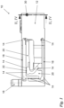
- FIG 1 shows, purely for the sake of orientation, a side view of an exemplary weighing system 10 in which the present invention is implemented.
- the weighing system 10 includes a base 12, which is to be understood as its fixed reference point.
- a load holder 16 which typically carries a weighing pan within a complete gravimetric measuring device, is articulated by means of links 18 via thin joints 14. Deflections of the load holder 16 are converted into one in by means of a multi-stage lever 20 Figure 1 not shown, in the functional gravimetric measuring device located inside the base 12. Individual sections of the lever 20 are connected to one another via further thin joints 14 and a coupling member 22.
- a free end region of the lever 20 is located in the area of the section line II, IV - II, IV and is in the Figures 2 to 5 shown in greater detail.
- the Figures 2 and 4 show the weighing system 10 in a sectional view along the section line II, IV - II, IV in two different positions, namely in an operating position ( Figure 2 ) and a rest position ( Figure 4 ).
- the Figures 3 and 5 each show enlarged representations corresponding to the magnification circles III in Figure 2 or V in Figure 4 .
- the Figures 2 to 5 should be discussed together below, as far as possible.
- the base 12 forms a lever channel 24 which extends between two walls 26, 28.
- the ones in the Figures 2 and 4 Wall 26 shown on the left will hereinafter simply be referred to as “wall” 26, whereas the one in the Figures 2 and 4 Wall 28 shown on the right should be addressed as the “opposite wall” 28.
- Both walls 26, 28 are penetrated by a through hole 30, which fulfills the function of a storage channel 32 in the interior of the wall 26 and, in the embodiment shown, fulfills no function within the opposite wall 28 and is only due to practical considerations of the manufacturing process.
- the lever 20 also has an opening 34, the cross section of which (at its narrowest point) is smaller than the cross section of the opening 32 in the wall 26, which serves as a storage channel.
- the lever opening 34 is provided with a blade-like taper, which defines its cross section (relevant to the invention) and ensures increased precision.
- the lever opening 34 could also be designed with a uniform cross section.
- a fixing bolt 36 is mounted in an axially displaceable manner in the wall opening 32.
- the fixing bolt 36 has a distal end section 38 with a smaller cross section and a main section 40 with a larger cross section.
- the main section 40 is divided into a distal subsection 40a and a proximal subsection 40b.
- the cross section of the distal end section 38 is smaller than the cross section of the lever opening 34; the cross section of the distal subsection 40a of the main section 40 corresponds to the cross section of the lever opening 34; and the cross section of the proximal subsection 40b of the main section 40 corresponds to the cross section of the wall opening 32.
- the fixing bolt 36 is mounted in the wall opening 32 so that it cannot tilt and is axially displaceable.
- the fixing bolt 36 In the in the Figures 2 and 3 In the operating position shown, the fixing bolt 36 is positioned so that its distal end section 38 passes through the narrowest point of the lever opening 34 at a complete distance.
- the lever 20 can therefore be pivoted to a limited extent relative to the base 12. This is completely sufficient, especially for scales that work according to the EMF principle, where only infinitesimal lever deflections occur during proper operation. However, if handled improperly, for example if a load is placed too hard on the weighing pan of the gravimetric measuring device, larger deflections can occur, which, however, are stopped in the operating position shown by the inner wall of the lever opening 34 striking the distal end section 38 of the fixing bolt 36 become. In this way, overloading of the sensitive thin joints 14 is prevented.
- the fixing bolt 36 can be advanced axially so that it is in the Figures 4 and 5 occupies the position shown.
- the main section 40 in particular its distal subsection 40a, passes through the lever opening 34 in a form-fitting manner. This prevents any deflection of the lever 20.
- the embodiment shown additionally has a locking screw 42 which opens into the bearing channel 32 and is designed as a simple clamping screw in the embodiment shown, with which the fixing bolt 36 can be clamped.
Landscapes
- Physics & Mathematics (AREA)
- Engineering & Computer Science (AREA)
- Chemical & Material Sciences (AREA)
- Manufacturing & Machinery (AREA)
- Materials Engineering (AREA)
- Mechanical Engineering (AREA)
- Electromagnetism (AREA)
- General Physics & Mathematics (AREA)
- Optics & Photonics (AREA)
- Weight Measurement For Supplying Or Discharging Of Specified Amounts Of Material (AREA)
- A Measuring Device Byusing Mechanical Method (AREA)
Claims (4)
- Procédé de fabrication d'un système de pesage (10), dans le cadre duquel- au moins une ébauche comportant+ une base (12) qui présente au moins une paroi (26), et+ un levier (20), articulé sur la base (12) par le biais d'une charnière de portion mince (14) et fixé sur la base (12) par le biais de ponts de matière et présentant une zone de levier adjacente à la paroi (26),est modelée,dans lequel la paroi (26) et la zone de levier qui lui est adjacente sont dotées chacune d'un percement (32, 34), qui sont alignés mutuellement, et- ensuite les ponts de matière sont séparés,caractérisé en ce queavant la séparation des ponts de matière, un boulon de fixation (36) est poussé dans les percements (32, 34) de telle sorte qu'il vient en prise par engagement positif dans les percements (32, 34) pendant la séparation des ponts de matière.
- Procédé selon la revendication 1,
caractérisé en ce que
le boulon de fixation (36) présente au moins deux segments axiaux coaxiaux (38, 40), à savoir un segment terminal distal (38) et un segment principal (40) s'adjoignant de manière proximale à ce dernier, la section transversale du segment principal (40) correspondant au moins par endroits à la section transversale du percement de levier (34) et étant supérieure à la section transversale du segment terminal distal (38). - Procédé selon l'une des revendications précédentes, le modelage de l'ébauche s'effectue par traitement soustractif d'un bloc de matière monolithique.
- Procédé selon l'une des revendications précédentes, caractérisé en ce que
le modelage de l'ébauche s'effectue au moins par endroits par le biais d'un procédé additif.
Applications Claiming Priority (2)
| Application Number | Priority Date | Filing Date | Title |
|---|---|---|---|
| DE102020102606.4A DE102020102606B4 (de) | 2020-02-03 | 2020-02-03 | Verfahren zum Herstellen eines Wägesystems |
| PCT/EP2021/050121 WO2021156010A1 (fr) | 2020-02-03 | 2021-01-06 | Procédé de fabrication d'un système de pesée, dispositif de mesure gravimétrique et procédé de fonctionnement de ce dispositif de mesure gravimétrique |
Publications (2)
| Publication Number | Publication Date |
|---|---|
| EP4100703A1 EP4100703A1 (fr) | 2022-12-14 |
| EP4100703B1 true EP4100703B1 (fr) | 2023-10-11 |
Family
ID=74183140
Family Applications (1)
| Application Number | Title | Priority Date | Filing Date |
|---|---|---|---|
| EP21700260.9A Active EP4100703B1 (fr) | 2020-02-03 | 2021-01-06 | Procédé pour produire un système de mesure de poids |
Country Status (5)
| Country | Link |
|---|---|
| US (1) | US12326357B2 (fr) |
| EP (1) | EP4100703B1 (fr) |
| CN (1) | CN115038942B (fr) |
| DE (1) | DE102020102606B4 (fr) |
| WO (1) | WO2021156010A1 (fr) |
Families Citing this family (1)
| Publication number | Priority date | Publication date | Assignee | Title |
|---|---|---|---|---|
| DE102019113001A1 (de) * | 2019-05-16 | 2020-11-19 | Wipotec Gmbh | Monolithischer Wägeblock |
Family Cites Families (10)
| Publication number | Priority date | Publication date | Assignee | Title |
|---|---|---|---|---|
| CH656711A5 (de) * | 1982-07-16 | 1986-07-15 | Mettler Instrumente Ag | Waegezelle. |
| US4734671A (en) | 1986-10-22 | 1988-03-29 | Solartron Electronics, Inc. | Strain gage beam having integral overload protection |
| DE29708886U1 (de) | 1996-07-19 | 1997-07-17 | Mettler-Toledo Gmbh, Greifensee | Schocksicherung für eine Kraftmeßvorrichtung |
| DE19845023A1 (de) * | 1998-09-30 | 2000-04-06 | Mettler Toledo Gmbh | Kraftmeßvorrichtung, insbesondere Wägezelle |
| DE202007005665U1 (de) | 2007-04-19 | 2007-07-12 | Sartorius Ag | Waage mit Transportarretierung für das Wägesystem |
| DE102013103791B4 (de) | 2013-04-16 | 2015-07-09 | Sartorius Lab Instruments Gmbh & Co. Kg | Monolithisches Wägesystem |
| EP3153830B1 (fr) * | 2015-10-06 | 2018-06-20 | Mettler-Toledo GmbH | Support de charge ayant un dispositif de verrouillage |
| JP6509765B2 (ja) | 2016-03-08 | 2019-05-08 | アンリツインフィビス株式会社 | 重量測定装置 |
| DE102018131125A1 (de) | 2018-12-06 | 2020-06-10 | Minebea Intec Aachen GmbH & Co. KG | Arretierungsvorrichtung für einen Wägesensor |
| DE102019113001A1 (de) * | 2019-05-16 | 2020-11-19 | Wipotec Gmbh | Monolithischer Wägeblock |
-
2020
- 2020-02-03 DE DE102020102606.4A patent/DE102020102606B4/de active Active
-
2021
- 2021-01-06 CN CN202180012325.XA patent/CN115038942B/zh active Active
- 2021-01-06 EP EP21700260.9A patent/EP4100703B1/fr active Active
- 2021-01-06 WO PCT/EP2021/050121 patent/WO2021156010A1/fr not_active Ceased
-
2022
- 2022-08-02 US US17/879,373 patent/US12326357B2/en active Active
Also Published As
| Publication number | Publication date |
|---|---|
| CN115038942B (zh) | 2024-07-09 |
| DE102020102606B4 (de) | 2022-02-24 |
| EP4100703A1 (fr) | 2022-12-14 |
| DE102020102606A1 (de) | 2021-08-05 |
| CN115038942A (zh) | 2022-09-09 |
| WO2021156010A1 (fr) | 2021-08-12 |
| US12326357B2 (en) | 2025-06-10 |
| US20220373383A1 (en) | 2022-11-24 |
Similar Documents
| Publication | Publication Date | Title |
|---|---|---|
| EP1569845B1 (fr) | Systeme de porte d'aeronef | |
| EP2058084A1 (fr) | Lunette | |
| WO2014091022A1 (fr) | Dispositif d'intégration | |
| DE102011001924B4 (de) | Transfereinrichtung für eine Presse oder Pressenstraße mit Achsantrieb und auswechselbarem Grundträger | |
| EP1983147A2 (fr) | Appareil de montage, jumelle et procédé de montage de la jumelle sur l'appareil de montage | |
| EP2701860B1 (fr) | Monture d'outil pour presse plieuse | |
| EP1547916B1 (fr) | Porte coulissante d'un aéronef | |
| EP4100703B1 (fr) | Procédé pour produire un système de mesure de poids | |
| EP0103912A1 (fr) | Dispositif de pinces | |
| EP1983149B2 (fr) | Mât | |
| DE4413444A1 (de) | Laderampe für Kraftfahrzeuge | |
| DE3322551C2 (de) | Zwischenstück zum Ausschalten der Seitenbeweglichkeit von Unterlenkern eines Ackerschleppers | |
| DE102015104498B4 (de) | Klapp-Mechanismus für eine Fördereinrichtung | |
| DE2953352C2 (fr) | ||
| DE3712520C2 (fr) | ||
| DE3242659C2 (fr) | ||
| EP4009013B1 (fr) | Corps structural d'un capteur de pesage | |
| EP2154488A2 (fr) | Unité de capteur de volets d'hypersustentation | |
| DE10305399A1 (de) | Roboterarm Mechanismus | |
| DE10229016B4 (de) | Schwenklager | |
| WO2016062840A1 (fr) | Système de porte d'ascenseur | |
| EP0281109B1 (fr) | Appareil à écrire comprenant un assemblage avec tête d'écriture et un support d'écriture | |
| EP4574291A1 (fr) | Machine de pliage, en particulier presse plieuse | |
| DE19525387C2 (de) | Vorrichtung zum lösbaren Befestigen eines Werkzeuges an einem Arm einer Baumschine | |
| DE2449078C3 (de) | Greifer für einen industriellen Arbeitsautomaten |
Legal Events
| Date | Code | Title | Description |
|---|---|---|---|
| STAA | Information on the status of an ep patent application or granted ep patent |
Free format text: STATUS: UNKNOWN |
|
| STAA | Information on the status of an ep patent application or granted ep patent |
Free format text: STATUS: THE INTERNATIONAL PUBLICATION HAS BEEN MADE |
|
| PUAI | Public reference made under article 153(3) epc to a published international application that has entered the european phase |
Free format text: ORIGINAL CODE: 0009012 |
|
| STAA | Information on the status of an ep patent application or granted ep patent |
Free format text: STATUS: REQUEST FOR EXAMINATION WAS MADE |
|
| 17P | Request for examination filed |
Effective date: 20220818 |
|
| AK | Designated contracting states |
Kind code of ref document: A1 Designated state(s): AL AT BE BG CH CY CZ DE DK EE ES FI FR GB GR HR HU IE IS IT LI LT LU LV MC MK MT NL NO PL PT RO RS SE SI SK SM TR |
|
| DAV | Request for validation of the european patent (deleted) | ||
| DAX | Request for extension of the european patent (deleted) | ||
| REG | Reference to a national code |
Ref country code: DE Ref legal event code: R079 Free format text: PREVIOUS MAIN CLASS: G01G0007020000 Ipc: G01G0021240000 Ref country code: DE Ref legal event code: R079 Ref document number: 502021001699 Country of ref document: DE Free format text: PREVIOUS MAIN CLASS: G01G0007020000 Ipc: G01G0021240000 |
|
| GRAP | Despatch of communication of intention to grant a patent |
Free format text: ORIGINAL CODE: EPIDOSNIGR1 |
|
| STAA | Information on the status of an ep patent application or granted ep patent |
Free format text: STATUS: GRANT OF PATENT IS INTENDED |
|
| GRAS | Grant fee paid |
Free format text: ORIGINAL CODE: EPIDOSNIGR3 |
|
| RIC1 | Information provided on ipc code assigned before grant |
Ipc: G01G 21/24 20060101AFI20230727BHEP |
|
| INTG | Intention to grant announced |
Effective date: 20230809 |
|
| GRAA | (expected) grant |
Free format text: ORIGINAL CODE: 0009210 |
|
| STAA | Information on the status of an ep patent application or granted ep patent |
Free format text: STATUS: THE PATENT HAS BEEN GRANTED |
|
| P01 | Opt-out of the competence of the unified patent court (upc) registered |
Effective date: 20230828 |
|
| AK | Designated contracting states |
Kind code of ref document: B1 Designated state(s): AL AT BE BG CH CY CZ DE DK EE ES FI FR GB GR HR HU IE IS IT LI LT LU LV MC MK MT NL NO PL PT RO RS SE SI SK SM TR |
|
| REG | Reference to a national code |
Ref country code: GB Ref legal event code: FG4D Free format text: NOT ENGLISH |
|
| REG | Reference to a national code |
Ref country code: CH Ref legal event code: EP |
|
| REG | Reference to a national code |
Ref country code: DE Ref legal event code: R096 Ref document number: 502021001699 Country of ref document: DE |
|
| REG | Reference to a national code |
Ref country code: IE Ref legal event code: FG4D Free format text: LANGUAGE OF EP DOCUMENT: GERMAN |
|
| REG | Reference to a national code |
Ref country code: LT Ref legal event code: MG9D |
|
| REG | Reference to a national code |
Ref country code: NL Ref legal event code: MP Effective date: 20231011 |
|
| PG25 | Lapsed in a contracting state [announced via postgrant information from national office to epo] |
Ref country code: NL Free format text: LAPSE BECAUSE OF FAILURE TO SUBMIT A TRANSLATION OF THE DESCRIPTION OR TO PAY THE FEE WITHIN THE PRESCRIBED TIME-LIMIT Effective date: 20231011 |
|
| PG25 | Lapsed in a contracting state [announced via postgrant information from national office to epo] |
Ref country code: GR Free format text: LAPSE BECAUSE OF FAILURE TO SUBMIT A TRANSLATION OF THE DESCRIPTION OR TO PAY THE FEE WITHIN THE PRESCRIBED TIME-LIMIT Effective date: 20240112 |
|
| PG25 | Lapsed in a contracting state [announced via postgrant information from national office to epo] |
Ref country code: IS Free format text: LAPSE BECAUSE OF FAILURE TO SUBMIT A TRANSLATION OF THE DESCRIPTION OR TO PAY THE FEE WITHIN THE PRESCRIBED TIME-LIMIT Effective date: 20240211 |
|
| PG25 | Lapsed in a contracting state [announced via postgrant information from national office to epo] |
Ref country code: LT Free format text: LAPSE BECAUSE OF FAILURE TO SUBMIT A TRANSLATION OF THE DESCRIPTION OR TO PAY THE FEE WITHIN THE PRESCRIBED TIME-LIMIT Effective date: 20231011 |
|
| PG25 | Lapsed in a contracting state [announced via postgrant information from national office to epo] |
Ref country code: ES Free format text: LAPSE BECAUSE OF FAILURE TO SUBMIT A TRANSLATION OF THE DESCRIPTION OR TO PAY THE FEE WITHIN THE PRESCRIBED TIME-LIMIT Effective date: 20231011 |
|
| PG25 | Lapsed in a contracting state [announced via postgrant information from national office to epo] |
Ref country code: LT Free format text: LAPSE BECAUSE OF FAILURE TO SUBMIT A TRANSLATION OF THE DESCRIPTION OR TO PAY THE FEE WITHIN THE PRESCRIBED TIME-LIMIT Effective date: 20231011 Ref country code: IS Free format text: LAPSE BECAUSE OF FAILURE TO SUBMIT A TRANSLATION OF THE DESCRIPTION OR TO PAY THE FEE WITHIN THE PRESCRIBED TIME-LIMIT Effective date: 20240211 Ref country code: GR Free format text: LAPSE BECAUSE OF FAILURE TO SUBMIT A TRANSLATION OF THE DESCRIPTION OR TO PAY THE FEE WITHIN THE PRESCRIBED TIME-LIMIT Effective date: 20240112 Ref country code: ES Free format text: LAPSE BECAUSE OF FAILURE TO SUBMIT A TRANSLATION OF THE DESCRIPTION OR TO PAY THE FEE WITHIN THE PRESCRIBED TIME-LIMIT Effective date: 20231011 Ref country code: BG Free format text: LAPSE BECAUSE OF FAILURE TO SUBMIT A TRANSLATION OF THE DESCRIPTION OR TO PAY THE FEE WITHIN THE PRESCRIBED TIME-LIMIT Effective date: 20240111 Ref country code: PT Free format text: LAPSE BECAUSE OF FAILURE TO SUBMIT A TRANSLATION OF THE DESCRIPTION OR TO PAY THE FEE WITHIN THE PRESCRIBED TIME-LIMIT Effective date: 20240212 |
|
| PG25 | Lapsed in a contracting state [announced via postgrant information from national office to epo] |
Ref country code: SE Free format text: LAPSE BECAUSE OF FAILURE TO SUBMIT A TRANSLATION OF THE DESCRIPTION OR TO PAY THE FEE WITHIN THE PRESCRIBED TIME-LIMIT Effective date: 20231011 Ref country code: RS Free format text: LAPSE BECAUSE OF FAILURE TO SUBMIT A TRANSLATION OF THE DESCRIPTION OR TO PAY THE FEE WITHIN THE PRESCRIBED TIME-LIMIT Effective date: 20231011 Ref country code: PL Free format text: LAPSE BECAUSE OF FAILURE TO SUBMIT A TRANSLATION OF THE DESCRIPTION OR TO PAY THE FEE WITHIN THE PRESCRIBED TIME-LIMIT Effective date: 20231011 Ref country code: NO Free format text: LAPSE BECAUSE OF FAILURE TO SUBMIT A TRANSLATION OF THE DESCRIPTION OR TO PAY THE FEE WITHIN THE PRESCRIBED TIME-LIMIT Effective date: 20240111 Ref country code: LV Free format text: LAPSE BECAUSE OF FAILURE TO SUBMIT A TRANSLATION OF THE DESCRIPTION OR TO PAY THE FEE WITHIN THE PRESCRIBED TIME-LIMIT Effective date: 20231011 Ref country code: HR Free format text: LAPSE BECAUSE OF FAILURE TO SUBMIT A TRANSLATION OF THE DESCRIPTION OR TO PAY THE FEE WITHIN THE PRESCRIBED TIME-LIMIT Effective date: 20231011 |
|
| PG25 | Lapsed in a contracting state [announced via postgrant information from national office to epo] |
Ref country code: DK Free format text: LAPSE BECAUSE OF FAILURE TO SUBMIT A TRANSLATION OF THE DESCRIPTION OR TO PAY THE FEE WITHIN THE PRESCRIBED TIME-LIMIT Effective date: 20231011 |
|
| REG | Reference to a national code |
Ref country code: DE Ref legal event code: R097 Ref document number: 502021001699 Country of ref document: DE |
|
| PG25 | Lapsed in a contracting state [announced via postgrant information from national office to epo] |
Ref country code: CZ Free format text: LAPSE BECAUSE OF FAILURE TO SUBMIT A TRANSLATION OF THE DESCRIPTION OR TO PAY THE FEE WITHIN THE PRESCRIBED TIME-LIMIT Effective date: 20231011 |
|
| PG25 | Lapsed in a contracting state [announced via postgrant information from national office to epo] |
Ref country code: SK Free format text: LAPSE BECAUSE OF FAILURE TO SUBMIT A TRANSLATION OF THE DESCRIPTION OR TO PAY THE FEE WITHIN THE PRESCRIBED TIME-LIMIT Effective date: 20231011 |
|
| PG25 | Lapsed in a contracting state [announced via postgrant information from national office to epo] |
Ref country code: SM Free format text: LAPSE BECAUSE OF FAILURE TO SUBMIT A TRANSLATION OF THE DESCRIPTION OR TO PAY THE FEE WITHIN THE PRESCRIBED TIME-LIMIT Effective date: 20231011 Ref country code: SK Free format text: LAPSE BECAUSE OF FAILURE TO SUBMIT A TRANSLATION OF THE DESCRIPTION OR TO PAY THE FEE WITHIN THE PRESCRIBED TIME-LIMIT Effective date: 20231011 Ref country code: RO Free format text: LAPSE BECAUSE OF FAILURE TO SUBMIT A TRANSLATION OF THE DESCRIPTION OR TO PAY THE FEE WITHIN THE PRESCRIBED TIME-LIMIT Effective date: 20231011 Ref country code: IT Free format text: LAPSE BECAUSE OF FAILURE TO SUBMIT A TRANSLATION OF THE DESCRIPTION OR TO PAY THE FEE WITHIN THE PRESCRIBED TIME-LIMIT Effective date: 20231011 Ref country code: EE Free format text: LAPSE BECAUSE OF FAILURE TO SUBMIT A TRANSLATION OF THE DESCRIPTION OR TO PAY THE FEE WITHIN THE PRESCRIBED TIME-LIMIT Effective date: 20231011 Ref country code: DK Free format text: LAPSE BECAUSE OF FAILURE TO SUBMIT A TRANSLATION OF THE DESCRIPTION OR TO PAY THE FEE WITHIN THE PRESCRIBED TIME-LIMIT Effective date: 20231011 Ref country code: CZ Free format text: LAPSE BECAUSE OF FAILURE TO SUBMIT A TRANSLATION OF THE DESCRIPTION OR TO PAY THE FEE WITHIN THE PRESCRIBED TIME-LIMIT Effective date: 20231011 |
|
| PLBE | No opposition filed within time limit |
Free format text: ORIGINAL CODE: 0009261 |
|
| STAA | Information on the status of an ep patent application or granted ep patent |
Free format text: STATUS: NO OPPOSITION FILED WITHIN TIME LIMIT |
|
| PG25 | Lapsed in a contracting state [announced via postgrant information from national office to epo] |
Ref country code: MC Free format text: LAPSE BECAUSE OF FAILURE TO SUBMIT A TRANSLATION OF THE DESCRIPTION OR TO PAY THE FEE WITHIN THE PRESCRIBED TIME-LIMIT Effective date: 20231011 |
|
| PG25 | Lapsed in a contracting state [announced via postgrant information from national office to epo] |
Ref country code: MC Free format text: LAPSE BECAUSE OF FAILURE TO SUBMIT A TRANSLATION OF THE DESCRIPTION OR TO PAY THE FEE WITHIN THE PRESCRIBED TIME-LIMIT Effective date: 20231011 |
|
| REG | Reference to a national code |
Ref country code: CH Ref legal event code: PL |
|
| PG25 | Lapsed in a contracting state [announced via postgrant information from national office to epo] |
Ref country code: LU Free format text: LAPSE BECAUSE OF NON-PAYMENT OF DUE FEES Effective date: 20240106 |
|
| 26N | No opposition filed |
Effective date: 20240712 |
|
| PG25 | Lapsed in a contracting state [announced via postgrant information from national office to epo] |
Ref country code: LU Free format text: LAPSE BECAUSE OF NON-PAYMENT OF DUE FEES Effective date: 20240106 |
|
| PG25 | Lapsed in a contracting state [announced via postgrant information from national office to epo] |
Ref country code: BE Free format text: LAPSE BECAUSE OF NON-PAYMENT OF DUE FEES Effective date: 20240131 |
|
| PG25 | Lapsed in a contracting state [announced via postgrant information from national office to epo] |
Ref country code: CH Free format text: LAPSE BECAUSE OF NON-PAYMENT OF DUE FEES Effective date: 20240131 |
|
| PG25 | Lapsed in a contracting state [announced via postgrant information from national office to epo] |
Ref country code: SI Free format text: LAPSE BECAUSE OF FAILURE TO SUBMIT A TRANSLATION OF THE DESCRIPTION OR TO PAY THE FEE WITHIN THE PRESCRIBED TIME-LIMIT Effective date: 20231011 |
|
| PG25 | Lapsed in a contracting state [announced via postgrant information from national office to epo] |
Ref country code: SI Free format text: LAPSE BECAUSE OF FAILURE TO SUBMIT A TRANSLATION OF THE DESCRIPTION OR TO PAY THE FEE WITHIN THE PRESCRIBED TIME-LIMIT Effective date: 20231011 Ref country code: CH Free format text: LAPSE BECAUSE OF NON-PAYMENT OF DUE FEES Effective date: 20240131 Ref country code: BE Free format text: LAPSE BECAUSE OF NON-PAYMENT OF DUE FEES Effective date: 20240131 |
|
| REG | Reference to a national code |
Ref country code: BE Ref legal event code: MM Effective date: 20240131 |
|
| PG25 | Lapsed in a contracting state [announced via postgrant information from national office to epo] |
Ref country code: IE Free format text: LAPSE BECAUSE OF NON-PAYMENT OF DUE FEES Effective date: 20240106 |
|
| PG25 | Lapsed in a contracting state [announced via postgrant information from national office to epo] |
Ref country code: IE Free format text: LAPSE BECAUSE OF NON-PAYMENT OF DUE FEES Effective date: 20240106 |
|
| PGFP | Annual fee paid to national office [announced via postgrant information from national office to epo] |
Ref country code: DE Payment date: 20250120 Year of fee payment: 5 |
|
| PGFP | Annual fee paid to national office [announced via postgrant information from national office to epo] |
Ref country code: AT Payment date: 20250417 Year of fee payment: 5 |
|
| PGFP | Annual fee paid to national office [announced via postgrant information from national office to epo] |
Ref country code: FR Payment date: 20250123 Year of fee payment: 5 |
|
| PGFP | Annual fee paid to national office [announced via postgrant information from national office to epo] |
Ref country code: GB Payment date: 20250123 Year of fee payment: 5 |
|
| PG25 | Lapsed in a contracting state [announced via postgrant information from national office to epo] |
Ref country code: CY Free format text: LAPSE BECAUSE OF FAILURE TO SUBMIT A TRANSLATION OF THE DESCRIPTION OR TO PAY THE FEE WITHIN THE PRESCRIBED TIME-LIMIT; INVALID AB INITIO Effective date: 20210106 |
|
| PG25 | Lapsed in a contracting state [announced via postgrant information from national office to epo] |
Ref country code: HU Free format text: LAPSE BECAUSE OF FAILURE TO SUBMIT A TRANSLATION OF THE DESCRIPTION OR TO PAY THE FEE WITHIN THE PRESCRIBED TIME-LIMIT; INVALID AB INITIO Effective date: 20210106 |
|
| PG25 | Lapsed in a contracting state [announced via postgrant information from national office to epo] |
Ref country code: FI Free format text: LAPSE BECAUSE OF FAILURE TO SUBMIT A TRANSLATION OF THE DESCRIPTION OR TO PAY THE FEE WITHIN THE PRESCRIBED TIME-LIMIT Effective date: 20231011 |
|
| PG25 | Lapsed in a contracting state [announced via postgrant information from national office to epo] |
Ref country code: TR Free format text: LAPSE BECAUSE OF FAILURE TO SUBMIT A TRANSLATION OF THE DESCRIPTION OR TO PAY THE FEE WITHIN THE PRESCRIBED TIME-LIMIT Effective date: 20231011 |