EP4100703B1 - Method for producing a weighing system - Google Patents
Method for producing a weighing system Download PDFInfo
- Publication number
- EP4100703B1 EP4100703B1 EP21700260.9A EP21700260A EP4100703B1 EP 4100703 B1 EP4100703 B1 EP 4100703B1 EP 21700260 A EP21700260 A EP 21700260A EP 4100703 B1 EP4100703 B1 EP 4100703B1
- Authority
- EP
- European Patent Office
- Prior art keywords
- lever
- section
- fixing bolt
- cross
- weighing system
- Prior art date
- Legal status (The legal status is an assumption and is not a legal conclusion. Google has not performed a legal analysis and makes no representation as to the accuracy of the status listed.)
- Active
Links
Images


Classifications
-
- G—PHYSICS
- G01—MEASURING; TESTING
- G01G—WEIGHING
- G01G7/00—Weighing apparatus wherein the balancing is effected by magnetic, electromagnetic, or electrostatic action, or by means not provided for in the preceding groups
- G01G7/02—Weighing apparatus wherein the balancing is effected by magnetic, electromagnetic, or electrostatic action, or by means not provided for in the preceding groups by electromagnetic action
-
- G—PHYSICS
- G01—MEASURING; TESTING
- G01G—WEIGHING
- G01G21/00—Details of weighing apparatus
- G01G21/24—Guides or linkages for ensuring parallel motion of the weigh-pans
- G01G21/244—Guides or linkages for ensuring parallel motion of the weigh-pans combined with flexure-plate fulcrums
-
- B—PERFORMING OPERATIONS; TRANSPORTING
- B29—WORKING OF PLASTICS; WORKING OF SUBSTANCES IN A PLASTIC STATE IN GENERAL
- B29C—SHAPING OR JOINING OF PLASTICS; SHAPING OF MATERIAL IN A PLASTIC STATE, NOT OTHERWISE PROVIDED FOR; AFTER-TREATMENT OF THE SHAPED PRODUCTS, e.g. REPAIRING
- B29C64/00—Additive manufacturing, i.e. manufacturing of three-dimensional [3D] objects by additive deposition, additive agglomeration or additive layering, e.g. by 3D printing, stereolithography or selective laser sintering
- B29C64/30—Auxiliary operations or equipment
-
- B—PERFORMING OPERATIONS; TRANSPORTING
- B29—WORKING OF PLASTICS; WORKING OF SUBSTANCES IN A PLASTIC STATE IN GENERAL
- B29C—SHAPING OR JOINING OF PLASTICS; SHAPING OF MATERIAL IN A PLASTIC STATE, NOT OTHERWISE PROVIDED FOR; AFTER-TREATMENT OF THE SHAPED PRODUCTS, e.g. REPAIRING
- B29C69/00—Combinations of shaping techniques not provided for in a single one of main groups B29C39/00 - B29C67/00, e.g. associations of moulding and joining techniques; Apparatus therefore
- B29C69/001—Combinations of shaping techniques not provided for in a single one of main groups B29C39/00 - B29C67/00, e.g. associations of moulding and joining techniques; Apparatus therefore a shaping technique combined with cutting, e.g. in parts or slices combined with rearranging and joining the cut parts
-
- B—PERFORMING OPERATIONS; TRANSPORTING
- B33—ADDITIVE MANUFACTURING TECHNOLOGY
- B33Y—ADDITIVE MANUFACTURING, i.e. MANUFACTURING OF THREE-DIMENSIONAL [3-D] OBJECTS BY ADDITIVE DEPOSITION, ADDITIVE AGGLOMERATION OR ADDITIVE LAYERING, e.g. BY 3-D PRINTING, STEREOLITHOGRAPHY OR SELECTIVE LASER SINTERING
- B33Y40/00—Auxiliary operations or equipment, e.g. for material handling
- B33Y40/20—Post-treatment, e.g. curing, coating or polishing
-
- B—PERFORMING OPERATIONS; TRANSPORTING
- B29—WORKING OF PLASTICS; WORKING OF SUBSTANCES IN A PLASTIC STATE IN GENERAL
- B29L—INDEXING SCHEME ASSOCIATED WITH SUBCLASS B29C, RELATING TO PARTICULAR ARTICLES
- B29L2031/00—Other particular articles
- B29L2031/752—Measuring equipment
Definitions
- a generic gravimetric measuring device is known from JP 2017-161299 A .
- Gravimetric measuring devices in particular electronic gravimetric measuring devices, in particular those that work according to the principle of electromagnetic compensation (so-called EMF balances) are generally known to those skilled in the art. They regularly include a so-called weighing system, ie a complicated arrangement of folded levers, links and joints, which connects the load bearing of the measuring device to the actual weighing sensor, for example a coil-magnet system, to realize a displacement or force translation.
- a weighing system regularly includes a base that serves as a fixed reference point and is typically firmly connected to the housing within the measuring device and carries the fixed part of the sensor system, in particular the coil-magnet system. Lever and handlebars are movable relative to this base, in particular articulated on the base via joints.
- monolithic weighing systems are widespread in modern precision balances. They are characterized by the fact that all or at least almost all components of the weighing system are connected to one another in one piece, in particular are modeled out of a coherent block of material, typically aluminum. Such a monolithic weighing system is, for example, from EP 2 986 955 A1 known.
- the blank When producing such a weighing system, the blank takes on an increasingly delicate structure as the process progresses. Nevertheless, the forces acting on it and its components, through the processing itself and through its handling, in particular acceleration and tension forces, remain essentially the same. They are regularly significantly larger than the forces acting on the weighing system when operating a finished measuring device. Particularly in a late phase of the manufacturing process, there is therefore a risk of damage to the very sensitive joints, which are typically designed as thin-point joints, if levers and/or handlebars are stimulated to excessive deflections by said forces. To prevent this, it is customary to at least use the main lever of the system to be fixed or left fixed via material bridges at the base and to separate these material bridges only as a final processing step.
- levers, links and joints relative to the base are prevented until the final processing step.
- the lever that is still fixed is used as a reference to adjust the (usually optical) scanning sensor system for the lever position that is required to regulate the measuring current.
- the bolt is fixed to the base in the radial direction on the one hand; on the other hand, the lever is also fixed to the bolt in the radial direction, in particular perpendicular to its pivot axis. In this way, a relative movement of the lever to the base is prevented, so that no acceleration forces that occur during transport of the measuring device can lead to an excessive deflection of the lever that could damage the joints.
- a weighing system with an abutment pin is known. This is inserted into the long lever arm through an opening in the base body. It then sits in a form-fitting manner in the long lever arm, but it introduces play into the base body and thus limits the pivoting path of the long lever arm.
- the core of the invention consists in transferring the concept of lever fixation by means of fixing bolts, known from the context of transport security for complete gravimetric measuring devices, to the manufacturing process of the weighing system.
- the inventors have recognized that, despite completely different physical principles, the forces that cause damage to a measuring device during its transport are quite similar to the forces that cause damage to joints when the material bridges are pinched during the final manufacturing step of a weighing system.
- the present invention now proposes the novel use of a fixing bolt similar to the known transport bolt for fixing the lever during the manufacturing process of the weighing system, in particular during the final manufacturing step, i.e. during the separation of the material bridges between the lever and the base.
- the fixing bolt has at least two coaxial axial sections, namely a distal end section and a main section that adjoins it proximally, the cross section of the main section being at least partially the cross section of the lever opening corresponds and is larger than the cross section of the distal end section.
- This special dimensioning of the fixing bolt has no significance for the fundamental effect of the invention described above in the context of weighing system production.
- a simple, cylindrical pin would also be able to fulfill the described function as a fixing bolt for fixing the lever in a securing position.
- the special significance of the dimensioning mentioned is only revealed in the context of a generic gravimetric measuring device, which is characterized by the said dimensioning of the fixing bolt.
- Such a fixing bolt dimensioning allows in particular two axial positions of the fixing bolt, namely a rest position in which the fixing bolt, which is mounted in a form-fitting and axially displaceable manner in the wall opening, is advanced in such a way that its main section engages in a form-fitting manner in the lever opening.
- This rest position can also be referred to as the transport position and corresponds to the securing position described in the context of the manufacturing process during the final manufacturing step. It is characterized by a positive fixation of the lever on the base using the fixing bolt.
- a second working position made possible by said dimensioning of the fixing bolt is characterized in that the fixing bolt is retracted from the above-described rest position in such a way that its distal end section engages in the lever opening at a radial distance and its main section is positioned axially outside the lever opening .
- the positive connection between the fixing bolt main section and the wall opening is retained even in the working position.
- the working position is characterized by the fact that the lever can be pivoted relative to the base, but its deflection is limited by the distal end section of the fixing bolt which passes through its opening.
- a fixing bolt dimensioned in this way has a fourfold function: Firstly, it serves to reduce waste in the context of weighing system production; secondly, it serves to determine the lever as a reference for adjusting the scanning electronics; thirdly, it serves (in a fundamentally known manner) to secure the gravimetric measuring device for transport; and fourthly, it forms a safety stop for the lever during operation of the gravimetric measuring device.
- the cross-section is the functionally relevant cross-section, i.e. H. As a rule, this means the smallest clear cross section of an opening and the outer cross section of the specifically interacting axial section of a body.
- the expert will also recognize that the term crackdown does not necessarily imply a complete crackdown.
- the modeling of the blank as part of the weighing system manufacturing method according to the invention can, as is generally known, be carried out by subtractive processing of a monolithic material block.
- the modeling of the blank can also be carried out at least in some areas using an additive process.
- the entire weighing system is additive, for example, built using 3D printing.
- combinations of subtractive and additive process steps are also possible in the context of the present invention.
- the cross sections of the distal end region and the main section of the fixing bolt are preferably circular. Particularly in the context of a subtractive manufacturing process of the weighing system, such shapes can be created by simply drilling the blank. In the context of an additive modeling process for the weighing system, more complex cross-sectional shapes are also conceivable, which can then also provide anti-twist protection for the fixing bolt. In practice, however, the choice of circular cross-sectional shapes has proven successful.
- the basic shape of the fixing bolt according to the invention described above with a thinner distal end section and a thicker main section can be designed to be more complex in practice.
- the main section of the fixing bolt is divided into two axial subsections, namely a distal and a proximal subsection, the cross section of the proximal subsection being larger than the cross section of the distal subsection and the cross section of the wall breakthrough.
- the distal end section is of course provided with an even smaller cross section.
- the proximal subsection of the fixing bolt main section essentially serves to support it in the wall opening. Accordingly, their cross sections also match.
- the distal subsection of the fixing bolt main section serves the function of transport security and is the part of the fixation bolt that can be inserted in a form-fitting manner into the lever opening for the purpose of transport security.
- the distal end section serves the function of a safety stop during operation and engages with the lever opening at a radial distance.
- the distal end section extends to an opposite wall and into a recess located therein.
- This recess and the distal end section of the fixing bolt are preferably dimensioned so that the latter can engage in the former in a form-fitting manner. This ensures that the fixing bolt is mounted on two sides, which means In principle, greater stability of the fixing bolt positioning is enabled than with one-sided storage.
- the length dimension of the fixing bolt in particular is typically sufficiently small to achieve completely sufficient stability even when stored on one side.
- the transition between the distal end section and the main section of the fixing bolt is preferably provided with a chamfer.
- this chamfering causes the lever to be automatically transferred to the equilibrium position when the lever is slightly deflected from its equilibrium position. In particular, excessive loading of the lever with a lateral force is avoided.
- the axial displacement of the fixing bolt can be done manually, for example.
- the fixing bolt as is generally preferred, can be locked in different axial positions by means of a locking screw, which can be designed, for example, as a clamping screw or as a non-positive and positive locking screw. This largely eliminates the possibility of accidental displacement.
- the gravimetric measuring device further comprises a motor drive, by means of which the fixing bolt is axially displaceable.
- the motor control can be linked to the general scale control. This means that the fixing bolt displacement is completely prevented from any incorrect operation. Since the motor usually also fixes the fixing bolt in the respective target position, the above-mentioned locking screw can usually be dispensed with in this embodiment.
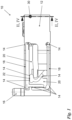
- FIG 1 shows, purely for the sake of orientation, a side view of an exemplary weighing system 10 in which the present invention is implemented.
- the weighing system 10 includes a base 12, which is to be understood as its fixed reference point.
- a load holder 16 which typically carries a weighing pan within a complete gravimetric measuring device, is articulated by means of links 18 via thin joints 14. Deflections of the load holder 16 are converted into one in by means of a multi-stage lever 20 Figure 1 not shown, in the functional gravimetric measuring device located inside the base 12. Individual sections of the lever 20 are connected to one another via further thin joints 14 and a coupling member 22.
- a free end region of the lever 20 is located in the area of the section line II, IV - II, IV and is in the Figures 2 to 5 shown in greater detail.
- the Figures 2 and 4 show the weighing system 10 in a sectional view along the section line II, IV - II, IV in two different positions, namely in an operating position ( Figure 2 ) and a rest position ( Figure 4 ).
- the Figures 3 and 5 each show enlarged representations corresponding to the magnification circles III in Figure 2 or V in Figure 4 .
- the Figures 2 to 5 should be discussed together below, as far as possible.
- the base 12 forms a lever channel 24 which extends between two walls 26, 28.
- the ones in the Figures 2 and 4 Wall 26 shown on the left will hereinafter simply be referred to as “wall” 26, whereas the one in the Figures 2 and 4 Wall 28 shown on the right should be addressed as the “opposite wall” 28.
- Both walls 26, 28 are penetrated by a through hole 30, which fulfills the function of a storage channel 32 in the interior of the wall 26 and, in the embodiment shown, fulfills no function within the opposite wall 28 and is only due to practical considerations of the manufacturing process.
- the lever 20 also has an opening 34, the cross section of which (at its narrowest point) is smaller than the cross section of the opening 32 in the wall 26, which serves as a storage channel.
- the lever opening 34 is provided with a blade-like taper, which defines its cross section (relevant to the invention) and ensures increased precision.
- the lever opening 34 could also be designed with a uniform cross section.
- a fixing bolt 36 is mounted in an axially displaceable manner in the wall opening 32.
- the fixing bolt 36 has a distal end section 38 with a smaller cross section and a main section 40 with a larger cross section.
- the main section 40 is divided into a distal subsection 40a and a proximal subsection 40b.
- the cross section of the distal end section 38 is smaller than the cross section of the lever opening 34; the cross section of the distal subsection 40a of the main section 40 corresponds to the cross section of the lever opening 34; and the cross section of the proximal subsection 40b of the main section 40 corresponds to the cross section of the wall opening 32.
- the fixing bolt 36 is mounted in the wall opening 32 so that it cannot tilt and is axially displaceable.
- the fixing bolt 36 In the in the Figures 2 and 3 In the operating position shown, the fixing bolt 36 is positioned so that its distal end section 38 passes through the narrowest point of the lever opening 34 at a complete distance.
- the lever 20 can therefore be pivoted to a limited extent relative to the base 12. This is completely sufficient, especially for scales that work according to the EMF principle, where only infinitesimal lever deflections occur during proper operation. However, if handled improperly, for example if a load is placed too hard on the weighing pan of the gravimetric measuring device, larger deflections can occur, which, however, are stopped in the operating position shown by the inner wall of the lever opening 34 striking the distal end section 38 of the fixing bolt 36 become. In this way, overloading of the sensitive thin joints 14 is prevented.
- the fixing bolt 36 can be advanced axially so that it is in the Figures 4 and 5 occupies the position shown.
- the main section 40 in particular its distal subsection 40a, passes through the lever opening 34 in a form-fitting manner. This prevents any deflection of the lever 20.
- the embodiment shown additionally has a locking screw 42 which opens into the bearing channel 32 and is designed as a simple clamping screw in the embodiment shown, with which the fixing bolt 36 can be clamped.
Landscapes
- Physics & Mathematics (AREA)
- Engineering & Computer Science (AREA)
- Chemical & Material Sciences (AREA)
- Manufacturing & Machinery (AREA)
- Materials Engineering (AREA)
- Mechanical Engineering (AREA)
- Electromagnetism (AREA)
- General Physics & Mathematics (AREA)
- Optics & Photonics (AREA)
- Weight Measurement For Supplying Or Discharging Of Specified Amounts Of Material (AREA)
- A Measuring Device Byusing Mechanical Method (AREA)
Description
Die Erfindung betrifft ein Verfahren zum Herstellen eines Wägesystems, im Rahmen dessen
- zunächst ein Rohling mit
- + einer Basis, die wenigstens eine Wand aufweist, und
- + einem über Dünnstellengelenke an der Basis angelenkten und über Materialbrücken an der Basis festgelegten Hebel, der einen der Wand benachbarten Hebelbereich aufweist,
- modelliert wird,
- wobei die Wand und der ihr benachbarte Hebelbereich mit je einem Durchbruch, die miteinander fluchten, versehen werden, und
- sodann die Materialbrücken aufgetrennt werden.
- First a blank
- + a base that has at least one wall, and
- + a lever that is articulated to the base via thin joints and fixed to the base via material bridges and has a lever area adjacent to the wall,
- is modeled,
- wherein the wall and the lever area adjacent to it are each provided with a breakthrough that is aligned with one another, and
- then the material bridges are separated.
Eine gattungsgemäße gravimetrische Messvorrichtung ist bekannt aus der
Gravimetrische Messvorrichtungen, insbesondere elektronische gravimetrische Messvorrichtungen, insbesondere solche, die nach dem Prinzip der elektromagnetischen Kompensation arbeiten (sog. EMK-Waagen) sind dem Fachmann allgemein bekannt. Sie umfassen regelmäßig ein sog. Wägesystem, d.h. eine komplizierte Anordnung von gefalteten Hebeln, Lenkern und Gelenken, die eine Lastaufnahme der Messvorrichtung unter Realisierung einer Weg- bzw. Kraftübersetzung mit dem eigentlichen Wägesensor, beispielsweise einem Spule-Magnet-System, verbindet. Ein solches Wägesystem umfasst regelmäßig eine Basis, die als fester Bezugspunkt dient und innerhalb der Messvorrichtung typischerweise fest mit deren Gehäuse verbunden ist und den festen Teil der Sensorik, insbesondere des Spule-Magnet-Systems, trägt. Hebel und Lenker sind relativ zu dieser Basis bewegbar, insbesondere über Gelenke an der Basis angelenkt. Bei modernen Präzisionswaagen sind sog. monolithische Wägesysteme weit verbreitet. Sie zeichnen sich dadurch aus, dass sämtliche oder zumindest nahezu sämtliche Bestandteile des Wägesystems einstückig miteinander verbunden sind, insbesondere aus einem zusammenhängenden Materialblock, typischerweise Aluminium, herausmodelliert sind. Ein solches monolithisches Wägesystem ist beispielsweise aus der
Beim Herstellen eines solchen Wägesystems nimmt der Rohling im Laufe des Verfahrens eine immer filigranere Struktur an. Gleichwohl bleiben die auf ihn und seine Bestandteile wirkenden, durch die Bearbeitung selbst wie auch durch seine Handhabung wirkenden Kräfte, insbesondere Beschleunigungs- und Spannungskräfte, im Wesentlichen gleich. Sie sind regelmäßig deutlich größer als die bei Betrieb einer fertigen Messvorrichtung auf deren Wägesystem wirkenden Kräfte. Insbesondere in einer späten Phase des Herstellungsverfahrens besteht daher die Gefahr einer Beschädigung der sehr empfindlichen, typischerweise als Dünnstellengelenke ausgebildeten Gelenke, wenn Hebel und/oder Lenker durch besagte Kräfte zu übermäßigen Auslenkungen angeregt werden. Um dies zu verhindern, ist es üblich, zumindest den Haupthebel des Systems über Materialbrücken an der Basis festzulegen bzw. festgelegt zu lassen und diese Materialbrücken erst als finalen Bearbeitungsschritt aufzutrennen. Auf diese Weise bleiben Relativbewegungen von Hebeln, Lenkern und Gelenken relativ zur Basis bis zu besagtem finalen Bearbeitungsschritt unterbunden. Zusätzlich wird insbesondere bei EMK-Waagen der noch festgelegte Hebel als Referenz genutzt, um die (in der Regel optische) Abtast-Sensorik für die Hebellage, die zur Regelung des Messstroms benötigt wird, zu justieren.When producing such a weighing system, the blank takes on an increasingly delicate structure as the process progresses. Nevertheless, the forces acting on it and its components, through the processing itself and through its handling, in particular acceleration and tension forces, remain essentially the same. They are regularly significantly larger than the forces acting on the weighing system when operating a finished measuring device. Particularly in a late phase of the manufacturing process, there is therefore a risk of damage to the very sensitive joints, which are typically designed as thin-point joints, if levers and/or handlebars are stimulated to excessive deflections by said forces. To prevent this, it is customary to at least use the main lever of the system to be fixed or left fixed via material bridges at the base and to separate these material bridges only as a final processing step. In this way, relative movements of levers, links and joints relative to the base are prevented until the final processing step. In addition, especially with EMF balances, the lever that is still fixed is used as a reference to adjust the (usually optical) scanning sensor system for the lever position that is required to regulate the measuring current.
Es hat sich allerdings gezeigt, dass gerade das Auftrennen der Materialbrücken, das häufig als ein Abkneifen vollzogen wird, zu einer erheblichen Hebelauslenkung führen kann, sodass der Rohling gerade im finalen Herstellungsstadium des Wägesystems besonders beschädigungs- und damit ausschussgefährdet ist.However, it has been shown that the separation of the material bridges, which is often carried out as a pinching operation, can lead to a significant deflection of the lever, so that the blank is particularly at risk of damage and therefore rejection, especially in the final manufacturing stage of the weighing system.
Aus der eingangs bereits genannten
Aus der
Es ist die Aufgabe der vorliegenden Erfindung, ein gattungsgemäßes Herstellungsverfahren für ein Wägesystem derart weiterzubilden, dass auch während der finalen Herstellungsphase eine Beschädigung der Gelenke verhindert wird.It is the object of the present invention to develop a generic manufacturing method for a weighing system in such a way that damage to the joints is prevented even during the final manufacturing phase.
Diese Aufgabe wird in Verbindung mit den Merkmalen des Oberbegriffs von Anspruch 1 dadurch gelöst, dass vor dem Auftrennen der Materialbrücken ein Fixierbolzen derart in die Durchbrüche geschoben wird, dass er während des Auftrennens der Materialbrücken formschlüssig in die Durchbrüche eingreift.This object is achieved in conjunction with the features of the preamble of claim 1 in that before the material bridges are separated, a fixing bolt is pushed into the openings in such a way that it engages in a form-fitting manner in the openings during the separation of the material bridges.
Bevorzugte Ausführungsformen der Erfindung sind Gegenstand der abhängigen Ansprüche.Preferred embodiments of the invention are the subject of the dependent claims.
Der Kern der Erfindung besteht in der Übertragung des aus dem Kontext einer Transportsicherung für vollständige gravimetrische Messvorrichtungen bekannten Konzeptes der Hebelfixierung mittels Fixierbolzens auf das Herstellungsverfahren des Wägesystems. So haben die Erfinder erkannt, dass die für die Beschädigung einer Messvorrichtung während deren Transportes ursächlichen Kräfte trotz völlig anderer physikalischer Grundlagen durchaus ähnlich den für die Gelenkschädigung beim Durchkneifen der Materialbrücken im Rahmen des finalen Herstellungsschrittes eines Wägesystems ursächlichen Kräfte sind. Aufbauend auf diese Erkenntnis schlägt die vorliegende Erfindung nun die neuartige Verwendung eines dem bekannten Transportbolzen ähnlichen Fixierbolzens zur Fixierung des Hebels während des Herstellungsverfahrens des Wägesystems, insbesondere während des finalen Herstellungsschrittes, d.h. während der Auftrennung der Materialbrücken zwischen Hebel und Basis, vor.The core of the invention consists in transferring the concept of lever fixation by means of fixing bolts, known from the context of transport security for complete gravimetric measuring devices, to the manufacturing process of the weighing system. The inventors have recognized that, despite completely different physical principles, the forces that cause damage to a measuring device during its transport are quite similar to the forces that cause damage to joints when the material bridges are pinched during the final manufacturing step of a weighing system. Building on this finding, the present invention now proposes the novel use of a fixing bolt similar to the known transport bolt for fixing the lever during the manufacturing process of the weighing system, in particular during the final manufacturing step, i.e. during the separation of the material bridges between the lever and the base.
Bei einer bevorzugten Ausführungsform ist vorgesehen, dass der Fixierbolzen wenigstens zwei koaxiale Axialabschnitte, nämlich einen distalen Endabschnitt und einen sich proximal an diesen anschließenden Hauptabschnitt, aufweist, wobei der Querschnitt des Hauptabschnitts wenigstens bereichsweise dem Querschnitt des Hebel-Durchbruchs entspricht und größer als der Querschnitt des distalen Endabschnitts ist. Für die oben geschilderte, grundlegende Wirkung der Erfindung im Rahmen der Wägesystem-Herstellung hat diese spezielle Dimensionierung des Fixierbolzens keine Bedeutung. In diesem Zusammenhang würde auch ein einfacher, zylindrischer Stift die beschriebene Funktion als Fixierbolzen zur Fixierung des Hebels in eine Sicherungsstellung erfüllen können. Die besondere Bedeutung der genannten Dimensionierung offenbart sich erst im Kontext einer gattungsgemäßen gravimetrischen Messvorrichtung, die sich durch besagte Dimensionierung des Fixierbolzens auszeichnet. Eine solche Fixierbolzen-Dimensionierung erlaubt nämlich insbesondere zwei Axialstellungen des Fixierbolzens, nämlich eine Ruhestellung, in der der formschlüssig und axial verschiebbar in dem Wand-Durchbruch gelagerte Fixierbolzen derart vorgeschoben ist, dass sein Hauptabschnitt formschlüssig in den Hebeldurchbruch eingreift. Diese Ruhestellung kann auch als Transportstellung bezeichnet werden und entspricht der im Kontext des Herstellungsverfahrens beschriebenen Sicherungsstellung während des finalen Herstellungsschrittes. Sie zeichnet sich durch eine formschlüssige Festlegung des Hebels an der Basis mittels des Fixerbolzens aus. Eine zweite, durch besagte Dimensionierung des Fixierbolzens ermöglichte Arbeitsstellung zeichnet sich dadurch aus, dass der Fixierbolzen gegenüber der vorbeschriebenen Ruhestellung derart zurückgezogen ist, dass sein distaler Endabschnitt mit radialem Abstand in den Hebel-Durchbruch eingreift und sein Hauptabschnitt axial außerhalb des Hebel-Durchbruchs positioniert ist. Der Formschluss des Fixierbolzen-Hauptabschnitts mit dem Wand-Durchbruch bleibt auch in der Arbeitsstellung erhalten. Mit anderen Worten zeichnet sich die Arbeitsstellung dadurch aus, dass der Hebel zwar relativ zur Basis schwenkbar ist, seine Auslenkung jedoch von dem seinen Durchbruch durchsetzenden distalen Endabschnitt des Fixierbolzens beschränkt ist. Bei übermäßiger Auslenkung des Hebels, wie sie beispielsweise bei einem zu harten Aufsetzen einer Last auf die Lastaufnahme der gravimetrischen Messvorrichtung auftreten kann, schlägt der Hebel mit der Innenwandung seines Durchbruchs am diesen durchsetzenden distalen Endabschnitt des Fixierbolzens an. Eine weitergehende Auslenkung, die zu einer Beschädigung der Gelenke führen könnte, wird auf diese Weise zuverlässig vermieden.In a preferred embodiment, it is provided that the fixing bolt has at least two coaxial axial sections, namely a distal end section and a main section that adjoins it proximally, the cross section of the main section being at least partially the cross section of the lever opening corresponds and is larger than the cross section of the distal end section. This special dimensioning of the fixing bolt has no significance for the fundamental effect of the invention described above in the context of weighing system production. In this context, a simple, cylindrical pin would also be able to fulfill the described function as a fixing bolt for fixing the lever in a securing position. The special significance of the dimensioning mentioned is only revealed in the context of a generic gravimetric measuring device, which is characterized by the said dimensioning of the fixing bolt. Such a fixing bolt dimensioning allows in particular two axial positions of the fixing bolt, namely a rest position in which the fixing bolt, which is mounted in a form-fitting and axially displaceable manner in the wall opening, is advanced in such a way that its main section engages in a form-fitting manner in the lever opening. This rest position can also be referred to as the transport position and corresponds to the securing position described in the context of the manufacturing process during the final manufacturing step. It is characterized by a positive fixation of the lever on the base using the fixing bolt. A second working position made possible by said dimensioning of the fixing bolt is characterized in that the fixing bolt is retracted from the above-described rest position in such a way that its distal end section engages in the lever opening at a radial distance and its main section is positioned axially outside the lever opening . The positive connection between the fixing bolt main section and the wall opening is retained even in the working position. In other words, the working position is characterized by the fact that the lever can be pivoted relative to the base, but its deflection is limited by the distal end section of the fixing bolt which passes through its opening. In the event of excessive deflection of the lever, as can occur, for example, when a load is placed too hard on the load holder of the gravimetric measuring device, the lever strikes with the inner wall of its opening on the distal end section of the fixing bolt that passes through it. In this way, further deflection, which could lead to damage to the joints, is reliably avoided.
Einem derart dimensionierten Fixierbolzen kommt also eine vierfache Funktion zu: Erstens dient er der Ausschuss-Reduzierung im Rahmen der Wägesystem-Herstellung; zweitens dient er der Festlegung des Hebels als Referenz für die Justage der Abtastelektronik; drittens dient er (in grundsätzlich bekannter Weise) einer Transportsicherung der gravimetrischen Messvorrichtung; und viertens bildet er einen Sicherheitsanschlag für den Hebel während des Betriebs der gravimetrischen Messvorrichtung.A fixing bolt dimensioned in this way has a fourfold function: Firstly, it serves to reduce waste in the context of weighing system production; secondly, it serves to determine the lever as a reference for adjusting the scanning electronics; thirdly, it serves (in a fundamentally known manner) to secure the gravimetric measuring device for transport; and fourthly, it forms a safety stop for the lever during operation of the gravimetric measuring device.
Hieraus ergibt sich das erfindungsgemäße Betriebsverfahren für eine vorzugsweise erfindungsgemäß hergestellte, erfindungsgemäße gravimetrische Messvorrichtung, welches sich dadurch auszeichnet, dass der Fixierbolzen formschlüssig und axial verschiebbar in dem Wand-Durchbruch gelagert ist und bedarfsweise
- zur Überführung der Messvorrichtung in eine Ruhestellung derart vorgeschoben geschoben wird, dass sein Hauptabschnitt formschlüssig in den Hebel-Durchbruch eingreift
und - zur Überführung der Messvorrichtung in eine Arbeitsstellung derart zurückgezogen wird, dass sein distaler Endabschnitt mit radialem Abstand in den Hebel-Durchbruch eingreift und sein Hauptabschnitt axial außerhalb des Hebel-Durchbruchs positioniert wird.
- To transfer the measuring device to a rest position, it is pushed forward in such a way that its main section engages positively in the lever opening
and - To transfer the measuring device into a working position, it is retracted in such a way that its distal end section engages in the lever opening at a radial distance and its main section is positioned axially outside the lever opening.
Der Fachmann wird erkennen, dass der Begriff des Durchbruchs im vorliegenden Kontext weit zu verstehen ist und sowohl Durchgangsöffnungen wie auch Sacklöcher umfasst. Als Querschnitt ist der jeweils funktional relevante Querschnitt, d. h. in der Regel der jeweils kleinste lichte Querschnitt einer Öffnung und der Außenquerschnitt des jeweils konkret wechselwirkenden Axialabschnittes eines Körpers zu verstehen. Auch wird der Fachmann erkennen, dass der Begriff des Durchgreifens nicht zwingend einen vollständigen Durchgriff impliziert.The person skilled in the art will recognize that the term breakthrough is to be understood broadly in the present context and includes both through openings and blind holes. The cross-section is the functionally relevant cross-section, i.e. H. As a rule, this means the smallest clear cross section of an opening and the outer cross section of the specifically interacting axial section of a body. The expert will also recognize that the term crackdown does not necessarily imply a complete crackdown.
Das Modellieren des Rohlings im Rahmen des erfindungsgemäßen Wägesystem-Herstellungsverfahrens kann, wie grundsätzlich bekannt, durch subtraktive Bearbeitung eines monolithischen Materialblocks erfolgen. Insbesondere ist es möglich, das erfindungsgemäße Wägesystem auf grundsätzlich dieselbe Weise, nämlich durch Fräsen, Bohren und Schleifen eines Material-, insbesondere eines Aluminiumblocks, wie herkömmlich bekannt, zu schaffen. Alternativ kann das Modellieren des Rohlings wenigstens bereichsweise auch durch ein additives Verfahren erfolgen. In ihrer stärksten Ausprägung wird bei dieser Ausführungsform das gesamte Wägesystem additiv, beispielsweise durch 3D-Druck, aufgebaut. Kombinationen subtraktiver und additiver Verfahrensschritte sind im Kontext der vorliegenden Erfindung jedoch ebenfalls möglich.The modeling of the blank as part of the weighing system manufacturing method according to the invention can, as is generally known, be carried out by subtractive processing of a monolithic material block. In particular, it is possible to create the weighing system according to the invention in basically the same way, namely by milling, drilling and grinding a block of material, in particular an aluminum block, as is conventionally known. Alternatively, the modeling of the blank can also be carried out at least in some areas using an additive process. In its strongest form, in this embodiment the entire weighing system is additive, for example, built using 3D printing. However, combinations of subtractive and additive process steps are also possible in the context of the present invention.
Die Querschnitte des distalen Endbereichs und des Hauptschnitts des Fixierbolzens sind bevorzugt kreisrund. Insbesondere im Rahmen eines subtraktiven Herstellungsverfahrens des Wägesystems lassen sich solche Formen durch einfaches Bohren des Rohlings schaffen. Im Kontext eines additiven Modellierungsverfahrens für das Wägesystem sind auch komplexere Querschnittsformen denkbar, die dann zugleich eine Verdrehsicherung des Fixierbolzens realisieren können. In der Praxis hat sich jedoch die Wahl kreisrunder Querschnittsformen bewährt.The cross sections of the distal end region and the main section of the fixing bolt are preferably circular. Particularly in the context of a subtractive manufacturing process of the weighing system, such shapes can be created by simply drilling the blank. In the context of an additive modeling process for the weighing system, more complex cross-sectional shapes are also conceivable, which can then also provide anti-twist protection for the fixing bolt. In practice, however, the choice of circular cross-sectional shapes has proven successful.
Die oben beschriebene Grundform des erfindungsgemäßen Fixierbolzens mit einem dünneren distalen Endabschnitt und einem dickeren Hauptabschnitt kann in der Praxis komplexer ausgestaltet werden. So ist bei einer vorteilhaften Weiterbildung der Erfindung vorgesehen, dass der Hauptabschnitt des Fixierbolzens in zwei axiale Unterabschnitte, nämlich einen distalen und einen proximalen Unterabschnitt, unterteilt ist, wobei der Querschnitt des proximalen Unterabschnitts größer als der Querschnitt des distalen Unterabschnitts ist und dem Querschnitt des Wand-Durchbruchs entspricht. Ungeachtet dieser Ausgestaltung des Hauptabschnitts ist selbstverständlich der distale Endabschnitt mit einem nochmals kleineren Querschnitt versehen. Bei dieser Ausführungsform dient der proximale Unterabschnitt des Fixierbolzen-Hauptabschnitts im Wesentlichen dessen Lagerung im Wand-Durchbruch. Entsprechend stimmen deren Querschnitte auch überein. Der distale Unterabschnitt des Fixierbolzen-Hauptabschnitts dient der Funktion der Transportsicherung und ist derjenige Teil des Fixierbolzens, der zum Zwecke der Transportsicherung formschlüssig in den Hebeldurchbruch eingeschoben werden kann. Der sich distal anschließende, distale Endabschnitt hingegen dient der Funktion als Sicherheitsanschlag während des Betriebes und greift mit radialem Abstand in den Hebel-Durchbruch ein.The basic shape of the fixing bolt according to the invention described above with a thinner distal end section and a thicker main section can be designed to be more complex in practice. In an advantageous development of the invention, it is provided that the main section of the fixing bolt is divided into two axial subsections, namely a distal and a proximal subsection, the cross section of the proximal subsection being larger than the cross section of the distal subsection and the cross section of the wall breakthrough. Regardless of this design of the main section, the distal end section is of course provided with an even smaller cross section. In this embodiment, the proximal subsection of the fixing bolt main section essentially serves to support it in the wall opening. Accordingly, their cross sections also match. The distal subsection of the fixing bolt main section serves the function of transport security and is the part of the fixation bolt that can be inserted in a form-fitting manner into the lever opening for the purpose of transport security. The distal end section, on the other hand, serves the function of a safety stop during operation and engages with the lever opening at a radial distance.
Denkbar sind auch Varianten, bei denen sich der distale Endabschnitt bis zu einer gegenüberliegenden Wand und in eine in dieser befindliche Ausnehmung hinein erstreckt. Diese Ausnehmung und der distale Endabschnitt des Fixierbolzens sind dabei vorzugsweise so dimensioniert, dass letzterer formschlüssig in erstere einzugreifen vermag. Hierdurch wird eine zweiseitige Lagerung des Fixierbolzens realisiert, wodurch grundsätzlich eine größere Stabilität der Fixierbolzen-Positionierung als bei einseitiger Lagerung ermöglicht wird. Allerdings hat sich in der Praxis herausgestellt, dass insbesondere die Längendimension des Fixierbolzens typischerweise hinreichend klein ist, um auch bei einseitiger Lagerung eine vollkommen hinreichende Stabilität zu erzielen.Variants are also conceivable in which the distal end section extends to an opposite wall and into a recess located therein. This recess and the distal end section of the fixing bolt are preferably dimensioned so that the latter can engage in the former in a form-fitting manner. This ensures that the fixing bolt is mounted on two sides, which means In principle, greater stability of the fixing bolt positioning is enabled than with one-sided storage. However, in practice it has been found that the length dimension of the fixing bolt in particular is typically sufficiently small to achieve completely sufficient stability even when stored on one side.
Der Übergang zwischen dem distalen Endabschnitt und dem Hauptabschnitt des Fixierbolzens ist bevorzugt mit einer Anfasung versehen. Bei der Überführung des Fixierbolzens bzw. der gravimetrischen Wägevorrichtung von ihrer Betriebs- in ihre Ruhe- bzw. Transportstellung bewirkt diese Anfasung bei einem leicht aus seiner Gleichgewichtsstellung ausgelenkten Hebel dessen automatische Überführung in die Gleichgewichtsstellung. Insbesondere wird eine übermäßige Beaufschlagung des Hebels mit einer Lateralkraft vermieden.The transition between the distal end section and the main section of the fixing bolt is preferably provided with a chamfer. When the fixing bolt or the gravimetric weighing device is transferred from its operating position to its rest or transport position, this chamfering causes the lever to be automatically transferred to the equilibrium position when the lever is slightly deflected from its equilibrium position. In particular, excessive loading of the lever with a lateral force is avoided.
Die Axialverschiebung des Fixierbolzens kann beispielsweise manuell erfolgen. In diesem Fall ist es besonders günstig, wenn der Fixierbolzen, wie allgemein bevorzugt vorgesehen, mittels einer Feststellschraube, die z.B. als Klemmschraube oder als kraft- und formschlüssig wirkende Feststellschraube ausgebildet sein kann, in unterschiedlichen Axialstellungen feststellbar ist. Eine versehentliche Verschiebung wird damit weitestgehend ausgeschlossen.The axial displacement of the fixing bolt can be done manually, for example. In this case, it is particularly advantageous if the fixing bolt, as is generally preferred, can be locked in different axial positions by means of a locking screw, which can be designed, for example, as a clamping screw or as a non-positive and positive locking screw. This largely eliminates the possibility of accidental displacement.
Allerdings kann alternativ zur manuellen Fixierbolzen-Verschiebung auch vorgesehen sein, dass die gravimetrische Messvorrichtung weiter einen motorischen Antrieb umfasst, mittels dessen der Fixierbolzen axial verschiebbar ist. Die Motorsteuerung kann mit der allgemeinen Waagensteuerung gekoppelt sein. Damit wird die Fixierbolzen-Verschiebung jeder Fehlbedienung vollständig entzogen. Da der Motor in der Regel auch eine Festlegung des Fixierbolzens in der jeweiligen Zielstellung bewirkt, kann bei dieser Ausführungsform meist auch ohne weiteres auf die oben erwähnte Feststellschraube verzichtet werden.However, as an alternative to manual fixing bolt displacement, it can also be provided that the gravimetric measuring device further comprises a motor drive, by means of which the fixing bolt is axially displaceable. The motor control can be linked to the general scale control. This means that the fixing bolt displacement is completely prevented from any incorrect operation. Since the motor usually also fixes the fixing bolt in the respective target position, the above-mentioned locking screw can usually be dispensed with in this embodiment.
Weitere Einzelheiten und Vorteile der Erfindung ergeben sich aus der nachfolgenden speziellen Beschreibung und den Zeichnungen.Further details and advantages of the invention emerge from the following specific description and the drawings.
Es zeigen:
- Figur 1:
- eine Seitenansicht eines beispielhaften Wägesystems,
- Figur 2:
- eine Schnittdarstellung durch das Wägesystem von
Figur 1 entlang der Schnittlinie II, IV - II, IV, - Figur 3:
- eine Vergrößerung des Ausschnitts III von
Figur 2 , - Figur 4:
- eine Schnittdarstellung durch das Wägesystem von
Figur 1 entlang der Schnittlinie II, IV - II, IV sowie - Figur 5:
- eine Vergrößerung des Ausschnitts
V von Figur 4 .
- Figure 1:
- a side view of an exemplary weighing system,
- Figure 2:
- a sectional view through the weighing system
Figure 1 along the section line II, IV - II, IV, - Figure 3:
- an enlargement of section III of
Figure 2 , - Figure 4:
- a sectional view through the weighing system
Figure 1 along the section line II, IV - II, IV as well - Figure 5:
- an enlargement of section V of
Figure 4 .
Gleiche Bezugszeichen in den Figuren deuten auf gleiche oder analoge Elemente hin.The same reference numbers in the figures indicate the same or analogous elements.
Ein freier Endbereich des Hebels 20 befindet sich im Bereich der Schnittlinie II, IV - II, IV und ist in den
Die
Bei der dargestellten Ausführungsform bildet die Basis 12 einen Hebelkanal 24, der sich zwischen zwei Wänden 26, 28 erstreckt. Die in den
Auch der Hebel 20 weist einen Durchbruch 34 auf, dessen Querschnitt (an seiner engsten Stelle) kleiner ist als der Querschnitt des als Lagerkanal dienenden Durchbruchs 32 der Wand 26. Bei der dargestellten Ausführungsform ist der Hebel-Durchbruch 34 mit einer schneidenartigen Verjüngung versehen, die seinen (erfindungsrelevanten) Querschnitt definiert und für eine erhöhte Präzision sorgt. Grundsätzlich könnte der Hebel-Durchbruch 34 auch mit einem gleichmäßigen Querschnitt ausgestaltet sein.The
Im Wand-Durchbruch 32 ist ein Fixierbolzen 36 axial verschieblich gelagert. Der Fixierbolzen 36 weist einen distalen Endabschnitt 38 geringeren Querschnitts und einen Hauptabschnitt 40 größeren Querschnitts auf. Bei der dargestellten Ausführungsform ist der Hauptabschnitt 40 in einen distalen Unterabschnitt 40a und einen proximalen Unterabschnitt 40b unterteilt. Der Querschnitt des distalen Endabschnitts 38 ist kleiner als der Querschnitt des Hebel-Durchbruchs 34; der Querschnitt des distalen Unterabschnitts 40a des Hauptabschnitts 40 entspricht dem Querschnitt des Hebel-Durchbruchs 34; und der Querschnitt des proximalen Unterabschnitts 40b des Hauptabschnitts 40 entspricht dem Querschnitt des Wand-Durchbruchs 32. Auf diese Weise ist der Fixierbolzen 36 verkippsicher und axial verschiebbar im Wand-Durchbruch 32 gelagert.A fixing
In der in den
Nach Betrieb und insbesondere zur Vorbereitung für einen Transport der gravimetrischen Messvorrichtung kann der Fixierbolzen 36 axial vorgeschoben werden, sodass er die in den
Um eine unbeabsichtigte Axialverschiebung des Fixierbolzens 36 zu verhindern, weist die dargestellte Ausführungsform zusätzlich eine in den Lagerkanal 32 mündende, bei der gezeigten Ausführungsform als einfache Klemmschraube ausgebildete Feststellschraube 42 auf, mit der der Fixierbolzen 36 geklemmt werden kann.In order to prevent unintentional axial displacement of the fixing
Natürlich stellen die in der speziellen Beschreibung diskutierten und in den Figuren gezeigten Ausführungsformen nur illustrative Ausführungsbeispiele der vorliegenden Erfindung dar. Dem Fachmann ist im Lichte der hiesigen Offenbarung ein breites Spektrum von Variationsmöglichkeiten an die Hand gegeben. Insbesondere ist es denkbar, den distalen Endabschnitt 38 des Fixierbolzens 36 bis zur gegenüberliegenden Wand 28 hin zu verlängern und dort in einer entsprechend dimensionierten Ausnehmung axialverschieblich zu lagern.Of course, the embodiments discussed in the special description and shown in the figures only represent illustrative embodiments of the present invention. In the light of the disclosure here, the person skilled in the art is provided with a wide range of possible variations. In particular, it is conceivable to extend the
- 1010
- Wägesystemweighing system
- 1212
- BasisBase
- 1414
- DünnstellengelenkThin spot joint
- 1616
- LastaufnahmeLoad carrying
- 1818
- LenkerHandlebars
- 2020
- Hebellever
- 2222
- Koppelgliedcoupling link
- 2424
- Hebelkanallever channel
- 2626
- WandWall
- 2828
- gegenüberliegende Wandopposite wall
- 3030
- Bohrungdrilling
- 3232
- Wand-Durchbruch/LagerkanalWall breakthrough/storage channel
- 3434
- Hebel-DurchbruchLeverage breakthrough
- 3636
- FixierbolzenFixing bolts
- 3838
- distaler Endabschnitt von 36distal end section of 36
- 4040
- Hauptabschnitt von 36Main section of 36
- 40a40a
- distaler Unterabschnitt von 40distal subsection of 40
- 40b40b
- proximaler Unterabschnitt von 40proximal subsection of 40
- 4242
- FeststellschraubeLocking screw
Claims (4)
- Method for producing a weighing system (10), in the context of which:- first a blank is modeled, said blank comprising+ a base (12) having at least one wall (26), and+ a lever (20) which is hinged to the base (12) via thin-section joints (14) and is secured to the base (12) via material bridges, said lever having a lever region adjacent to the wall (26),wherein the wall (26) and the lever region adjacent thereto are each provided with an aperture (32, 34), said apertures being aligned with each other, and- then the material bridges are cut open,characterized
in that, before the material bridges are cut open, a fixing bolt (36) is pushed into the apertures (32, 34) such that it engages in the apertures (32, 34) with a form fit while the material bridges are being cut open. - Method according to claim 1,
characterized
in that the fixing bolt (36) comprises at least two coaxial axial portions (38, 40), namely a distal end portion (38) and a main portion (40) proximally adjoining the latter, wherein the cross-section of the main portion (40) corresponds at least in part to the cross-section of the lever aperture (34) and is larger than the cross-section of the distal end portion (38). - Method according to any one of the preceding claims,
in that the modeling of the blank takes place by subtractive machining of a monolithic block of material. - Method according to any one of the preceding claims,
characterized
in that the modeling of the blank takes place at least in part by an additive process.
Applications Claiming Priority (2)
| Application Number | Priority Date | Filing Date | Title |
|---|---|---|---|
| DE102020102606.4A DE102020102606B4 (en) | 2020-02-03 | 2020-02-03 | Method of manufacturing a weighing system |
| PCT/EP2021/050121 WO2021156010A1 (en) | 2020-02-03 | 2021-01-06 | Method for producing a weighing system, gravimetric measuring device and method for operating said gravimetric measuring device |
Publications (2)
| Publication Number | Publication Date |
|---|---|
| EP4100703A1 EP4100703A1 (en) | 2022-12-14 |
| EP4100703B1 true EP4100703B1 (en) | 2023-10-11 |
Family
ID=74183140
Family Applications (1)
| Application Number | Title | Priority Date | Filing Date |
|---|---|---|---|
| EP21700260.9A Active EP4100703B1 (en) | 2020-02-03 | 2021-01-06 | Method for producing a weighing system |
Country Status (5)
| Country | Link |
|---|---|
| US (1) | US12326357B2 (en) |
| EP (1) | EP4100703B1 (en) |
| CN (1) | CN115038942B (en) |
| DE (1) | DE102020102606B4 (en) |
| WO (1) | WO2021156010A1 (en) |
Families Citing this family (1)
| Publication number | Priority date | Publication date | Assignee | Title |
|---|---|---|---|---|
| DE102019113001A1 (en) * | 2019-05-16 | 2020-11-19 | Wipotec Gmbh | Monolithic weighing block |
Family Cites Families (10)
| Publication number | Priority date | Publication date | Assignee | Title |
|---|---|---|---|---|
| CH656711A5 (en) * | 1982-07-16 | 1986-07-15 | Mettler Instrumente Ag | WEIGHING CELL. |
| US4734671A (en) | 1986-10-22 | 1988-03-29 | Solartron Electronics, Inc. | Strain gage beam having integral overload protection |
| DE29708886U1 (en) | 1996-07-19 | 1997-07-17 | Mettler-Toledo Gmbh, Greifensee | Shock protection for a force measuring device |
| DE19845023A1 (en) * | 1998-09-30 | 2000-04-06 | Mettler Toledo Gmbh | Force measuring device, in particular load cell |
| DE202007005665U1 (en) | 2007-04-19 | 2007-07-12 | Sartorius Ag | Scale with transport lock for the weighing system |
| DE102013103791B4 (en) | 2013-04-16 | 2015-07-09 | Sartorius Lab Instruments Gmbh & Co. Kg | Monolithic weighing system |
| EP3153830B1 (en) * | 2015-10-06 | 2018-06-20 | Mettler-Toledo GmbH | Load receiver with locking means |
| JP6509765B2 (en) | 2016-03-08 | 2019-05-08 | アンリツインフィビス株式会社 | Weight measuring device |
| DE102018131125A1 (en) | 2018-12-06 | 2020-06-10 | Minebea Intec Aachen GmbH & Co. KG | Locking device for a weighing sensor |
| DE102019113001A1 (en) * | 2019-05-16 | 2020-11-19 | Wipotec Gmbh | Monolithic weighing block |
-
2020
- 2020-02-03 DE DE102020102606.4A patent/DE102020102606B4/en active Active
-
2021
- 2021-01-06 CN CN202180012325.XA patent/CN115038942B/en active Active
- 2021-01-06 EP EP21700260.9A patent/EP4100703B1/en active Active
- 2021-01-06 WO PCT/EP2021/050121 patent/WO2021156010A1/en not_active Ceased
-
2022
- 2022-08-02 US US17/879,373 patent/US12326357B2/en active Active
Also Published As
| Publication number | Publication date |
|---|---|
| CN115038942B (en) | 2024-07-09 |
| DE102020102606B4 (en) | 2022-02-24 |
| EP4100703A1 (en) | 2022-12-14 |
| DE102020102606A1 (en) | 2021-08-05 |
| CN115038942A (en) | 2022-09-09 |
| WO2021156010A1 (en) | 2021-08-12 |
| US12326357B2 (en) | 2025-06-10 |
| US20220373383A1 (en) | 2022-11-24 |
Similar Documents
| Publication | Publication Date | Title |
|---|---|---|
| EP1569845B1 (en) | Aircraft door arrangement | |
| EP2058084A1 (en) | Stationary support | |
| WO2014091022A1 (en) | Joining and guiding device | |
| DE102011001924B4 (en) | Transfer device for a press or press line with axle drive and interchangeable base carrier | |
| EP1983147A2 (en) | Construction device, leads and method for mounting leads on construction device | |
| EP2701860B1 (en) | Tool holder for press brake | |
| EP1547916B1 (en) | Sliding door for an aircraft | |
| EP4100703B1 (en) | Method for producing a weighing system | |
| EP0103912A1 (en) | Pliers device | |
| EP1983149B2 (en) | Mast | |
| DE4413444A1 (en) | Loading ramp for vehicle | |
| DE3322551C2 (en) | Intermediate piece for switching off the lateral mobility of the lower links of an agricultural tractor | |
| DE102015104498B4 (en) | Folding mechanism for a conveyor | |
| DE2953352C2 (en) | ||
| DE3712520C2 (en) | ||
| DE3242659C2 (en) | ||
| EP4009013B1 (en) | Structural body of a scale sensor | |
| EP2154488A2 (en) | Flap sensor unit | |
| DE10305399A1 (en) | Robotic arm mechanism | |
| DE10229016B4 (en) | pivot bearing | |
| WO2016062840A1 (en) | Door system for an elevator installation | |
| EP0281109B1 (en) | Writing device including a writing head arrangement and a platen | |
| EP4574291A1 (en) | Bending machine, in particular press brake | |
| DE19525387C2 (en) | Device for releasably attaching a tool to an arm of a construction machine | |
| DE2449078C3 (en) | Gripper for an industrial machine |
Legal Events
| Date | Code | Title | Description |
|---|---|---|---|
| STAA | Information on the status of an ep patent application or granted ep patent |
Free format text: STATUS: UNKNOWN |
|
| STAA | Information on the status of an ep patent application or granted ep patent |
Free format text: STATUS: THE INTERNATIONAL PUBLICATION HAS BEEN MADE |
|
| PUAI | Public reference made under article 153(3) epc to a published international application that has entered the european phase |
Free format text: ORIGINAL CODE: 0009012 |
|
| STAA | Information on the status of an ep patent application or granted ep patent |
Free format text: STATUS: REQUEST FOR EXAMINATION WAS MADE |
|
| 17P | Request for examination filed |
Effective date: 20220818 |
|
| AK | Designated contracting states |
Kind code of ref document: A1 Designated state(s): AL AT BE BG CH CY CZ DE DK EE ES FI FR GB GR HR HU IE IS IT LI LT LU LV MC MK MT NL NO PL PT RO RS SE SI SK SM TR |
|
| DAV | Request for validation of the european patent (deleted) | ||
| DAX | Request for extension of the european patent (deleted) | ||
| REG | Reference to a national code |
Ref country code: DE Ref legal event code: R079 Free format text: PREVIOUS MAIN CLASS: G01G0007020000 Ipc: G01G0021240000 Ref country code: DE Ref legal event code: R079 Ref document number: 502021001699 Country of ref document: DE Free format text: PREVIOUS MAIN CLASS: G01G0007020000 Ipc: G01G0021240000 |
|
| GRAP | Despatch of communication of intention to grant a patent |
Free format text: ORIGINAL CODE: EPIDOSNIGR1 |
|
| STAA | Information on the status of an ep patent application or granted ep patent |
Free format text: STATUS: GRANT OF PATENT IS INTENDED |
|
| GRAS | Grant fee paid |
Free format text: ORIGINAL CODE: EPIDOSNIGR3 |
|
| RIC1 | Information provided on ipc code assigned before grant |
Ipc: G01G 21/24 20060101AFI20230727BHEP |
|
| INTG | Intention to grant announced |
Effective date: 20230809 |
|
| GRAA | (expected) grant |
Free format text: ORIGINAL CODE: 0009210 |
|
| STAA | Information on the status of an ep patent application or granted ep patent |
Free format text: STATUS: THE PATENT HAS BEEN GRANTED |
|
| P01 | Opt-out of the competence of the unified patent court (upc) registered |
Effective date: 20230828 |
|
| AK | Designated contracting states |
Kind code of ref document: B1 Designated state(s): AL AT BE BG CH CY CZ DE DK EE ES FI FR GB GR HR HU IE IS IT LI LT LU LV MC MK MT NL NO PL PT RO RS SE SI SK SM TR |
|
| REG | Reference to a national code |
Ref country code: GB Ref legal event code: FG4D Free format text: NOT ENGLISH |
|
| REG | Reference to a national code |
Ref country code: CH Ref legal event code: EP |
|
| REG | Reference to a national code |
Ref country code: DE Ref legal event code: R096 Ref document number: 502021001699 Country of ref document: DE |
|
| REG | Reference to a national code |
Ref country code: IE Ref legal event code: FG4D Free format text: LANGUAGE OF EP DOCUMENT: GERMAN |
|
| REG | Reference to a national code |
Ref country code: LT Ref legal event code: MG9D |
|
| REG | Reference to a national code |
Ref country code: NL Ref legal event code: MP Effective date: 20231011 |
|
| PG25 | Lapsed in a contracting state [announced via postgrant information from national office to epo] |
Ref country code: NL Free format text: LAPSE BECAUSE OF FAILURE TO SUBMIT A TRANSLATION OF THE DESCRIPTION OR TO PAY THE FEE WITHIN THE PRESCRIBED TIME-LIMIT Effective date: 20231011 |
|
| PG25 | Lapsed in a contracting state [announced via postgrant information from national office to epo] |
Ref country code: GR Free format text: LAPSE BECAUSE OF FAILURE TO SUBMIT A TRANSLATION OF THE DESCRIPTION OR TO PAY THE FEE WITHIN THE PRESCRIBED TIME-LIMIT Effective date: 20240112 |
|
| PG25 | Lapsed in a contracting state [announced via postgrant information from national office to epo] |
Ref country code: IS Free format text: LAPSE BECAUSE OF FAILURE TO SUBMIT A TRANSLATION OF THE DESCRIPTION OR TO PAY THE FEE WITHIN THE PRESCRIBED TIME-LIMIT Effective date: 20240211 |
|
| PG25 | Lapsed in a contracting state [announced via postgrant information from national office to epo] |
Ref country code: LT Free format text: LAPSE BECAUSE OF FAILURE TO SUBMIT A TRANSLATION OF THE DESCRIPTION OR TO PAY THE FEE WITHIN THE PRESCRIBED TIME-LIMIT Effective date: 20231011 |
|
| PG25 | Lapsed in a contracting state [announced via postgrant information from national office to epo] |
Ref country code: ES Free format text: LAPSE BECAUSE OF FAILURE TO SUBMIT A TRANSLATION OF THE DESCRIPTION OR TO PAY THE FEE WITHIN THE PRESCRIBED TIME-LIMIT Effective date: 20231011 |
|
| PG25 | Lapsed in a contracting state [announced via postgrant information from national office to epo] |
Ref country code: LT Free format text: LAPSE BECAUSE OF FAILURE TO SUBMIT A TRANSLATION OF THE DESCRIPTION OR TO PAY THE FEE WITHIN THE PRESCRIBED TIME-LIMIT Effective date: 20231011 Ref country code: IS Free format text: LAPSE BECAUSE OF FAILURE TO SUBMIT A TRANSLATION OF THE DESCRIPTION OR TO PAY THE FEE WITHIN THE PRESCRIBED TIME-LIMIT Effective date: 20240211 Ref country code: GR Free format text: LAPSE BECAUSE OF FAILURE TO SUBMIT A TRANSLATION OF THE DESCRIPTION OR TO PAY THE FEE WITHIN THE PRESCRIBED TIME-LIMIT Effective date: 20240112 Ref country code: ES Free format text: LAPSE BECAUSE OF FAILURE TO SUBMIT A TRANSLATION OF THE DESCRIPTION OR TO PAY THE FEE WITHIN THE PRESCRIBED TIME-LIMIT Effective date: 20231011 Ref country code: BG Free format text: LAPSE BECAUSE OF FAILURE TO SUBMIT A TRANSLATION OF THE DESCRIPTION OR TO PAY THE FEE WITHIN THE PRESCRIBED TIME-LIMIT Effective date: 20240111 Ref country code: PT Free format text: LAPSE BECAUSE OF FAILURE TO SUBMIT A TRANSLATION OF THE DESCRIPTION OR TO PAY THE FEE WITHIN THE PRESCRIBED TIME-LIMIT Effective date: 20240212 |
|
| PG25 | Lapsed in a contracting state [announced via postgrant information from national office to epo] |
Ref country code: SE Free format text: LAPSE BECAUSE OF FAILURE TO SUBMIT A TRANSLATION OF THE DESCRIPTION OR TO PAY THE FEE WITHIN THE PRESCRIBED TIME-LIMIT Effective date: 20231011 Ref country code: RS Free format text: LAPSE BECAUSE OF FAILURE TO SUBMIT A TRANSLATION OF THE DESCRIPTION OR TO PAY THE FEE WITHIN THE PRESCRIBED TIME-LIMIT Effective date: 20231011 Ref country code: PL Free format text: LAPSE BECAUSE OF FAILURE TO SUBMIT A TRANSLATION OF THE DESCRIPTION OR TO PAY THE FEE WITHIN THE PRESCRIBED TIME-LIMIT Effective date: 20231011 Ref country code: NO Free format text: LAPSE BECAUSE OF FAILURE TO SUBMIT A TRANSLATION OF THE DESCRIPTION OR TO PAY THE FEE WITHIN THE PRESCRIBED TIME-LIMIT Effective date: 20240111 Ref country code: LV Free format text: LAPSE BECAUSE OF FAILURE TO SUBMIT A TRANSLATION OF THE DESCRIPTION OR TO PAY THE FEE WITHIN THE PRESCRIBED TIME-LIMIT Effective date: 20231011 Ref country code: HR Free format text: LAPSE BECAUSE OF FAILURE TO SUBMIT A TRANSLATION OF THE DESCRIPTION OR TO PAY THE FEE WITHIN THE PRESCRIBED TIME-LIMIT Effective date: 20231011 |
|
| PG25 | Lapsed in a contracting state [announced via postgrant information from national office to epo] |
Ref country code: DK Free format text: LAPSE BECAUSE OF FAILURE TO SUBMIT A TRANSLATION OF THE DESCRIPTION OR TO PAY THE FEE WITHIN THE PRESCRIBED TIME-LIMIT Effective date: 20231011 |
|
| REG | Reference to a national code |
Ref country code: DE Ref legal event code: R097 Ref document number: 502021001699 Country of ref document: DE |
|
| PG25 | Lapsed in a contracting state [announced via postgrant information from national office to epo] |
Ref country code: CZ Free format text: LAPSE BECAUSE OF FAILURE TO SUBMIT A TRANSLATION OF THE DESCRIPTION OR TO PAY THE FEE WITHIN THE PRESCRIBED TIME-LIMIT Effective date: 20231011 |
|
| PG25 | Lapsed in a contracting state [announced via postgrant information from national office to epo] |
Ref country code: SK Free format text: LAPSE BECAUSE OF FAILURE TO SUBMIT A TRANSLATION OF THE DESCRIPTION OR TO PAY THE FEE WITHIN THE PRESCRIBED TIME-LIMIT Effective date: 20231011 |
|
| PG25 | Lapsed in a contracting state [announced via postgrant information from national office to epo] |
Ref country code: SM Free format text: LAPSE BECAUSE OF FAILURE TO SUBMIT A TRANSLATION OF THE DESCRIPTION OR TO PAY THE FEE WITHIN THE PRESCRIBED TIME-LIMIT Effective date: 20231011 Ref country code: SK Free format text: LAPSE BECAUSE OF FAILURE TO SUBMIT A TRANSLATION OF THE DESCRIPTION OR TO PAY THE FEE WITHIN THE PRESCRIBED TIME-LIMIT Effective date: 20231011 Ref country code: RO Free format text: LAPSE BECAUSE OF FAILURE TO SUBMIT A TRANSLATION OF THE DESCRIPTION OR TO PAY THE FEE WITHIN THE PRESCRIBED TIME-LIMIT Effective date: 20231011 Ref country code: IT Free format text: LAPSE BECAUSE OF FAILURE TO SUBMIT A TRANSLATION OF THE DESCRIPTION OR TO PAY THE FEE WITHIN THE PRESCRIBED TIME-LIMIT Effective date: 20231011 Ref country code: EE Free format text: LAPSE BECAUSE OF FAILURE TO SUBMIT A TRANSLATION OF THE DESCRIPTION OR TO PAY THE FEE WITHIN THE PRESCRIBED TIME-LIMIT Effective date: 20231011 Ref country code: DK Free format text: LAPSE BECAUSE OF FAILURE TO SUBMIT A TRANSLATION OF THE DESCRIPTION OR TO PAY THE FEE WITHIN THE PRESCRIBED TIME-LIMIT Effective date: 20231011 Ref country code: CZ Free format text: LAPSE BECAUSE OF FAILURE TO SUBMIT A TRANSLATION OF THE DESCRIPTION OR TO PAY THE FEE WITHIN THE PRESCRIBED TIME-LIMIT Effective date: 20231011 |
|
| PLBE | No opposition filed within time limit |
Free format text: ORIGINAL CODE: 0009261 |
|
| STAA | Information on the status of an ep patent application or granted ep patent |
Free format text: STATUS: NO OPPOSITION FILED WITHIN TIME LIMIT |
|
| PG25 | Lapsed in a contracting state [announced via postgrant information from national office to epo] |
Ref country code: MC Free format text: LAPSE BECAUSE OF FAILURE TO SUBMIT A TRANSLATION OF THE DESCRIPTION OR TO PAY THE FEE WITHIN THE PRESCRIBED TIME-LIMIT Effective date: 20231011 |
|
| PG25 | Lapsed in a contracting state [announced via postgrant information from national office to epo] |
Ref country code: MC Free format text: LAPSE BECAUSE OF FAILURE TO SUBMIT A TRANSLATION OF THE DESCRIPTION OR TO PAY THE FEE WITHIN THE PRESCRIBED TIME-LIMIT Effective date: 20231011 |
|
| REG | Reference to a national code |
Ref country code: CH Ref legal event code: PL |
|
| PG25 | Lapsed in a contracting state [announced via postgrant information from national office to epo] |
Ref country code: LU Free format text: LAPSE BECAUSE OF NON-PAYMENT OF DUE FEES Effective date: 20240106 |
|
| 26N | No opposition filed |
Effective date: 20240712 |
|
| PG25 | Lapsed in a contracting state [announced via postgrant information from national office to epo] |
Ref country code: LU Free format text: LAPSE BECAUSE OF NON-PAYMENT OF DUE FEES Effective date: 20240106 |
|
| PG25 | Lapsed in a contracting state [announced via postgrant information from national office to epo] |
Ref country code: BE Free format text: LAPSE BECAUSE OF NON-PAYMENT OF DUE FEES Effective date: 20240131 |
|
| PG25 | Lapsed in a contracting state [announced via postgrant information from national office to epo] |
Ref country code: CH Free format text: LAPSE BECAUSE OF NON-PAYMENT OF DUE FEES Effective date: 20240131 |
|
| PG25 | Lapsed in a contracting state [announced via postgrant information from national office to epo] |
Ref country code: SI Free format text: LAPSE BECAUSE OF FAILURE TO SUBMIT A TRANSLATION OF THE DESCRIPTION OR TO PAY THE FEE WITHIN THE PRESCRIBED TIME-LIMIT Effective date: 20231011 |
|
| PG25 | Lapsed in a contracting state [announced via postgrant information from national office to epo] |
Ref country code: SI Free format text: LAPSE BECAUSE OF FAILURE TO SUBMIT A TRANSLATION OF THE DESCRIPTION OR TO PAY THE FEE WITHIN THE PRESCRIBED TIME-LIMIT Effective date: 20231011 Ref country code: CH Free format text: LAPSE BECAUSE OF NON-PAYMENT OF DUE FEES Effective date: 20240131 Ref country code: BE Free format text: LAPSE BECAUSE OF NON-PAYMENT OF DUE FEES Effective date: 20240131 |
|
| REG | Reference to a national code |
Ref country code: BE Ref legal event code: MM Effective date: 20240131 |
|
| PG25 | Lapsed in a contracting state [announced via postgrant information from national office to epo] |
Ref country code: IE Free format text: LAPSE BECAUSE OF NON-PAYMENT OF DUE FEES Effective date: 20240106 |
|
| PG25 | Lapsed in a contracting state [announced via postgrant information from national office to epo] |
Ref country code: IE Free format text: LAPSE BECAUSE OF NON-PAYMENT OF DUE FEES Effective date: 20240106 |
|
| PGFP | Annual fee paid to national office [announced via postgrant information from national office to epo] |
Ref country code: DE Payment date: 20250120 Year of fee payment: 5 |
|
| PGFP | Annual fee paid to national office [announced via postgrant information from national office to epo] |
Ref country code: AT Payment date: 20250417 Year of fee payment: 5 |
|
| PGFP | Annual fee paid to national office [announced via postgrant information from national office to epo] |
Ref country code: FR Payment date: 20250123 Year of fee payment: 5 |
|
| PGFP | Annual fee paid to national office [announced via postgrant information from national office to epo] |
Ref country code: GB Payment date: 20250123 Year of fee payment: 5 |
|
| PG25 | Lapsed in a contracting state [announced via postgrant information from national office to epo] |
Ref country code: CY Free format text: LAPSE BECAUSE OF FAILURE TO SUBMIT A TRANSLATION OF THE DESCRIPTION OR TO PAY THE FEE WITHIN THE PRESCRIBED TIME-LIMIT; INVALID AB INITIO Effective date: 20210106 |
|
| PG25 | Lapsed in a contracting state [announced via postgrant information from national office to epo] |
Ref country code: HU Free format text: LAPSE BECAUSE OF FAILURE TO SUBMIT A TRANSLATION OF THE DESCRIPTION OR TO PAY THE FEE WITHIN THE PRESCRIBED TIME-LIMIT; INVALID AB INITIO Effective date: 20210106 |
|
| PG25 | Lapsed in a contracting state [announced via postgrant information from national office to epo] |
Ref country code: FI Free format text: LAPSE BECAUSE OF FAILURE TO SUBMIT A TRANSLATION OF THE DESCRIPTION OR TO PAY THE FEE WITHIN THE PRESCRIBED TIME-LIMIT Effective date: 20231011 |
|
| PG25 | Lapsed in a contracting state [announced via postgrant information from national office to epo] |
Ref country code: TR Free format text: LAPSE BECAUSE OF FAILURE TO SUBMIT A TRANSLATION OF THE DESCRIPTION OR TO PAY THE FEE WITHIN THE PRESCRIBED TIME-LIMIT Effective date: 20231011 |