EP4100662B1 - Gear wheel and compressor device equipped with such a gear wheel - Google Patents
Gear wheel and compressor device equipped with such a gear wheel Download PDFInfo
- Publication number
- EP4100662B1 EP4100662B1 EP21708374.0A EP21708374A EP4100662B1 EP 4100662 B1 EP4100662 B1 EP 4100662B1 EP 21708374 A EP21708374 A EP 21708374A EP 4100662 B1 EP4100662 B1 EP 4100662B1
- Authority
- EP
- European Patent Office
- Prior art keywords
- gear wheel
- block
- gear
- viscoelastic material
- spokes
- Prior art date
- Legal status (The legal status is an assumption and is not a legal conclusion. Google has not performed a legal analysis and makes no representation as to the accuracy of the status listed.)
- Active
Links
Images



Classifications
-
- F—MECHANICAL ENGINEERING; LIGHTING; HEATING; WEAPONS; BLASTING
- F16—ENGINEERING ELEMENTS AND UNITS; GENERAL MEASURES FOR PRODUCING AND MAINTAINING EFFECTIVE FUNCTIONING OF MACHINES OR INSTALLATIONS; THERMAL INSULATION IN GENERAL
- F16F—SPRINGS; SHOCK-ABSORBERS; MEANS FOR DAMPING VIBRATION
- F16F15/00—Suppression of vibrations in systems; Means or arrangements for avoiding or reducing out-of-balance forces, e.g. due to motion
- F16F15/10—Suppression of vibrations in rotating systems by making use of members moving with the system
- F16F15/14—Suppression of vibrations in rotating systems by making use of members moving with the system using masses freely rotating with the system, i.e. uninvolved in transmitting driveline torque, e.g. rotative dynamic dampers
- F16F15/1407—Suppression of vibrations in rotating systems by making use of members moving with the system using masses freely rotating with the system, i.e. uninvolved in transmitting driveline torque, e.g. rotative dynamic dampers the rotation being limited with respect to the driving means
- F16F15/1414—Masses driven by elastic elements
- F16F15/1435—Elastomeric springs, i.e. made of plastic or rubber
-
- F—MECHANICAL ENGINEERING; LIGHTING; HEATING; WEAPONS; BLASTING
- F04—POSITIVE - DISPLACEMENT MACHINES FOR LIQUIDS; PUMPS FOR LIQUIDS OR ELASTIC FLUIDS
- F04C—ROTARY-PISTON, OR OSCILLATING-PISTON, POSITIVE-DISPLACEMENT MACHINES FOR LIQUIDS; ROTARY-PISTON, OR OSCILLATING-PISTON, POSITIVE-DISPLACEMENT PUMPS
- F04C18/00—Rotary-piston pumps specially adapted for elastic fluids
- F04C18/08—Rotary-piston pumps specially adapted for elastic fluids of intermeshing-engagement type, i.e. with engagement of co-operating members similar to that of toothed gearing
- F04C18/12—Rotary-piston pumps specially adapted for elastic fluids of intermeshing-engagement type, i.e. with engagement of co-operating members similar to that of toothed gearing of other than internal-axis type
- F04C18/14—Rotary-piston pumps specially adapted for elastic fluids of intermeshing-engagement type, i.e. with engagement of co-operating members similar to that of toothed gearing of other than internal-axis type with toothed rotary pistons
- F04C18/16—Rotary-piston pumps specially adapted for elastic fluids of intermeshing-engagement type, i.e. with engagement of co-operating members similar to that of toothed gearing of other than internal-axis type with toothed rotary pistons with helical teeth, e.g. chevron-shaped, screw type
-
- F—MECHANICAL ENGINEERING; LIGHTING; HEATING; WEAPONS; BLASTING
- F04—POSITIVE - DISPLACEMENT MACHINES FOR LIQUIDS; PUMPS FOR LIQUIDS OR ELASTIC FLUIDS
- F04C—ROTARY-PISTON, OR OSCILLATING-PISTON, POSITIVE-DISPLACEMENT MACHINES FOR LIQUIDS; ROTARY-PISTON, OR OSCILLATING-PISTON, POSITIVE-DISPLACEMENT PUMPS
- F04C29/00—Component parts, details or accessories of pumps or pumping installations, not provided for in groups F04C18/00 - F04C28/00
- F04C29/0042—Driving elements, brakes, couplings, transmissions specially adapted for pumps
- F04C29/005—Means for transmitting movement from the prime mover to driven parts of the pump, e.g. clutches, couplings, transmissions
-
- F—MECHANICAL ENGINEERING; LIGHTING; HEATING; WEAPONS; BLASTING
- F16—ENGINEERING ELEMENTS AND UNITS; GENERAL MEASURES FOR PRODUCING AND MAINTAINING EFFECTIVE FUNCTIONING OF MACHINES OR INSTALLATIONS; THERMAL INSULATION IN GENERAL
- F16F—SPRINGS; SHOCK-ABSORBERS; MEANS FOR DAMPING VIBRATION
- F16F15/00—Suppression of vibrations in systems; Means or arrangements for avoiding or reducing out-of-balance forces, e.g. due to motion
- F16F15/10—Suppression of vibrations in rotating systems by making use of members moving with the system
- F16F15/14—Suppression of vibrations in rotating systems by making use of members moving with the system using masses freely rotating with the system, i.e. uninvolved in transmitting driveline torque, e.g. rotative dynamic dampers
-
- F—MECHANICAL ENGINEERING; LIGHTING; HEATING; WEAPONS; BLASTING
- F16—ENGINEERING ELEMENTS AND UNITS; GENERAL MEASURES FOR PRODUCING AND MAINTAINING EFFECTIVE FUNCTIONING OF MACHINES OR INSTALLATIONS; THERMAL INSULATION IN GENERAL
- F16F—SPRINGS; SHOCK-ABSORBERS; MEANS FOR DAMPING VIBRATION
- F16F15/00—Suppression of vibrations in systems; Means or arrangements for avoiding or reducing out-of-balance forces, e.g. due to motion
- F16F15/10—Suppression of vibrations in rotating systems by making use of members moving with the system
- F16F15/16—Suppression of vibrations in rotating systems by making use of members moving with the system using a fluid or pasty material
-
- F—MECHANICAL ENGINEERING; LIGHTING; HEATING; WEAPONS; BLASTING
- F16—ENGINEERING ELEMENTS AND UNITS; GENERAL MEASURES FOR PRODUCING AND MAINTAINING EFFECTIVE FUNCTIONING OF MACHINES OR INSTALLATIONS; THERMAL INSULATION IN GENERAL
- F16H—GEARING
- F16H55/00—Elements with teeth or friction surfaces for conveying motion; Worms, pulleys or sheaves for gearing mechanisms
- F16H55/02—Toothed members; Worms
- F16H55/14—Construction providing resilience or vibration-damping
-
- F—MECHANICAL ENGINEERING; LIGHTING; HEATING; WEAPONS; BLASTING
- F16—ENGINEERING ELEMENTS AND UNITS; GENERAL MEASURES FOR PRODUCING AND MAINTAINING EFFECTIVE FUNCTIONING OF MACHINES OR INSTALLATIONS; THERMAL INSULATION IN GENERAL
- F16H—GEARING
- F16H55/00—Elements with teeth or friction surfaces for conveying motion; Worms, pulleys or sheaves for gearing mechanisms
- F16H55/02—Toothed members; Worms
- F16H55/17—Toothed wheels
-
- F—MECHANICAL ENGINEERING; LIGHTING; HEATING; WEAPONS; BLASTING
- F16—ENGINEERING ELEMENTS AND UNITS; GENERAL MEASURES FOR PRODUCING AND MAINTAINING EFFECTIVE FUNCTIONING OF MACHINES OR INSTALLATIONS; THERMAL INSULATION IN GENERAL
- F16F—SPRINGS; SHOCK-ABSORBERS; MEANS FOR DAMPING VIBRATION
- F16F2236/00—Mode of stressing of basic spring or damper elements or devices incorporating such elements
- F16F2236/04—Compression
- F16F2236/045—Compression the spring material being generally enclosed
Definitions
- the present invention relates to a gear wheel.
- the invention relates to a gear wheel that can be used for a gearbox or gear transmission between for example a compressor element and a drive.
- Vibrations generated in the compressor element and/or the drive can propagate through the transmission. These vibrations are chiefly caused by an imbalance of the drive and pulsations of the process forces of the compressor element in combination with the occurrence of resonances.
- One of said problems is a combination of torque and the bending of the shaft and compression of the bearings, a combined torque-lateral 'mode-shape' or torque and axial mode-shape or the use of gear wheel pairs with a helix gear mesh.
- Gear wheels with spokes which are used in a transmission to uncouple the dynamics between the drive and the compressor element are already known,
- the gear wheel becomes more torsionally flexible, efficiently preventing the propagation of vibrations, particularly torsional vibrations.
- WO 2011/047807 A1 describes a device for torsional vibration damping in rotating components whereby use is made of rubber elements which are mounted between the rotating components and whereby the torque is transmitted via the rubber elements. This has the disadvantage that there is not only a greater risk of failure of the rubber but also that the rubber will have to be regularly replaced due to wear and tear.
- the purpose of the present invention is to improve the properties of gear wheels with spokes, such that the damping value of the transmission can be increased, such that excitation of certain mode shapes can be reduced or avoided and to offer a solution to at least one of the aforementioned and other disadvantages.
- the invention relates to a gear wheel according to claim 1.
- An alternative embodiment not according to the claimed invention relates to a gear wheel that is provided with spokes which extend between a rim supporting a gear mesh and a corresponding gear hub, whereby free spaces are located between the spokes which extend between the rim and the gear hub, characterised in that at least one of said free spaces is completely filled with a block, made of a viscoelastic material.
- the viscoelastic material is mounted between the spokes and the block. This material will be loaded in tension and thus provide the damping.
- the viscoelastic material is mounted between, on the one hand, the block and, on the other hand, the gear hub and the rim.
- the material is loaded on shear to then provide damping again.
- viscoelastic material that can be mounted, can be chosen.
- the nature and composition of the viscoelastic material can also be chosen, as well as the initial compression of the viscoelastic material. The latter is the compression of the viscoelastic material upon mounting the blocks in the free spaces between the spokes.
- the viscoelastic material takes on the form of one or more pads or O-rings.
- extra partial spokes can be added which are only connected to the hub or only to the rim. Said blocks or partial blocks are then placed between a full spoke and a partial spoke.
- the blocks are part of, or form one whole with the gear hub.
- Grooves will be located between the gear wheel on the one hand and the block on the other hand which are filled with a fluid.
- the invention further relates to a compressor device comprising:
- the gear wheel can be mounted both on a shaft of the drive and on a shaft of the compressor element.
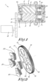
- FIG 1 schematically shows a compressor device according to the invention, which in this case is a screw compressor device 1 provided with a compressor element 2. It is possible that the screw compressor device 1 is provided with more than one such compressor element 2.
- the compressor element 2 comprises a housing 3 in which two rotors 4, 5 are mounted with their shafts 6, 7 on bearings. These rotors 4, 5 are so-called screw rotors, i.e. a male screw rotor 4 and a female screw rotor 5, with lobes 8 that can rotate cooperatively into each other.
- a first driving gear wheel 9 is provided that can engage with a second driving gear wheel 10, whereby said second gear wheel 10 is mounted on a shaft 11 of a drive 12.
- Said drive 12 is an electric motor for example.
- the driving gear wheel 9 is mounted on the male rotor 5, but it can also be mounted on the female rotor 4.
- Said gear wheels 13 and 14 are typically provided with a straight cut gear mesh 15 on their relevant rims 16.
- Said gear wheels 9 and 10 are provided with a slanted gear mesh. Obviously it is also possible that all gear wheels 9, 10, 13 and 14 have a straight cut gear mesh or that they all have a slanted gear mesh or another combination.
- the transmission between the electric motor 12 and the driven rotor 5 is provided completely by the driving gear wheels 9, 10.
- One of said driving gear wheels 10 is provided with spokes 17 as shown in figures 2 and 3 , which are mounted between the rim 16 with the gear mesh 15 and the gear hub 18 of the gear wheel 10, whereby between the spokes 17 free spaces 19 are located which extend between the rim 16 and the gear hub 18.
- FIGS 2 and 3 clearly show that the driving gear wheel 10 is provided with eight spokes 17 in this case which extend from the hub 18 to the rim 16.
- At least one of said free spaces 19 is filled with a block 20 or core made of a rigid, incompressible material.
- the block 20 is preferably made of, for example, aluminium or polyurethane, but other metal or synthetics are also possible.
- a viscoelastic material 21 is located between the gear wheel 10 on the one hand and the block 20 on the other hand.
- the viscoelastic material 21 is in this case, but not necessarily, made of rubber.
- This rubber can be both natural and synthetic, but other materials can also be applied, such as neoprene.
- viscoelastic material 21 is mounted between on the one hand the block 20, and, on the other hand, the rim 16 and the gear hub 18.
- Said viscoelastic material 21 will cause damping by shear in said material 21 and thus reduce the vibration in the mode shapes.
- viscoelastic material 21 is also mounted between the spokes 17 and the block 20.
- Said viscoelastic material 21 will cause damping by tension loads in said material 21.
- viscoelastic material 21 is located between the spokes 17 and the block 20, whereby no viscoelastic material 21 is provided between the block 20 on the one hand and the rim 16 and the gear hub 18, on the other hand .
- viscoelastic material 21 is located between the block 20 on the one hand and the rim 16 and the gear hub 18, on the other hand, whereby no viscoelastic material 21 is provided between the spokes 17 and the block 21.
- the amount of viscoelastic material 21 which is provided depends on the damping which is desired or necessary for the relevant application.
- the viscoelastic material 21 takes on the form of a number of O-rings 22, in this case four. But this could also only be one, two, three or more than four O-rings.
- Said O-rings are tensioned around the block 20 as it were.
- the block 20 is preferably provided with a groove 23 or recess provided for this purpose.
- the viscoelastic material 21 is at least partially compressed, this means: even without any torsional or vibrational load the viscoelastic material 21 is already partially compressed.
- Such embodiment will be comparable to the embodiment as shown in figure 3 , with the difference that there will be no viscoelastic material 21.
- the operation of the screw compressor device 1 and the gear wheel 10 is very simple and as follows.
- the drive 12 will drive the second driving gear wheel 10.
- the operation of the gear wheels will also set in motion the first driving gear wheel 9.
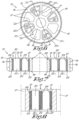
- Figure 7 shows a cross-section of the blocks 20 which are divided perpendicular to the spokes 17.
- Figure 8 shows a cross-section of a block 20 that is divided parallel with the spokes 17.
- Viscoelastic material 21 is mounted between the different partial blocks 20a, 20b.
- the pads 24 can be mounted between the blocks 20 or between a block 20 and the gear wheel 10, whereby they are mounted around the relevant block 20 or partial block 20a, 20b.
- the pads 24 are, as in the previous embodiment, mounted in recesses 23 provided for this purpose, but this is not necessarily the case.
- pads 24 are constructed of different separate strips.
- the viscoelastic material 21 in the form of the pads 24 is at least partially compressed.
- Figure 9 shows a variant embodiment of figure 2 , whereby the blocks 20 are mounted on a disk 25 or plate.
- said blocks 20 together with said disk 25 form one whole, this means: that they are made of one piece of material.
- the disk 25 is located next to the gear wheel 10. It is also possible that the disk 25 is located against the gear wheel 10.
- Figures 10a and 10b show another two variants of figure 3 .
- the blocks 20 are in direct contact with the gear hub 18. This means that no viscoelastic material 21 is located between a block 20 and the gear hub 18.
- the blocks 20 are even part of the gear hub 18 or, in other words, they form one whole with it
- viscoelastic material 21 is mounted between the blocks 20, on the one hand, and the spokes 17 and rim 16, on the other hand.
- Figure 10b shows a same embodiment, but here the form of the blocks 20 is different. In this case there is a protrusion 26 on the rim 16 and an associated recess 27 in the blocks 20. Consequently, the blocks 20 have a sort of V-shaped cross-section.
- Figure 11 shows a variant embodiment of figure 6 , whereby the second driving gear wheel 10 is in this case provided with a number of partial spokes 28, which are only connected to the gear hub 18. In other words, they do not extend from the gear hub 18 up to the rim 16 in the same way as the spokes 17.
- the blocks 20 are placed in the space between a partial spoke 28 and a spoke 17.
- the viscoelastic material 21 is mounted between the blocks 20 on the one hand and the rim 16, the gear hub 18, the spokes 17 and/or the partial spokes 28 on the other hand.
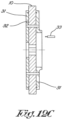
- Figures 12a, 12b and 12c show a last variant of a gear wheel 10 according to the invention.
- grooves 29 are located between the gear wheel 10 on the one hand and the block 20 on the other hand.
- the width, or thickness, of the grooves is preferably less than 1 millimetre.
- Said grooves are practically realised by for instance EDM or wire electrical discharge machining, and as a result of this possess a bulge 30 on their end.
- the grooves 29 are filled with a fluid.
- This fluid possesses viscous properties and is for example, but not necessarily, oil.
- the gear wheel 10 is provided with two cover plates 31 in this case, one on each side of the gear wheel 10, to close the grooves 29.
- cover plate 31 or cover plates 31 are provided with drain channels or drain openings for the fluid.
- Figure 12c schematically shows such drain channel 32.
- the drain channel 32 extends perpendicularly through the cover plate 31, from the side of the cover plate 31 oriented to the gear wheel 10 in a location located near the grooves 29 to the other side of the cover plate 31, i.e. the side of the cover plate 31 facing away from the gear wheel 10.
- drain channel 32 is in connection with the groove 29 such that a fluid, such as for example oil, can flow from the groove 29 to the drain channel 32.
- such drain channel 32 will be provided for every groove 29.
- drain channel 32 is drawn as a straight channel, which extends in a direction perpendicular to the plane of the cover plate 31, it is not excluded that the drain channel 32 is oriented differently.
- Such gear wheel from figures 12a, 12b and 12c will be applied in a compressor device which is provided with an oil-injection circuit with a nozzle 33 or the like which can inject oil in the grooves 29 of the gear wheel 10.
- the cover plates 31 will ensure that the oil remains in the grooves 29, whereby the oil can flow out via the drain channel 32. The oil that flows out is then quickly refilled by injecting new oil with the nozzle 33.
- the heat which is inevitably generated during the operation of the compressor device 1 will ensure that the viscosity of the oil reduces, such that the damping will decrease.
- the speeds of the compressor device 1 for which such vibrations or resonances occur can be pre-defined and the flow of the oil-injection can be regulated to inject oil when the compressor device 1 runs at said speeds, but it is also possible to perform real time measurements of the vibrations or resonances during the operation of the compressor device 1 and regulate the oil injection based on such measurement.
- gear wheel according to the invention is applied in a transmission of a screw compressor, it is not excluded that the gear wheel is applied in other machines.
- the invention is not restricted either to application of a gear wheel according to the invention as a second driving gear wheel, but another gear wheel or a combination of gear wheels of the compressor device can also be executed in this way.
Landscapes
- Engineering & Computer Science (AREA)
- General Engineering & Computer Science (AREA)
- Mechanical Engineering (AREA)
- Physics & Mathematics (AREA)
- Acoustics & Sound (AREA)
- Aviation & Aerospace Engineering (AREA)
- Gears, Cams (AREA)
- Structures Of Non-Positive Displacement Pumps (AREA)
- Compressors, Vaccum Pumps And Other Relevant Systems (AREA)
- Vibration Prevention Devices (AREA)
- Applications Or Details Of Rotary Compressors (AREA)
Applications Claiming Priority (2)
| Application Number | Priority Date | Filing Date | Title |
|---|---|---|---|
| BE20205069A BE1028031B1 (nl) | 2020-02-06 | 2020-02-06 | Tandwiel en compressorinrichting uitgerust met dergelijk tandwiel |
| PCT/IB2021/050894 WO2021156778A1 (en) | 2020-02-06 | 2021-02-04 | Gear wheel and compressor device equipped with such a gear wheel |
Publications (2)
| Publication Number | Publication Date |
|---|---|
| EP4100662A1 EP4100662A1 (en) | 2022-12-14 |
| EP4100662B1 true EP4100662B1 (en) | 2025-04-09 |
Family
ID=69591514
Family Applications (1)
| Application Number | Title | Priority Date | Filing Date |
|---|---|---|---|
| EP21708374.0A Active EP4100662B1 (en) | 2020-02-06 | 2021-02-04 | Gear wheel and compressor device equipped with such a gear wheel |
Country Status (12)
| Country | Link |
|---|---|
| US (1) | US12276316B2 (da) |
| EP (1) | EP4100662B1 (da) |
| JP (1) | JP7788387B2 (da) |
| KR (1) | KR102770288B1 (da) |
| CN (2) | CN115053084A (da) |
| BE (1) | BE1028031B1 (da) |
| BR (1) | BR112022015535A2 (da) |
| CA (1) | CA3165041A1 (da) |
| DK (1) | DK4100662T3 (da) |
| ES (1) | ES3035602T3 (da) |
| FI (1) | FI4100662T3 (da) |
| WO (1) | WO2021156778A1 (da) |
Families Citing this family (2)
| Publication number | Priority date | Publication date | Assignee | Title |
|---|---|---|---|---|
| DE102024128732A1 (de) | 2024-10-04 | 2026-04-09 | Kaeser Kompressoren Se | Drehelastisches Zahnrad und Getriebeanordnung für einen Schraubenverdichter |
| CN119353395B (zh) * | 2024-11-18 | 2025-11-21 | 中国船舶集团有限公司第七0三研究所 | 一种可调多谐振点的减振齿轮及其设计方法 |
Family Cites Families (31)
| Publication number | Priority date | Publication date | Assignee | Title |
|---|---|---|---|---|
| US2159235A (en) * | 1934-04-04 | 1939-05-23 | Gen Motors Corp | Torsional vibration suppressor |
| US2446942A (en) * | 1942-11-18 | 1948-08-10 | Packard Motor Car Co | Elastic rotational system |
| GB1033894A (en) * | 1962-06-21 | 1966-06-22 | Yarsley Res Lab Ltd | Improvements in or relating to flexible couplings and the like |
| AT239612B (de) | 1962-10-29 | 1965-04-12 | Geislinger Dr Ing Leonard | Schwingungsdämpfer für Torsionsschwingungen |
| US3385127A (en) * | 1963-03-06 | 1968-05-28 | Shin Mitsubishi Jukogyo Kk | Gears formed of sheet metal and liquids |
| US3857296A (en) * | 1971-07-23 | 1974-12-31 | Garbo P | Vibration-damped rotatable drive member |
| US3940947A (en) * | 1972-06-26 | 1976-03-02 | S.R.M. Hydromekanik Aktiebolag | Resilient driving connections |
| DE2455385A1 (de) * | 1974-11-22 | 1976-05-26 | Metzeler Gummitechnik | Drehschwingungsdaempfer |
| US4174643A (en) * | 1977-09-08 | 1979-11-20 | Kotaro Tsukamoto | Silent gear wheel |
| DE3535859A1 (de) * | 1985-10-08 | 1987-04-09 | Schaeffler Waelzlager Kg | Riemenscheibe mit daempfungselement |
| SE468131B (sv) * | 1991-04-10 | 1992-11-09 | Volvo Ab | Anordning vid foerbraenningsmotor |
| US5452622A (en) * | 1993-02-09 | 1995-09-26 | Magi, L.P. | Stress dissipation gear |
| US5931052A (en) | 1996-06-13 | 1999-08-03 | Simpson International (Uk) Ltd. | Crankshaft gear torsional vibration isolator assembly for an engine |
| DE19958036A1 (de) * | 1999-12-04 | 2001-06-07 | Optimer Polymer Technik Gmbh | Federelement, vorzugsweise Torsionsdämpfer, insb. für Vorrichtungen zum Heben und Senken von Kraftfahrzeugfensterscheiben |
| JP4289174B2 (ja) * | 2004-02-27 | 2009-07-01 | コニカミノルタビジネステクノロジーズ株式会社 | 回転体の駆動装置及び画像形成装置 |
| GB0607502D0 (en) * | 2006-04-13 | 2006-05-24 | Boc Group Plc | A gear |
| US8091450B2 (en) * | 2007-09-26 | 2012-01-10 | Metavation, Llc | Decoupled vibration damper |
| US8117943B2 (en) * | 2007-09-26 | 2012-02-21 | Metavation, Llc | Decoupled vibration damper |
| DE102008059042A1 (de) * | 2008-11-26 | 2010-05-27 | SGF SüDDEUTSCHE GELENKSCHEIBENFABRIK GMBH & CO. KG | Vorrichtung zum schwingungsreduzierten Übertragen von Drehmomenten |
| CN101813177B (zh) * | 2009-02-20 | 2014-05-07 | 卡特彼勒公司 | 柔性齿轮传动装置、发动机和传动机构操作方法 |
| DE102009049928A1 (de) | 2009-10-19 | 2011-04-21 | Kendrion Linnig Gmbh | Vorrichtung zur Schwingungsdämpfung in einem Getriebe |
| JP5777379B2 (ja) * | 2011-04-05 | 2015-09-09 | 株式会社日立産機システム | 空気圧縮機 |
| KR101366107B1 (ko) * | 2013-08-09 | 2014-03-12 | 케이아이엠씨(주) | 축진동 유압식 진동 댐퍼 겸용 유연 커플링 |
| BR112017020953B1 (pt) * | 2015-03-30 | 2023-02-07 | Dayco Ip Holdings, Llc | Amortecedor de vibração torsional, sistema de acionamento de acessórios de extremidade frontal e métodos para projeto de um raio para um amortecedor de vibração torsional |
| US9593741B2 (en) * | 2015-05-08 | 2017-03-14 | E-Aam Driveline Systems Ab | Transmission with torsional damper |
| US10145444B2 (en) * | 2016-07-25 | 2018-12-04 | Ford Global Technologies, Llc | Systems for a crankshaft damper cover |
| DE102017204146A1 (de) * | 2017-03-14 | 2018-09-20 | Bayerische Motoren Werke Aktiengesellschaft | Torsionsschwingungsdämpfer sowie Antriebsstrang für ein Fahrzeug |
| CN108688403A (zh) * | 2017-04-03 | 2018-10-23 | Tvs电机股份有限公司 | 用于车辆的阻尼构件 |
| BE1026106B1 (nl) * | 2017-08-28 | 2019-10-16 | Atlas Copco Airpower Naamloze Vennootschap | Schroefcompressor |
| US11028897B2 (en) * | 2018-01-16 | 2021-06-08 | Litens Automotive Partnership | Torsional vibration damper and method of making same |
| WO2019152903A1 (en) * | 2018-02-02 | 2019-08-08 | Parker-Hannifin Corporation | Integrated gear and torsional vibration damper assembly |
-
2020
- 2020-02-06 BE BE20205069A patent/BE1028031B1/nl active IP Right Grant
-
2021
- 2021-02-04 FI FIEP21708374.0T patent/FI4100662T3/fi active
- 2021-02-04 KR KR1020227029001A patent/KR102770288B1/ko active Active
- 2021-02-04 DK DK21708374.0T patent/DK4100662T3/da active
- 2021-02-04 JP JP2022547309A patent/JP7788387B2/ja active Active
- 2021-02-04 ES ES21708374T patent/ES3035602T3/es active Active
- 2021-02-04 WO PCT/IB2021/050894 patent/WO2021156778A1/en not_active Ceased
- 2021-02-04 CA CA3165041A patent/CA3165041A1/en active Pending
- 2021-02-04 CN CN202180012928.XA patent/CN115053084A/zh active Pending
- 2021-02-04 BR BR112022015535A patent/BR112022015535A2/pt unknown
- 2021-02-04 CN CN202510876959.XA patent/CN120701724A/zh active Pending
- 2021-02-04 US US17/797,271 patent/US12276316B2/en active Active
- 2021-02-04 EP EP21708374.0A patent/EP4100662B1/en active Active
Also Published As
| Publication number | Publication date |
|---|---|
| FI4100662T3 (fi) | 2025-07-10 |
| JP7788387B2 (ja) | 2025-12-18 |
| US12276316B2 (en) | 2025-04-15 |
| BE1028031B1 (nl) | 2021-09-07 |
| CN120701724A (zh) | 2025-09-26 |
| US20230052482A1 (en) | 2023-02-16 |
| CA3165041A1 (en) | 2021-08-12 |
| DK4100662T3 (da) | 2025-07-21 |
| ES3035602T3 (en) | 2025-09-05 |
| JP2023513151A (ja) | 2023-03-30 |
| KR102770288B1 (ko) | 2025-02-20 |
| EP4100662A1 (en) | 2022-12-14 |
| CN115053084A (zh) | 2022-09-13 |
| BR112022015535A2 (pt) | 2022-09-27 |
| KR20220130770A (ko) | 2022-09-27 |
| WO2021156778A1 (en) | 2021-08-12 |
| BE1028031A1 (nl) | 2021-08-30 |
Similar Documents
| Publication | Publication Date | Title |
|---|---|---|
| US12510070B2 (en) | Systems and method for use of single mass flywheel alongside torsional vibration damper assembly for single acting reciprocating pump | |
| EP4100662B1 (en) | Gear wheel and compressor device equipped with such a gear wheel | |
| Mancuso et al. | What are the differences in high performance flexible couplings for turbomachinery? | |
| EP2005033A1 (en) | A gear | |
| US3866480A (en) | Orbital vibrator | |
| JP2006038227A (ja) | 振動絶縁のための装置 | |
| WO2023204915A1 (en) | Vehicle driveline component having a lubrication de-aerator | |
| EP2307260A1 (en) | Rotational testing system | |
| CN102913606A (zh) | 柔性传动减速齿轮箱 | |
| CN102094826A (zh) | 一种涡旋压缩机的平面十字联轴节 | |
| CN103343783A (zh) | 一种用于机械增压器的联轴器结构 | |
| AU2022325410B2 (en) | Compressor assembly | |
| EP4077879B1 (en) | Compressor device and device equipped with a bearing damper | |
| RU2304688C2 (ru) | Героторный гидравлический двигатель или насос | |
| RU2295023C1 (ru) | Турбовинтовой забойный двигатель | |
| Bloch et al. | Industrial Drive Couplings | |
| US20100326222A1 (en) | Vibration exciter | |
| Ro¨ ßler | The Geislinger Steel Spring Coupling to Lower Torsional Vibrations | |
| CN223908652U (zh) | 一种联轴器用梅花弹性结构 | |
| US20250198451A1 (en) | Rotational element and compressor assembly comprising such a rotational element | |
| KR20120076030A (ko) | 압축기 | |
| Stephens et al. | Dampers for Controlling Vibration in Reciprocating Compressor Systems | |
| CN108098541B (zh) | 一种单臂式磨床 | |
| SU1103907A1 (ru) | Вибровозбудитель | |
| CN1938530A (zh) | 齿轮传动装置 |
Legal Events
| Date | Code | Title | Description |
|---|---|---|---|
| STAA | Information on the status of an ep patent application or granted ep patent |
Free format text: STATUS: UNKNOWN |
|
| STAA | Information on the status of an ep patent application or granted ep patent |
Free format text: STATUS: THE INTERNATIONAL PUBLICATION HAS BEEN MADE |
|
| PUAI | Public reference made under article 153(3) epc to a published international application that has entered the european phase |
Free format text: ORIGINAL CODE: 0009012 |
|
| STAA | Information on the status of an ep patent application or granted ep patent |
Free format text: STATUS: REQUEST FOR EXAMINATION WAS MADE |
|
| 17P | Request for examination filed |
Effective date: 20220817 |
|
| AK | Designated contracting states |
Kind code of ref document: A1 Designated state(s): AL AT BE BG CH CY CZ DE DK EE ES FI FR GB GR HR HU IE IS IT LI LT LU LV MC MK MT NL NO PL PT RO RS SE SI SK SM TR |
|
| DAV | Request for validation of the european patent (deleted) | ||
| DAX | Request for extension of the european patent (deleted) | ||
| GRAP | Despatch of communication of intention to grant a patent |
Free format text: ORIGINAL CODE: EPIDOSNIGR1 |
|
| STAA | Information on the status of an ep patent application or granted ep patent |
Free format text: STATUS: GRANT OF PATENT IS INTENDED |
|
| INTG | Intention to grant announced |
Effective date: 20241021 |
|
| GRAS | Grant fee paid |
Free format text: ORIGINAL CODE: EPIDOSNIGR3 |
|
| GRAA | (expected) grant |
Free format text: ORIGINAL CODE: 0009210 |
|
| STAA | Information on the status of an ep patent application or granted ep patent |
Free format text: STATUS: THE PATENT HAS BEEN GRANTED |
|
| AK | Designated contracting states |
Kind code of ref document: B1 Designated state(s): AL AT BE BG CH CY CZ DE DK EE ES FI FR GB GR HR HU IE IS IT LI LT LU LV MC MK MT NL NO PL PT RO RS SE SI SK SM TR |
|
| REG | Reference to a national code |
Ref country code: GB Ref legal event code: FG4D |
|
| REG | Reference to a national code |
Ref country code: CH Ref legal event code: EP |
|
| REG | Reference to a national code |
Ref country code: DE Ref legal event code: R096 Ref document number: 602021028869 Country of ref document: DE |
|
| REG | Reference to a national code |
Ref country code: IE Ref legal event code: FG4D |
|
| REG | Reference to a national code |
Ref country code: FI Ref legal event code: FGE |
|
| REG | Reference to a national code |
Ref country code: DK Ref legal event code: T3 Effective date: 20250715 |
|
| REG | Reference to a national code |
Ref country code: NL Ref legal event code: FP |
|
| REG | Reference to a national code |
Ref country code: SE Ref legal event code: TRGR |
|
| REG | Reference to a national code |
Ref country code: ES Ref legal event code: FG2A Ref document number: 3035602 Country of ref document: ES Kind code of ref document: T3 Effective date: 20250905 |
|
| REG | Reference to a national code |
Ref country code: AT Ref legal event code: MK05 Ref document number: 1783751 Country of ref document: AT Kind code of ref document: T Effective date: 20250409 |
|
| P01 | Opt-out of the competence of the unified patent court (upc) registered |
Free format text: CASE NUMBER: UPC_APP_4965_4100662/2025 Effective date: 20250827 |
|
| PG25 | Lapsed in a contracting state [announced via postgrant information from national office to epo] |
Ref country code: PT Free format text: LAPSE BECAUSE OF FAILURE TO SUBMIT A TRANSLATION OF THE DESCRIPTION OR TO PAY THE FEE WITHIN THE PRESCRIBED TIME-LIMIT Effective date: 20250811 |
|
| REG | Reference to a national code |
Ref country code: LT Ref legal event code: MG9D |
|
| PG25 | Lapsed in a contracting state [announced via postgrant information from national office to epo] |
Ref country code: NO Free format text: LAPSE BECAUSE OF FAILURE TO SUBMIT A TRANSLATION OF THE DESCRIPTION OR TO PAY THE FEE WITHIN THE PRESCRIBED TIME-LIMIT Effective date: 20250709 Ref country code: GR Free format text: LAPSE BECAUSE OF FAILURE TO SUBMIT A TRANSLATION OF THE DESCRIPTION OR TO PAY THE FEE WITHIN THE PRESCRIBED TIME-LIMIT Effective date: 20250710 |
|
| PG25 | Lapsed in a contracting state [announced via postgrant information from national office to epo] |
Ref country code: PL Free format text: LAPSE BECAUSE OF FAILURE TO SUBMIT A TRANSLATION OF THE DESCRIPTION OR TO PAY THE FEE WITHIN THE PRESCRIBED TIME-LIMIT Effective date: 20250409 |
|
| PG25 | Lapsed in a contracting state [announced via postgrant information from national office to epo] |
Ref country code: BG Free format text: LAPSE BECAUSE OF FAILURE TO SUBMIT A TRANSLATION OF THE DESCRIPTION OR TO PAY THE FEE WITHIN THE PRESCRIBED TIME-LIMIT Effective date: 20250409 |
|
| PG25 | Lapsed in a contracting state [announced via postgrant information from national office to epo] |
Ref country code: HR Free format text: LAPSE BECAUSE OF FAILURE TO SUBMIT A TRANSLATION OF THE DESCRIPTION OR TO PAY THE FEE WITHIN THE PRESCRIBED TIME-LIMIT Effective date: 20250409 |
|
| PG25 | Lapsed in a contracting state [announced via postgrant information from national office to epo] |
Ref country code: AT Free format text: LAPSE BECAUSE OF FAILURE TO SUBMIT A TRANSLATION OF THE DESCRIPTION OR TO PAY THE FEE WITHIN THE PRESCRIBED TIME-LIMIT Effective date: 20250409 |
|
| PG25 | Lapsed in a contracting state [announced via postgrant information from national office to epo] |
Ref country code: RS Free format text: LAPSE BECAUSE OF FAILURE TO SUBMIT A TRANSLATION OF THE DESCRIPTION OR TO PAY THE FEE WITHIN THE PRESCRIBED TIME-LIMIT Effective date: 20250709 |
|
| PG25 | Lapsed in a contracting state [announced via postgrant information from national office to epo] |
Ref country code: IS Free format text: LAPSE BECAUSE OF FAILURE TO SUBMIT A TRANSLATION OF THE DESCRIPTION OR TO PAY THE FEE WITHIN THE PRESCRIBED TIME-LIMIT Effective date: 20250809 |
|
| PG25 | Lapsed in a contracting state [announced via postgrant information from national office to epo] |
Ref country code: LV Free format text: LAPSE BECAUSE OF FAILURE TO SUBMIT A TRANSLATION OF THE DESCRIPTION OR TO PAY THE FEE WITHIN THE PRESCRIBED TIME-LIMIT Effective date: 20250409 |
|
| REG | Reference to a national code |
Ref country code: DE Ref legal event code: R097 Ref document number: 602021028869 Country of ref document: DE |
|
| PG25 | Lapsed in a contracting state [announced via postgrant information from national office to epo] |
Ref country code: SM Free format text: LAPSE BECAUSE OF FAILURE TO SUBMIT A TRANSLATION OF THE DESCRIPTION OR TO PAY THE FEE WITHIN THE PRESCRIBED TIME-LIMIT Effective date: 20250409 |
|
| PG25 | Lapsed in a contracting state [announced via postgrant information from national office to epo] |
Ref country code: CZ Free format text: LAPSE BECAUSE OF FAILURE TO SUBMIT A TRANSLATION OF THE DESCRIPTION OR TO PAY THE FEE WITHIN THE PRESCRIBED TIME-LIMIT Effective date: 20250409 |
|
| PG25 | Lapsed in a contracting state [announced via postgrant information from national office to epo] |
Ref country code: EE Free format text: LAPSE BECAUSE OF FAILURE TO SUBMIT A TRANSLATION OF THE DESCRIPTION OR TO PAY THE FEE WITHIN THE PRESCRIBED TIME-LIMIT Effective date: 20250409 |
|
| PG25 | Lapsed in a contracting state [announced via postgrant information from national office to epo] |
Ref country code: SK Free format text: LAPSE BECAUSE OF FAILURE TO SUBMIT A TRANSLATION OF THE DESCRIPTION OR TO PAY THE FEE WITHIN THE PRESCRIBED TIME-LIMIT Effective date: 20250409 |
|
| PLBE | No opposition filed within time limit |
Free format text: ORIGINAL CODE: 0009261 |
|
| STAA | Information on the status of an ep patent application or granted ep patent |
Free format text: STATUS: NO OPPOSITION FILED WITHIN TIME LIMIT |
|
| REG | Reference to a national code |
Ref country code: CH Ref legal event code: L10 Free format text: ST27 STATUS EVENT CODE: U-0-0-L10-L00 (AS PROVIDED BY THE NATIONAL OFFICE) Effective date: 20260218 |
|
| REG | Reference to a national code |
Ref country code: CH Ref legal event code: U11 Free format text: ST27 STATUS EVENT CODE: U-0-0-U10-U11 (AS PROVIDED BY THE NATIONAL OFFICE) Effective date: 20260301 |
|
| PGFP | Annual fee paid to national office [announced via postgrant information from national office to epo] |
Ref country code: NL Payment date: 20260226 Year of fee payment: 6 |
|
| 26N | No opposition filed |
Effective date: 20260112 |
|
| PGFP | Annual fee paid to national office [announced via postgrant information from national office to epo] |
Ref country code: SE Payment date: 20260227 Year of fee payment: 6 |
|
| PGFP | Annual fee paid to national office [announced via postgrant information from national office to epo] |
Ref country code: GB Payment date: 20260227 Year of fee payment: 6 |
|
| PGFP | Annual fee paid to national office [announced via postgrant information from national office to epo] |
Ref country code: ES Payment date: 20260302 Year of fee payment: 6 |
|
| PGFP | Annual fee paid to national office [announced via postgrant information from national office to epo] |
Ref country code: DK Payment date: 20260225 Year of fee payment: 6 Ref country code: DE Payment date: 20260227 Year of fee payment: 6 |
|
| PGFP | Annual fee paid to national office [announced via postgrant information from national office to epo] |
Ref country code: FI Payment date: 20260225 Year of fee payment: 6 Ref country code: BE Payment date: 20260227 Year of fee payment: 6 Ref country code: IT Payment date: 20260219 Year of fee payment: 6 |
|
| PGFP | Annual fee paid to national office [announced via postgrant information from national office to epo] |
Ref country code: FR Payment date: 20260225 Year of fee payment: 6 |
|
| PGFP | Annual fee paid to national office [announced via postgrant information from national office to epo] |
Ref country code: TR Payment date: 20260127 Year of fee payment: 6 |
|
| PGFP | Annual fee paid to national office [announced via postgrant information from national office to epo] |
Ref country code: CH Payment date: 20260301 Year of fee payment: 6 |