EP4100653B1 - Stabilisatorkanal eines verdichters - Google Patents
Stabilisatorkanal eines verdichters Download PDFInfo
- Publication number
- EP4100653B1 EP4100653B1 EP21702274.8A EP21702274A EP4100653B1 EP 4100653 B1 EP4100653 B1 EP 4100653B1 EP 21702274 A EP21702274 A EP 21702274A EP 4100653 B1 EP4100653 B1 EP 4100653B1
- Authority
- EP
- European Patent Office
- Prior art keywords
- channel
- stabilizer
- compressor
- flow
- guiding elements
- Prior art date
- Legal status (The legal status is an assumption and is not a legal conclusion. Google has not performed a legal analysis and makes no representation as to the accuracy of the status listed.)
- Active
Links
Images


Classifications
-
- F—MECHANICAL ENGINEERING; LIGHTING; HEATING; WEAPONS; BLASTING
- F04—POSITIVE - DISPLACEMENT MACHINES FOR LIQUIDS; PUMPS FOR LIQUIDS OR ELASTIC FLUIDS
- F04D—NON-POSITIVE-DISPLACEMENT PUMPS
- F04D29/00—Details, component parts, or accessories
- F04D29/40—Casings; Connections of working fluid
- F04D29/42—Casings; Connections of working fluid for radial or helico-centrifugal pumps
- F04D29/4206—Casings; Connections of working fluid for radial or helico-centrifugal pumps especially adapted for elastic fluid pumps
- F04D29/4213—Casings; Connections of working fluid for radial or helico-centrifugal pumps especially adapted for elastic fluid pumps suction ports
-
- F—MECHANICAL ENGINEERING; LIGHTING; HEATING; WEAPONS; BLASTING
- F04—POSITIVE - DISPLACEMENT MACHINES FOR LIQUIDS; PUMPS FOR LIQUIDS OR ELASTIC FLUIDS
- F04D—NON-POSITIVE-DISPLACEMENT PUMPS
- F04D29/00—Details, component parts, or accessories
- F04D29/66—Combating cavitation, whirls, noise, vibration or the like; Balancing
- F04D29/68—Combating cavitation, whirls, noise, vibration or the like; Balancing by influencing boundary layers
- F04D29/681—Combating cavitation, whirls, noise, vibration or the like; Balancing by influencing boundary layers especially adapted for elastic fluid pumps
- F04D29/682—Combating cavitation, whirls, noise, vibration or the like; Balancing by influencing boundary layers especially adapted for elastic fluid pumps by fluid extraction
-
- F—MECHANICAL ENGINEERING; LIGHTING; HEATING; WEAPONS; BLASTING
- F04—POSITIVE - DISPLACEMENT MACHINES FOR LIQUIDS; PUMPS FOR LIQUIDS OR ELASTIC FLUIDS
- F04D—NON-POSITIVE-DISPLACEMENT PUMPS
- F04D29/00—Details, component parts, or accessories
- F04D29/66—Combating cavitation, whirls, noise, vibration or the like; Balancing
- F04D29/68—Combating cavitation, whirls, noise, vibration or the like; Balancing by influencing boundary layers
- F04D29/681—Combating cavitation, whirls, noise, vibration or the like; Balancing by influencing boundary layers especially adapted for elastic fluid pumps
- F04D29/685—Inducing localised fluid recirculation in the stator-rotor interface
-
- F—MECHANICAL ENGINEERING; LIGHTING; HEATING; WEAPONS; BLASTING
- F05—INDEXING SCHEMES RELATING TO ENGINES OR PUMPS IN VARIOUS SUBCLASSES OF CLASSES F01-F04
- F05D—INDEXING SCHEME FOR ASPECTS RELATING TO NON-POSITIVE-DISPLACEMENT MACHINES OR ENGINES, GAS-TURBINES OR JET-PROPULSION PLANTS
- F05D2220/00—Application
- F05D2220/40—Application in turbochargers
-
- Y—GENERAL TAGGING OF NEW TECHNOLOGICAL DEVELOPMENTS; GENERAL TAGGING OF CROSS-SECTIONAL TECHNOLOGIES SPANNING OVER SEVERAL SECTIONS OF THE IPC; TECHNICAL SUBJECTS COVERED BY FORMER USPC CROSS-REFERENCE ART COLLECTIONS [XRACs] AND DIGESTS
- Y02—TECHNOLOGIES OR APPLICATIONS FOR MITIGATION OR ADAPTATION AGAINST CLIMATE CHANGE
- Y02T—CLIMATE CHANGE MITIGATION TECHNOLOGIES RELATED TO TRANSPORTATION
- Y02T10/00—Road transport of goods or passengers
- Y02T10/10—Internal combustion engine [ICE] based vehicles
- Y02T10/12—Improving ICE efficiencies
Definitions
- the invention relates to the field of compressors, in particular radial compressors and diagonal compressors.
- the invention relates to a stabilizer channel at the compressor inlet for improving the characteristic map width and the characteristic curve slope of a compressor stage.
- Exhaust gas turbochargers are used to increase the performance of internal combustion engines, especially reciprocating piston engines.
- An exhaust gas turbocharger typically has a radial or diagonal compressor and a radial or axial turbine.
- a bypass in the form of an annular cavity can be provided within the compressor housing above the impeller contour, parallel to the intake duct.
- a bypass is also known as a stabilizer chamber or recirculator. known.
- the mass flow at the compressor wheel inlet near the surge line can be artificially increased.
- a portion of the mass flow is diverted from the compressor wheel into the side chamber (bypass).
- This mass flow exhibits a strong swirl component (in the direction of rotation of the impeller - co-swirl). This co-swirl reduces the work conversion in the compressor, resulting in flat characteristic curves near the surge line.
- the printed publication SU 478 957 A2 describes an inflow area of a compressor stage with an annular cavity in the compressor housing.
- the publication EP 2 434 165 A1 describes a compressor of an exhaust gas turbocharger in which the structure of the inlet slot, the outlet slot, and the return channel can be formed simultaneously when the compressor housing of a split type is assembled.
- the publication DE 101 05 456 A1 describes a compressor for an internal combustion engine having a compressor housing with a flow channel structure and a recirculation arrangement with a bypass structure for recirculating part of the air entering the compressor wheel.
- the object of the present invention is to provide a stabilizer channel of a compressor, in particular a radial compressor or diagonal compressor, which is improved with respect to at least one of the disadvantages known from the prior art. Furthermore, the object of the present invention is to provide an improved compressor and an improved turbocharger.
- a stabilizer channel of a compressor in particular a radial compressor or diagonal compressor, is provided according to independent claim 1. Furthermore, a compressor with a stabilizer channel according to the herein described embodiments and a turbocharger with such a compressor are provided.
- a stabilizer duct of a compressor in particular a radial compressor or diagonal compressor, is provided according to claim 1.
- the stabilizer duct comprises an annular stabilizer chamber which surrounds a main flow duct in the intake region of a compressor wheel and is delimited from the main flow duct by an annular web.
- the annular stabilizer chamber is vaneless and communicates via a downstream inlet duct and an upstream outlet opening.
- Several flow guide elements are arranged in the downstream inlet duct.
- the downstream inlet duct is arranged between an upstream part of the annular web and a downstream part of the annular web.
- a stabilizer duct is advantageously provided that enables an improvement in the characteristic map width and the characteristic curve slope of a compressor stage. Furthermore, the stabilizer duct according to the invention with flow guide elements in the downstream inlet duct can provide a stabilizer duct that has advantages over conventional stabilizers known from the prior art in terms of component integration, containment properties, and manufacturing costs.
- a compressor in particular a radial compressor or a diagonal compressor, is provided according to claim 14.
- a compressor with improved characteristic map width and characteristic curve slope be provided.
- Figure 1 shows a schematic view of a stabilizer channel 10 according to the prior art.
- Figure 1 A section through a housing of a radial compressor, taken along the rotational axis 11 of the compressor wheel 21, such as is used for compressing air in exhaust gas turbochargers.
- a stabilizer chamber 12 is arranged in the compressor housing 5.
- the stabilizer chamber 12 is connected to the main flow channel 13 via an inlet channel 15 and an outlet opening 16.
- the stabilizer chamber 12 is separated from the main flow channel 13 by an annular web 14.
- Retaining ribs 121 are arranged in the stabilizer chamber 12 and connect the annular web 14 to the compressor housing.
- the compressor may be a radial compressor or a diagonal compressor.
- the stabilizer channel 10 comprises an annular stabilizer chamber 12 surrounding a main flow channel 13 in the intake region of a compressor wheel 21.
- the stabilizer channel 10 is typically arranged at the compressor inlet.
- a "stabilizer channel” is understood to mean, in particular, a channel in the compressor inlet that is configured to improve the characteristic map width of a compressor stage.
- the stabilizer channel 10 can be a recirculation channel.
- the annular stabilizer chamber 12 is delimited by an annular web 14 from the main flow channel 13, as shown by way of example in Figure 2 is shown.
- the annular stabilizer chamber 12 is bladeless. In other words, no blades, in particular no flow guide vanes, are arranged in the annular stabilizer chamber 12.
- the annular stabilizer chamber 12 can also be strutless. In other words, the annular stabilizer chamber 12 can be bladeless and strutless, so that neither flow guide vanes nor struts are present in the annular stabilizer chamber 12.
- the annular stabilizer chamber 12 is connected to the main flow channel 13 via a downstream inlet channel 15 and an upstream outlet opening 16.
- the annular stabilizer chamber 12 can be rotationally symmetrical.
- a plurality of flow guide elements 17 are arranged in the downstream inlet channel 15.
- the plurality of flow guide elements 17 are arranged circumferentially around a central axis 11 of the main flow channel 13.
- the plurality of flow guide elements 17 can be arranged concentrically around the central axis 11 of the main flow channel 13.
- the flow guide elements 17 can be flush with the main flow channel-side inlet opening 15A of the inlet channel 15 and/or flush with the stabilizer chamber-side outlet opening 15B of the inlet channel 15.
- the flow guide elements 17 can be spaced apart from the main flow channel-side inlet opening 15A of the inlet channel 15 and/or from the stabilizer chamber-side outlet opening 15B of the inlet channel, as shown by way of example in Figure 2 is shown.
- the downstream inlet channel 15 is arranged between an upstream part 141 of the annular web 14 and a downstream part 142 of the annular web 14.
- the term "inlet channel” is understood to mean a channel that serves as a flow inlet channel into the stabilizer chamber.
- the inlet channel 15 comprises an inlet opening 15A on the main flow channel side and an outlet opening 15B on the stabilizer chamber side, as exemplified in Figure 2 is shown.
- the terms “downstream” and “upstream” refer to the main flow in the main flow channel in the intake area of a compressor wheel.
- the main flow direction 1 is shown in the figures.
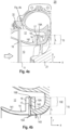
- the inlet channel 15 of the stabilizer chamber can be arranged downstream of a leading edge 24 of the compressor wheel 21, as shown in Figure 2
- the outlet opening 16 of the stabilizer chamber is typically arranged upstream of the leading edge 24 of the compressor wheel 21.
- the plurality of flow guide elements 17 are designed and arranged to provide a deflection grid through which flow can pass.
- the deflection grid can be designed and arranged to provide a deflection grid through which flow can pass essentially radially.
- substantially radial is understood to mean an angular range of ⁇ 10° or less relative to the radial direction r.
- Figure 5 For example, an inlet channel 15 inclined by an angle a is shown, which falls under the above-mentioned definition of "essentially radial".
- the Angle ⁇ is in the xr plane.
- downstream inlet channel 15 extends substantially in the radial direction, as is exemplified in the embodiments in the Figures 2 to 5 is shown.
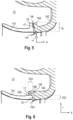
- the plurality of flow guide elements 17 are designed and arranged in such a way as to provide a deflection grid through which flow can pass substantially axially, as is shown by way of example in Figure 6
- substantially axial is understood to mean an angular range of ⁇ 45° or less, in particular ⁇ 25° or less, relative to the axial direction x.
- the axial direction x extends along the central axis 11.
- "essentially axial” is understood to mean an angular range of ⁇ 10° or less relative to the axial direction x.
- a deflection grid through which the flow can flow essentially axially can be achieved, for example, by a configuration of the inlet channel 15 of the stabilizer chamber and an arrangement of the flow guide elements 17 according to Figure 6 be provided.
- the upstream part 141 of the annular web 14 comprises a first extension 18 extending substantially in the radial direction.
- the downstream part 142 of the annular web 14 comprises a second extension 19A extending substantially in the radial direction, as shown by way of example in the Figures 4a, 4b , and 5
- the downstream part 142 of the annular web 14 comprises a second extension 19B extending substantially in the axial direction, as shown by way of example in Fig. 6 is shown.
- the stabilizer channel 10 is an integral part of a compressor housing, as shown for example in Figure 2
- the stabilizer channel 10 can be integrated into an insert 22, which can be mounted in the intake area of a compressor, as shown for example in Figure 3a
- the stabilizer channel may be part of an inner compressor housing 20A, as shown by way of example in Figure 3b in which a compressor 20 is shown with an inner compressor housing 20A and an outer compressor housing 20B.
- the upstream part 141 of the annular web 14 and the downstream part 142 of the annular web 14 are connected via the plurality of flow guide elements 17, for example by means of a screw connection.
- the screw connection can extend through the flow guide elements 17.
- the screw connections can also be designed in other ways, ie that they do not extend through the flow guide elements 17.
- other connection types such as shrinking or clamping can be used.
- the plurality of flow guide elements 17 are designed as separate components. According to an alternative embodiment, which can be combined with other embodiments described herein, the plurality of flow guide elements 17 are formed integrally (as one piece) with the upstream part 141 of the annular web 14 and/or integrally (as one piece) with the downstream part 142 of the annular web 14.
- the downstream part 142 of the annular web 14 has a centering shoulder 143.
- the upstream part 141 of the annular web 14 can have a centering shoulder (not explicitly shown).
- the centering shoulder can be cylindrical or conical.
- the plurality of flow guide elements 17 each have a centering seat that is designed to arrange the flow guide elements 17 in the inlet channel 15 circumferentially, in particular concentrically, around the central axis 11 of the main flow channel 13.
- At least one, in particular at least half or all, of the plurality of flow guide elements 17 is formed from Curtis-type blade profiles.
- at least one, in particular at least half or all of the plurality of flow guide elements 17 can be prismatic, Curtis-type blades.
- the flow guide elements 17 are designed as radial deflection blades.
- An embodiment of the flow guide elements made from Curtis-type blade profiles in particular flow guide elements in the form of prismatic Curtis-type blades, has the advantage that they can be made relatively thick, so that a better connection of the upstream part 141 of the ring web 14 with the downstream part 142 of the ring web 14 is possible via such guide elements, for example by means of screwing or other suitable types of connection.
- the plurality of flow guide elements 17 are arranged in an outflow region of the inlet channel 15 of the stabilizer chamber, as is shown by way of example in the Figures 4a and 4b
- the outflow area of the inlet channel 15 is understood to be the area of the inlet channel 15 which is located on the side of the stabilizer chamber-side outlet opening 15B.
- the outflow area can, for example, extend over half or less of the inlet channel length L.
- the outflow area 15E of the inlet channel 15 is shown in Figure 4b shown as an example.
- An arrangement of the flow guide elements 17 in an outflow region of the inlet channel 15 can have a favorable effect on flow velocities and blade vibration excitation.
- the flow guide elements 17 each have an inflow-side end 17A and an outflow-side end 17B, wherein the respective outflow-side ends 17B of the flow guide elements 17 are inclined in the circumferential direction relative to the respective inflow-side ends 17A of the flow guide elements 17, so that a swirl is reduced during flow, as is exemplified by the arrows between the inflow-side ends 17A and the outflow-side ends 17B in Figure 8 is shown.
- the respective downstream ends 17B of the flow guide elements 17 may be inclined relative to the respective upstream ends 17A of the flow guide elements 17 in the circumferential direction such that that a counter-swirl is generated, as exemplified by the arrows between the inflow ends 17A and the outflow ends 17B in Figure 7
- the direction of rotation 2 of the compressor wheel is shown in the Figures 7 and 8 The rotation of the compressor wheel results in a swirling flow.
- a compressor in particular a radial compressor or a diagonal compressor, comprising a compressor wheel 21 and a stabilizer duct 10 according to one of the embodiments described herein.
- the compressor wheel 21 comprises a number N 1 of compressor wheel blades 23 in the region of the inlet opening 15A.
- the number N 2 of guide elements in the downstream inlet duct 15 is N 2 ⁇ 1.5 ⁇ N 1 . This is advantageous for reducing noise and vibration development during operation of the compressor.
- a third aspect of the invention relates to a turbocharger with a compressor according to one of the embodiments described herein, so that advantageously a turbocharger is provided which is improved over the prior art.
Landscapes
- Engineering & Computer Science (AREA)
- Mechanical Engineering (AREA)
- General Engineering & Computer Science (AREA)
- Structures Of Non-Positive Displacement Pumps (AREA)
- Diaphragms For Electromechanical Transducers (AREA)
- Bending Of Plates, Rods, And Pipes (AREA)
- Transition And Organic Metals Composition Catalysts For Addition Polymerization (AREA)
Description
- Die Erfindung bezieht sich auf das Gebiet der Verdichter, insbesondere der Radialverdichter und Diagonalverdichter. Insbesondere betrifft die Erfindung einen Stabilisatorkanal am Verdichtereintritt zur Verbesserung der Kennfeldbreite und der Kennliniensteigung einer Verdichterstufe.
- Abgasturbolader werden zur Leistungssteigerung von Brennkraftmaschinen, insbesondere Hubkolbenmotoren, eingesetzt. Dabei besitzt ein Abgasturbolader üblicherweise einen Radial- oder Diagonalverdichter und eine Radial- oder Axialturbine.
- Der fahrbare Betriebsbereich von Radial- und Diagonalverdichtern ist hin zu kleineren Massenströmen durch die Pumpgrenze / Strömungsinstabilität limitiert: Beim Androsseln des Verdichters verschlechtern sich die Inzidenz-Winkel zunehmend, bis die Strömung ablöst und es zum Pumpen kommt. Der zulässige Inzidenz-Winkelbereich, bei welchem die Strömung noch anliegt, nimmt dabei mit steigender Strömungsmachzahl ab. Das heißt die Kennfeldbreite nimmt bei Stufen mit hohem Druckverhältnis und/oder hohem Schluckvermögen tendenziell ab.
- Als Kennlinien-Stabilisierungs-Maßnahme kann dabei über der Radkontur des Verdichterrades, parallel zum Ansaugkanal, ein Bypass in Form eines Ringhohlraumes innerhalb des Verdichtergehäuses vorgesehen werden. Ein derartiger Bypass ist auch als Stabilisatorraum oder Rezirkulator bekannt. Durch die Verwendung eines Rezirkulators kann der Massenstrom am Verdichterradeintritt in Pumpgrenznähe künstlich erhöht werden. Aus dem Verdichterrad wird ein Teil des Massenstroms in den Seitenraum (Bypass) abgezweigt. Dieser Massenstrom weist eine starke Drallkomponente auf (in Drehrichtung des Impellers - Mitdrall). Dieser Mitdrall führt dazu, dass der Arbeitsumsatz im Verdichter reduziert wird, was zu flach verlaufenden Kennlinien in Pumpgrenznähe führt.
- Flach verlaufende Kennlinien in Pumpgrenznähe können bei Anwendungen mit Druckpulsationen (z.B. bedingt durch die Ventilbewegung des aufgeladenen Verbrennungsmotors) zu unerwartetem Pumpen führen. Aus diesem Grund besteht die Anforderung einer Mindestdruckerhöhung zwischen Betriebspunkt und dem Pumpgrenzpunkt auf der Betriebsdrehzahllinie bereitzustellen. Diese Forderung kann bei Stufen mit hohem Druckverhältnis und konventionellem Bypass / Stabilisatorkanal kaum noch erfüllt werden - aufgrund des hohen Arbeitsumsatzes und des flachen Arbeitsziffer-Verlaufs über dem Massenstrom bei konstanter Drehzahl.
- Zum Stand der Technik wird auf die Druckschriften
SU 478 957 A2 EP 2 434 165 A1 , undDE 101 05 456 A1 verwiesen. Die DruckschriftSU 478 957 A2 EP 2 434 165 A1 beschreibt einen Verdichter eines Abgasturboladers, bei dem die Struktur des Einlassschlitzes, des Auslassschlitzes und des Rückführungskanals gleichzeitig gebildet werden kann, wenn das Verdichtergehäuse eines geteilten Typs zusammengebaut wird. Die DruckschriftDE 101 05 456 A1 beschreibt einen Kompressor für einen Verbrennungsmotor, der ein Kompressorgehäuse mit einer Strömungskanalstruktur und einer Rezirkulationsanordnung mit einer Bypassstruktur zur Rezirkulation eines Teils der in das Kompressorrad eintretenden Luft aufweist. - Die Aufgabe der vorliegenden Erfindung besteht darin, einen Stabilisatorkanal eines Verdichters, insbesondere eines Radialverdichters oder Diagonalverdichters, bereitzustellen, der mindestens hinsichtlich einer der aus dem Stand der Technik bekannten Nachteile verbessert ist. Des Weiteren besteht die Aufgabe der vorliegenden Erfindung darin, einen verbesserten Verdichter und einen verbesserten Turbolader bereitzustellen.
- Zur Lösung der obengenannten Aufgaben wird ein Stabilisatorkanal eines Verdichters, insbesondere eines Radialverdichters oder Diagonalverdichters, gemäß dem unabhängigen Anspruch 1 bereitgestellt. Ferner werden ein Verdichter mit einem Stabilisatorkanal gemäß den hierein beschriebenen Ausführungsformen sowie ein Turbolader mit einem derartigen Verdichter bereitgestellt.
- Weitere Aspekte, Vorteile und Merkmale der vorliegenden Erfindung sind den abhängigen Patentansprüchen, der Beschreibung und den beiliegenden Figuren zu entnehmen.
- Erfindungsgemäß wird ein Stabilisatorkanal eines Verdichters, insbesondere eines Radialverdichters oder Diagonalverdichters, gemäß Anspruch 1 bereitgestellt. Der Stabilisatorkanal umfasst einen ringförmigen Stabilisatorraum, welcher einen Hauptströmungskanal im Ansaugbereich eines Verdichterrades umgibt und durch einen Ringsteg gegenüber dem Hauptströmungskanal abgegrenzt ist. Der ringförmige Stabilisatorraum ist schaufellos und steht über einen stromabliegenden Eintrittskanal und eine stromaufliegende Austrittsöffnung in Verbindung. In dem stromabliegenden Eintrittskanal sind mehrere Strömungsleitelemente angeordnet. Der stromabliegende Eintrittskanal ist zwischen einem stromaufliegenden Teil des Ringstegs und einem stromabliegenden Teil des Ringstegs angeordnet.
- Somit wird vorteilhafterweise ein Stabilisatorkanal bereitgestellt, der eine Verbesserung der Kennfeldbreite und der Kennliniensteigung einer Verdichterstufe ermöglicht. Ferner, kann durch den erfindungsgemäßen Stabilisatorkanal mit Strömungsleitelementen im stromabliegenden Eintrittskanal ein Stabilisatorkanal bereitgestellt werden, welcher Vorteile gegenüber konventionellen aus dem Stand der Technik bekannten Stabilisatoren hinsichtlich Bauteilintegration, Containment-Eigenschaften und Herstellungskosten aufweist.
- Weiterhin wird ein Verdichter, insbesondere ein Radialverdichter oder ein Diagonalverdichter, gemäß Anspruch 14 bereitgestellt. Somit kann vorteilhafterweise ein Verdichter mit verbesserter Kennfeldbreite und Kennliniensteigung bereitgestellt werden.
- Schließlich wird ein Turbolader gemäß Anspruch 15 bereitgestellt, der gegenüber dem Stand der Technik verbessert ist.
- Im Weiteren soll die Erfindung anhand von in Figuren dargestellten Ausführungsbeispielen erläutert werden, aus denen sich weitere Vorteile und Abwandlungen ergeben. Hierbei zeigen:
- Figur 1
- eine schematische Ansicht eines Stabilisatorkanals gemäß dem Stand der Technik;
- Figur 2
- eine schematische Ansicht eines Stabilisatorkanals gemäß hierin beschriebenen Ausführungsformen;
- Figuren 3a und 3b
- schematische Ansichten eines Stabilisatorkanals gemäß weiteren hierin beschriebenen Ausführungsformen;
- Figur 4a
- eine schematische Ansicht eines Stabilisatorkanals gemäß einer weiteren hierin beschriebenen erfindungsgemäßen Ausführungsform;
- Figur 4b
- eine vergrößerte Ansicht eines Ausschnitts von
Figur 4a ; - Figuren 5 und 6
- schematische Ansichten eines Eintrittskanals eines Stabilisatorkanals gemäß weiteren hierin beschriebenen erfindungsgemäßen Ausführungsformen;
- Figur 7
- eine schematische Ansicht einer Konfiguration von Strömungsleitelementen zum Erzeugen eines Strömungsgegendralls beim Durchströmen der Leitelemente; und
- Figur 8
- eine schematische Ansicht einer Konfiguration von Strömungsleitelementen zum Abbau eines Strömungsdralls beim Durchströmen der Leitelemente
-
Figur 1 zeigt eine schematische Ansicht eines Stabilisatorkanals 10 gemäß dem Stand der Technik. Insbesondere zeigtFigur 1 einen entlang der Rotationsachse 11 des Verdichterrades 21 geführten Schnitt durch ein Gehäuse eines Radialverdichters, wie er etwa zum Verdichten von Luft in Abgasturboladern eingesetzt wird. In dem Verdichtergehäuse 5 ist ein Stabilisatorraum 12 angeordnet. Der Stabilisatorraum 12 ist über einen Eintrittskanal 15 und eine Austrittsöffnung 16 mit dem Hauptströmungskanal 13 verbunden. Der Stabilisatorraum 12 ist gegenüber dem Hauptströmungskanal 13 mittels eines Ringstegs 14 abgegrenzt. In dem Stabilisatorraum 12 sind Halterippen 121 angeordnet, die den Ringsteg 14 mit dem Verdichtergehäuse verbinden. - Mit Bezugnahme auf die
Figuren 2 bis 8 wird ein Stabilisatorkanal eines Verdichters gemäß der vorliegenden Offenbarung beschrieben. Der Verdichter kann ein Radialverdichter oder eine Diagonalverdichter sein. - Gemäß einer Ausführungsform, die mit anderen hierin beschriebenen Ausführungsformen kombiniert werden kann, umfasst der Stabilisatorkanal 10 einen ringförmigen Stabilisatorraum 12, welcher einen Hauptströmungskanal 13 im Ansaugbereich eines Verdichterrades 21 umgibt. Mit anderen Worten, typischerweise ist der Stabilisatorkanal 10 am Verdichtereintritt angeordnet. In diesem Zusammenhang sei angemerkt, dass in der vorliegenden Offenbarung unter einem "Stabilisatorkanal" insbesondere ein Kanal im Verdichtereintritt zu verstehen ist, der konfiguriert ist um eine Kennfeldbreite einer Verdichterstufe zu verbessern. Beispielsweise kann der Stabilisatorkanal 10 ein Rezirkulationskanal sein.
- Ferner ist der ringförmige Stabilisatorraum 12 durch einen Ringsteg 14 gegenüber dem Hauptströmungskanal 13 abgegrenzt, wie es beispielhaft in
Figur 2 dargestellt ist. Der ringförmige Stabilisatorraum 12 ist schaufellos. Mit anderen Worten, in dem ringförmigen Stabilisatorraum 12 sind keine Schaufeln, insbesondere keine Strömungsleitschaufeln, angeordnet. Insbesondere, kann der ringförmige Stabilisatorraum 12 auch strebenlos sein. Mit anderen Worten, der ringförmige Stabilisatorraum 12 kann schaufellos und strebenlos sein, so dass weder Strömungsleitschaufeln noch Streben in dem ringförmigen Stabilisatorraum 12 vorhanden sind. Ferner steht der ringförmige Stabilisatorraum 12 mit dem Hauptströmungskanal 13 über einen stromabliegenden Eintrittskanal 15 und eine stromaufliegende Austrittsöffnung 16 in Verbindung. Der ringförmige Stabilisatorraum 12 kann rotationssymmetrisch ausgebildet sein. - Wie schematisch in
Figur 2 dargestellt ist, sind in dem stromabliegenden Eintrittskanal 15 mehrere Strömungsleitelemente 17 angeordnet. Typischerweise sind die mehreren Strömungsleitelemente 17 umlaufend um eine zentrale Achse 11 des Hauptströmungskanals 13 angeordnet. Insbesondere können die mehreren Strömungsleitelemente 17 konzentrisch um die zentrale Achse 11 des Hauptströmungskanals 13 angeordnet sein. Ferner sei angemerkt, dass die Strömungsleitelemente 17 bündig mit der hauptströmungskanalseitigen Eintrittsöffnung 15A des Eintrittskanals 15 und/oder bündig mit der stabilisatorraumseitigen Austrittsöffnung 15B des Eintrittskanals 15 ausgeführt sein können. Alternativ können die Strömungsleitelemente 17 von der hauptströmungskanalseitigen Eintrittsöffnung 15A des Eintrittskanals 15 und/oder von der stabilisatorraumseitigen Austrittsöffnung 15B des Eintrittskanals beabstandet sein, wie es beispielhaft inFigur 2 dargestellt ist. Der stromabliegende Eintrittskanal 15 ist zwischen einem stromaufliegenden Teil 141 des Ringstegs 14 und einem stromabliegenden Teil 142 des Ringstegs 14 angeordnet. - In der vorliegenden Offenbarung ist unter dem Begriff "Eintrittskanal" ein Kanal zu verstehen, der als Strömungseintrittskanal in den Stabilisatorraum dient. Typischerweise umfasst der Eintrittskanal 15 eine hauptströmungskanalseitige Eintrittsöffnung 15A und eine stabilisatorraumseitige Austrittsöffnung 15B, wie es beispielhaft in
Figur 2 dargestellt ist. - In der vorliegenden Offenbarung beziehen sich die Begriffe "stromabliegend" und "stromaufliegend" auf die Hauptströmung im Hauptströmungskanal im Ansaugbereich eines Verdichterrades. Zum besseren Verständnis ist die Hauptströmungsrichtung 1 in den Figuren eingezeichnet. Gemäß einem Beispiel kann der Eintrittskanal 15 des Stabilisatorraums stromab zu einer Eintrittskante 24 des Verdichterrades 21 angeordnet sein, wie es in
Figur 2 gezeigt ist. Die Austrittsöffnung 16 des Stabilisatorraums ist typischerweise stromauf der Eintrittskante 24 des Verdichterrades 21 angeordnet. - Gemäß einer Ausführungsform, die mit anderen hierin beschriebenen Ausführungsformen kombiniert werden kann, sind die mehreren Strömungsleitelemente 17 derart ausgebildet und angeordnet, um ein durchströmbares Umlenkgitter bereitzustellen. Beispielsweise kann das Umlenkgitter derart ausgebildet und angeordnet sein, um ein im Wesentlichen radial durchströmbares Umlenkgitter bereitzustellen. In der vorliegenden Offenbarung ist unter dem Begriff "im Wesentlichen radial" ein Winkelbereich von α=± 45° oder geringer, insbesondere von α=± 25° oder geringer, relativ zur radialen Richtung r zu verstehen. Wie es beispielhaft in
Fig. 2 dargestellt ist erstreckt sich die radiale Richtung r senkrecht zur zentralen Achse 11. Gemäß einem Beispiel ist unter "im Wesentlichen radial" ein Winkelbereich von ±10° oder geringer relativ zur radialen Richtung r zu verstehen. Zum besseren Verständnis ist inFigur 5 beispielhaft ein um einen Winkel a geneigter Eintrittskanal 15 dargestellt, welcher unter die oben angegebene Definition von "im Wesentlichen radial" fällt. Der Winkel α befindet sich in der x-r-Ebene. - Gemäß einer Ausführungsforrn, die mit anderen hierin beschriebenen Ausführungsformen kombiniert werden kann, erstreckt sich der stromabliegende Eintrittskanal 15 im Wesentlichen in radialer Richtung, wie es beispielshaft in den Ausführungsformen in den
Figuren 2 bis 5 dargestellt ist. - Gemäß einer alternativen Ausführungsform, die mit anderen hierin beschriebenen Ausführungsformen kombiniert werden kann, sind die mehreren Strömungsleitelemente 17 derart ausgebildet und angeordnet, um ein im Wesentlichen axial durchströmbares Umlenkgitter bereitzustellen, wie es beispielhaft in
Figur 6 gezeigt ist. In der vorliegenden Offenbarung ist unter dem Begriff "im Wesentlichen axial" ein Winkelbereich von ± 45° oder geringer, insbesondere ± 25° oder geringer, relativ zur axialen Richtung x zu verstehen. Wie beispielhaft inFig. 2 dargestellt ist erstreckt sich die axiale Richtung x entlang der zentralen Achse 11. Gemäß einem Beispiel ist unter "im Wesentlichen axial" ein Winkelbereich von ±10° oder geringer relativ zur axialen Richtung x zu verstehen. Ein im Wesentlichen axial durchströmbares Umlenkgitter kann beispielsweise durch eine Konfiguration des Eintrittskanals 15 des Stabilisatorraums und eine Anordnung der Strömungsleitelemente 17 gemäßFigur 6 bereitgestellt werden. - Gemäß einer Ausführungsform, die mit anderen hierin beschriebenen Ausführungsformen kombiniert werden kann, umfasst der stromabliegende Eintrittskanal 15 einen sich im Wesentlichen radial erstreckenden Teil 15C und einen sich im Wesentlichen axial erstreckenden Teil 15D, wie es beispielhaft in
Figur 6 dargestellt ist. Zwischen dem sich im Wesentlichen radial erstreckenden Teil 15C und dem sich im Wesentlichen in axial erstreckenden Teil 15D befindet sich typischer Weise ein gekrümmter Übergangsbereich 15F. - Erfindungsgemäß umfasst der stromaufliegende Teil 141 des Ringstegs 14 einen sich im Wesentlichen in radialer Richtung erstreckenden ersten Fortsatz 18. Der stromabliegende Teil 142 des Ringstegs 14 umfasst einen sich im Wesentlichen in radialer Richtung erstreckenden zweiten Fortsatz 19A, wie es beispielhaft in den
Figuren 4a, 4b , und5 dargestellt ist. Alternativ umfasst der stromabliegende Teil 142 des Ringstegs 14 einen sich im Wesentlichen in axialer Richtung erstreckenden zweiten Fortsatz 19B, wie es beispielhaft inFig. 6 dargestellt ist. - Gemäß einer Ausführungsform, die mit anderen hierin beschriebenen Ausführungsformen kombiniert werden kann, ist der Stabilisatorkanal 10 integraler Bestandteil eines Verdichtergehäuses, wie es beispielhaft in
Figur 2 dargestellt ist. Alternativ kann der Stabilisatorkanal 10 in ein Einsatzteil 22 integriert sein, welches im Ansaugbereich eines Verdichters montierbar ist, wie es beispielhaft inFigur 3a dargestellt ist. Gemäß einem weiteren Beispiel kann der Stabilisatorkanal Bestandteil eines inneren Verdichtergehäuses 20A sein, wie es beispielhaft inFigur 3b dargestellt ist, in welcher ein Verdichter 20 mit einem inneren Verdichtergehäuse 20A und einem äußeren Verdichtergehäuse 20B gezeigt ist. - Gemäß einer Ausführungsform, die mit anderen hierin beschriebenen Ausführungsformen kombiniert werden kann, ist der stromaufliegende Teil 141 des Ringstegs 14 und der stromabliegende Teil 142 des Ringstegs 14 über die mehreren Strömungsleitelemente 17 verbunden, beispielsweise mittels einer Verschraubung. Die Verschraubung kann sich durch die Strömungsleitelemente 17 erstrecken. Es sei angemerkt, dass die Verschraubungen auch auf andere Weise ausgeführt werden können, d.h. so dass sie sich nicht durch die Strömungsleitelemente 17 erstecken. Alternativ oder zusätzlich können auch andere Verbindungsarten wie zum Beispiel Schrumpfen oder Klemmen verwendet werden.
- Gemäß einer Ausführungsform, die mit anderen hierin beschriebenen Ausführungsformen kombiniert werden kann, sind die mehreren Strömungsleitelemente 17 als separate Bauteile ausgeführt. Gemäß einer alternativen Ausführungsform, die mit anderen hierin beschriebenen Ausführungsformen kombiniert werden kann, sind die mehreren Strömungsleitelemente 17 integral (einteilig) mit dem stromaufliegenden Teil 141 des Ringstegs 14 und/oder integral (einteilig) mit dem stromabliegenden Teil 142 des Ringstegs 14 ausgebildet.
- Gemäß einer Ausführungsform, die mit anderen hierin beschriebenen Ausführungsformen kombiniert werden kann, weist der stromabliegende Teil 142 des Ringstegs 14 einen Zentrierabsatz 143 auf. Alternativ oder zusätzlich kann der stromaufliegende Teil 141 des Ringstegs 14 einen Zentrierabsatz aufweisen (nicht explizit dargestellt). Der Zentrierabsatz kann zylindrisch oder konisch ausgeführt sein.
- Gemäß einer Ausführungsform, die mit anderen hierin beschriebenen Ausführungsformen kombiniert werden kann, weisen die mehreren Strömungsleitelemente 17 jeweils einen Zentriersitz auf, der ausgebildet ist, um die Strömungsleitelemente 17 in dem Eintrittskanal 15 umlaufend, insbesondere konzentrisch, um die zentrale Achse 11 des Hauptströmungskanals 13 anzuordnen.
- Gemäß einer Ausführungsform, die mit anderen hierin beschriebenen Ausführungsformen kombiniert werden kann, ist mindestens eines, insbesondere mindestens die Hälfte oder alle, der mehreren Strömungsleitelemente 17 aus Curtis-artigen Schaufelprofilen gebildet. Insbesondere kann mindestens eines, insbesondere mindestens die Hälfte oder alle der mehreren Strömungsleitelemente 17 prismatische, Curtis-artige Schaufeln sein. Typischerweise, sind die Strömungsleitelemente 17 als radiale Umlenkschaufeln ausgebildet. Eine Ausführung der Strömungsleitelemente aus Curtis-artigen Schaufelprofilen, insbesondere Strömungsleitelemente in Form von prismatischen Curtis-artigen Schaufeln, hat den Vorteil, dass diese relativ dick ausgeführt werden können, so dass eine bessere Verbindung des stromaufliegenden Teil 141 des Ringstegs 14 mit dem stromabliegenden Teil 142 des Ringstegs 14 über derartige Leitelemente ermöglicht wird, beispielsweise mittels Verschraubung oder anderen geeigneten Verbindungsarten.
- Gemäß einer Ausführungsform, die mit anderen hierin beschriebenen Ausführungsformen kombiniert werden kann, sind die mehreren Strömungsleitelemente 17 in einem Ausströmbereich des Eintrittskanals 15 des Stabilisatorraums angeordnet, wie es beispielhaft in den
Figuren 4a und 4b dargestellt ist. Unter dem Ausströmbereich des Eintrittskanals 15 ist der Bereich des Eintrittskanals 15 zu verstehen, welcher sich auf der Seite der stabilisatorraumseitigen Austrittsöffnung 15B befindet. Der Ausströmbereich kann sich beispielsweise über die Hälfte oder weniger der Eintrittskanallänge L erstrecken. Zum besseren Verständnis ist der Ausströmbereich 15E des Eintrittskanals 15 inFigur 4b beispielhaft dargestellt. Eine Anordnung der Strömungsleitelemente 17 in einem Ausströmbereich des Eintrittskanals 15 kann sich günstig auf Strömungsgeschwindigkeiten und Schaufelschwingungsanregung auswirken. - Gemäß einer Ausführungsform, die mit anderen hierin beschriebenen Ausführungsformen kombiniert werden kann, weisen die Strömungsleitelemente 17 jeweils ein einströmseitiges Ende 17A und ein abströmseitiges Ende 17B auf, wobei die jeweiligen abströmseitigen Enden 17B der Strömungsleitelemente 17 relativ zu den jeweiligen einströmseitigen Enden 17A der Strömungsleitelemente 17 in Umfangsrichtung geneigt sind, so dass beim Durchströmen ein Drall abgebaut wird, wie es beispielhaft durch die Pfeile zwischen den einströmseitigen Enden 17A und den abströmseitigen Enden 17B in
Figur 8 dargestellt ist. - Alternativ können die jeweiligen abströmseitigen Enden 17B der Strömungsleitelemente 17 relativ zu den jeweiligen einströmseitigen Enden 17A der Strömungsleitelemente 17 in Umfangsrichtung derart geneigt sein, dass ein Gegendrall erzeugt wird, wie es beispielhaft durch die Pfeile zwischen den einströmseitigen Enden 17A und den abströmseitigen Enden 17B in
Figur 7 dargestellt ist. Zum besseren Verständnis ist die Rotationsrichtung 2 des Verdichterrades in denFiguren 7 und 8 dargestellt. Die Rotation des Verdichterrades führt zu einer mit Drall beaufschlagten Strömung. - Gemäß einem zweiten Aspekt der vorliegenden Offenbarung wird ein Verdichter, insbesondere ein Radialverdichter oder ein Diagonalverdichter, bereitgestellt der ein Verdichterrad 21 und einen Stabilisatorkanal 10 gemäß einer der hierein beschriebenen Ausführungsformen umfasst. Gemäß einer Ausführungsform, die mit anderen hierin beschriebenen Ausführungsformen kombiniert werden kann, umfasst das Verdichterrad 21 im Bereich der Eintrittsöffnung 15A eine Anzahl N1 an Verdichterradschaufeln 23. Eine Anzahl N2 der Leitelemente in dem stromabliegenden Eintrittskanal 15 ist N2 ≥ 1.5×N1. Dies ist vorteilhaft um die Geräusch- und Schwingungsentwicklung im Betrieb des Verdichters zu reduzieren.
- Ein dritter Aspekt der Erfindung betrifft einen Turbolader mit einem Verdichter gemäß einer der hierein beschriebenen Ausführungsformen, so dass vorteilhafterweise ein Turbolader bereitgestellt wird der gegenüber dem Stand der Technik verbessert ist.
-
- 1
- Hauptströmungsrichtung
- 2
- Rotationsrichtung des Verdichterrades
- 5
- Verdichtergehäuse
- 10
- Stabilisatorkanal
- 11
- zentrale Achse / Rotationsachse des Verdichterrades
- 12
- ringförmiger Stabilisatorraum
- 121
- Strebe
- 13
- Hauptströmungskanal
- 14
- Ringsteg
- 141
- stromaufliegender Teil des Ringstegs
- 142
- stromabliegender Teil des Ringstegs
- 143
- Zentrierabsatz
- 15
- Eintrittskanal des Stabilisatorraums
- 15A
- hauptströmungskanalseitige Eintrittsöffnung des Eintrittskanals
- 15B
- stabilisatorraumseitige Austrittsöffnung des Eintrittskanals
- 15C
- im Wesentlichen radial erstreckender Teil des Eintrittskanals
- 15D
- im Wesentlichen axial erstreckender Teil des Eintrittskanals
- 15E
- Ausströmbereich des Eintrittskanals
- 15F
- Übergangsbereich
- 16
- Austrittsöffnung des Stabilisatorraums
- 17
- Strömungsleitelemente
- 17A
- einströmseitiges Ende der Strömungsleitelemente
- 17B
- ausströmseitiges Ende der Strömungsleitelemente
- 18
- im Wesentlichen in radialer Richtung erstreckender erster Fortsatz
- 19A
- im Wesentlichen in radialer Richtung erstreckender zweiter Fortsatz
- 19B
- im Wesentlichen in axialer Richtung erstreckender zweiter Fortsatz
- 20
- Verdichter
- 20A
- Inneres Verdichtergehäuse
- 20B
- Äußeres Verdichtergehäuse
- 21
- Verdichterrad
- 22
- Einsatzteil
- 23
- Verdichterradschaufeln
- 24
- Eintrittskante des Verdichterrades
- r
- radiale Richtung
- x
- axiale Richtung
- L
- Länge des Eintrittskanals
- α
- Winkel in der x-r-Ebene zur Erläuterung "im Wesentlichen radial"
Claims (15)
- Stabilisatorkanal (10) eines Verdichters, insbesondere eines Radialverdichters oder Diagonalverdichters, mit einem ringförmigen Stabilisatorraum (12), welcher einen Hauptströmungskanal (13) im Ansaugbereich eines Verdichterrades (21) umgibt und durch einen Ringsteg (14) gegenüber dem Hauptströmungskanal (13) abgegrenzt ist, wobei der ringförmige Stabilisatorraum (12) schaufellos ist und über einen stromabliegenden Eintrittskanal (15) und eine stromaufliegende Austrittsöffnung (16) in Verbindung steht, wobei in dem stromabliegenden Eintrittskanal (15) mehrere Strömungsleitelemente (17) angeordnet sind, und wobei der stromabliegende Eintrittskanal (15) zwischen einem stromaufliegenden Teil (141) des Ringstegs (14) und einem stromabliegenden Teil (142) des Ringstegs (14) angeordnet ist, dadurch gekennzeichnet, dass derstromaufliegende Teil (141) des Ringstegs (14) einen sich im Wesentlichen in radialer Richtung erstreckenden ersten Fortsatz (18) undder stromabliegende Teil (142) des Ringstegs (14) einen sich im Wesentlichen in radialer Richtung erstreckenden zweiten Fortsatz (19A) umfassen, oder dassder stromabliegende Teil (142) des Ringstegs (14) einen sich im Wesentlichen in axialer Richtung erstreckenden zweiten Fortsatz (19B) umfasst.
- Stabilisatorkanal nach Anspruch 1, wobei die mehreren Strömungsleitelemente (17) ausgebildet und angeordnet sind, um ein durchströmbares Umlenkgitter, insbesondere ein im Wesentlichen radial durchströmbares Umlenkgitter oder ein im Wesentlichen axial durchströmbares Umlenkgitter, bereitzustellen.
- Stabilisatorkanal nach Anspruch 1 oder 2, wobei sich der stromabliegende Eintrittskanal (15) im Wesentlichen in radialer Richtung erstreckt, oder wobei der stromabliegende Eintrittskanal (15) einen sich im Wesentlichen radial erstreckenden Teil (15C) und einen sich im Wesentlichen axial erstreckenden Teil (15D) umfasst.
- Stabilisatorkanal nach einem der Ansprüche 1 bis 3, wobei die mehreren Strömungsleitelemente (17) umlaufend, insbesondere konzentrisch, um eine zentrale Achse (11) des Hauptströmungskanals (13) angeordnet sind.
- Stabilisatorkanal nach einem der Ansprüche 1 bis 4, wobei der Stabilisatorkanal integraler Bestandteil eines Verdichtergehäuses ist, oder wobei der Stabilisatorkanal in ein Einsatzteil (22) integriert ist, welches im Ansaugbereich eines Verdichters montierbar ist, oder wobei der Stabilisatorkanal Bestandteil eines inneren Verdichtergehäuses (20A) ist.
- Stabilisatorkanal nach einem der Ansprüche 1 bis 5, wobei der stromaufliegende Teil (141) des Ringstegs (14) und der stromabliegende Teil (142) des Ringstegs (14) über die mehreren Strömungsleitelemente (17) verbunden, insbesondere verschraubt, sind.
- Stabilisatorkanal nach einem der Ansprüche 1 bis 6, wobei die mehreren Strömungsleitelemente (17) als separate Bauteile ausgeführt sind.
- Stabilisatorkanal nach einem der Ansprüche 1 bis 6, wobei die mehreren Strömungsleitelemente (17) integral mit dem stromaufliegenden Teil (141) des Ringstegs (14) und/oder integral mit dem stromabliegenden Teil (142) des Ringstegs (14) ausgebildet sind.
- Stabilisatorkanal nach einem der Ansprüche 1 bis 8, wobei der stromabliegende Teil (142) des Ringstegs (14) und/oder der stromaufliegende Teil (141) des Ringstegs (14) einen Zentrierabsatz (143), insbesondere einen zylindrischen oder konischen Zentrierabsatz, aufweisen.
- Stabilisatorkanal nach einem der Ansprüche 1 bis 9, wobei die mehreren Strömungsleitelemente (17) jeweils einen Zentriersitz aufweisen, der ausgebildet ist, um die Strömungsleitelemente (17) in dem Eintrittskanal (15) umlaufend, insbesondere konzentrisch, um die zentrale Achse (11) des Hauptströmungskanals (13) anzuordnen.
- Stabilisatorkanal nach einem der Ansprüche 1 bis 10, wobei mindestens eines, insbesondere mindestens die Hälfte oder alle der mehreren Strömungsleitelemente (17) aus Curtis-artigen Schaufelprofilen gebildet sind, insbesondere wobei mindestens eines, insbesondere mindestens die Hälfte oder alle der mehreren Strömungsleitelemente (17) prismatische, Curtis-artige Schaufeln sind.
- Stabilisatorkanal nach einem der Ansprüche 1 bis 11, wobei die mehrere Strömungsleitelemente (17) in einem Ausströmbereich (15E) des Eintrittskanals (15) des Stabilisatorraums angeordnet sind.
- Stabilisatorkanal nach einem der Ansprüche 1 bis 12, wobei die Strömungsleitelemente (17) jeweils ein einströmseitiges Ende (17A) und ein abströmseitiges Ende (17B) aufweisen, wobei die abströmseitigen Enden der Strömungsleitelemente (17) relativ zu den einströmseitigen Enden (17A) der Strömungsleitelemente (17) in Umfangsrichtung geneigt sind, so dass beim Durchströmen ein Drall abgebaut wird oder ein Gegendrall erzeugt wird.
- Verdichter (20), insbesondere Radialverdichter oder Diagonalverdichter, mit einem Verdichterrad (21) und einem Stabilisatorkanal (10) gemäß einem der Ansprüche 1 bis 13, insbesondere wobei das Verdichterrad (21) im Bereich der Eintrittsöffnung (15A) des Eintrittskanals (15) eine Anzahl N1 an Verdichterradschaufeln (23) umfasst und eine Anzahl N2 der Leitelemente N2≥ 1.5×N1 ist.
- Turbolader mit einem Verdichter (20) nach Anspruch 14.
Applications Claiming Priority (2)
| Application Number | Priority Date | Filing Date | Title |
|---|---|---|---|
| EP20156161.0A EP3862573A1 (de) | 2020-02-07 | 2020-02-07 | Stabilisatorkanal eines verdichters |
| PCT/EP2021/052430 WO2021156251A1 (de) | 2020-02-07 | 2021-02-02 | Stabilisatorkanal eines verdichters |
Publications (2)
| Publication Number | Publication Date |
|---|---|
| EP4100653A1 EP4100653A1 (de) | 2022-12-14 |
| EP4100653B1 true EP4100653B1 (de) | 2025-04-02 |
Family
ID=69528597
Family Applications (2)
| Application Number | Title | Priority Date | Filing Date |
|---|---|---|---|
| EP20156161.0A Withdrawn EP3862573A1 (de) | 2020-02-07 | 2020-02-07 | Stabilisatorkanal eines verdichters |
| EP21702274.8A Active EP4100653B1 (de) | 2020-02-07 | 2021-02-02 | Stabilisatorkanal eines verdichters |
Family Applications Before (1)
| Application Number | Title | Priority Date | Filing Date |
|---|---|---|---|
| EP20156161.0A Withdrawn EP3862573A1 (de) | 2020-02-07 | 2020-02-07 | Stabilisatorkanal eines verdichters |
Country Status (7)
| Country | Link |
|---|---|
| US (1) | US11953022B2 (de) |
| EP (2) | EP3862573A1 (de) |
| JP (1) | JP7633264B2 (de) |
| KR (1) | KR102942015B1 (de) |
| CN (1) | CN115066559B (de) |
| FI (1) | FI4100653T3 (de) |
| WO (1) | WO2021156251A1 (de) |
Families Citing this family (1)
| Publication number | Priority date | Publication date | Assignee | Title |
|---|---|---|---|---|
| EP3916241A1 (de) * | 2020-05-25 | 2021-12-01 | ABB Schweiz AG | Stabilisator eines verdichters |
Family Cites Families (22)
| Publication number | Priority date | Publication date | Assignee | Title |
|---|---|---|---|---|
| SU478957A2 (ru) * | 1973-10-05 | 1975-07-30 | Предприятие П/Я В-2504 | Центробежный компрессор |
| CN1070721A (zh) * | 1991-09-19 | 1993-04-07 | 库恩尔·科普和科什有限公司 | 压缩机工况区域稳定装置 |
| JP2000064848A (ja) | 1998-08-21 | 2000-02-29 | Ishikawajima Harima Heavy Ind Co Ltd | ターボチャージャ |
| DE10105456A1 (de) | 2001-02-07 | 2002-08-08 | Daimler Chrysler Ag | Verdichter, insbesondere für eine Brennkraftmaschine |
| JP4321037B2 (ja) * | 2002-10-25 | 2009-08-26 | 株式会社豊田中央研究所 | ターボチャージャ用遠心圧縮機 |
| DE602004001908T2 (de) * | 2003-04-30 | 2007-04-26 | Holset Engineering Co. Ltd., Huddersfield | Kompressor |
| DE102004032978A1 (de) * | 2004-07-08 | 2006-02-09 | Mtu Aero Engines Gmbh | Strömungsstruktur für einen Turboverdichter |
| JP2006342682A (ja) * | 2005-06-07 | 2006-12-21 | Ishikawajima Harima Heavy Ind Co Ltd | 遠心圧縮機の作動域拡大方法及び装置 |
| JP2007127108A (ja) * | 2005-11-07 | 2007-05-24 | Mitsubishi Heavy Ind Ltd | 排気ターボ過給機のコンプレッサ |
| BE1017069A3 (nl) * | 2006-04-25 | 2008-01-08 | Atlas Copco Airpower Nv | Verbeterde turbocompressor met leischoepen. |
| JP5088610B2 (ja) | 2007-06-18 | 2012-12-05 | 株式会社Ihi | 遠心圧縮機ケーシング |
| JP2009264276A (ja) * | 2008-04-25 | 2009-11-12 | Mitsubishi Heavy Ind Ltd | 圧縮機 |
| DE102008026744A1 (de) * | 2008-06-04 | 2009-01-22 | Daimler Ag | Verdichter, insbesondere für einen Abgasturbolader einer Brennkraftmaschine |
| JP5479021B2 (ja) * | 2009-10-16 | 2014-04-23 | 三菱重工業株式会社 | 排気ターボ過給機のコンプレッサ |
| DE102012200866A1 (de) * | 2012-01-23 | 2013-07-25 | Bayerische Motoren Werke Aktiengesellschaft | Verdichter für die Aufladung einer Brennkraftmaschine |
| US9303561B2 (en) * | 2012-06-20 | 2016-04-05 | Ford Global Technologies, Llc | Turbocharger compressor noise reduction system and method |
| CN105358837B (zh) | 2013-07-04 | 2018-03-20 | 三菱重工业株式会社 | 离心压缩机 |
| JP6388772B2 (ja) | 2014-02-25 | 2018-09-12 | 三菱重工業株式会社 | 遠心圧縮機およびディフューザ製造方法 |
| JP6504273B2 (ja) * | 2016-02-12 | 2019-04-24 | 株式会社Ihi | 遠心圧縮機 |
| DE102018102704A1 (de) * | 2018-02-07 | 2019-08-08 | Man Energy Solutions Se | Radialverdichter |
| DE102018222289B3 (de) * | 2018-12-19 | 2019-12-24 | Continental Automotive Gmbh | Radialverdichter mit Kennfeldstabilisierung für eine Aufladevorrichtung einer Brennkraftmaschine und Aufladevorrichtung |
| JP7220097B2 (ja) * | 2019-02-27 | 2023-02-09 | 三菱重工業株式会社 | 遠心圧縮機及びターボチャージャ |
-
2020
- 2020-02-07 EP EP20156161.0A patent/EP3862573A1/de not_active Withdrawn
-
2021
- 2021-02-02 FI FIEP21702274.8T patent/FI4100653T3/fi active
- 2021-02-02 WO PCT/EP2021/052430 patent/WO2021156251A1/de not_active Ceased
- 2021-02-02 JP JP2022547908A patent/JP7633264B2/ja active Active
- 2021-02-02 US US17/797,908 patent/US11953022B2/en active Active
- 2021-02-02 CN CN202180012806.0A patent/CN115066559B/zh active Active
- 2021-02-02 KR KR1020227030283A patent/KR102942015B1/ko active Active
- 2021-02-02 EP EP21702274.8A patent/EP4100653B1/de active Active
Also Published As
| Publication number | Publication date |
|---|---|
| WO2021156251A1 (de) | 2021-08-12 |
| CN115066559A (zh) | 2022-09-16 |
| JP2023513198A (ja) | 2023-03-30 |
| US11953022B2 (en) | 2024-04-09 |
| CN115066559B (zh) | 2025-04-29 |
| US20230071034A1 (en) | 2023-03-09 |
| KR20220131332A (ko) | 2022-09-27 |
| FI4100653T3 (fi) | 2025-06-12 |
| EP4100653A1 (de) | 2022-12-14 |
| JP7633264B2 (ja) | 2025-02-19 |
| EP3862573A1 (de) | 2021-08-11 |
| KR102942015B1 (ko) | 2026-03-20 |
Similar Documents
| Publication | Publication Date | Title |
|---|---|---|
| DE112015001237B4 (de) | Abgasturbolader | |
| EP1488084B1 (de) | Variabler abgasturbolader | |
| EP2024644A1 (de) | Diffusor | |
| WO2007093367A1 (de) | Verdichter für eine brennkraftmaschine | |
| DE102005019896B4 (de) | Drallerzeugungseinrichtung | |
| WO2019063384A1 (de) | Diffusor für einen verdichter | |
| WO2009086959A1 (de) | Leitschaufel für eine variable turbinengeometrie | |
| DE102015219556A1 (de) | Diffusor für Radialverdichter, Radialverdichter und Turbomaschine mit Radialverdichter | |
| EP3682092B1 (de) | Abgasturbine mit diffusor | |
| EP1621733A2 (de) | Strömungsstruktur für eine Gasturbine | |
| EP2054595B1 (de) | Verdichtergehäuse | |
| EP4100653B1 (de) | Stabilisatorkanal eines verdichters | |
| EP3698021B1 (de) | Diffusoranordnung einer abgasturbine | |
| EP4158205B1 (de) | Stabilisator eines verdichters | |
| WO2021239455A1 (de) | Stabilisatorkanal eines verdichters | |
| DE102008060943B4 (de) | Mehrflutiges Turbinengehäuse | |
| DE112020007258T5 (de) | Laufrad eines zentrifugalverdichters und zentrifugalverdichter | |
| DE102018212756B3 (de) | Radialverdichter, Aufladevorrichtung und Brennkraftmaschine mit Abgasrückführeinrichtung | |
| DE112019006767T5 (de) | Zentrifugalkompressor und turbolader | |
| DE202021104007U1 (de) | Strahltriebwerk und Strahltriebwerksanordnung | |
| DE10351447A1 (de) | Abgasturbolader für eine Brennkraftmaschine | |
| DE112019006771T5 (de) | Zentrifugalkompressor und turbolader | |
| DE102018221161B4 (de) | Abgasturbine eines Abgasturboladers sowie Abgasturbolader mit einem strömungstechnischen Störelement im Turbinengehäuse | |
| DE102016213626A1 (de) | Turbine für einen Abgasturbolader | |
| DE102024116479A1 (de) | Leitschaufelelement für einen Verdichter einer Strömungsmaschine, Leitschaufelcluster und Strömungsmaschine |
Legal Events
| Date | Code | Title | Description |
|---|---|---|---|
| STAA | Information on the status of an ep patent application or granted ep patent |
Free format text: STATUS: UNKNOWN |
|
| STAA | Information on the status of an ep patent application or granted ep patent |
Free format text: STATUS: THE INTERNATIONAL PUBLICATION HAS BEEN MADE |
|
| PUAI | Public reference made under article 153(3) epc to a published international application that has entered the european phase |
Free format text: ORIGINAL CODE: 0009012 |
|
| STAA | Information on the status of an ep patent application or granted ep patent |
Free format text: STATUS: REQUEST FOR EXAMINATION WAS MADE |
|
| 17P | Request for examination filed |
Effective date: 20220712 |
|
| AK | Designated contracting states |
Kind code of ref document: A1 Designated state(s): AL AT BE BG CH CY CZ DE DK EE ES FI FR GB GR HR HU IE IS IT LI LT LU LV MC MK MT NL NO PL PT RO RS SE SI SK SM TR |
|
| DAV | Request for validation of the european patent (deleted) | ||
| DAX | Request for extension of the european patent (deleted) | ||
| GRAP | Despatch of communication of intention to grant a patent |
Free format text: ORIGINAL CODE: EPIDOSNIGR1 |
|
| STAA | Information on the status of an ep patent application or granted ep patent |
Free format text: STATUS: GRANT OF PATENT IS INTENDED |
|
| INTG | Intention to grant announced |
Effective date: 20240826 |
|
| GRAJ | Information related to disapproval of communication of intention to grant by the applicant or resumption of examination proceedings by the epo deleted |
Free format text: ORIGINAL CODE: EPIDOSDIGR1 |
|
| STAA | Information on the status of an ep patent application or granted ep patent |
Free format text: STATUS: REQUEST FOR EXAMINATION WAS MADE |
|
| GRAP | Despatch of communication of intention to grant a patent |
Free format text: ORIGINAL CODE: EPIDOSNIGR1 |
|
| STAA | Information on the status of an ep patent application or granted ep patent |
Free format text: STATUS: GRANT OF PATENT IS INTENDED |
|
| RAP3 | Party data changed (applicant data changed or rights of an application transferred) |
Owner name: ACCELLERON SWITZERLAND LTD. |
|
| INTC | Intention to grant announced (deleted) | ||
| INTG | Intention to grant announced |
Effective date: 20241204 |
|
| GRAS | Grant fee paid |
Free format text: ORIGINAL CODE: EPIDOSNIGR3 |
|
| GRAA | (expected) grant |
Free format text: ORIGINAL CODE: 0009210 |
|
| STAA | Information on the status of an ep patent application or granted ep patent |
Free format text: STATUS: THE PATENT HAS BEEN GRANTED |
|
| AK | Designated contracting states |
Kind code of ref document: B1 Designated state(s): AL AT BE BG CH CY CZ DE DK EE ES FI FR GB GR HR HU IE IS IT LI LT LU LV MC MK MT NL NO PL PT RO RS SE SI SK SM TR |
|
| REG | Reference to a national code |
Ref country code: GB Ref legal event code: FG4D Free format text: NOT ENGLISH |
|
| REG | Reference to a national code |
Ref country code: CH Ref legal event code: EP |
|
| REG | Reference to a national code |
Ref country code: IE Ref legal event code: FG4D Free format text: LANGUAGE OF EP DOCUMENT: GERMAN |
|
| REG | Reference to a national code |
Ref country code: DE Ref legal event code: R096 Ref document number: 502021007089 Country of ref document: DE |
|
| REG | Reference to a national code |
Ref country code: FI Ref legal event code: FGE |
|
| REG | Reference to a national code |
Ref country code: NL Ref legal event code: MP Effective date: 20250402 |
|
| PG25 | Lapsed in a contracting state [announced via postgrant information from national office to epo] |
Ref country code: NL Free format text: LAPSE BECAUSE OF FAILURE TO SUBMIT A TRANSLATION OF THE DESCRIPTION OR TO PAY THE FEE WITHIN THE PRESCRIBED TIME-LIMIT Effective date: 20250402 |
|
| PG25 | Lapsed in a contracting state [announced via postgrant information from national office to epo] |
Ref country code: PT Free format text: LAPSE BECAUSE OF FAILURE TO SUBMIT A TRANSLATION OF THE DESCRIPTION OR TO PAY THE FEE WITHIN THE PRESCRIBED TIME-LIMIT Effective date: 20250804 Ref country code: ES Free format text: LAPSE BECAUSE OF FAILURE TO SUBMIT A TRANSLATION OF THE DESCRIPTION OR TO PAY THE FEE WITHIN THE PRESCRIBED TIME-LIMIT Effective date: 20250402 |
|
| REG | Reference to a national code |
Ref country code: LT Ref legal event code: MG9D |
|
| PG25 | Lapsed in a contracting state [announced via postgrant information from national office to epo] |
Ref country code: GR Free format text: LAPSE BECAUSE OF FAILURE TO SUBMIT A TRANSLATION OF THE DESCRIPTION OR TO PAY THE FEE WITHIN THE PRESCRIBED TIME-LIMIT Effective date: 20250703 Ref country code: NO Free format text: LAPSE BECAUSE OF FAILURE TO SUBMIT A TRANSLATION OF THE DESCRIPTION OR TO PAY THE FEE WITHIN THE PRESCRIBED TIME-LIMIT Effective date: 20250702 |
|
| PG25 | Lapsed in a contracting state [announced via postgrant information from national office to epo] |
Ref country code: PL Free format text: LAPSE BECAUSE OF FAILURE TO SUBMIT A TRANSLATION OF THE DESCRIPTION OR TO PAY THE FEE WITHIN THE PRESCRIBED TIME-LIMIT Effective date: 20250402 |
|
| PG25 | Lapsed in a contracting state [announced via postgrant information from national office to epo] |
Ref country code: BG Free format text: LAPSE BECAUSE OF FAILURE TO SUBMIT A TRANSLATION OF THE DESCRIPTION OR TO PAY THE FEE WITHIN THE PRESCRIBED TIME-LIMIT Effective date: 20250402 |
|
| PG25 | Lapsed in a contracting state [announced via postgrant information from national office to epo] |
Ref country code: HR Free format text: LAPSE BECAUSE OF FAILURE TO SUBMIT A TRANSLATION OF THE DESCRIPTION OR TO PAY THE FEE WITHIN THE PRESCRIBED TIME-LIMIT Effective date: 20250402 |
|
| PG25 | Lapsed in a contracting state [announced via postgrant information from national office to epo] |
Ref country code: RS Free format text: LAPSE BECAUSE OF FAILURE TO SUBMIT A TRANSLATION OF THE DESCRIPTION OR TO PAY THE FEE WITHIN THE PRESCRIBED TIME-LIMIT Effective date: 20250702 |
|
| PG25 | Lapsed in a contracting state [announced via postgrant information from national office to epo] |
Ref country code: IS Free format text: LAPSE BECAUSE OF FAILURE TO SUBMIT A TRANSLATION OF THE DESCRIPTION OR TO PAY THE FEE WITHIN THE PRESCRIBED TIME-LIMIT Effective date: 20250802 |
|
| PG25 | Lapsed in a contracting state [announced via postgrant information from national office to epo] |
Ref country code: LV Free format text: LAPSE BECAUSE OF FAILURE TO SUBMIT A TRANSLATION OF THE DESCRIPTION OR TO PAY THE FEE WITHIN THE PRESCRIBED TIME-LIMIT Effective date: 20250402 |
|
| REG | Reference to a national code |
Ref country code: DE Ref legal event code: R097 Ref document number: 502021007089 Country of ref document: DE |
|
| PG25 | Lapsed in a contracting state [announced via postgrant information from national office to epo] |
Ref country code: DK Free format text: LAPSE BECAUSE OF FAILURE TO SUBMIT A TRANSLATION OF THE DESCRIPTION OR TO PAY THE FEE WITHIN THE PRESCRIBED TIME-LIMIT Effective date: 20250402 Ref country code: SM Free format text: LAPSE BECAUSE OF FAILURE TO SUBMIT A TRANSLATION OF THE DESCRIPTION OR TO PAY THE FEE WITHIN THE PRESCRIBED TIME-LIMIT Effective date: 20250402 |
|
| PG25 | Lapsed in a contracting state [announced via postgrant information from national office to epo] |
Ref country code: EE Free format text: LAPSE BECAUSE OF FAILURE TO SUBMIT A TRANSLATION OF THE DESCRIPTION OR TO PAY THE FEE WITHIN THE PRESCRIBED TIME-LIMIT Effective date: 20250402 |
|
| PG25 | Lapsed in a contracting state [announced via postgrant information from national office to epo] |
Ref country code: SK Free format text: LAPSE BECAUSE OF FAILURE TO SUBMIT A TRANSLATION OF THE DESCRIPTION OR TO PAY THE FEE WITHIN THE PRESCRIBED TIME-LIMIT Effective date: 20250402 |
|
| PG25 | Lapsed in a contracting state [announced via postgrant information from national office to epo] |
Ref country code: IT Free format text: LAPSE BECAUSE OF FAILURE TO SUBMIT A TRANSLATION OF THE DESCRIPTION OR TO PAY THE FEE WITHIN THE PRESCRIBED TIME-LIMIT Effective date: 20250402 |
|
| PLBE | No opposition filed within time limit |
Free format text: ORIGINAL CODE: 0009261 |
|
| STAA | Information on the status of an ep patent application or granted ep patent |
Free format text: STATUS: NO OPPOSITION FILED WITHIN TIME LIMIT |
|
| REG | Reference to a national code |
Ref country code: CH Ref legal event code: L10 Free format text: ST27 STATUS EVENT CODE: U-0-0-L10-L00 (AS PROVIDED BY THE NATIONAL OFFICE) Effective date: 20260211 |
|
| REG | Reference to a national code |
Ref country code: CH Ref legal event code: U11 Free format text: ST27 STATUS EVENT CODE: U-0-0-U10-U11 (AS PROVIDED BY THE NATIONAL OFFICE) Effective date: 20260301 |
|
| 26N | No opposition filed |
Effective date: 20260105 |
|
| PGFP | Annual fee paid to national office [announced via postgrant information from national office to epo] |
Ref country code: GB Payment date: 20260220 Year of fee payment: 6 |
|
| PGFP | Annual fee paid to national office [announced via postgrant information from national office to epo] |
Ref country code: DE Payment date: 20260218 Year of fee payment: 6 |
|
| PGFP | Annual fee paid to national office [announced via postgrant information from national office to epo] |
Ref country code: AT Payment date: 20260219 Year of fee payment: 6 |
|
| PGFP | Annual fee paid to national office [announced via postgrant information from national office to epo] |
Ref country code: FI Payment date: 20260226 Year of fee payment: 6 |
|
| PGFP | Annual fee paid to national office [announced via postgrant information from national office to epo] |
Ref country code: FR Payment date: 20260219 Year of fee payment: 6 |
|
| PGFP | Annual fee paid to national office [announced via postgrant information from national office to epo] |
Ref country code: CH Payment date: 20260301 Year of fee payment: 6 Ref country code: CZ Payment date: 20260127 Year of fee payment: 6 |