EP4100251B1 - Câble plat souple - Google Patents
Câble plat souple Download PDFInfo
- Publication number
- EP4100251B1 EP4100251B1 EP21708568.7A EP21708568A EP4100251B1 EP 4100251 B1 EP4100251 B1 EP 4100251B1 EP 21708568 A EP21708568 A EP 21708568A EP 4100251 B1 EP4100251 B1 EP 4100251B1
- Authority
- EP
- European Patent Office
- Prior art keywords
- flat cable
- connection
- connection region
- strip
- pane
- Prior art date
- Legal status (The legal status is an assumption and is not a legal conclusion. Google has not performed a legal analysis and makes no representation as to the accuracy of the status listed.)
- Active
Links
- 230000009975 flexible effect Effects 0.000 title claims description 45
- 239000004020 conductor Substances 0.000 claims description 88
- 239000002131 composite material Substances 0.000 claims description 54
- 239000000758 substrate Substances 0.000 claims description 19
- 239000011521 glass Substances 0.000 claims description 11
- 238000004519 manufacturing process Methods 0.000 claims description 8
- 238000010276 construction Methods 0.000 claims description 4
- 239000005336 safety glass Substances 0.000 claims description 2
- 239000010410 layer Substances 0.000 description 94
- 229920001169 thermoplastic Polymers 0.000 description 37
- 239000004416 thermosoftening plastic Substances 0.000 description 37
- 238000009413 insulation Methods 0.000 description 19
- 238000000034 method Methods 0.000 description 12
- 229910052751 metal Inorganic materials 0.000 description 11
- 239000002184 metal Substances 0.000 description 11
- 239000004983 Polymer Dispersed Liquid Crystal Substances 0.000 description 10
- 238000000576 coating method Methods 0.000 description 8
- -1 polypropylene Polymers 0.000 description 8
- 230000005540 biological transmission Effects 0.000 description 7
- 239000000463 material Substances 0.000 description 6
- 229920002037 poly(vinyl butyral) polymer Polymers 0.000 description 6
- 229920000139 polyethylene terephthalate Polymers 0.000 description 6
- 239000005020 polyethylene terephthalate Substances 0.000 description 6
- BQCADISMDOOEFD-UHFFFAOYSA-N Silver Chemical compound [Ag] BQCADISMDOOEFD-UHFFFAOYSA-N 0.000 description 5
- 239000012790 adhesive layer Substances 0.000 description 5
- 239000011888 foil Substances 0.000 description 5
- 229920003023 plastic Polymers 0.000 description 5
- 239000004033 plastic Substances 0.000 description 5
- 229910052709 silver Inorganic materials 0.000 description 5
- 239000004332 silver Substances 0.000 description 5
- RYGMFSIKBFXOCR-UHFFFAOYSA-N Copper Chemical compound [Cu] RYGMFSIKBFXOCR-UHFFFAOYSA-N 0.000 description 4
- 239000004642 Polyimide Substances 0.000 description 4
- 229910052802 copper Inorganic materials 0.000 description 4
- 239000010949 copper Substances 0.000 description 4
- 230000007797 corrosion Effects 0.000 description 4
- 238000005260 corrosion Methods 0.000 description 4
- 239000002346 layers by function Substances 0.000 description 4
- 230000003287 optical effect Effects 0.000 description 4
- 229920001721 polyimide Polymers 0.000 description 4
- 238000007639 printing Methods 0.000 description 4
- 238000005476 soldering Methods 0.000 description 4
- 239000000853 adhesive Substances 0.000 description 3
- 230000001070 adhesive effect Effects 0.000 description 3
- 238000005520 cutting process Methods 0.000 description 3
- 238000010292 electrical insulation Methods 0.000 description 3
- 239000012777 electrically insulating material Substances 0.000 description 3
- 239000005340 laminated glass Substances 0.000 description 3
- 239000004973 liquid crystal related substance Substances 0.000 description 3
- 229910001092 metal group alloy Inorganic materials 0.000 description 3
- 229910000679 solder Inorganic materials 0.000 description 3
- 239000002966 varnish Substances 0.000 description 3
- PXHVJJICTQNCMI-UHFFFAOYSA-N Nickel Chemical compound [Ni] PXHVJJICTQNCMI-UHFFFAOYSA-N 0.000 description 2
- 239000004743 Polypropylene Substances 0.000 description 2
- ATJFFYVFTNAWJD-UHFFFAOYSA-N Tin Chemical compound [Sn] ATJFFYVFTNAWJD-UHFFFAOYSA-N 0.000 description 2
- 229910045601 alloy Inorganic materials 0.000 description 2
- 239000000956 alloy Substances 0.000 description 2
- 230000005670 electromagnetic radiation Effects 0.000 description 2
- 238000005516 engineering process Methods 0.000 description 2
- 239000005038 ethylene vinyl acetate Substances 0.000 description 2
- PCHJSUWPFVWCPO-UHFFFAOYSA-N gold Chemical compound [Au] PCHJSUWPFVWCPO-UHFFFAOYSA-N 0.000 description 2
- 229910052737 gold Inorganic materials 0.000 description 2
- 239000010931 gold Substances 0.000 description 2
- 238000010438 heat treatment Methods 0.000 description 2
- 238000003475 lamination Methods 0.000 description 2
- 238000000608 laser ablation Methods 0.000 description 2
- 239000007769 metal material Substances 0.000 description 2
- 230000002093 peripheral effect Effects 0.000 description 2
- 229920003229 poly(methyl methacrylate) Polymers 0.000 description 2
- 239000004417 polycarbonate Substances 0.000 description 2
- 229920000515 polycarbonate Polymers 0.000 description 2
- 229920000642 polymer Polymers 0.000 description 2
- 239000004926 polymethyl methacrylate Substances 0.000 description 2
- 229920001155 polypropylene Polymers 0.000 description 2
- 239000011241 protective layer Substances 0.000 description 2
- 230000001105 regulatory effect Effects 0.000 description 2
- 229920005989 resin Polymers 0.000 description 2
- 239000011347 resin Substances 0.000 description 2
- 239000005361 soda-lime glass Substances 0.000 description 2
- 230000003595 spectral effect Effects 0.000 description 2
- 239000011135 tin Substances 0.000 description 2
- 229910052718 tin Inorganic materials 0.000 description 2
- NIXOWILDQLNWCW-UHFFFAOYSA-M Acrylate Chemical compound [O-]C(=O)C=C NIXOWILDQLNWCW-UHFFFAOYSA-M 0.000 description 1
- 239000004925 Acrylic resin Substances 0.000 description 1
- 229920002799 BoPET Polymers 0.000 description 1
- VYZAMTAEIAYCRO-UHFFFAOYSA-N Chromium Chemical compound [Cr] VYZAMTAEIAYCRO-UHFFFAOYSA-N 0.000 description 1
- 229920002943 EPDM rubber Polymers 0.000 description 1
- 239000004812 Fluorinated ethylene propylene Substances 0.000 description 1
- 229930040373 Paraformaldehyde Natural products 0.000 description 1
- 239000004952 Polyamide Substances 0.000 description 1
- 239000004698 Polyethylene Substances 0.000 description 1
- VYPSYNLAJGMNEJ-UHFFFAOYSA-N Silicium dioxide Chemical compound O=[Si]=O VYPSYNLAJGMNEJ-UHFFFAOYSA-N 0.000 description 1
- 150000001252 acrylic acid derivatives Chemical class 0.000 description 1
- 238000004026 adhesive bonding Methods 0.000 description 1
- 229910052782 aluminium Inorganic materials 0.000 description 1
- XAGFODPZIPBFFR-UHFFFAOYSA-N aluminium Chemical compound [Al] XAGFODPZIPBFFR-UHFFFAOYSA-N 0.000 description 1
- 239000006117 anti-reflective coating Substances 0.000 description 1
- 230000004888 barrier function Effects 0.000 description 1
- 239000005388 borosilicate glass Substances 0.000 description 1
- 238000005266 casting Methods 0.000 description 1
- 229910052804 chromium Inorganic materials 0.000 description 1
- 239000011651 chromium Substances 0.000 description 1
- 239000011248 coating agent Substances 0.000 description 1
- 238000004040 coloring Methods 0.000 description 1
- 210000003298 dental enamel Anatomy 0.000 description 1
- 229920001971 elastomer Polymers 0.000 description 1
- 239000000806 elastomer Substances 0.000 description 1
- 239000012799 electrically-conductive coating Substances 0.000 description 1
- 239000003822 epoxy resin Substances 0.000 description 1
- 229920000840 ethylene tetrafluoroethylene copolymer Polymers 0.000 description 1
- 238000009499 grossing Methods 0.000 description 1
- 239000011229 interlayer Substances 0.000 description 1
- 238000010030 laminating Methods 0.000 description 1
- 239000011159 matrix material Substances 0.000 description 1
- 238000002844 melting Methods 0.000 description 1
- 229910052759 nickel Inorganic materials 0.000 description 1
- 239000002245 particle Substances 0.000 description 1
- 229920009441 perflouroethylene propylene Polymers 0.000 description 1
- 230000001699 photocatalysis Effects 0.000 description 1
- 238000007747 plating Methods 0.000 description 1
- 229920000058 polyacrylate Polymers 0.000 description 1
- 229920002647 polyamide Polymers 0.000 description 1
- 229920001707 polybutylene terephthalate Polymers 0.000 description 1
- 229920000647 polyepoxide Polymers 0.000 description 1
- 229920000728 polyester Polymers 0.000 description 1
- 229920000573 polyethylene Polymers 0.000 description 1
- 239000011112 polyethylene naphthalate Substances 0.000 description 1
- 229920006324 polyoxymethylene Polymers 0.000 description 1
- 239000004814 polyurethane Substances 0.000 description 1
- 229920000915 polyvinyl chloride Polymers 0.000 description 1
- 239000004800 polyvinyl chloride Substances 0.000 description 1
- 229920002620 polyvinyl fluoride Polymers 0.000 description 1
- 238000004382 potting Methods 0.000 description 1
- 230000001681 protective effect Effects 0.000 description 1
- 230000005855 radiation Effects 0.000 description 1
- 238000007650 screen-printing Methods 0.000 description 1
- 230000000087 stabilizing effect Effects 0.000 description 1
- 229910001220 stainless steel Inorganic materials 0.000 description 1
- 239000010935 stainless steel Substances 0.000 description 1
- 230000037072 sun protection Effects 0.000 description 1
- 239000012815 thermoplastic material Substances 0.000 description 1
- 238000003466 welding Methods 0.000 description 1
Images


Classifications
-
- B—PERFORMING OPERATIONS; TRANSPORTING
- B32—LAYERED PRODUCTS
- B32B—LAYERED PRODUCTS, i.e. PRODUCTS BUILT-UP OF STRATA OF FLAT OR NON-FLAT, e.g. CELLULAR OR HONEYCOMB, FORM
- B32B27/00—Layered products comprising a layer of synthetic resin
- B32B27/30—Layered products comprising a layer of synthetic resin comprising vinyl (co)polymers; comprising acrylic (co)polymers
- B32B27/306—Layered products comprising a layer of synthetic resin comprising vinyl (co)polymers; comprising acrylic (co)polymers comprising vinyl acetate or vinyl alcohol (co)polymers
-
- H—ELECTRICITY
- H01—ELECTRIC ELEMENTS
- H01B—CABLES; CONDUCTORS; INSULATORS; SELECTION OF MATERIALS FOR THEIR CONDUCTIVE, INSULATING OR DIELECTRIC PROPERTIES
- H01B7/00—Insulated conductors or cables characterised by their form
- H01B7/08—Flat or ribbon cables
-
- B—PERFORMING OPERATIONS; TRANSPORTING
- B32—LAYERED PRODUCTS
- B32B—LAYERED PRODUCTS, i.e. PRODUCTS BUILT-UP OF STRATA OF FLAT OR NON-FLAT, e.g. CELLULAR OR HONEYCOMB, FORM
- B32B17/00—Layered products essentially comprising sheet glass, or glass, slag, or like fibres
- B32B17/06—Layered products essentially comprising sheet glass, or glass, slag, or like fibres comprising glass as the main or only constituent of a layer, next to another layer of a specific material
- B32B17/10—Layered products essentially comprising sheet glass, or glass, slag, or like fibres comprising glass as the main or only constituent of a layer, next to another layer of a specific material of synthetic resin
- B32B17/10005—Layered products essentially comprising sheet glass, or glass, slag, or like fibres comprising glass as the main or only constituent of a layer, next to another layer of a specific material of synthetic resin laminated safety glass or glazing
- B32B17/10009—Layered products essentially comprising sheet glass, or glass, slag, or like fibres comprising glass as the main or only constituent of a layer, next to another layer of a specific material of synthetic resin laminated safety glass or glazing characterized by the number, the constitution or treatment of glass sheets
- B32B17/10036—Layered products essentially comprising sheet glass, or glass, slag, or like fibres comprising glass as the main or only constituent of a layer, next to another layer of a specific material of synthetic resin laminated safety glass or glazing characterized by the number, the constitution or treatment of glass sheets comprising two outer glass sheets
-
- B—PERFORMING OPERATIONS; TRANSPORTING
- B32—LAYERED PRODUCTS
- B32B—LAYERED PRODUCTS, i.e. PRODUCTS BUILT-UP OF STRATA OF FLAT OR NON-FLAT, e.g. CELLULAR OR HONEYCOMB, FORM
- B32B17/00—Layered products essentially comprising sheet glass, or glass, slag, or like fibres
- B32B17/06—Layered products essentially comprising sheet glass, or glass, slag, or like fibres comprising glass as the main or only constituent of a layer, next to another layer of a specific material
- B32B17/10—Layered products essentially comprising sheet glass, or glass, slag, or like fibres comprising glass as the main or only constituent of a layer, next to another layer of a specific material of synthetic resin
- B32B17/10005—Layered products essentially comprising sheet glass, or glass, slag, or like fibres comprising glass as the main or only constituent of a layer, next to another layer of a specific material of synthetic resin laminated safety glass or glazing
- B32B17/10165—Functional features of the laminated safety glass or glazing
- B32B17/10293—Edge features, e.g. inserts or holes
-
- B—PERFORMING OPERATIONS; TRANSPORTING
- B32—LAYERED PRODUCTS
- B32B—LAYERED PRODUCTS, i.e. PRODUCTS BUILT-UP OF STRATA OF FLAT OR NON-FLAT, e.g. CELLULAR OR HONEYCOMB, FORM
- B32B17/00—Layered products essentially comprising sheet glass, or glass, slag, or like fibres
- B32B17/06—Layered products essentially comprising sheet glass, or glass, slag, or like fibres comprising glass as the main or only constituent of a layer, next to another layer of a specific material
- B32B17/10—Layered products essentially comprising sheet glass, or glass, slag, or like fibres comprising glass as the main or only constituent of a layer, next to another layer of a specific material of synthetic resin
- B32B17/10005—Layered products essentially comprising sheet glass, or glass, slag, or like fibres comprising glass as the main or only constituent of a layer, next to another layer of a specific material of synthetic resin laminated safety glass or glazing
- B32B17/10165—Functional features of the laminated safety glass or glazing
- B32B17/10431—Specific parts for the modulation of light incorporated into the laminated safety glass or glazing
- B32B17/10467—Variable transmission
- B32B17/10495—Variable transmission optoelectronic, i.e. optical valve
- B32B17/10504—Liquid crystal layer
-
- B—PERFORMING OPERATIONS; TRANSPORTING
- B32—LAYERED PRODUCTS
- B32B—LAYERED PRODUCTS, i.e. PRODUCTS BUILT-UP OF STRATA OF FLAT OR NON-FLAT, e.g. CELLULAR OR HONEYCOMB, FORM
- B32B17/00—Layered products essentially comprising sheet glass, or glass, slag, or like fibres
- B32B17/06—Layered products essentially comprising sheet glass, or glass, slag, or like fibres comprising glass as the main or only constituent of a layer, next to another layer of a specific material
- B32B17/10—Layered products essentially comprising sheet glass, or glass, slag, or like fibres comprising glass as the main or only constituent of a layer, next to another layer of a specific material of synthetic resin
- B32B17/10005—Layered products essentially comprising sheet glass, or glass, slag, or like fibres comprising glass as the main or only constituent of a layer, next to another layer of a specific material of synthetic resin laminated safety glass or glazing
- B32B17/1055—Layered products essentially comprising sheet glass, or glass, slag, or like fibres comprising glass as the main or only constituent of a layer, next to another layer of a specific material of synthetic resin laminated safety glass or glazing characterized by the resin layer, i.e. interlayer
- B32B17/10761—Layered products essentially comprising sheet glass, or glass, slag, or like fibres comprising glass as the main or only constituent of a layer, next to another layer of a specific material of synthetic resin laminated safety glass or glazing characterized by the resin layer, i.e. interlayer containing vinyl acetal
-
- B—PERFORMING OPERATIONS; TRANSPORTING
- B32—LAYERED PRODUCTS
- B32B—LAYERED PRODUCTS, i.e. PRODUCTS BUILT-UP OF STRATA OF FLAT OR NON-FLAT, e.g. CELLULAR OR HONEYCOMB, FORM
- B32B27/00—Layered products comprising a layer of synthetic resin
- B32B27/06—Layered products comprising a layer of synthetic resin as the main or only constituent of a layer, which is next to another layer of the same or of a different material
- B32B27/08—Layered products comprising a layer of synthetic resin as the main or only constituent of a layer, which is next to another layer of the same or of a different material of synthetic resin
-
- B—PERFORMING OPERATIONS; TRANSPORTING
- B32—LAYERED PRODUCTS
- B32B—LAYERED PRODUCTS, i.e. PRODUCTS BUILT-UP OF STRATA OF FLAT OR NON-FLAT, e.g. CELLULAR OR HONEYCOMB, FORM
- B32B27/00—Layered products comprising a layer of synthetic resin
- B32B27/36—Layered products comprising a layer of synthetic resin comprising polyesters
-
- B—PERFORMING OPERATIONS; TRANSPORTING
- B32—LAYERED PRODUCTS
- B32B—LAYERED PRODUCTS, i.e. PRODUCTS BUILT-UP OF STRATA OF FLAT OR NON-FLAT, e.g. CELLULAR OR HONEYCOMB, FORM
- B32B3/00—Layered products comprising a layer with external or internal discontinuities or unevennesses, or a layer of non-planar shape; Layered products comprising a layer having particular features of form
- B32B3/02—Layered products comprising a layer with external or internal discontinuities or unevennesses, or a layer of non-planar shape; Layered products comprising a layer having particular features of form characterised by features of form at particular places, e.g. in edge regions
- B32B3/08—Layered products comprising a layer with external or internal discontinuities or unevennesses, or a layer of non-planar shape; Layered products comprising a layer having particular features of form characterised by features of form at particular places, e.g. in edge regions characterised by added members at particular parts
-
- H—ELECTRICITY
- H01—ELECTRIC ELEMENTS
- H01B—CABLES; CONDUCTORS; INSULATORS; SELECTION OF MATERIALS FOR THEIR CONDUCTIVE, INSULATING OR DIELECTRIC PROPERTIES
- H01B13/00—Apparatus or processes specially adapted for manufacturing conductors or cables
- H01B13/0036—Details
-
- H—ELECTRICITY
- H01—ELECTRIC ELEMENTS
- H01B—CABLES; CONDUCTORS; INSULATORS; SELECTION OF MATERIALS FOR THEIR CONDUCTIVE, INSULATING OR DIELECTRIC PROPERTIES
- H01B7/00—Insulated conductors or cables characterised by their form
- H01B7/04—Flexible cables, conductors, or cords, e.g. trailing cables
- H01B7/041—Flexible cables, conductors, or cords, e.g. trailing cables attached to mobile objects, e.g. portable tools, elevators, mining equipment, hoisting cables
-
- H—ELECTRICITY
- H01—ELECTRIC ELEMENTS
- H01B—CABLES; CONDUCTORS; INSULATORS; SELECTION OF MATERIALS FOR THEIR CONDUCTIVE, INSULATING OR DIELECTRIC PROPERTIES
- H01B7/00—Insulated conductors or cables characterised by their form
- H01B7/17—Protection against damage caused by external factors, e.g. sheaths or armouring
-
- H—ELECTRICITY
- H02—GENERATION; CONVERSION OR DISTRIBUTION OF ELECTRIC POWER
- H02G—INSTALLATION OF ELECTRIC CABLES OR LINES, OR OF COMBINED OPTICAL AND ELECTRIC CABLES OR LINES
- H02G15/00—Cable fittings
- H02G15/08—Cable junctions
-
- B—PERFORMING OPERATIONS; TRANSPORTING
- B32—LAYERED PRODUCTS
- B32B—LAYERED PRODUCTS, i.e. PRODUCTS BUILT-UP OF STRATA OF FLAT OR NON-FLAT, e.g. CELLULAR OR HONEYCOMB, FORM
- B32B2255/00—Coating on the layer surface
- B32B2255/10—Coating on the layer surface on synthetic resin layer or on natural or synthetic rubber layer
-
- B—PERFORMING OPERATIONS; TRANSPORTING
- B32—LAYERED PRODUCTS
- B32B—LAYERED PRODUCTS, i.e. PRODUCTS BUILT-UP OF STRATA OF FLAT OR NON-FLAT, e.g. CELLULAR OR HONEYCOMB, FORM
- B32B2255/00—Coating on the layer surface
- B32B2255/20—Inorganic coating
-
- B—PERFORMING OPERATIONS; TRANSPORTING
- B32—LAYERED PRODUCTS
- B32B—LAYERED PRODUCTS, i.e. PRODUCTS BUILT-UP OF STRATA OF FLAT OR NON-FLAT, e.g. CELLULAR OR HONEYCOMB, FORM
- B32B2307/00—Properties of the layers or laminate
- B32B2307/20—Properties of the layers or laminate having particular electrical or magnetic properties, e.g. piezoelectric
- B32B2307/202—Conductive
-
- B—PERFORMING OPERATIONS; TRANSPORTING
- B32—LAYERED PRODUCTS
- B32B—LAYERED PRODUCTS, i.e. PRODUCTS BUILT-UP OF STRATA OF FLAT OR NON-FLAT, e.g. CELLULAR OR HONEYCOMB, FORM
- B32B2457/00—Electrical equipment
Definitions
- the invention relates to a connection arrangement with a flexible flat cable with electrical conductor tracks, as well as a method for its production and its use.
- Flexible flat conductors also known as ribbon conductors or foil conductors, are often used in vehicle construction, in particular to enable movable electrical contacting in limited space conditions.
- flat conductors are used, for example, to contact electrically functional layers in laminated glass panes. Examples can be found in DE 42 35 063 A1 , DE 20 2004 019 286 U1 or DE 93 13 394 U1 .
- Such laminated glass panes usually consist of at least two rigid individual glass panes, which are adhesively connected to one another using a thermoplastic adhesive layer.
- the thickness of the adhesive layer is, for example, 0.76 mm.
- additional electrically functional layers such as heating coatings and/or antenna elements that are connected to a flat conductor.
- a flat conductor suitable for this only has a total thickness of 0.3 mm.
- Such thin flat conductors can be embedded between the individual glass panes in the thermoplastic adhesive layer without any difficulty.
- flat conductors for contacting electrically functional layers is not only limited to the vehicle sector. How out DE199 60 450 C1 known, flat conductors are also used in the construction sector. In composite or insulating glass panes, film conductors are used to electrically contact integrated electrical components such as voltage-controlled electrochromic layers, solar cells, heating wires, alarm loops or similar.
- electro-optical functional elements are planar structures with electrically controllable optical properties of an active layer. That is, the optical properties of the active layer and in particular its Transparency, scattering behavior or luminosity can be controlled using an electrical voltage.
- Electro-optical functional elements such as SPD or PDLC functional elements
- the active layer is arranged between two surface electrodes which are used to apply a voltage to control the active layer.
- the two surface electrodes are arranged between two carrier films, typically made of PET.
- commercially available multilayer films are also covered on both sides with a protective film made of polypropylene or polyethylene, which serves to protect the carrier films from dirt or scratches.
- the functional element is cut out of the multilayer film in the desired size and shape and inserted between the films of an intermediate layer, by means of which two glass panes are laminated together to form the composite pane.
- a typical application is windshields with electrically adjustable sun visors, for example DE 102013001334 A1 , DE 102005049081 B3 , DE 102005007427 A1 and DE 102007027296 A1 are known.
- the window manufacturer requires a window with a complete connection element and a connection area for tool-free connection to additional control electronics.
- busbars also referred to as “busbars”
- FFC Flexible Flat Cable
- the electrical conductor tracks are very thin with thicknesses, for example, in the range of 0.03 mm to 0.1 mm and are made, for example, of copper, which has proven itself because it has good electrical conductivity and good processability and the material costs are low at the same time.
- the electrical conductor tracks are applied to a plastic carrier substrate, for example using a printing process, and then covered with a plastic cover layer.
- the electrical conductor tracks are prefabricated as metal strips made of metal foil and laminated on both sides with a plastic material. In both cases, the electrical conductor tracks are mechanically stabilized and embedded in an insulating sleeve so that they are electrically insulated from the external environment.
- the electrical conductor tracks are applied to a carrier substrate, they are only accessible from the cover layer, since only this can be removed without damaging the electrical conductor tracks.
- Such flexible flat cables therefore only have a single contacting side, which corresponds to the side of the cover layer. If two opposing electrical structures, such as the surface electrodes of an electro-optical functional element, are to be contacted from two opposite directions, two flexible flat cables are required, one of which is rotated by 180° relative to the other, with the flat cables each facing the electrical structure with its contacting side be set up.
- WO 2014/029536 A1 discloses a connection arrangement comprising a composite disk, two electrically conductive structures (two opposing surface electrodes of an electro-optical functional element), which are arranged in the composite disk, and a flexible flat cable with electrical conductor tracks.
- the object of the present invention is to provide an improved connection arrangement with a flexible flat cable, the flat cable for common contacting of opposite ones electrical structures from two opposite directions and at the same time can be manufactured easily and inexpensively.
- connection arrangement with a flexible flat cable according to claim 1.
- Preferred embodiments emerge from the subclaims.
- a method for their production and the use of the connection arrangement according to the invention with a flexible flat cable emerge from the independent claims.
- the flexible flat cable comprises a plurality of electrical conductor tracks (conductor strips), on which an electrical insulation layer made of plastic is arranged at least on one side.
- the electrical conductor tracks are advantageously encased in an electrical insulation cover.
- the flexible flat cable is used for electrical connection to at least two electrical structures, which are preferably arranged opposite one another and are to be electrically contacted from two opposite sides (directions).
- the flexible flat cable is a flat body with two opposite sides that can be made into a flat or curved shape. In the flat (ie non-curved) state, the flat conductor is arranged in a plane.
- the flexible flat cable is generally elongated and has two ends along its direction of extension.
- the electrical conductor tracks are arranged next to one another, at least in sections. Each electrical conductor track can be electrically contacted at two contact points spaced apart along the conductor track.
- the contact points are areas of the conductor tracks where electrical contact is possible. In the simplest embodiment, these are accessible areas of the electrical conductor tracks.
- the flat cable is an elongated electrical component with several electrical conductor tracks, the width of which is significantly larger than the thickness.
- the flat cable is so thin (i.e. the thickness is so small) that it is flexible and bendable.
- the flexible flat cable includes a first connection area, which is located along the extension direction of the flat cable at a first end and on a first side of the flat cable.
- the first connection area is only on the first side of the flat cable.
- the first connection area has a contact point of at least one of the electrical conductor tracks.
- the flexible flat cable further comprises at least a second connection area, which is also located at the first end (i.e. on the same end as the first connection area) and on the first side (i.e. on the same side as the first connection area) of the flat cable.
- the second connection area is only on the first side of the flat cable.
- the at least one second connection area has a contact point of at least one of the electrical conductor tracks.
- the flexible flat cable comprises at least a third connection area with contact points of the conductor tracks at a second end of the flat cable in the extension direction of the flat cable.
- connection areas of the flat cable are used to electrically contact the conductor tracks, for which purpose the insulation sleeve is not present or removed, at least at the contact points, so that the conductor tracks are accessible.
- What is important here is that the contact points of the conductor tracks in the first connection area and second connection area are on the same side of the flat cable. This is particularly typically the case when the electrical conductor tracks are applied to a carrier substrate, for example Printing process so that only openings (breakthroughs) in the cover layer can be formed without damaging the conductor tracks.
- the flexible flat cable has a base section containing the first connection area and at least one strip-shaped section (strip section) connected to the base section and having the second connection area.
- the strip-shaped section can be folded or folded over as part of the flexible flat cable in such a way that the second connection area faces the first connection area.
- the at least one strip-shaped section is preferably elongated.
- the base section is preferably elongated.
- the first connection area and the second connection area are arranged on the same side of the flat cable, i.e. the two connection areas do not face each other when the strip-shaped section is not folded over. Rather, the two connection areas are arranged on the same side of the flat cable.
- the second connection area is rotated by 180° compared to the unfolded state, so that the two connection areas face each other. Both in the unfolded state and in the folded state, the surface normals of the flat cable in the first connection area and the surface normals of the flat cable in the second connection area are parallel to one another.
- opposing electrical structures in particular two surface electrodes of an electro-optical functional element
- electrical contacting is also advantageously possible from two sides, i.e. from two opposite directions.
- the strip-shaped section having the second connection area is arranged at the edge of the base section. This enables particularly easy handling and folding of the strip-shaped section for contacting the associated electrical structure. It can be advantageous if the strip-shaped section from Base section projects laterally, the direction of extension of the strip-shaped section being different from an extension direction of the base section. For example, the strip-shaped section projects at right angles from the base section.
- the strip-shaped section can be folded or folded over in such a way that the second connection area is arranged laterally offset from the first connection area, i.e. the two connection areas have no juxtaposition (in view vertically through the plane of the flat cable in the non-curved state) .
- the strip-shaped section it is equally possible for the strip-shaped section to be folded or folded over in such a way that the second connection area is arranged opposite the first connection area.
- a depression in a front edge of the flat cable is formed between the base section and the strip-shaped section.
- the electrical conductor tracks are applied to an electrically insulating carrier substrate and are thus firmly connected to the carrier substrate.
- the carrier substrate is coated with the electrical conductor tracks, in particular using a printing process, for example screen printing.
- the electrical conductor tracks are covered by an electrically insulating cover layer.
- the carrier substrate and the cover layer together form an insulating shell that envelops the electrical conductor tracks.
- the first connection area and the second connection area preferably only have no insulation layer on the side facing away from the carrier substrate, at least at the contact points, i.e. the cover layer is removed there, for example provided with one or more openings (breakthroughs).
- the electrical conductor tracks are prefabricated, for example as strips made of a metal foil, and laminated between two insulation layers made of electrically insulating material, which together form an insulating shell that embeds the electrical conductor tracks.
- the first connection area and the second connection area preferably only have no insulation layer on the same side, at least at the contact points.
- the electrical conductor tracks preferably contain or consist of a metallic material, for example copper, aluminum, stainless steel, tin, gold, silver or alloys thereof. If the electrical conductor tracks are made as strips of metal foil, the metal can be tinned in sections or completely. This is particularly advantageous in order to achieve good solderability and simultaneous corrosion protection. In addition, the contact is improved with an electrically conductive adhesive.
- the electrical conductor tracks have a thickness of 10 ⁇ m to 300 ⁇ m, preferably from 30 ⁇ m to 250 ⁇ m and in particular from 50 ⁇ m to 150 ⁇ m.
- Such thin conductors are particularly flexible and can, for example, be easily laminated into composite panes and led out of them.
- the electrical conductor tracks have a width of 0.1 mm to 100 mm, in particular from 1 mm to 50 mm and in particular from 10 mm to 30 mm. Such widths are particularly suitable for achieving sufficient current-carrying capacity in conjunction with the thicknesses mentioned above.
- the width of the flat cable can be constant or vary.
- the flat cable can be widened in the area of the first connection element, the second connection element and/or the third connection element and, for example, only in the area of the third connection element.
- the flat cable has a length of 5 cm to 150 cm, preferably 10 cm to 100 cm and in particular 50 cm to 90 cm. It is understood that the length, width and thickness of the flat cable can be adapted to the requirements of each individual case.
- the direction of the length defines the direction of extension.
- the length and width directions span the first page and the second page opposite the first page.
- the first side can also be called the top side and the second side can also be called the bottom side of the flat cable.
- the first end and the second end are the opposite ends (end regions) of the flat conductor in the extension direction
- the flexible flat cable has an insulating layer on one or both sides, which is designed, for example, in the form of an insulating film.
- the insulation layer is firmly connected to the electrical conductor tracks and, for example, glued.
- the insulation layer preferably contains or consists of polyimide or polyester, particularly preferably polyethylene terephthalate (PET) or polyethylene naphthalate (PEN).
- PET polyethylene terephthalate
- PEN polyethylene naphthalate
- the insulation layer can also consist of an electrically insulating varnish, preferably a polymer varnish.
- the insulation layer can also contain or consist of thermoplastics and elastomers such as polyamide, polyoxymethylene, polybutylene terephthalate or ethylene-propylene-diene rubber.
- potting materials such as acrylate or epoxy resin systems can be used as an insulation layer.
- the insulation layer preferably has a thickness of 10 ⁇ m to 300 ⁇ m, particularly preferably 25 ⁇ m to 200 ⁇ m and in particular 60 ⁇ m to 150 ⁇ m.
- the insulation layer is bonded to the conductor tracks, for example via an adhesive layer.
- the thickness of the adhesive layer is, for example, from 10 ⁇ m to 150 ⁇ m and particularly preferably from 50 ⁇ m to 75 ⁇ m.
- Such insulation layers are particularly suitable for electrically insulating and mechanically stabilizing the conductor tracks and protecting them from mechanical damage and corrosion.
- the conductor tracks are completely covered by an insulating sheath, i.e. there is an insulating layer on both sides of the flat cable, with the two insulating layers together forming the insulating sheath.
- the insulating sleeve can in particular consist of the aforementioned carrier substrate and the cover layer.
- the insulation sleeve can also be formed by laminating the conductor tracks on both sides with two layers of insulation.
- Such flat cables with at least one insulation layer are so thin that they can be easily moved between the individual panes in the thermoplastic Intermediate layer of a composite pane can be embedded and led out of it.
- the flat cable is particularly suitable for contacting electrically conductive structures in composite panes, in particular opposing surface electrodes of an electro-optical functional element.
- the flat cable has no insulation layer or other electrical insulation in the first connection area, in the second connection area and in the third connection area.
- This enables simple electrical and, in particular, galvanic contacting of the flat cable.
- connection areas can be protected from corrosion by an electrically conductive coating, such as tin plating, or an electrically non-conductive layer, such as soldering varnish. This protective layer is usually only removed, burned or otherwise penetrated during electrical contacting in order to enable electrical contact.
- Insulation-free connection areas can be created using window techniques during production or by subsequent removal, for example by laser ablation or mechanical removal.
- window technology the conductor tracks on a carrier substrate are coated, for example glued or laminated, by an insulating layer (cover layer) with corresponding recesses (windows) in the connection areas.
- the conductor tracks are laminated on both sides, with an insulation layer having corresponding recesses in the connection areas.
- corresponding recesses can be made in the connection areas in the cover layer if the conductor tracks have been applied to a carrier substrate.
- recesses can be made in an insulation layer in the connection areas.
- connection areas are designed according to their respective use.
- the contact points are designed as solder contact points.
- one or more openings in the insulation layer are provided in the first connection area, in the second connection area and/or in the third connection area.
- the breakthrough extends completely onto the conductor track, ie it forms a material-free passage onto the conductor track.
- the flat cable is folded over at at least one point (folding area) in the at least one strip-shaped section.
- the direction of extension of the strip-shaped section deviates from its direction of extension before the folding due to the folding.
- the folding takes place at an angle ⁇ (alpha).
- the angle ⁇ indicates the deviation of the direction of extension of the part of the strip-shaped section after the at least one folding area from the direction of extension of the part of the strip-shaped section in front of the folding area.
- the angle ⁇ (alpha) is preferably from 10° to 170°, particularly preferably from 45° to 135°, even more preferably from 60° to 120° and in particular from 80° to 100°.
- the parts of the strip-shaped section before and after the at least one folding area form, for example, an angle ⁇ of 90°.
- the part of the strip-shaped section beyond the folding area, i.e. the folded part of the strip-shaped section, and the base section point in the same direction and are parallel to each other. This allows a particularly compact design of the flat cable to be achieved.
- the strip-shaped section is not folded with sharp edges.
- the fold preferably has a radius of curvature r of 0.1 mm to 100 mm, preferably of 0.5 mm to 10 mm and in particular of 1 mm to 5 mm. This avoids damage and increase in electrical resistance, as could be the case with a sharp bend.
- connection arrangement comprises a composite disk and two electrically conductive structures which are arranged between the two disks.
- the two electrically conductive structures that are inside one are preferred Composite disk are arranged, two opposing surface electrodes of an electro-optical functional element.
- the two surface electrodes are electrically contacted from two opposite sides (directions).
- the first and second connection areas are preferably each electrically connected to a bus conductor, which in turn is electrically conductively connected to the electrically conductive structure.
- the bus conductor contains, for example, a strip-shaped or band-shaped metallic conductor, for example a metal foil. It is also possible to deposit the bus conductor onto the electrically conductive structure.
- the electrically conductive structures are electrically connected, for example, to two voltage connections, which are also called poles (positive or negative pole).
- the first connection area and the second connection area are in particular connected or connectable to two voltage connections.
- connection areas of the flat cable and the electrically conductive structures is preferably carried out by soldering, bonding or welding.
- soldering soft soldering with a low-melting solder is preferred.
- the electrically conductive connection can be made by gluing with an electrically conductive adhesive or clamps, for example using a metallic clip, sleeve or plug connection.
- the electrical line connection can be made by direct contact with the electrically conductive areas, this arrangement being firmly laminated into the composite pane and thereby secured against slipping.
- the electro-optical functional element is preferably in the form of a multilayer film with two outer carrier films.
- the surface electrodes and the active layer are arranged between the two carrier films.
- outer carrier film is that the carrier films form the two surfaces of the multilayer film.
- the functional element can thereby be provided as a laminated film, which can be processed advantageously.
- the functional element is advantageously protected from damage, especially corrosion, by the carrier films.
- the multilayer film contains in the order listed at least a first carrier film, a first surface electrode, an active layer, a second surface electrode and a second carrier film.
- the functional element to be integrated is typically cut out of a multi-layer film of larger dimensions in the desired shape and size. This can be done mechanically, for example with a knife. In an advantageous embodiment, the cutting is done using a laser. It has been shown that the side edge is more stable in this case than with mechanical cutting. With mechanically cut side edges, there can be a risk that the material will retreat, which is visually noticeable and has a negative impact on the aesthetics of the pane.
- the first surface electrode and the second surface electrode are each formed by an electrically conductive layer.
- These electrically conductive layers contain at least one metal, a metal alloy or a transparent conductive oxide, preferably a transparent conductive oxide, and have a thickness of 10 nm to 2 ⁇ m.
- the surface electrodes are preferably transparent. Transparent here means transparent to electromagnetic radiation, preferably electromagnetic radiation with a wavelength of 300 nm to 1300 nm and in particular to visible light.
- Electrically conductive layers are, for example DE 20 2008 017 611 U1 , EP 0 847 965 B1 or WO2012/052315 A1 known. They typically contain one or more, for example two, three or four, electrically conductive, functional individual layers.
- the functional individual layers preferably contain at least one metal, for example silver, gold, copper, nickel and/or chromium, or a metal alloy.
- the functional individual layers particularly preferably contain at least 90% by weight of the metal, in particular at least 99.9% by weight of the metal.
- the functional individual layers can consist of the metal or the metal alloy.
- the functional individual layers particularly preferably contain silver or a silver-containing alloy.
- Such functional individual layers have a particularly advantageous electrical conductivity with simultaneous high transmission in the visible spectral range.
- the thickness of a functional individual layer is preferably from 5 nm to 50 nm, particularly preferably from 8 nm to 25 nm. This thickness range is advantageously high Transmission in the visible spectral range and a particularly advantageous electrical conductivity are achieved.
- the surface electrodes can in principle be formed by any electrically conductive layer that can be electrically contacted.
- the first carrier film and/or the second carrier film preferably contain at least one polymer that does not completely melt in the autoclave process, preferably polyethylene terephthalate (PET).
- PET polyethylene terephthalate
- the first and second carrier films particularly preferably consist of a PET film. This is particularly advantageous with regard to the stability of the multilayer film.
- the carrier films can also contain, for example, ethylene vinyl acetate (EVA) and/or polyvinyl butyral (PVB), polypropylene, polycarbonate, polymethyl methacrylate, polyacrylate, polyvinyl chloride, polyacetate resin, casting resins, acrylates, fluorinated ethylene-propylene, polyvinyl fluoride and/or ethylene-tetrafluoroethylene.
- EVA ethylene vinyl acetate
- PVB polyvinyl butyral
- each carrier film is preferably from 0.1 mm to 1 mm, particularly preferably from 0.1 mm to 0.2 mm.
- the carrier films are preferably transparent.
- the surface electrodes are preferably arranged on a surface of the carrier film, that is to say on exactly one of the two sides of the carrier film (i.e. on its front or its back).
- the carrier films are aligned in the layer stack of the multilayer film in such a way that the surface electrodes are arranged adjacent to the active layer.
- electrically controllable optical properties are understood to mean properties that can be continuously regulated, but also those that can be switched between two or more discrete states.
- the functional element can have other known layers, for example barrier layers, blocker layers, anti-reflection layers, protective layers and/or smoothing layers.
- the functional element is integrated via an intermediate layer between the first pane and the second pane of the composite pane.
- the intermediate layer preferably comprises a first thermoplastic composite film, which is the functional element connects to the first pane, and a second thermoplastic composite film that connects the functional element to the second pane.
- the intermediate layer is formed by at least the first and the second thermoplastic composite film, which are arranged flat on top of one another and laminated together, with the functional element being inserted between the two layers.
- the areas of the composite films that overlap with the functional element then form the areas that connect the functional element to the panes. In other areas of the pane, where the thermoplastic composite films are in direct contact with one another, they can fuse during lamination in such a way that the two original layers may no longer be recognizable and a homogeneous intermediate layer is present instead.
- thermoplastic composite film can, for example, be formed by a single thermoplastic film.
- a thermoplastic composite film can also be formed from sections of different thermoplastic films whose side edges are placed together.
- further thermoplastic composite films can also be present. If necessary, these can also be used to embed additional films comprising functional layers, for example infrared-reflecting layers or acoustically dampening layers.
- thermoplastic composite films can also contain tinted or colored areas. Such films are available, for example, by coextrusion. Alternatively, an untinted film section and a tinted or colored film section can be put together to form a thermoplastic composite film.
- the tinted or colored area can be homogeneously colored or tinted, that is to say have a location-independent transmission. However, the tint or coloring can also be inhomogeneous; in particular, a transmission gradient can be realized.
- the functional element is surrounded all around by a thermoplastic frame film.
- the frame film is designed like a frame with a recess into which the functional element is inserted.
- the thermoplastic frame film can be formed by a thermoplastic film in which the Recess has been made by cutting out.
- the thermoplastic frame film can also be composed of several film sections around the functional element.
- the intermediate layer is thus formed from a total of at least three thermoplastic composite films arranged flat on top of one another, with the frame film having a recess as the middle layer in which the functional element is arranged.
- thermoplastic frame film is arranged between the first and second thermoplastic composite films, with the side edges of all thermoplastic films preferably being in alignment.
- the thermoplastic frame film preferably has approximately the same thickness as the functional element. This compensates for the local difference in thickness introduced by the locally limited functional element, so that glass breakage during lamination can be avoided.
- Automobile glazing in particular windshields, rear windows and roof windows, usually have a circumferential peripheral cover print made of an opaque enamel, which serves in particular to protect the adhesive used to install the window from UV radiation and to optically conceal it.
- This peripheral covering pressure is preferably used to also cover the edges of the functional element that are located in the edge area of the glazing.
- the busbars and the necessary electrical connections are also installed in the cover pressure area.
- the first thermoplastic composite film and the second thermoplastic composite film and optionally also the thermoplastic frame film preferably contain at least polyvinyl butyral (PVB), ethylene vinyl acetate (EVA) and / or polyurethane (PU), particularly preferably PVB.
- PVB polyvinyl butyral
- EVA ethylene vinyl acetate
- PU polyurethane
- each thermoplastic composite film and the frame film is preferably from 0.2 mm to 2 mm, particularly preferably from 0.3 mm to 1 mm, in particular from 0.3 mm to 0.5 mm, for example 0.38 mm.
- the first pane and the second pane are preferably made of glass, particularly preferably of soda-lime glass, as is common for window panes.
- the panes can also be made from other types of glass, for example Quartz glass, borosilicate glass or aluminosililate glass, or made of rigid clear plastics, for example polycarbonate or polymethyl methacrylate.
- the windows can be clear or tinted or colored. If the composite pane is used as a windshield, it should have sufficient light transmission in the central viewing area, preferably at least 70% in the main viewing area A according to ECE-R43.
- the outer pane, the inner pane and/or the intermediate layer can have other suitable, known coatings, for example anti-reflective coatings, non-stick coatings, anti-scratch coatings, photocatalytic coatings or sun protection coatings or low-E coatings.
- the thickness of the first pane and the second pane can vary widely and can thus be adapted to the requirements in individual cases.
- the first pane and the second pane advantageously have standard thicknesses of 0.7 mm to 25 mm, preferably 1.4 mm to 2.5 mm for vehicle glass and preferably 4 mm to 25 mm for furniture, devices and buildings, especially electrical ones Radiator, on.
- the size of the disks can vary widely and depends on the size of the use according to the invention.
- the first and second panes have areas of 200 cm 2 up to 20 m 2 that are common in vehicle construction and architecture, for example.
- the invention further extends to the use of the connection arrangement according to the invention with a flexible flat cable for contacting electrically conductive structures on or in single-pane safety glass panes or multi-pane laminated glass panes.
- a flexible flat cable for contacting electrically conductive structures on or in single-pane safety glass panes or multi-pane laminated glass panes.
- the flat cable is used
- an electro-optical functional element for example an SPD functional element or PDLC functional element
- connection arrangement according to the invention is preferably used as building glazing or vehicle glazing, preferably as vehicle glazing, in particular as a windshield or roof pane of a motor vehicle.
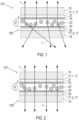
- the composite pane 100 which is designed here, for example, as a windshield of a motor vehicle, comprises a first pane 15, which serves as an outer pane, and a second pane 16 as an inner pane.
- the inner pane is the pane facing the vehicle interior, while the outer pane faces the vehicle surroundings.
- the two panes 15, 16 are made, for example, of soda-lime glass.
- the two disks 15, 16 are firmly connected to one another by a thermoplastic intermediate layer 17.
- the composite pane 100 is equipped with an electro-optical functional element 18 (see also Figures 3 and 4 ), which is, for example, a PDLC functional element.
- the PDLC functional element serves as an electrically controllable sun visor, which is attached in an area above the central viewing area B (as defined in ECE-R43).
- the PDLC functional element is formed by a commercially available PDLC multilayer film, which is embedded in the intermediate layer 17.
- the intermediate layer 17 comprises a total of three thermoplastic composite films, each of which is formed by a thermoplastic film made of PVB with a thickness of, for example, 0.38 mm.
- thermoplastic composite film 17-1 connected to the first disk 15 and a second thermoplastic composite film 17-2 connected to the second disk 16 are shown.
- the intermediate thermoplastic frame film (not shown) has a cutout into which the cut functional element 18 fits precisely. that is, inserted flush on all sides.
- the third thermoplastic composite film thus forms a kind of pas-partout for the functional element 18, which is thus encapsulated all around in thermoplastic material and is thereby protected.
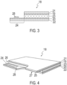
- the electrically controllable functional element 18 is a multilayer film, consisting of an active layer 23 between two surface electrodes 19, 20, and two carrier films 21, 22.
- the active layer 23 contains a polymer matrix with liquid crystals dispersed therein, which depend on the surface electrodes 19 , 20 align the applied electrical voltage S, whereby the optical properties can be regulated.
- the carrier films 21, 22 are made, for example, of PET and have a thickness of, for example, 0.125 mm.
- the carrier films 21, 22 are each provided with a coating of ITO facing the active layer 23 with a thickness of approximately 100 nm, which forms the first surface electrode 19 on the first carrier film 21 and the second surface electrode 20 on the second carrier film 22.
- the two surface electrodes 19, 20 can each be connected to the on-board electrical system via bus conductors and a single flat cable as a connecting cable, which will be explained in more detail below.
- Figure 4 shows a perspective view of the functional element 18 of the connection arrangement 101 with composite disk 100 from Figures 1 and 2 .
- a long side (longitudinal edge) of the functional element 18 is provided with two connection zones 24, 25, which serve for electrical contacting of the associated surface electrode 20, 19.
- the first carrier film 21 and the first surface electrode 19 applied thereto as well as the active layer 23 have a first cutout 26 along the longitudinal edge, which extends to the second carrier film 22 with the second surface electrode 20 applied.
- the second surface electrode 22 is therefore accessible from the side of the active layer (here from above).
- the second carrier film 22 and the second surface electrode 20 form a first connection zone 24 in the area of the first cutout 26.
- the second carrier film 22 and the applied second surface electrode 20 as well as the active layer 23 have a second cutout 27 along the same longitudinal edge extends to the first carrier film 21 and the applied first surface electrode 19.
- the first surface electrode 19 is therefore accessible from the side of the active layer 23 (here from below).
- the first carrier film 21 and the first surface electrode 19 form a second connection zone 25 in the area of the second cutout 27.
- connection zone 24, 25 is provided with a busbar, which is formed here, for example, by a silver-containing screen print.
- a busbar which is formed here, for example, by a silver-containing screen print.
- the two connection zones 24, 25 are arranged laterally offset along the longitudinal edge of the functional element 18 and are designed analogously. The statements for the first connection zone 24 therefore apply in a corresponding manner to the second connection zone 25.
- Figure 3 additionally shows a section vertically through the pane plane in the area of the first connection zone 24, which shows the second surface electrode 20 and the second carrier film 22 as well as the busbar 28 applied thereto.
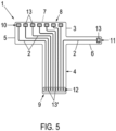
- FIG. 5 a flexible flat cable with an elongated structure, designated overall by the reference number 1, is illustrated in a schematic manner.
- the flat cable 1 is used for common connection to the two connection zones 24, 25.
- the flat cable 1 has a plurality of electrical conductor tracks 2, which are mounted on a carrier substrate 3 made of an electrically insulating material, here for example Polyimide, are applied next to each other.
- the electrical conductor tracks 2 consist of a metallic material, here for example copper, and are applied to the carrier substrate 3 using a printing process.
- the electrical conductor tracks 2 are covered by a cover layer 4, not shown, made of an electrically insulating material, here for example polyimide.
- the carrier substrate and the cover casing 4 together form an insulating casing in which the conductor tracks 2 are embedded.
- the flat cable 1 for example, has a length of 5 cm to 150 cm.
- the carrier substrate 3 and the cover layer 4 each have, for example, a thickness of 10 ⁇ m to 300 ⁇ m.
- the flat cable 1 is flexible and can easily be laminated into the composite pane and led out of it.
- the flexible flat cable 1 has a base section 5 and a strip-shaped section 6 (strip section) connected to the base section 5 (directly), which is arranged at the edge of the base section 5 and protrudes laterally from the base section 5, here for example vertically. It would also be possible for the strip-shaped section 6 to be formed by recessing the front edge 7 of the flat cable 1.
- the flat cable 1 has a first connection area 10 at a first end 8 in the base section 5 and a second connection area 11 in the strip-shaped section 6.
- the two connection areas 10, 11 are formed on the same side of the flat conductor 1 and therefore do not face each other when the strip-shaped section 6 is not folded over.
- the flat cable 1 has a third connection area 12 at its second end 9 in the base section 5.
- the cover layer 4 is removed from the connection areas 10, 11, 12, so that these connection areas 10, 11, 12 are (only) accessible from one side.
- the flat cable 1 is therefore almost completely covered by an insulating sheath made of polyimide and is therefore electrically insulated. Only the connection areas 10, 11, 12 are formed without a cover layer 4. This can be achieved, for example, by a window technology during production or by subsequent removal of the cover layer 4, for example by laser ablation.
- the flat cable 1 here, for example, has eight electrical conductor tracks 2, which are arranged next to one another on the carrier substrate 3. Seven conductor tracks 2 extend from the first connection region 10 of the base section 5 to the third connection region 12 of the base section 5. A conductor track 2 extends from the second connection region 11 of the strip-shaped section 6 to the third connection region 12 of the base section 5. Each conductor track 2 has a contact point 13 at the first end 8 and a contact point 13 'at the second end 9 of the flat cable 1.
- the contact points 13, 13 ' are designed here, for example, as solder contact points.
- the strip-shaped section 6 is elongated and can be folded over due to the flexibility of the flat cable 1.
- Figure 5 shows a situation in which the strip-shaped section 6 is not folded over, ie the surface sections of the carrier substrate 2 in the area of the base section 5 and the strip-shaped section 6, to which the conductor tracks 2 are applied, have the same orientation. This is, for example, the delivery status of the flat cable 1.
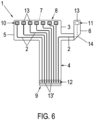
- Figure 6 a situation is shown in which the strip-shaped section 6 is folded over in a folding area 14. In the folding area 14, one side of a part of the strip-shaped section 6 comes to rest on the same side of a further part of the strip-shaped section 6.
- the angle between the extension directions of the strip-shaped section 6 in front of the folding area 14 and after the folding area 14 is here, for example, 90 °, so that the distal part of the strip-shaped section 6, ie the folded over part of the strip-shaped section 6, and the elongated base section 5 in the point in the same direction and are parallel to each other.
- the strip-shaped section 6 is not folded with sharp edges, but with a radius of curvature r of 0.1 mm to 100 mm, which means that damage to the flat conductor 1 and in particular to the conductor track 2 can be avoided.
- the first connection area 10 and the second connection area 11 are arranged on the same side of the flat cable 11. However, when folded over, as in Figure 6 shown, the second connection area 11 is rotated by 180 ° so that the two connection areas 10, 11 face each other, the second connection area 11 being arranged laterally offset from the first connection area 10. It would also be possible for the two connection areas 10, 11 to have a comparison.
- the first connection area 10 and the second connection area 11 thus have a different orientation.
- FIG 7 the electrical connection of the flat cable 1 to the two connection zones 24, 25 of the functional element 18 is illustrated schematically.
- the first connection area 10 of the base section 5 is electrically connected directly to the second connection zone 25.
- the second connection area 11 on the strip-shaped section 6 rotated by 180 ° is electrically connected directly to the first connection zone 24.
- the contact points 13 of the first connection area 10 are soldered to the busbar 28 of the second connection zone 25 from one side (direction), the contact point 13 of the second connection area 11 is soldered to the busbar of the first connection zone 24 from the other side (direction). .
- the flat cable 1 according to the invention thus advantageously enables electrical contacting of both connection zones 24, 25.
- the flat cable 1 is led out of the composite pane 100 with its base section 5, the third connection area 12 being arranged outside the composite pane 100 and being electrically connected to a control device, for example motor vehicle electronics.
- the composite disk 100 with the connected flat cable 1 forms a connection arrangement 101.
- Figure 8 shows a flowchart of a method according to the invention for producing the connection arrangement 101 according to the invention.
- connection arrangement according to the invention advantageously enables simultaneous electrical contacting of two electrically conductive structures, in particular two surface electrodes electro-optical functional element, made possible from two directions.
- the flat cable and the resulting connection arrangement can save material and costs.
- connection arrangement according to the invention is space-saving and easy to integrate into the technical environment.
Landscapes
- Chemical & Material Sciences (AREA)
- Crystallography & Structural Chemistry (AREA)
- Engineering & Computer Science (AREA)
- Manufacturing & Machinery (AREA)
- Insulated Conductors (AREA)
- Multi-Conductor Connections (AREA)
- Joining Of Glass To Other Materials (AREA)
Claims (14)
- Dispositif de connexion (101), comprenant:- une vitre composite (101) composée d'une première vitre (15) et d'une deuxième vitre (16), qui sont reliées à une couche intermédiaire (17),- deux structures conductrices d'électricité, en particulier deux électrodes de surface (19, 20) mutuellement opposées d'un élément fonctionnel électro-optique (18), qui sont disposées entre la première vitre et la deuxième vitre, et- un câble plat flexible (1) comportant des pistes conductrices électriques (2), comprenant- une première zone de connexion (10) à une première extrémité (8) et sur un premier côté du câble plat (1), dans laquelle la première zone de connexion (10) a un point de contact (13) d'au moins une piste conductrice (2),- au moins une deuxième zone de connexion (11) à la première extrémité (8) et sur le premier côté du câble plat (1), dans laquelle la deuxième zone de connexion (11) a un point de contact (13) d'au moins une piste conductrice (2),- une troisième zone de connexion (12) avec des points de contact (13') des pistes conductrices (2) à une deuxième extrémité (9) du câble plat (1),dans lequel le câble plat (1) a une section de base (5) contenant la première zone de connexion (10) et au moins une section en forme de bande (6) reliée à la section de base (5) et contenant la deuxième zone de connexion (11), dans lequel la section en forme de bande (6) est ou peut être repliée de sorte que la deuxième zone de connexion (11) soit en face de la première zone de connexion (10),dans laquelle la première zone de connexion (10) est électriquement conductrice et en particulier galvaniquement connectée à une structure électriquement conductrice et la deuxième zone de connexion (11) est électriquement conductrice et en particulier galvaniquement connectée à l'autre structure électriquement conductrice, dans laquelle le câble plat (1) est acheminé hors de la vitre composite (100) et la troisième zone de connexion (13) est disposée à l'extérieur de la vitre composite (100).
- Dispositif de connexion (101) selon la revendication 1, avec un câble plat flexible (1), dans lequel la section en forme de bande (6) est disposée sur le bord de la section de base (5).
- Dispositif de connexion (101) selon la revendication 1, avec un câble plat flexible (1), dans lequel la section en forme de bande (6) dépasse latéralement de la section de base (5), en particulier à un angle droit.
- Dispositif de connexion (101) selon l'une des revendications 1 à 3, avec un câble plat flexible (1), dans lequel la section en forme de bande (6) est ou peut être pliée de telle sorte que la deuxième zone de connexion (11) est disposée latéralement par rapport à la première zone de connexion (10).
- Dispositif de connexion (101) selon l'une des revendications 1 à 3, avec un câble plat flexible (1), dans lequel la section en forme de bande (6) est ou peut être pliée de telle sorte que la deuxième zone de connexion (11) est disposée à l'opposé de la première zone de connexion (10).
- Dispositif de connexion (101) selon l'une des revendications 1 à 5, avec un câble plat flexible (1), dans lequel une dépression d'un bord avant (7) du câble plat (1) est formée entre la section de base (5) et la section en forme de bande (6).
- Dispositif de connexion (101) selon l'une des revendications 1 à 6, avec un câble plat flexible (1), dans lequel un angle α (alpha) entre une direction d'extension de la section en forme de bande (6) devant au moins une région de pliage (14) et une direction d'extension derrière la au moins une région de pliage (14) est compris entre 10° et 170°.
- Dispositif de connexion (101) selon l'une des revendications 1 à 7, avec un câble plat flexible (1), dans lequel une partie repliée de la section en forme de bande (6) et la section de base (5) pointent dans une seule et même direction.
- Dispositif de connexion (101) selon l'une des revendications 1 à 8, avec un câble plat flexible (1), dans lequel les pistes conductrices (2) sont reliées de manière fixe à un substrat porteur (3) et sont recouvertes d'une couche de revêtement (4), dans lequel la couche de revêtement n'est pas présente, en particulier est enlevée, au moins au niveau des points de contact (13) de la première zone de raccordement (10) et de la deuxième zone de raccordement (11).
- Dispositif de connexion (101) selon l'une des revendications 1 à 8, avec un câble plat flexible (1) ayant des pistes de conducteurs électriques en forme de bande (2) qui sont laminées des deux côtés.
- Dispositif de connexion (101) selon l'une des revendications 1 à 10, avec un câble plat flexible (1), dans lequel la section en forme de bande (6) est repliée sans arêtes vives, le pli ayant un rayon de courbure r de 0,1 mm à 100 mm.
- Dispositif de connexion (101) selon l'une des revendications 1 à 11, dans lequel la première zone de connexion (10) est en contact électrique avec une première électrode de surface (19) d'un côté et la deuxième zone de connexion (11) est en contact électrique avec une deuxième électrode de surface (20) de l'autre côté.
- Procédé de fabrication d'un dispositif de connexion (101) selon l'une des revendications 1 à 12, comprenant les étapes suivantes :a) fournir un câble plat (1),b) replier la section en forme de bande (6) du câble plat (1) de manière à ce que la deuxième zone de connexion (11) soit en face de la première zone de connexion (10),c) connecter électriquement la première zone de connexion (10) à une structure électriquement conductrice et la deuxième zone de connexion (11) à l'autre structure électriquement conductrice.
- Utilisation du dispositif de connexion selon l'une des revendications 1 à 12 dans le secteur automobile ou dans le secteur de la construction, dans les meubles, les appareils électriques ou les articles de décoration pour mettre en contact au moins deux structures conductrices d'électricité, en particulier deux électrodes opposées d'un élément fonctionnel électro-optique, sur ou dans une vitre en verre de sécurité à une seule vitre ou une vitre en verre composite à plusieurs vantaux.
Applications Claiming Priority (2)
| Application Number | Priority Date | Filing Date | Title |
|---|---|---|---|
| EP20156204 | 2020-02-07 | ||
| PCT/EP2021/052879 WO2021156485A1 (fr) | 2020-02-07 | 2021-02-05 | Ensemble de raccordement doté d'un câble plat souple |
Publications (2)
| Publication Number | Publication Date |
|---|---|
| EP4100251A1 EP4100251A1 (fr) | 2022-12-14 |
| EP4100251B1 true EP4100251B1 (fr) | 2023-12-06 |
Family
ID=69528622
Family Applications (1)
| Application Number | Title | Priority Date | Filing Date |
|---|---|---|---|
| EP21708568.7A Active EP4100251B1 (fr) | 2020-02-07 | 2021-02-05 | Câble plat souple |
Country Status (7)
| Country | Link |
|---|---|
| US (1) | US20230352208A1 (fr) |
| EP (1) | EP4100251B1 (fr) |
| JP (1) | JP7534424B2 (fr) |
| KR (1) | KR20220135242A (fr) |
| CN (1) | CN113518717B (fr) |
| PL (1) | PL4100251T3 (fr) |
| WO (1) | WO2021156485A1 (fr) |
Families Citing this family (4)
| Publication number | Priority date | Publication date | Assignee | Title |
|---|---|---|---|---|
| US20240274323A1 (en) * | 2021-09-29 | 2024-08-15 | Saint-Gobain Glass France | Ribbon cable for detecting a break, connection assembly with composite panel, method for detecting a break, and use of the ribbon cable |
| DE102021213198A1 (de) * | 2021-11-23 | 2023-05-25 | Leoni Bordnetz-Systeme Gmbh | Kabelsatz sowie Verfahren zur Herstellung eines Kabelsatzes |
| WO2024126149A1 (fr) | 2022-12-14 | 2024-06-20 | Saint-Gobain Glass France | Ensemble de connexion comprenant un câble plat |
| WO2024149337A1 (fr) * | 2023-01-13 | 2024-07-18 | 福耀玻璃工业集团股份有限公司 | Élément fonctionnel à performance optique à commande électrique régionale, et verre composite |
Family Cites Families (31)
| Publication number | Priority date | Publication date | Assignee | Title |
|---|---|---|---|---|
| US3805213A (en) * | 1972-03-22 | 1974-04-16 | Data General Corp | Flexible circuit connectors |
| DE4235063A1 (de) | 1992-10-17 | 1994-04-21 | Ver Glaswerke Gmbh | Autoglasscheibe aus Verbundglas mit in der Zwischenschicht eingebetteten Drähten und einem Anschlußkabel |
| DE9313394U1 (de) | 1992-10-17 | 1993-10-28 | Vegla Vereinigte Glaswerke Gmbh, 52066 Aachen | Autoglasscheibe aus Verbundglas mit in der Zwischenschicht eingebetteten Drähten und einem Anschlußkabel |
| DE19544127C1 (de) | 1995-11-27 | 1997-03-20 | Gimsa Jan Dr | Verfahren und Vorrichtung zur Erzeugung von Resonanzerscheinungen in Partikelsuspensionen und ihre Verwendung |
| FR2757151B1 (fr) | 1996-12-12 | 1999-01-08 | Saint Gobain Vitrage | Vitrage comprenant un substrat muni d'un empilement de couches minces pour la protection solaire et/ou l'isolation thermique |
| JP3534288B2 (ja) * | 1997-03-07 | 2004-06-07 | セントラル硝子株式会社 | 調光ガラスおよびその製造方法 |
| JP3682366B2 (ja) * | 1997-12-26 | 2005-08-10 | 古河電気工業株式会社 | ワイヤハーネス及びその製造方法 |
| DE19960450C1 (de) | 1999-12-15 | 2001-05-23 | Saint Gobain | Scheibenelement und Verfahren zu seiner Herstellung |
| US7108515B2 (en) * | 2004-02-26 | 2006-09-19 | Matsushita Electric Industrial Co., Ltd. | Wiring board with bending section |
| JP2005317912A (ja) | 2004-02-26 | 2005-11-10 | Matsushita Electric Ind Co Ltd | 配線基板及びこれを用いた入力装置とその製造方法 |
| DE202004019286U1 (de) | 2004-12-14 | 2006-04-20 | Saint-Gobain Sekurit Deutschland Gmbh & Co. Kg | Flachleiter-Anschlusselement für Fensterscheiben |
| DE102005007427A1 (de) | 2005-02-18 | 2006-08-31 | Volkswagen Ag | Elektrische Sonnenblende für ein Kraftfahrzeug |
| DE102005049081B3 (de) | 2005-10-13 | 2007-06-06 | Webasto Ag | Schichtanordnung zur Abdunklung einer transparenten Scheibe |
| JP4779681B2 (ja) * | 2006-02-07 | 2011-09-28 | パナソニック株式会社 | タッチパネル |
| DE102007027296A1 (de) | 2007-06-11 | 2008-12-18 | Volkswagen Ag | Automatische Sonnenblende für ein Kraftfahrzeug |
| DE102008026339A1 (de) | 2008-05-31 | 2009-12-03 | Saint-Gobain Sekurit Deutschland Gmbh & Co. Kg | Elektrisch schaltbares Sichtschutzfenster |
| DE202008017611U1 (de) | 2008-12-20 | 2010-04-22 | Saint-Gobain Sekurit Deutschland Gmbh & Co. Kg | Scheibenförmiges, transparentes, elektrisch beheizbares Verbundmaterial |
| GB0916379D0 (en) | 2009-09-18 | 2009-10-28 | Pilkington Group Ltd | Laminated glazing |
| TWI543209B (zh) * | 2009-09-18 | 2016-07-21 | Bundled soft circuit cable | |
| US20120293470A1 (en) | 2010-02-23 | 2012-11-22 | Hideki Nakata | Image display device |
| EP2444381A1 (fr) | 2010-10-19 | 2012-04-25 | Saint-Gobain Glass France | Vitrage transparent |
| BR112015001314B1 (pt) * | 2012-08-01 | 2021-12-21 | Saint-Gobain Glass France | Painel compósito com meios de contato elétrico e método para produzir painel compósito |
| US10082716B2 (en) * | 2012-08-21 | 2018-09-25 | Saint-Gobain Glass France | Composite panel with electrically switchable optical properties |
| DE102013001334A1 (de) | 2013-01-26 | 2014-07-31 | Audi Ag | Verfahren zum Betreiben einer Fensterscheibe eines Kraftwagens sowie Kraftwagen mit einer solchen Fensterscheibe |
| WO2014123117A1 (fr) * | 2013-02-05 | 2014-08-14 | 古河電気工業株式会社 | Structure de câblage électrique, structure de raccordement électrique et procédé permettant de fabriquer une structure de câblage électrique |
| GB2528899B (en) * | 2014-08-04 | 2019-12-04 | Ford Global Tech Llc | An electrically heated laminated window |
| JP6839515B2 (ja) | 2016-09-28 | 2021-03-10 | 株式会社ビーキャット | 調光機能付き板状構造体 |
| WO2018104149A1 (fr) * | 2016-12-06 | 2018-06-14 | Saint-Gobain Glass France | Élément de raccordement d'un conducteur plat |
| KR102606536B1 (ko) | 2017-04-14 | 2023-11-27 | 셀링크 코포레이션 | 전기 하니스 조립체 |
| JPWO2019160149A1 (ja) * | 2018-02-16 | 2021-02-04 | 株式会社潤工社 | プラグコネクタ、コネクタシステム、及び飛翔体 |
| CN110418714A (zh) * | 2018-02-28 | 2019-11-05 | 法国圣戈班玻璃厂 | 包括具有电可控光学性能的功能元件的复合玻璃板 |
-
2021
- 2021-02-05 JP JP2022547762A patent/JP7534424B2/ja active Active
- 2021-02-05 KR KR1020227029707A patent/KR20220135242A/ko not_active Application Discontinuation
- 2021-02-05 WO PCT/EP2021/052879 patent/WO2021156485A1/fr unknown
- 2021-02-05 CN CN202180000657.6A patent/CN113518717B/zh active Active
- 2021-02-05 PL PL21708568.7T patent/PL4100251T3/pl unknown
- 2021-02-05 EP EP21708568.7A patent/EP4100251B1/fr active Active
- 2021-02-05 US US17/794,169 patent/US20230352208A1/en active Pending
Also Published As
| Publication number | Publication date |
|---|---|
| WO2021156485A1 (fr) | 2021-08-12 |
| EP4100251A1 (fr) | 2022-12-14 |
| US20230352208A1 (en) | 2023-11-02 |
| JP2023512543A (ja) | 2023-03-27 |
| JP7534424B2 (ja) | 2024-08-14 |
| PL4100251T3 (pl) | 2024-05-20 |
| KR20220135242A (ko) | 2022-10-06 |
| CN113518717B (zh) | 2023-10-13 |
| CN113518717A (zh) | 2021-10-19 |
Similar Documents
| Publication | Publication Date | Title |
|---|---|---|
| EP4100251B1 (fr) | Câble plat souple | |
| EP2879869B1 (fr) | Plaque de verre feuilletée avec mise en contact électrique | |
| DE102004050158B3 (de) | Transparente Scheibe mit einer beheizbaren Beschichtung | |
| EP3372051B1 (fr) | Vitre composite pouvant être chauffée électriquement présentant une zone de commutation capacitive | |
| EP3189706B1 (fr) | Vitre avec zone de chauffage électrique | |
| WO2020083562A1 (fr) | Verre feuilleté doté d'un élément fonctionnel commutable par segments et aux propriétés optiques aptes à être commandées par voie électrique | |
| EP3870440B1 (fr) | Vitre feuilletée dotée d'un élément fonctionnel commutable par segments présentant des propriétés optiques à commande électrique | |
| DE202018102520U1 (de) | Verbundscheibe mit einem Funktionselement | |
| WO2015014511A1 (fr) | Vitre latérale stratifiée pouvant être chauffée | |
| WO2021209474A1 (fr) | Élément fonctionnel doté de propriétés optiques pouvant être commandées électriquement | |
| DE202021105230U1 (de) | Anschlussanordnung mit Schutzgehäuse | |
| EP4101030B1 (fr) | Élément de connexion pour un conducteur plat | |
| DE202021105089U1 (de) | Verglasung mit segmentiertem PDLC-Funktionselement und elektrisch steuerbaren optischen Eigenschaften | |
| EP4100250B1 (fr) | Agencement de raccordement pourvu de disque composite et élément fonctionnel | |
| WO2019166210A1 (fr) | Vitre composite dotée d'un élément réfléchissant le rayonnement infrarouge | |
| EP2146548A2 (fr) | Vitre transparente dotée d'un revêtement pouvant être chauffé et de structures conductrices de basse impédance | |
| EP4106992B1 (fr) | Vitre composite pourvue d'une pluralité d'éléments fonctionnels et barre omnibus sur une feuille barrière | |
| WO2018104149A1 (fr) | Élément de raccordement d'un conducteur plat | |
| WO2021197949A1 (fr) | Procédé de production d'une vitre composite présentant propriété optique pouvant être commandée électriquement | |
| EP4281285A1 (fr) | Vitre composite comprenant des propriétés optiques pouvant être commandées électriquement, et unité de commande | |
| WO2021069354A1 (fr) | Procédé de fabrication d'une vitre composite dotée d'un élément fonctionnel | |
| DE202020005428U1 (de) | Verbundscheibe mit elektrisch steuerbaren optischen Eigenschaften und Verbundscheibenanordnung | |
| WO2024126149A1 (fr) | Ensemble de connexion comprenant un câble plat | |
| WO2024002685A1 (fr) | Câble plat, ligne de connexion électrique, substrat et vitre composite | |
| EP4409610A1 (fr) | Câble plat pour détection de rupture, ensemble de connexion avec panneau composite, procédé de détection de rupture et utilisation du câble plat |
Legal Events
| Date | Code | Title | Description |
|---|---|---|---|
| STAA | Information on the status of an ep patent application or granted ep patent |
Free format text: STATUS: UNKNOWN |
|
| STAA | Information on the status of an ep patent application or granted ep patent |
Free format text: STATUS: THE INTERNATIONAL PUBLICATION HAS BEEN MADE |
|
| PUAI | Public reference made under article 153(3) epc to a published international application that has entered the european phase |
Free format text: ORIGINAL CODE: 0009012 |
|
| STAA | Information on the status of an ep patent application or granted ep patent |
Free format text: STATUS: REQUEST FOR EXAMINATION WAS MADE |
|
| 17P | Request for examination filed |
Effective date: 20220901 |
|
| AK | Designated contracting states |
Kind code of ref document: A1 Designated state(s): AL AT BE BG CH CY CZ DE DK EE ES FI FR GB GR HR HU IE IS IT LI LT LU LV MC MK MT NL NO PL PT RO RS SE SI SK SM TR |
|
| DAV | Request for validation of the european patent (deleted) | ||
| DAX | Request for extension of the european patent (deleted) | ||
| GRAP | Despatch of communication of intention to grant a patent |
Free format text: ORIGINAL CODE: EPIDOSNIGR1 |
|
| STAA | Information on the status of an ep patent application or granted ep patent |
Free format text: STATUS: GRANT OF PATENT IS INTENDED |
|
| INTG | Intention to grant announced |
Effective date: 20230615 |
|
| GRAS | Grant fee paid |
Free format text: ORIGINAL CODE: EPIDOSNIGR3 |
|
| GRAA | (expected) grant |
Free format text: ORIGINAL CODE: 0009210 |
|
| STAA | Information on the status of an ep patent application or granted ep patent |
Free format text: STATUS: THE PATENT HAS BEEN GRANTED |
|
| AK | Designated contracting states |
Kind code of ref document: B1 Designated state(s): AL AT BE BG CH CY CZ DE DK EE ES FI FR GB GR HR HU IE IS IT LI LT LU LV MC MK MT NL NO PL PT RO RS SE SI SK SM TR |
|
| REG | Reference to a national code |
Ref country code: GB Ref legal event code: FG4D Free format text: NOT ENGLISH |
|
| REG | Reference to a national code |
Ref country code: DE Ref legal event code: R096 Ref document number: 502021002129 Country of ref document: DE |
|
| REG | Reference to a national code |
Ref country code: CH Ref legal event code: EP |
|
| REG | Reference to a national code |
Ref country code: IE Ref legal event code: FG4D Free format text: LANGUAGE OF EP DOCUMENT: GERMAN |
|
| REG | Reference to a national code |
Ref country code: LT Ref legal event code: MG9D |
|
| PG25 | Lapsed in a contracting state [announced via postgrant information from national office to epo] |
Ref country code: GR Free format text: LAPSE BECAUSE OF FAILURE TO SUBMIT A TRANSLATION OF THE DESCRIPTION OR TO PAY THE FEE WITHIN THE PRESCRIBED TIME-LIMIT Effective date: 20240307 |
|
| REG | Reference to a national code |
Ref country code: NL Ref legal event code: MP Effective date: 20231206 |
|
| PG25 | Lapsed in a contracting state [announced via postgrant information from national office to epo] |
Ref country code: LT Free format text: LAPSE BECAUSE OF FAILURE TO SUBMIT A TRANSLATION OF THE DESCRIPTION OR TO PAY THE FEE WITHIN THE PRESCRIBED TIME-LIMIT Effective date: 20231206 |
|
| PG25 | Lapsed in a contracting state [announced via postgrant information from national office to epo] |
Ref country code: ES Free format text: LAPSE BECAUSE OF FAILURE TO SUBMIT A TRANSLATION OF THE DESCRIPTION OR TO PAY THE FEE WITHIN THE PRESCRIBED TIME-LIMIT Effective date: 20231206 |
|
| PG25 | Lapsed in a contracting state [announced via postgrant information from national office to epo] |
Ref country code: LT Free format text: LAPSE BECAUSE OF FAILURE TO SUBMIT A TRANSLATION OF THE DESCRIPTION OR TO PAY THE FEE WITHIN THE PRESCRIBED TIME-LIMIT Effective date: 20231206 Ref country code: GR Free format text: LAPSE BECAUSE OF FAILURE TO SUBMIT A TRANSLATION OF THE DESCRIPTION OR TO PAY THE FEE WITHIN THE PRESCRIBED TIME-LIMIT Effective date: 20240307 Ref country code: ES Free format text: LAPSE BECAUSE OF FAILURE TO SUBMIT A TRANSLATION OF THE DESCRIPTION OR TO PAY THE FEE WITHIN THE PRESCRIBED TIME-LIMIT Effective date: 20231206 Ref country code: BG Free format text: LAPSE BECAUSE OF FAILURE TO SUBMIT A TRANSLATION OF THE DESCRIPTION OR TO PAY THE FEE WITHIN THE PRESCRIBED TIME-LIMIT Effective date: 20240306 |
|
| PGFP | Annual fee paid to national office [announced via postgrant information from national office to epo] |
Ref country code: DE Payment date: 20231229 Year of fee payment: 4 |
|
| PG25 | Lapsed in a contracting state [announced via postgrant information from national office to epo] |
Ref country code: NL Free format text: LAPSE BECAUSE OF FAILURE TO SUBMIT A TRANSLATION OF THE DESCRIPTION OR TO PAY THE FEE WITHIN THE PRESCRIBED TIME-LIMIT Effective date: 20231206 |
|
| PG25 | Lapsed in a contracting state [announced via postgrant information from national office to epo] |
Ref country code: SE Free format text: LAPSE BECAUSE OF FAILURE TO SUBMIT A TRANSLATION OF THE DESCRIPTION OR TO PAY THE FEE WITHIN THE PRESCRIBED TIME-LIMIT Effective date: 20231206 Ref country code: RS Free format text: LAPSE BECAUSE OF FAILURE TO SUBMIT A TRANSLATION OF THE DESCRIPTION OR TO PAY THE FEE WITHIN THE PRESCRIBED TIME-LIMIT Effective date: 20231206 Ref country code: NO Free format text: LAPSE BECAUSE OF FAILURE TO SUBMIT A TRANSLATION OF THE DESCRIPTION OR TO PAY THE FEE WITHIN THE PRESCRIBED TIME-LIMIT Effective date: 20240306 Ref country code: NL Free format text: LAPSE BECAUSE OF FAILURE TO SUBMIT A TRANSLATION OF THE DESCRIPTION OR TO PAY THE FEE WITHIN THE PRESCRIBED TIME-LIMIT Effective date: 20231206 Ref country code: LV Free format text: LAPSE BECAUSE OF FAILURE TO SUBMIT A TRANSLATION OF THE DESCRIPTION OR TO PAY THE FEE WITHIN THE PRESCRIBED TIME-LIMIT Effective date: 20231206 Ref country code: HR Free format text: LAPSE BECAUSE OF FAILURE TO SUBMIT A TRANSLATION OF THE DESCRIPTION OR TO PAY THE FEE WITHIN THE PRESCRIBED TIME-LIMIT Effective date: 20231206 |
|
| PGFP | Annual fee paid to national office [announced via postgrant information from national office to epo] |
Ref country code: TR Payment date: 20240202 Year of fee payment: 4 Ref country code: FR Payment date: 20240103 Year of fee payment: 4 |
|
| PG25 | Lapsed in a contracting state [announced via postgrant information from national office to epo] |
Ref country code: IS Free format text: LAPSE BECAUSE OF FAILURE TO SUBMIT A TRANSLATION OF THE DESCRIPTION OR TO PAY THE FEE WITHIN THE PRESCRIBED TIME-LIMIT Effective date: 20240406 |
|
| PG25 | Lapsed in a contracting state [announced via postgrant information from national office to epo] |
Ref country code: CZ Free format text: LAPSE BECAUSE OF FAILURE TO SUBMIT A TRANSLATION OF THE DESCRIPTION OR TO PAY THE FEE WITHIN THE PRESCRIBED TIME-LIMIT Effective date: 20231206 |
|
| PG25 | Lapsed in a contracting state [announced via postgrant information from national office to epo] |
Ref country code: SK Free format text: LAPSE BECAUSE OF FAILURE TO SUBMIT A TRANSLATION OF THE DESCRIPTION OR TO PAY THE FEE WITHIN THE PRESCRIBED TIME-LIMIT Effective date: 20231206 |
|
| PG25 | Lapsed in a contracting state [announced via postgrant information from national office to epo] |
Ref country code: SM Free format text: LAPSE BECAUSE OF FAILURE TO SUBMIT A TRANSLATION OF THE DESCRIPTION OR TO PAY THE FEE WITHIN THE PRESCRIBED TIME-LIMIT Effective date: 20231206 Ref country code: SK Free format text: LAPSE BECAUSE OF FAILURE TO SUBMIT A TRANSLATION OF THE DESCRIPTION OR TO PAY THE FEE WITHIN THE PRESCRIBED TIME-LIMIT Effective date: 20231206 Ref country code: RO Free format text: LAPSE BECAUSE OF FAILURE TO SUBMIT A TRANSLATION OF THE DESCRIPTION OR TO PAY THE FEE WITHIN THE PRESCRIBED TIME-LIMIT Effective date: 20231206 Ref country code: IT Free format text: LAPSE BECAUSE OF FAILURE TO SUBMIT A TRANSLATION OF THE DESCRIPTION OR TO PAY THE FEE WITHIN THE PRESCRIBED TIME-LIMIT Effective date: 20231206 Ref country code: IS Free format text: LAPSE BECAUSE OF FAILURE TO SUBMIT A TRANSLATION OF THE DESCRIPTION OR TO PAY THE FEE WITHIN THE PRESCRIBED TIME-LIMIT Effective date: 20240406 Ref country code: EE Free format text: LAPSE BECAUSE OF FAILURE TO SUBMIT A TRANSLATION OF THE DESCRIPTION OR TO PAY THE FEE WITHIN THE PRESCRIBED TIME-LIMIT Effective date: 20231206 Ref country code: CZ Free format text: LAPSE BECAUSE OF FAILURE TO SUBMIT A TRANSLATION OF THE DESCRIPTION OR TO PAY THE FEE WITHIN THE PRESCRIBED TIME-LIMIT Effective date: 20231206 |
|
| PG25 | Lapsed in a contracting state [announced via postgrant information from national office to epo] |
Ref country code: PT Free format text: LAPSE BECAUSE OF FAILURE TO SUBMIT A TRANSLATION OF THE DESCRIPTION OR TO PAY THE FEE WITHIN THE PRESCRIBED TIME-LIMIT Effective date: 20240408 |
|
| PGFP | Annual fee paid to national office [announced via postgrant information from national office to epo] |
Ref country code: PL Payment date: 20240105 Year of fee payment: 4 |
|
| PG25 | Lapsed in a contracting state [announced via postgrant information from national office to epo] |
Ref country code: PT Free format text: LAPSE BECAUSE OF FAILURE TO SUBMIT A TRANSLATION OF THE DESCRIPTION OR TO PAY THE FEE WITHIN THE PRESCRIBED TIME-LIMIT Effective date: 20240408 |