EP4100251B1 - Flexible flat cable - Google Patents
Flexible flat cable Download PDFInfo
- Publication number
- EP4100251B1 EP4100251B1 EP21708568.7A EP21708568A EP4100251B1 EP 4100251 B1 EP4100251 B1 EP 4100251B1 EP 21708568 A EP21708568 A EP 21708568A EP 4100251 B1 EP4100251 B1 EP 4100251B1
- Authority
- EP
- European Patent Office
- Prior art keywords
- flat cable
- connection
- connection region
- strip
- pane
- Prior art date
- Legal status (The legal status is an assumption and is not a legal conclusion. Google has not performed a legal analysis and makes no representation as to the accuracy of the status listed.)
- Active
Links
- 230000009975 flexible effect Effects 0.000 title claims description 45
- 239000004020 conductor Substances 0.000 claims description 88
- 239000002131 composite material Substances 0.000 claims description 54
- 239000000758 substrate Substances 0.000 claims description 19
- 239000011521 glass Substances 0.000 claims description 11
- 238000004519 manufacturing process Methods 0.000 claims description 8
- 238000010276 construction Methods 0.000 claims description 4
- 239000005336 safety glass Substances 0.000 claims description 2
- 239000010410 layer Substances 0.000 description 94
- 229920001169 thermoplastic Polymers 0.000 description 37
- 239000004416 thermosoftening plastic Substances 0.000 description 37
- 238000009413 insulation Methods 0.000 description 19
- 238000000034 method Methods 0.000 description 12
- 229910052751 metal Inorganic materials 0.000 description 11
- 239000002184 metal Substances 0.000 description 11
- 239000004983 Polymer Dispersed Liquid Crystal Substances 0.000 description 10
- 238000000576 coating method Methods 0.000 description 8
- -1 polypropylene Polymers 0.000 description 8
- 230000005540 biological transmission Effects 0.000 description 7
- 239000000463 material Substances 0.000 description 6
- 229920002037 poly(vinyl butyral) polymer Polymers 0.000 description 6
- 229920000139 polyethylene terephthalate Polymers 0.000 description 6
- 239000005020 polyethylene terephthalate Substances 0.000 description 6
- BQCADISMDOOEFD-UHFFFAOYSA-N Silver Chemical compound [Ag] BQCADISMDOOEFD-UHFFFAOYSA-N 0.000 description 5
- 239000012790 adhesive layer Substances 0.000 description 5
- 239000011888 foil Substances 0.000 description 5
- 229920003023 plastic Polymers 0.000 description 5
- 239000004033 plastic Substances 0.000 description 5
- 229910052709 silver Inorganic materials 0.000 description 5
- 239000004332 silver Substances 0.000 description 5
- RYGMFSIKBFXOCR-UHFFFAOYSA-N Copper Chemical compound [Cu] RYGMFSIKBFXOCR-UHFFFAOYSA-N 0.000 description 4
- 239000004642 Polyimide Substances 0.000 description 4
- 229910052802 copper Inorganic materials 0.000 description 4
- 239000010949 copper Substances 0.000 description 4
- 230000007797 corrosion Effects 0.000 description 4
- 238000005260 corrosion Methods 0.000 description 4
- 239000002346 layers by function Substances 0.000 description 4
- 230000003287 optical effect Effects 0.000 description 4
- 229920001721 polyimide Polymers 0.000 description 4
- 238000007639 printing Methods 0.000 description 4
- 238000005476 soldering Methods 0.000 description 4
- 239000000853 adhesive Substances 0.000 description 3
- 230000001070 adhesive effect Effects 0.000 description 3
- 238000005520 cutting process Methods 0.000 description 3
- 238000010292 electrical insulation Methods 0.000 description 3
- 239000012777 electrically insulating material Substances 0.000 description 3
- 239000005340 laminated glass Substances 0.000 description 3
- 239000004973 liquid crystal related substance Substances 0.000 description 3
- 229910001092 metal group alloy Inorganic materials 0.000 description 3
- 229910000679 solder Inorganic materials 0.000 description 3
- 239000002966 varnish Substances 0.000 description 3
- PXHVJJICTQNCMI-UHFFFAOYSA-N Nickel Chemical compound [Ni] PXHVJJICTQNCMI-UHFFFAOYSA-N 0.000 description 2
- 239000004743 Polypropylene Substances 0.000 description 2
- ATJFFYVFTNAWJD-UHFFFAOYSA-N Tin Chemical compound [Sn] ATJFFYVFTNAWJD-UHFFFAOYSA-N 0.000 description 2
- 229910045601 alloy Inorganic materials 0.000 description 2
- 239000000956 alloy Substances 0.000 description 2
- 230000005670 electromagnetic radiation Effects 0.000 description 2
- 238000005516 engineering process Methods 0.000 description 2
- 239000005038 ethylene vinyl acetate Substances 0.000 description 2
- PCHJSUWPFVWCPO-UHFFFAOYSA-N gold Chemical compound [Au] PCHJSUWPFVWCPO-UHFFFAOYSA-N 0.000 description 2
- 229910052737 gold Inorganic materials 0.000 description 2
- 239000010931 gold Substances 0.000 description 2
- 238000010438 heat treatment Methods 0.000 description 2
- 238000003475 lamination Methods 0.000 description 2
- 238000000608 laser ablation Methods 0.000 description 2
- 239000007769 metal material Substances 0.000 description 2
- 230000002093 peripheral effect Effects 0.000 description 2
- 229920003229 poly(methyl methacrylate) Polymers 0.000 description 2
- 239000004417 polycarbonate Substances 0.000 description 2
- 229920000515 polycarbonate Polymers 0.000 description 2
- 229920000642 polymer Polymers 0.000 description 2
- 239000004926 polymethyl methacrylate Substances 0.000 description 2
- 229920001155 polypropylene Polymers 0.000 description 2
- 239000011241 protective layer Substances 0.000 description 2
- 230000001105 regulatory effect Effects 0.000 description 2
- 229920005989 resin Polymers 0.000 description 2
- 239000011347 resin Substances 0.000 description 2
- 239000005361 soda-lime glass Substances 0.000 description 2
- 230000003595 spectral effect Effects 0.000 description 2
- 239000011135 tin Substances 0.000 description 2
- 229910052718 tin Inorganic materials 0.000 description 2
- NIXOWILDQLNWCW-UHFFFAOYSA-M Acrylate Chemical compound [O-]C(=O)C=C NIXOWILDQLNWCW-UHFFFAOYSA-M 0.000 description 1
- 239000004925 Acrylic resin Substances 0.000 description 1
- 229920002799 BoPET Polymers 0.000 description 1
- VYZAMTAEIAYCRO-UHFFFAOYSA-N Chromium Chemical compound [Cr] VYZAMTAEIAYCRO-UHFFFAOYSA-N 0.000 description 1
- 229920002943 EPDM rubber Polymers 0.000 description 1
- 239000004812 Fluorinated ethylene propylene Substances 0.000 description 1
- 229930040373 Paraformaldehyde Natural products 0.000 description 1
- 239000004952 Polyamide Substances 0.000 description 1
- 239000004698 Polyethylene Substances 0.000 description 1
- VYPSYNLAJGMNEJ-UHFFFAOYSA-N Silicium dioxide Chemical compound O=[Si]=O VYPSYNLAJGMNEJ-UHFFFAOYSA-N 0.000 description 1
- 150000001252 acrylic acid derivatives Chemical class 0.000 description 1
- 238000004026 adhesive bonding Methods 0.000 description 1
- 229910052782 aluminium Inorganic materials 0.000 description 1
- XAGFODPZIPBFFR-UHFFFAOYSA-N aluminium Chemical compound [Al] XAGFODPZIPBFFR-UHFFFAOYSA-N 0.000 description 1
- 239000006117 anti-reflective coating Substances 0.000 description 1
- 230000004888 barrier function Effects 0.000 description 1
- 239000005388 borosilicate glass Substances 0.000 description 1
- 238000005266 casting Methods 0.000 description 1
- 229910052804 chromium Inorganic materials 0.000 description 1
- 239000011651 chromium Substances 0.000 description 1
- 239000011248 coating agent Substances 0.000 description 1
- 238000004040 coloring Methods 0.000 description 1
- 210000003298 dental enamel Anatomy 0.000 description 1
- 229920001971 elastomer Polymers 0.000 description 1
- 239000000806 elastomer Substances 0.000 description 1
- 239000012799 electrically-conductive coating Substances 0.000 description 1
- 239000003822 epoxy resin Substances 0.000 description 1
- 229920000840 ethylene tetrafluoroethylene copolymer Polymers 0.000 description 1
- 238000009499 grossing Methods 0.000 description 1
- 239000011229 interlayer Substances 0.000 description 1
- 238000010030 laminating Methods 0.000 description 1
- 239000011159 matrix material Substances 0.000 description 1
- 238000002844 melting Methods 0.000 description 1
- 229910052759 nickel Inorganic materials 0.000 description 1
- 239000002245 particle Substances 0.000 description 1
- 229920009441 perflouroethylene propylene Polymers 0.000 description 1
- 230000001699 photocatalysis Effects 0.000 description 1
- 238000007747 plating Methods 0.000 description 1
- 229920000058 polyacrylate Polymers 0.000 description 1
- 229920002647 polyamide Polymers 0.000 description 1
- 229920001707 polybutylene terephthalate Polymers 0.000 description 1
- 229920000647 polyepoxide Polymers 0.000 description 1
- 229920000728 polyester Polymers 0.000 description 1
- 229920000573 polyethylene Polymers 0.000 description 1
- 239000011112 polyethylene naphthalate Substances 0.000 description 1
- 229920006324 polyoxymethylene Polymers 0.000 description 1
- 239000004814 polyurethane Substances 0.000 description 1
- 229920000915 polyvinyl chloride Polymers 0.000 description 1
- 239000004800 polyvinyl chloride Substances 0.000 description 1
- 229920002620 polyvinyl fluoride Polymers 0.000 description 1
- 238000004382 potting Methods 0.000 description 1
- 230000001681 protective effect Effects 0.000 description 1
- 230000005855 radiation Effects 0.000 description 1
- 238000007650 screen-printing Methods 0.000 description 1
- 230000000087 stabilizing effect Effects 0.000 description 1
- 229910001220 stainless steel Inorganic materials 0.000 description 1
- 239000010935 stainless steel Substances 0.000 description 1
- 230000037072 sun protection Effects 0.000 description 1
- 239000012815 thermoplastic material Substances 0.000 description 1
- 238000003466 welding Methods 0.000 description 1
Images


Classifications
-
- B—PERFORMING OPERATIONS; TRANSPORTING
- B32—LAYERED PRODUCTS
- B32B—LAYERED PRODUCTS, i.e. PRODUCTS BUILT-UP OF STRATA OF FLAT OR NON-FLAT, e.g. CELLULAR OR HONEYCOMB, FORM
- B32B27/00—Layered products comprising a layer of synthetic resin
- B32B27/30—Layered products comprising a layer of synthetic resin comprising vinyl (co)polymers; comprising acrylic (co)polymers
- B32B27/306—Layered products comprising a layer of synthetic resin comprising vinyl (co)polymers; comprising acrylic (co)polymers comprising vinyl acetate or vinyl alcohol (co)polymers
-
- H—ELECTRICITY
- H01—ELECTRIC ELEMENTS
- H01B—CABLES; CONDUCTORS; INSULATORS; SELECTION OF MATERIALS FOR THEIR CONDUCTIVE, INSULATING OR DIELECTRIC PROPERTIES
- H01B7/00—Insulated conductors or cables characterised by their form
- H01B7/08—Flat or ribbon cables
-
- B—PERFORMING OPERATIONS; TRANSPORTING
- B32—LAYERED PRODUCTS
- B32B—LAYERED PRODUCTS, i.e. PRODUCTS BUILT-UP OF STRATA OF FLAT OR NON-FLAT, e.g. CELLULAR OR HONEYCOMB, FORM
- B32B17/00—Layered products essentially comprising sheet glass, or glass, slag, or like fibres
- B32B17/06—Layered products essentially comprising sheet glass, or glass, slag, or like fibres comprising glass as the main or only constituent of a layer, next to another layer of a specific material
- B32B17/10—Layered products essentially comprising sheet glass, or glass, slag, or like fibres comprising glass as the main or only constituent of a layer, next to another layer of a specific material of synthetic resin
- B32B17/10005—Layered products essentially comprising sheet glass, or glass, slag, or like fibres comprising glass as the main or only constituent of a layer, next to another layer of a specific material of synthetic resin laminated safety glass or glazing
- B32B17/10009—Layered products essentially comprising sheet glass, or glass, slag, or like fibres comprising glass as the main or only constituent of a layer, next to another layer of a specific material of synthetic resin laminated safety glass or glazing characterized by the number, the constitution or treatment of glass sheets
- B32B17/10036—Layered products essentially comprising sheet glass, or glass, slag, or like fibres comprising glass as the main or only constituent of a layer, next to another layer of a specific material of synthetic resin laminated safety glass or glazing characterized by the number, the constitution or treatment of glass sheets comprising two outer glass sheets
-
- B—PERFORMING OPERATIONS; TRANSPORTING
- B32—LAYERED PRODUCTS
- B32B—LAYERED PRODUCTS, i.e. PRODUCTS BUILT-UP OF STRATA OF FLAT OR NON-FLAT, e.g. CELLULAR OR HONEYCOMB, FORM
- B32B17/00—Layered products essentially comprising sheet glass, or glass, slag, or like fibres
- B32B17/06—Layered products essentially comprising sheet glass, or glass, slag, or like fibres comprising glass as the main or only constituent of a layer, next to another layer of a specific material
- B32B17/10—Layered products essentially comprising sheet glass, or glass, slag, or like fibres comprising glass as the main or only constituent of a layer, next to another layer of a specific material of synthetic resin
- B32B17/10005—Layered products essentially comprising sheet glass, or glass, slag, or like fibres comprising glass as the main or only constituent of a layer, next to another layer of a specific material of synthetic resin laminated safety glass or glazing
- B32B17/10165—Functional features of the laminated safety glass or glazing
- B32B17/10293—Edge features, e.g. inserts or holes
-
- B—PERFORMING OPERATIONS; TRANSPORTING
- B32—LAYERED PRODUCTS
- B32B—LAYERED PRODUCTS, i.e. PRODUCTS BUILT-UP OF STRATA OF FLAT OR NON-FLAT, e.g. CELLULAR OR HONEYCOMB, FORM
- B32B17/00—Layered products essentially comprising sheet glass, or glass, slag, or like fibres
- B32B17/06—Layered products essentially comprising sheet glass, or glass, slag, or like fibres comprising glass as the main or only constituent of a layer, next to another layer of a specific material
- B32B17/10—Layered products essentially comprising sheet glass, or glass, slag, or like fibres comprising glass as the main or only constituent of a layer, next to another layer of a specific material of synthetic resin
- B32B17/10005—Layered products essentially comprising sheet glass, or glass, slag, or like fibres comprising glass as the main or only constituent of a layer, next to another layer of a specific material of synthetic resin laminated safety glass or glazing
- B32B17/10165—Functional features of the laminated safety glass or glazing
- B32B17/10431—Specific parts for the modulation of light incorporated into the laminated safety glass or glazing
- B32B17/10467—Variable transmission
- B32B17/10495—Variable transmission optoelectronic, i.e. optical valve
- B32B17/10504—Liquid crystal layer
-
- B—PERFORMING OPERATIONS; TRANSPORTING
- B32—LAYERED PRODUCTS
- B32B—LAYERED PRODUCTS, i.e. PRODUCTS BUILT-UP OF STRATA OF FLAT OR NON-FLAT, e.g. CELLULAR OR HONEYCOMB, FORM
- B32B17/00—Layered products essentially comprising sheet glass, or glass, slag, or like fibres
- B32B17/06—Layered products essentially comprising sheet glass, or glass, slag, or like fibres comprising glass as the main or only constituent of a layer, next to another layer of a specific material
- B32B17/10—Layered products essentially comprising sheet glass, or glass, slag, or like fibres comprising glass as the main or only constituent of a layer, next to another layer of a specific material of synthetic resin
- B32B17/10005—Layered products essentially comprising sheet glass, or glass, slag, or like fibres comprising glass as the main or only constituent of a layer, next to another layer of a specific material of synthetic resin laminated safety glass or glazing
- B32B17/1055—Layered products essentially comprising sheet glass, or glass, slag, or like fibres comprising glass as the main or only constituent of a layer, next to another layer of a specific material of synthetic resin laminated safety glass or glazing characterized by the resin layer, i.e. interlayer
- B32B17/10761—Layered products essentially comprising sheet glass, or glass, slag, or like fibres comprising glass as the main or only constituent of a layer, next to another layer of a specific material of synthetic resin laminated safety glass or glazing characterized by the resin layer, i.e. interlayer containing vinyl acetal
-
- B—PERFORMING OPERATIONS; TRANSPORTING
- B32—LAYERED PRODUCTS
- B32B—LAYERED PRODUCTS, i.e. PRODUCTS BUILT-UP OF STRATA OF FLAT OR NON-FLAT, e.g. CELLULAR OR HONEYCOMB, FORM
- B32B27/00—Layered products comprising a layer of synthetic resin
- B32B27/06—Layered products comprising a layer of synthetic resin as the main or only constituent of a layer, which is next to another layer of the same or of a different material
- B32B27/08—Layered products comprising a layer of synthetic resin as the main or only constituent of a layer, which is next to another layer of the same or of a different material of synthetic resin
-
- B—PERFORMING OPERATIONS; TRANSPORTING
- B32—LAYERED PRODUCTS
- B32B—LAYERED PRODUCTS, i.e. PRODUCTS BUILT-UP OF STRATA OF FLAT OR NON-FLAT, e.g. CELLULAR OR HONEYCOMB, FORM
- B32B27/00—Layered products comprising a layer of synthetic resin
- B32B27/36—Layered products comprising a layer of synthetic resin comprising polyesters
-
- B—PERFORMING OPERATIONS; TRANSPORTING
- B32—LAYERED PRODUCTS
- B32B—LAYERED PRODUCTS, i.e. PRODUCTS BUILT-UP OF STRATA OF FLAT OR NON-FLAT, e.g. CELLULAR OR HONEYCOMB, FORM
- B32B3/00—Layered products comprising a layer with external or internal discontinuities or unevennesses, or a layer of non-planar form; Layered products having particular features of form
- B32B3/02—Layered products comprising a layer with external or internal discontinuities or unevennesses, or a layer of non-planar form; Layered products having particular features of form characterised by features of form at particular places, e.g. in edge regions
- B32B3/08—Layered products comprising a layer with external or internal discontinuities or unevennesses, or a layer of non-planar form; Layered products having particular features of form characterised by features of form at particular places, e.g. in edge regions characterised by added members at particular parts
-
- H—ELECTRICITY
- H01—ELECTRIC ELEMENTS
- H01B—CABLES; CONDUCTORS; INSULATORS; SELECTION OF MATERIALS FOR THEIR CONDUCTIVE, INSULATING OR DIELECTRIC PROPERTIES
- H01B13/00—Apparatus or processes specially adapted for manufacturing conductors or cables
- H01B13/0036—Details
-
- H—ELECTRICITY
- H01—ELECTRIC ELEMENTS
- H01B—CABLES; CONDUCTORS; INSULATORS; SELECTION OF MATERIALS FOR THEIR CONDUCTIVE, INSULATING OR DIELECTRIC PROPERTIES
- H01B7/00—Insulated conductors or cables characterised by their form
- H01B7/04—Flexible cables, conductors, or cords, e.g. trailing cables
- H01B7/041—Flexible cables, conductors, or cords, e.g. trailing cables attached to mobile objects, e.g. portable tools, elevators, mining equipment, hoisting cables
-
- H—ELECTRICITY
- H01—ELECTRIC ELEMENTS
- H01B—CABLES; CONDUCTORS; INSULATORS; SELECTION OF MATERIALS FOR THEIR CONDUCTIVE, INSULATING OR DIELECTRIC PROPERTIES
- H01B7/00—Insulated conductors or cables characterised by their form
- H01B7/17—Protection against damage caused by external factors, e.g. sheaths or armouring
-
- H—ELECTRICITY
- H02—GENERATION; CONVERSION OR DISTRIBUTION OF ELECTRIC POWER
- H02G—INSTALLATION OF ELECTRIC CABLES OR LINES, OR OF COMBINED OPTICAL AND ELECTRIC CABLES OR LINES
- H02G15/00—Cable fittings
- H02G15/08—Cable junctions
-
- B—PERFORMING OPERATIONS; TRANSPORTING
- B32—LAYERED PRODUCTS
- B32B—LAYERED PRODUCTS, i.e. PRODUCTS BUILT-UP OF STRATA OF FLAT OR NON-FLAT, e.g. CELLULAR OR HONEYCOMB, FORM
- B32B2255/00—Coating on the layer surface
- B32B2255/10—Coating on the layer surface on synthetic resin layer or on natural or synthetic rubber layer
-
- B—PERFORMING OPERATIONS; TRANSPORTING
- B32—LAYERED PRODUCTS
- B32B—LAYERED PRODUCTS, i.e. PRODUCTS BUILT-UP OF STRATA OF FLAT OR NON-FLAT, e.g. CELLULAR OR HONEYCOMB, FORM
- B32B2255/00—Coating on the layer surface
- B32B2255/20—Inorganic coating
-
- B—PERFORMING OPERATIONS; TRANSPORTING
- B32—LAYERED PRODUCTS
- B32B—LAYERED PRODUCTS, i.e. PRODUCTS BUILT-UP OF STRATA OF FLAT OR NON-FLAT, e.g. CELLULAR OR HONEYCOMB, FORM
- B32B2307/00—Properties of the layers or laminate
- B32B2307/20—Properties of the layers or laminate having particular electrical or magnetic properties, e.g. piezoelectric
- B32B2307/202—Conductive
-
- B—PERFORMING OPERATIONS; TRANSPORTING
- B32—LAYERED PRODUCTS
- B32B—LAYERED PRODUCTS, i.e. PRODUCTS BUILT-UP OF STRATA OF FLAT OR NON-FLAT, e.g. CELLULAR OR HONEYCOMB, FORM
- B32B2457/00—Electrical equipment
Definitions
- the invention relates to a connection arrangement with a flexible flat cable with electrical conductor tracks, as well as a method for its production and its use.
- Flexible flat conductors also known as ribbon conductors or foil conductors, are often used in vehicle construction, in particular to enable movable electrical contacting in limited space conditions.
- flat conductors are used, for example, to contact electrically functional layers in laminated glass panes. Examples can be found in DE 42 35 063 A1 , DE 20 2004 019 286 U1 or DE 93 13 394 U1 .
- Such laminated glass panes usually consist of at least two rigid individual glass panes, which are adhesively connected to one another using a thermoplastic adhesive layer.
- the thickness of the adhesive layer is, for example, 0.76 mm.
- additional electrically functional layers such as heating coatings and/or antenna elements that are connected to a flat conductor.
- a flat conductor suitable for this only has a total thickness of 0.3 mm.
- Such thin flat conductors can be embedded between the individual glass panes in the thermoplastic adhesive layer without any difficulty.
- flat conductors for contacting electrically functional layers is not only limited to the vehicle sector. How out DE199 60 450 C1 known, flat conductors are also used in the construction sector. In composite or insulating glass panes, film conductors are used to electrically contact integrated electrical components such as voltage-controlled electrochromic layers, solar cells, heating wires, alarm loops or similar.
- electro-optical functional elements are planar structures with electrically controllable optical properties of an active layer. That is, the optical properties of the active layer and in particular its Transparency, scattering behavior or luminosity can be controlled using an electrical voltage.
- Electro-optical functional elements such as SPD or PDLC functional elements
- the active layer is arranged between two surface electrodes which are used to apply a voltage to control the active layer.
- the two surface electrodes are arranged between two carrier films, typically made of PET.
- commercially available multilayer films are also covered on both sides with a protective film made of polypropylene or polyethylene, which serves to protect the carrier films from dirt or scratches.
- the functional element is cut out of the multilayer film in the desired size and shape and inserted between the films of an intermediate layer, by means of which two glass panes are laminated together to form the composite pane.
- a typical application is windshields with electrically adjustable sun visors, for example DE 102013001334 A1 , DE 102005049081 B3 , DE 102005007427 A1 and DE 102007027296 A1 are known.
- the window manufacturer requires a window with a complete connection element and a connection area for tool-free connection to additional control electronics.
- busbars also referred to as “busbars”
- FFC Flexible Flat Cable
- the electrical conductor tracks are very thin with thicknesses, for example, in the range of 0.03 mm to 0.1 mm and are made, for example, of copper, which has proven itself because it has good electrical conductivity and good processability and the material costs are low at the same time.
- the electrical conductor tracks are applied to a plastic carrier substrate, for example using a printing process, and then covered with a plastic cover layer.
- the electrical conductor tracks are prefabricated as metal strips made of metal foil and laminated on both sides with a plastic material. In both cases, the electrical conductor tracks are mechanically stabilized and embedded in an insulating sleeve so that they are electrically insulated from the external environment.
- the electrical conductor tracks are applied to a carrier substrate, they are only accessible from the cover layer, since only this can be removed without damaging the electrical conductor tracks.
- Such flexible flat cables therefore only have a single contacting side, which corresponds to the side of the cover layer. If two opposing electrical structures, such as the surface electrodes of an electro-optical functional element, are to be contacted from two opposite directions, two flexible flat cables are required, one of which is rotated by 180° relative to the other, with the flat cables each facing the electrical structure with its contacting side be set up.
- WO 2014/029536 A1 discloses a connection arrangement comprising a composite disk, two electrically conductive structures (two opposing surface electrodes of an electro-optical functional element), which are arranged in the composite disk, and a flexible flat cable with electrical conductor tracks.
- the object of the present invention is to provide an improved connection arrangement with a flexible flat cable, the flat cable for common contacting of opposite ones electrical structures from two opposite directions and at the same time can be manufactured easily and inexpensively.
- connection arrangement with a flexible flat cable according to claim 1.
- Preferred embodiments emerge from the subclaims.
- a method for their production and the use of the connection arrangement according to the invention with a flexible flat cable emerge from the independent claims.
- the flexible flat cable comprises a plurality of electrical conductor tracks (conductor strips), on which an electrical insulation layer made of plastic is arranged at least on one side.
- the electrical conductor tracks are advantageously encased in an electrical insulation cover.
- the flexible flat cable is used for electrical connection to at least two electrical structures, which are preferably arranged opposite one another and are to be electrically contacted from two opposite sides (directions).
- the flexible flat cable is a flat body with two opposite sides that can be made into a flat or curved shape. In the flat (ie non-curved) state, the flat conductor is arranged in a plane.
- the flexible flat cable is generally elongated and has two ends along its direction of extension.
- the electrical conductor tracks are arranged next to one another, at least in sections. Each electrical conductor track can be electrically contacted at two contact points spaced apart along the conductor track.
- the contact points are areas of the conductor tracks where electrical contact is possible. In the simplest embodiment, these are accessible areas of the electrical conductor tracks.
- the flat cable is an elongated electrical component with several electrical conductor tracks, the width of which is significantly larger than the thickness.
- the flat cable is so thin (i.e. the thickness is so small) that it is flexible and bendable.
- the flexible flat cable includes a first connection area, which is located along the extension direction of the flat cable at a first end and on a first side of the flat cable.
- the first connection area is only on the first side of the flat cable.
- the first connection area has a contact point of at least one of the electrical conductor tracks.
- the flexible flat cable further comprises at least a second connection area, which is also located at the first end (i.e. on the same end as the first connection area) and on the first side (i.e. on the same side as the first connection area) of the flat cable.
- the second connection area is only on the first side of the flat cable.
- the at least one second connection area has a contact point of at least one of the electrical conductor tracks.
- the flexible flat cable comprises at least a third connection area with contact points of the conductor tracks at a second end of the flat cable in the extension direction of the flat cable.
- connection areas of the flat cable are used to electrically contact the conductor tracks, for which purpose the insulation sleeve is not present or removed, at least at the contact points, so that the conductor tracks are accessible.
- What is important here is that the contact points of the conductor tracks in the first connection area and second connection area are on the same side of the flat cable. This is particularly typically the case when the electrical conductor tracks are applied to a carrier substrate, for example Printing process so that only openings (breakthroughs) in the cover layer can be formed without damaging the conductor tracks.
- the flexible flat cable has a base section containing the first connection area and at least one strip-shaped section (strip section) connected to the base section and having the second connection area.
- the strip-shaped section can be folded or folded over as part of the flexible flat cable in such a way that the second connection area faces the first connection area.
- the at least one strip-shaped section is preferably elongated.
- the base section is preferably elongated.
- the first connection area and the second connection area are arranged on the same side of the flat cable, i.e. the two connection areas do not face each other when the strip-shaped section is not folded over. Rather, the two connection areas are arranged on the same side of the flat cable.
- the second connection area is rotated by 180° compared to the unfolded state, so that the two connection areas face each other. Both in the unfolded state and in the folded state, the surface normals of the flat cable in the first connection area and the surface normals of the flat cable in the second connection area are parallel to one another.
- opposing electrical structures in particular two surface electrodes of an electro-optical functional element
- electrical contacting is also advantageously possible from two sides, i.e. from two opposite directions.
- the strip-shaped section having the second connection area is arranged at the edge of the base section. This enables particularly easy handling and folding of the strip-shaped section for contacting the associated electrical structure. It can be advantageous if the strip-shaped section from Base section projects laterally, the direction of extension of the strip-shaped section being different from an extension direction of the base section. For example, the strip-shaped section projects at right angles from the base section.
- the strip-shaped section can be folded or folded over in such a way that the second connection area is arranged laterally offset from the first connection area, i.e. the two connection areas have no juxtaposition (in view vertically through the plane of the flat cable in the non-curved state) .
- the strip-shaped section it is equally possible for the strip-shaped section to be folded or folded over in such a way that the second connection area is arranged opposite the first connection area.
- a depression in a front edge of the flat cable is formed between the base section and the strip-shaped section.
- the electrical conductor tracks are applied to an electrically insulating carrier substrate and are thus firmly connected to the carrier substrate.
- the carrier substrate is coated with the electrical conductor tracks, in particular using a printing process, for example screen printing.
- the electrical conductor tracks are covered by an electrically insulating cover layer.
- the carrier substrate and the cover layer together form an insulating shell that envelops the electrical conductor tracks.
- the first connection area and the second connection area preferably only have no insulation layer on the side facing away from the carrier substrate, at least at the contact points, i.e. the cover layer is removed there, for example provided with one or more openings (breakthroughs).
- the electrical conductor tracks are prefabricated, for example as strips made of a metal foil, and laminated between two insulation layers made of electrically insulating material, which together form an insulating shell that embeds the electrical conductor tracks.
- the first connection area and the second connection area preferably only have no insulation layer on the same side, at least at the contact points.
- the electrical conductor tracks preferably contain or consist of a metallic material, for example copper, aluminum, stainless steel, tin, gold, silver or alloys thereof. If the electrical conductor tracks are made as strips of metal foil, the metal can be tinned in sections or completely. This is particularly advantageous in order to achieve good solderability and simultaneous corrosion protection. In addition, the contact is improved with an electrically conductive adhesive.
- the electrical conductor tracks have a thickness of 10 ⁇ m to 300 ⁇ m, preferably from 30 ⁇ m to 250 ⁇ m and in particular from 50 ⁇ m to 150 ⁇ m.
- Such thin conductors are particularly flexible and can, for example, be easily laminated into composite panes and led out of them.
- the electrical conductor tracks have a width of 0.1 mm to 100 mm, in particular from 1 mm to 50 mm and in particular from 10 mm to 30 mm. Such widths are particularly suitable for achieving sufficient current-carrying capacity in conjunction with the thicknesses mentioned above.
- the width of the flat cable can be constant or vary.
- the flat cable can be widened in the area of the first connection element, the second connection element and/or the third connection element and, for example, only in the area of the third connection element.
- the flat cable has a length of 5 cm to 150 cm, preferably 10 cm to 100 cm and in particular 50 cm to 90 cm. It is understood that the length, width and thickness of the flat cable can be adapted to the requirements of each individual case.
- the direction of the length defines the direction of extension.
- the length and width directions span the first page and the second page opposite the first page.
- the first side can also be called the top side and the second side can also be called the bottom side of the flat cable.
- the first end and the second end are the opposite ends (end regions) of the flat conductor in the extension direction
- the flexible flat cable has an insulating layer on one or both sides, which is designed, for example, in the form of an insulating film.
- the insulation layer is firmly connected to the electrical conductor tracks and, for example, glued.
- the insulation layer preferably contains or consists of polyimide or polyester, particularly preferably polyethylene terephthalate (PET) or polyethylene naphthalate (PEN).
- PET polyethylene terephthalate
- PEN polyethylene naphthalate
- the insulation layer can also consist of an electrically insulating varnish, preferably a polymer varnish.
- the insulation layer can also contain or consist of thermoplastics and elastomers such as polyamide, polyoxymethylene, polybutylene terephthalate or ethylene-propylene-diene rubber.
- potting materials such as acrylate or epoxy resin systems can be used as an insulation layer.
- the insulation layer preferably has a thickness of 10 ⁇ m to 300 ⁇ m, particularly preferably 25 ⁇ m to 200 ⁇ m and in particular 60 ⁇ m to 150 ⁇ m.
- the insulation layer is bonded to the conductor tracks, for example via an adhesive layer.
- the thickness of the adhesive layer is, for example, from 10 ⁇ m to 150 ⁇ m and particularly preferably from 50 ⁇ m to 75 ⁇ m.
- Such insulation layers are particularly suitable for electrically insulating and mechanically stabilizing the conductor tracks and protecting them from mechanical damage and corrosion.
- the conductor tracks are completely covered by an insulating sheath, i.e. there is an insulating layer on both sides of the flat cable, with the two insulating layers together forming the insulating sheath.
- the insulating sleeve can in particular consist of the aforementioned carrier substrate and the cover layer.
- the insulation sleeve can also be formed by laminating the conductor tracks on both sides with two layers of insulation.
- Such flat cables with at least one insulation layer are so thin that they can be easily moved between the individual panes in the thermoplastic Intermediate layer of a composite pane can be embedded and led out of it.
- the flat cable is particularly suitable for contacting electrically conductive structures in composite panes, in particular opposing surface electrodes of an electro-optical functional element.
- the flat cable has no insulation layer or other electrical insulation in the first connection area, in the second connection area and in the third connection area.
- This enables simple electrical and, in particular, galvanic contacting of the flat cable.
- connection areas can be protected from corrosion by an electrically conductive coating, such as tin plating, or an electrically non-conductive layer, such as soldering varnish. This protective layer is usually only removed, burned or otherwise penetrated during electrical contacting in order to enable electrical contact.
- Insulation-free connection areas can be created using window techniques during production or by subsequent removal, for example by laser ablation or mechanical removal.
- window technology the conductor tracks on a carrier substrate are coated, for example glued or laminated, by an insulating layer (cover layer) with corresponding recesses (windows) in the connection areas.
- the conductor tracks are laminated on both sides, with an insulation layer having corresponding recesses in the connection areas.
- corresponding recesses can be made in the connection areas in the cover layer if the conductor tracks have been applied to a carrier substrate.
- recesses can be made in an insulation layer in the connection areas.
- connection areas are designed according to their respective use.
- the contact points are designed as solder contact points.
- one or more openings in the insulation layer are provided in the first connection area, in the second connection area and/or in the third connection area.
- the breakthrough extends completely onto the conductor track, ie it forms a material-free passage onto the conductor track.
- the flat cable is folded over at at least one point (folding area) in the at least one strip-shaped section.
- the direction of extension of the strip-shaped section deviates from its direction of extension before the folding due to the folding.
- the folding takes place at an angle ⁇ (alpha).
- the angle ⁇ indicates the deviation of the direction of extension of the part of the strip-shaped section after the at least one folding area from the direction of extension of the part of the strip-shaped section in front of the folding area.
- the angle ⁇ (alpha) is preferably from 10° to 170°, particularly preferably from 45° to 135°, even more preferably from 60° to 120° and in particular from 80° to 100°.
- the parts of the strip-shaped section before and after the at least one folding area form, for example, an angle ⁇ of 90°.
- the part of the strip-shaped section beyond the folding area, i.e. the folded part of the strip-shaped section, and the base section point in the same direction and are parallel to each other. This allows a particularly compact design of the flat cable to be achieved.
- the strip-shaped section is not folded with sharp edges.
- the fold preferably has a radius of curvature r of 0.1 mm to 100 mm, preferably of 0.5 mm to 10 mm and in particular of 1 mm to 5 mm. This avoids damage and increase in electrical resistance, as could be the case with a sharp bend.
- connection arrangement comprises a composite disk and two electrically conductive structures which are arranged between the two disks.
- the two electrically conductive structures that are inside one are preferred Composite disk are arranged, two opposing surface electrodes of an electro-optical functional element.
- the two surface electrodes are electrically contacted from two opposite sides (directions).
- the first and second connection areas are preferably each electrically connected to a bus conductor, which in turn is electrically conductively connected to the electrically conductive structure.
- the bus conductor contains, for example, a strip-shaped or band-shaped metallic conductor, for example a metal foil. It is also possible to deposit the bus conductor onto the electrically conductive structure.
- the electrically conductive structures are electrically connected, for example, to two voltage connections, which are also called poles (positive or negative pole).
- the first connection area and the second connection area are in particular connected or connectable to two voltage connections.
- connection areas of the flat cable and the electrically conductive structures is preferably carried out by soldering, bonding or welding.
- soldering soft soldering with a low-melting solder is preferred.
- the electrically conductive connection can be made by gluing with an electrically conductive adhesive or clamps, for example using a metallic clip, sleeve or plug connection.
- the electrical line connection can be made by direct contact with the electrically conductive areas, this arrangement being firmly laminated into the composite pane and thereby secured against slipping.
- the electro-optical functional element is preferably in the form of a multilayer film with two outer carrier films.
- the surface electrodes and the active layer are arranged between the two carrier films.
- outer carrier film is that the carrier films form the two surfaces of the multilayer film.
- the functional element can thereby be provided as a laminated film, which can be processed advantageously.
- the functional element is advantageously protected from damage, especially corrosion, by the carrier films.
- the multilayer film contains in the order listed at least a first carrier film, a first surface electrode, an active layer, a second surface electrode and a second carrier film.
- the functional element to be integrated is typically cut out of a multi-layer film of larger dimensions in the desired shape and size. This can be done mechanically, for example with a knife. In an advantageous embodiment, the cutting is done using a laser. It has been shown that the side edge is more stable in this case than with mechanical cutting. With mechanically cut side edges, there can be a risk that the material will retreat, which is visually noticeable and has a negative impact on the aesthetics of the pane.
- the first surface electrode and the second surface electrode are each formed by an electrically conductive layer.
- These electrically conductive layers contain at least one metal, a metal alloy or a transparent conductive oxide, preferably a transparent conductive oxide, and have a thickness of 10 nm to 2 ⁇ m.
- the surface electrodes are preferably transparent. Transparent here means transparent to electromagnetic radiation, preferably electromagnetic radiation with a wavelength of 300 nm to 1300 nm and in particular to visible light.
- Electrically conductive layers are, for example DE 20 2008 017 611 U1 , EP 0 847 965 B1 or WO2012/052315 A1 known. They typically contain one or more, for example two, three or four, electrically conductive, functional individual layers.
- the functional individual layers preferably contain at least one metal, for example silver, gold, copper, nickel and/or chromium, or a metal alloy.
- the functional individual layers particularly preferably contain at least 90% by weight of the metal, in particular at least 99.9% by weight of the metal.
- the functional individual layers can consist of the metal or the metal alloy.
- the functional individual layers particularly preferably contain silver or a silver-containing alloy.
- Such functional individual layers have a particularly advantageous electrical conductivity with simultaneous high transmission in the visible spectral range.
- the thickness of a functional individual layer is preferably from 5 nm to 50 nm, particularly preferably from 8 nm to 25 nm. This thickness range is advantageously high Transmission in the visible spectral range and a particularly advantageous electrical conductivity are achieved.
- the surface electrodes can in principle be formed by any electrically conductive layer that can be electrically contacted.
- the first carrier film and/or the second carrier film preferably contain at least one polymer that does not completely melt in the autoclave process, preferably polyethylene terephthalate (PET).
- PET polyethylene terephthalate
- the first and second carrier films particularly preferably consist of a PET film. This is particularly advantageous with regard to the stability of the multilayer film.
- the carrier films can also contain, for example, ethylene vinyl acetate (EVA) and/or polyvinyl butyral (PVB), polypropylene, polycarbonate, polymethyl methacrylate, polyacrylate, polyvinyl chloride, polyacetate resin, casting resins, acrylates, fluorinated ethylene-propylene, polyvinyl fluoride and/or ethylene-tetrafluoroethylene.
- EVA ethylene vinyl acetate
- PVB polyvinyl butyral
- each carrier film is preferably from 0.1 mm to 1 mm, particularly preferably from 0.1 mm to 0.2 mm.
- the carrier films are preferably transparent.
- the surface electrodes are preferably arranged on a surface of the carrier film, that is to say on exactly one of the two sides of the carrier film (i.e. on its front or its back).
- the carrier films are aligned in the layer stack of the multilayer film in such a way that the surface electrodes are arranged adjacent to the active layer.
- electrically controllable optical properties are understood to mean properties that can be continuously regulated, but also those that can be switched between two or more discrete states.
- the functional element can have other known layers, for example barrier layers, blocker layers, anti-reflection layers, protective layers and/or smoothing layers.
- the functional element is integrated via an intermediate layer between the first pane and the second pane of the composite pane.
- the intermediate layer preferably comprises a first thermoplastic composite film, which is the functional element connects to the first pane, and a second thermoplastic composite film that connects the functional element to the second pane.
- the intermediate layer is formed by at least the first and the second thermoplastic composite film, which are arranged flat on top of one another and laminated together, with the functional element being inserted between the two layers.
- the areas of the composite films that overlap with the functional element then form the areas that connect the functional element to the panes. In other areas of the pane, where the thermoplastic composite films are in direct contact with one another, they can fuse during lamination in such a way that the two original layers may no longer be recognizable and a homogeneous intermediate layer is present instead.
- thermoplastic composite film can, for example, be formed by a single thermoplastic film.
- a thermoplastic composite film can also be formed from sections of different thermoplastic films whose side edges are placed together.
- further thermoplastic composite films can also be present. If necessary, these can also be used to embed additional films comprising functional layers, for example infrared-reflecting layers or acoustically dampening layers.
- thermoplastic composite films can also contain tinted or colored areas. Such films are available, for example, by coextrusion. Alternatively, an untinted film section and a tinted or colored film section can be put together to form a thermoplastic composite film.
- the tinted or colored area can be homogeneously colored or tinted, that is to say have a location-independent transmission. However, the tint or coloring can also be inhomogeneous; in particular, a transmission gradient can be realized.
- the functional element is surrounded all around by a thermoplastic frame film.
- the frame film is designed like a frame with a recess into which the functional element is inserted.
- the thermoplastic frame film can be formed by a thermoplastic film in which the Recess has been made by cutting out.
- the thermoplastic frame film can also be composed of several film sections around the functional element.
- the intermediate layer is thus formed from a total of at least three thermoplastic composite films arranged flat on top of one another, with the frame film having a recess as the middle layer in which the functional element is arranged.
- thermoplastic frame film is arranged between the first and second thermoplastic composite films, with the side edges of all thermoplastic films preferably being in alignment.
- the thermoplastic frame film preferably has approximately the same thickness as the functional element. This compensates for the local difference in thickness introduced by the locally limited functional element, so that glass breakage during lamination can be avoided.
- Automobile glazing in particular windshields, rear windows and roof windows, usually have a circumferential peripheral cover print made of an opaque enamel, which serves in particular to protect the adhesive used to install the window from UV radiation and to optically conceal it.
- This peripheral covering pressure is preferably used to also cover the edges of the functional element that are located in the edge area of the glazing.
- the busbars and the necessary electrical connections are also installed in the cover pressure area.
- the first thermoplastic composite film and the second thermoplastic composite film and optionally also the thermoplastic frame film preferably contain at least polyvinyl butyral (PVB), ethylene vinyl acetate (EVA) and / or polyurethane (PU), particularly preferably PVB.
- PVB polyvinyl butyral
- EVA ethylene vinyl acetate
- PU polyurethane
- each thermoplastic composite film and the frame film is preferably from 0.2 mm to 2 mm, particularly preferably from 0.3 mm to 1 mm, in particular from 0.3 mm to 0.5 mm, for example 0.38 mm.
- the first pane and the second pane are preferably made of glass, particularly preferably of soda-lime glass, as is common for window panes.
- the panes can also be made from other types of glass, for example Quartz glass, borosilicate glass or aluminosililate glass, or made of rigid clear plastics, for example polycarbonate or polymethyl methacrylate.
- the windows can be clear or tinted or colored. If the composite pane is used as a windshield, it should have sufficient light transmission in the central viewing area, preferably at least 70% in the main viewing area A according to ECE-R43.
- the outer pane, the inner pane and/or the intermediate layer can have other suitable, known coatings, for example anti-reflective coatings, non-stick coatings, anti-scratch coatings, photocatalytic coatings or sun protection coatings or low-E coatings.
- the thickness of the first pane and the second pane can vary widely and can thus be adapted to the requirements in individual cases.
- the first pane and the second pane advantageously have standard thicknesses of 0.7 mm to 25 mm, preferably 1.4 mm to 2.5 mm for vehicle glass and preferably 4 mm to 25 mm for furniture, devices and buildings, especially electrical ones Radiator, on.
- the size of the disks can vary widely and depends on the size of the use according to the invention.
- the first and second panes have areas of 200 cm 2 up to 20 m 2 that are common in vehicle construction and architecture, for example.
- the invention further extends to the use of the connection arrangement according to the invention with a flexible flat cable for contacting electrically conductive structures on or in single-pane safety glass panes or multi-pane laminated glass panes.
- a flexible flat cable for contacting electrically conductive structures on or in single-pane safety glass panes or multi-pane laminated glass panes.
- the flat cable is used
- an electro-optical functional element for example an SPD functional element or PDLC functional element
- connection arrangement according to the invention is preferably used as building glazing or vehicle glazing, preferably as vehicle glazing, in particular as a windshield or roof pane of a motor vehicle.
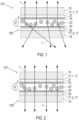
- the composite pane 100 which is designed here, for example, as a windshield of a motor vehicle, comprises a first pane 15, which serves as an outer pane, and a second pane 16 as an inner pane.
- the inner pane is the pane facing the vehicle interior, while the outer pane faces the vehicle surroundings.
- the two panes 15, 16 are made, for example, of soda-lime glass.
- the two disks 15, 16 are firmly connected to one another by a thermoplastic intermediate layer 17.
- the composite pane 100 is equipped with an electro-optical functional element 18 (see also Figures 3 and 4 ), which is, for example, a PDLC functional element.
- the PDLC functional element serves as an electrically controllable sun visor, which is attached in an area above the central viewing area B (as defined in ECE-R43).
- the PDLC functional element is formed by a commercially available PDLC multilayer film, which is embedded in the intermediate layer 17.
- the intermediate layer 17 comprises a total of three thermoplastic composite films, each of which is formed by a thermoplastic film made of PVB with a thickness of, for example, 0.38 mm.
- thermoplastic composite film 17-1 connected to the first disk 15 and a second thermoplastic composite film 17-2 connected to the second disk 16 are shown.
- the intermediate thermoplastic frame film (not shown) has a cutout into which the cut functional element 18 fits precisely. that is, inserted flush on all sides.
- the third thermoplastic composite film thus forms a kind of pas-partout for the functional element 18, which is thus encapsulated all around in thermoplastic material and is thereby protected.
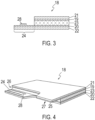
- the electrically controllable functional element 18 is a multilayer film, consisting of an active layer 23 between two surface electrodes 19, 20, and two carrier films 21, 22.
- the active layer 23 contains a polymer matrix with liquid crystals dispersed therein, which depend on the surface electrodes 19 , 20 align the applied electrical voltage S, whereby the optical properties can be regulated.
- the carrier films 21, 22 are made, for example, of PET and have a thickness of, for example, 0.125 mm.
- the carrier films 21, 22 are each provided with a coating of ITO facing the active layer 23 with a thickness of approximately 100 nm, which forms the first surface electrode 19 on the first carrier film 21 and the second surface electrode 20 on the second carrier film 22.
- the two surface electrodes 19, 20 can each be connected to the on-board electrical system via bus conductors and a single flat cable as a connecting cable, which will be explained in more detail below.
- Figure 4 shows a perspective view of the functional element 18 of the connection arrangement 101 with composite disk 100 from Figures 1 and 2 .
- a long side (longitudinal edge) of the functional element 18 is provided with two connection zones 24, 25, which serve for electrical contacting of the associated surface electrode 20, 19.
- the first carrier film 21 and the first surface electrode 19 applied thereto as well as the active layer 23 have a first cutout 26 along the longitudinal edge, which extends to the second carrier film 22 with the second surface electrode 20 applied.
- the second surface electrode 22 is therefore accessible from the side of the active layer (here from above).
- the second carrier film 22 and the second surface electrode 20 form a first connection zone 24 in the area of the first cutout 26.
- the second carrier film 22 and the applied second surface electrode 20 as well as the active layer 23 have a second cutout 27 along the same longitudinal edge extends to the first carrier film 21 and the applied first surface electrode 19.
- the first surface electrode 19 is therefore accessible from the side of the active layer 23 (here from below).
- the first carrier film 21 and the first surface electrode 19 form a second connection zone 25 in the area of the second cutout 27.
- connection zone 24, 25 is provided with a busbar, which is formed here, for example, by a silver-containing screen print.
- a busbar which is formed here, for example, by a silver-containing screen print.
- the two connection zones 24, 25 are arranged laterally offset along the longitudinal edge of the functional element 18 and are designed analogously. The statements for the first connection zone 24 therefore apply in a corresponding manner to the second connection zone 25.
- Figure 3 additionally shows a section vertically through the pane plane in the area of the first connection zone 24, which shows the second surface electrode 20 and the second carrier film 22 as well as the busbar 28 applied thereto.
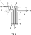
- FIG. 5 a flexible flat cable with an elongated structure, designated overall by the reference number 1, is illustrated in a schematic manner.
- the flat cable 1 is used for common connection to the two connection zones 24, 25.
- the flat cable 1 has a plurality of electrical conductor tracks 2, which are mounted on a carrier substrate 3 made of an electrically insulating material, here for example Polyimide, are applied next to each other.
- the electrical conductor tracks 2 consist of a metallic material, here for example copper, and are applied to the carrier substrate 3 using a printing process.
- the electrical conductor tracks 2 are covered by a cover layer 4, not shown, made of an electrically insulating material, here for example polyimide.
- the carrier substrate and the cover casing 4 together form an insulating casing in which the conductor tracks 2 are embedded.
- the flat cable 1 for example, has a length of 5 cm to 150 cm.
- the carrier substrate 3 and the cover layer 4 each have, for example, a thickness of 10 ⁇ m to 300 ⁇ m.
- the flat cable 1 is flexible and can easily be laminated into the composite pane and led out of it.
- the flexible flat cable 1 has a base section 5 and a strip-shaped section 6 (strip section) connected to the base section 5 (directly), which is arranged at the edge of the base section 5 and protrudes laterally from the base section 5, here for example vertically. It would also be possible for the strip-shaped section 6 to be formed by recessing the front edge 7 of the flat cable 1.
- the flat cable 1 has a first connection area 10 at a first end 8 in the base section 5 and a second connection area 11 in the strip-shaped section 6.
- the two connection areas 10, 11 are formed on the same side of the flat conductor 1 and therefore do not face each other when the strip-shaped section 6 is not folded over.
- the flat cable 1 has a third connection area 12 at its second end 9 in the base section 5.
- the cover layer 4 is removed from the connection areas 10, 11, 12, so that these connection areas 10, 11, 12 are (only) accessible from one side.
- the flat cable 1 is therefore almost completely covered by an insulating sheath made of polyimide and is therefore electrically insulated. Only the connection areas 10, 11, 12 are formed without a cover layer 4. This can be achieved, for example, by a window technology during production or by subsequent removal of the cover layer 4, for example by laser ablation.
- the flat cable 1 here, for example, has eight electrical conductor tracks 2, which are arranged next to one another on the carrier substrate 3. Seven conductor tracks 2 extend from the first connection region 10 of the base section 5 to the third connection region 12 of the base section 5. A conductor track 2 extends from the second connection region 11 of the strip-shaped section 6 to the third connection region 12 of the base section 5. Each conductor track 2 has a contact point 13 at the first end 8 and a contact point 13 'at the second end 9 of the flat cable 1.
- the contact points 13, 13 ' are designed here, for example, as solder contact points.
- the strip-shaped section 6 is elongated and can be folded over due to the flexibility of the flat cable 1.
- Figure 5 shows a situation in which the strip-shaped section 6 is not folded over, ie the surface sections of the carrier substrate 2 in the area of the base section 5 and the strip-shaped section 6, to which the conductor tracks 2 are applied, have the same orientation. This is, for example, the delivery status of the flat cable 1.
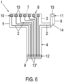
- Figure 6 a situation is shown in which the strip-shaped section 6 is folded over in a folding area 14. In the folding area 14, one side of a part of the strip-shaped section 6 comes to rest on the same side of a further part of the strip-shaped section 6.
- the angle between the extension directions of the strip-shaped section 6 in front of the folding area 14 and after the folding area 14 is here, for example, 90 °, so that the distal part of the strip-shaped section 6, ie the folded over part of the strip-shaped section 6, and the elongated base section 5 in the point in the same direction and are parallel to each other.
- the strip-shaped section 6 is not folded with sharp edges, but with a radius of curvature r of 0.1 mm to 100 mm, which means that damage to the flat conductor 1 and in particular to the conductor track 2 can be avoided.
- the first connection area 10 and the second connection area 11 are arranged on the same side of the flat cable 11. However, when folded over, as in Figure 6 shown, the second connection area 11 is rotated by 180 ° so that the two connection areas 10, 11 face each other, the second connection area 11 being arranged laterally offset from the first connection area 10. It would also be possible for the two connection areas 10, 11 to have a comparison.
- the first connection area 10 and the second connection area 11 thus have a different orientation.
- FIG 7 the electrical connection of the flat cable 1 to the two connection zones 24, 25 of the functional element 18 is illustrated schematically.
- the first connection area 10 of the base section 5 is electrically connected directly to the second connection zone 25.
- the second connection area 11 on the strip-shaped section 6 rotated by 180 ° is electrically connected directly to the first connection zone 24.
- the contact points 13 of the first connection area 10 are soldered to the busbar 28 of the second connection zone 25 from one side (direction), the contact point 13 of the second connection area 11 is soldered to the busbar of the first connection zone 24 from the other side (direction). .
- the flat cable 1 according to the invention thus advantageously enables electrical contacting of both connection zones 24, 25.
- the flat cable 1 is led out of the composite pane 100 with its base section 5, the third connection area 12 being arranged outside the composite pane 100 and being electrically connected to a control device, for example motor vehicle electronics.
- the composite disk 100 with the connected flat cable 1 forms a connection arrangement 101.
- Figure 8 shows a flowchart of a method according to the invention for producing the connection arrangement 101 according to the invention.
- connection arrangement according to the invention advantageously enables simultaneous electrical contacting of two electrically conductive structures, in particular two surface electrodes electro-optical functional element, made possible from two directions.
- the flat cable and the resulting connection arrangement can save material and costs.
- connection arrangement according to the invention is space-saving and easy to integrate into the technical environment.
Description
Die Erfindung betrifft eine Anschlussanordnung mit einem flexiblen Flachkabel mit elektrischen Leiterbahnen, sowie ein Verfahren zu deren Herstellung und deren Verwendung.The invention relates to a connection arrangement with a flexible flat cable with electrical conductor tracks, as well as a method for its production and its use.
Flexible Flachleiter, auch Flachbandleiter oder Folienleiter genannt, werden vielfach im Fahrzeugbau eingesetzt, insbesondere um eine bewegliche, elektrische Kontaktierung bei beschränkten Raumbedingungen zu ermöglichen.Flexible flat conductors, also known as ribbon conductors or foil conductors, are often used in vehicle construction, in particular to enable movable electrical contacting in limited space conditions.
Im Fahrzeugbereich werden Flachleiter beispielsweise zur Kontaktierung von elektrisch funktionellen Schichten in Verbundglasscheiben verwendet. Beispiele finden sich in
Solche Verbundglasscheiben bestehen in der Regel aus mindestens zwei starren Einzelglasscheiben, die durch eine thermoplastische Klebeschicht flächig-adhäsiv miteinander verbunden sind. Die Dicke der Klebeschicht liegt beispielsweise bei 0,76 mm. Zwischen den Einzelglasscheiben befinden sich zusätzlich elektrisch funktionelle Schichten wie Heizbeschichtungen und/oder Antennenelemente, die mit einem Flachleiter verbunden sind. Ein hierfür geeigneter Flachleiter weist lediglich eine Gesamtdicke von 0,3 mm auf. Derart dünne Flachleiter können ohne Schwierigkeiten zwischen den Einzelglasscheiben in der thermoplastischen Klebeschicht eingebettet werden.Such laminated glass panes usually consist of at least two rigid individual glass panes, which are adhesively connected to one another using a thermoplastic adhesive layer. The thickness of the adhesive layer is, for example, 0.76 mm. Between the individual glass panes there are additional electrically functional layers such as heating coatings and/or antenna elements that are connected to a flat conductor. A flat conductor suitable for this only has a total thickness of 0.3 mm. Such thin flat conductors can be embedded between the individual glass panes in the thermoplastic adhesive layer without any difficulty.
Der Einsatz von Flachleitern zur Kontaktierung von elektrisch funktionellen Schichten ist nicht nur auf den Fahrzeugbereich beschränkt. Wie aus
Bekannt ist auch die Verwendung von Flachleitern bei Verbundscheiben mit elektrooptischen Funktionselementen. Hierbei handelt es sich um flächenhafte Strukturen mit elektrisch regelbaren optischen Eigenschaften einer aktiven Schicht. Das heißt, die optischen Eigenschaften der aktiven Schicht und insbesondere deren Transparenz, Streuverhalten oder Leuchtkraft sind durch eine elektrische Spannung steuerbar. Beispiele für elektrooptische Funktionselemente sind SPD-Funktionselemente (SPD = Suspended Particle Device), die beispielsweise aus
Elektrooptische Funktionselemente, wie SPD- oder PDLC-Funktionselemente, sind als Mehrschichtfolie kommerziell erhältlich, wobei die aktive Schicht zwischen zwei Flächenelektroden angeordnet ist, die zum Anlegen einer Spannung zur Steuerung der aktiven Schicht dienen. In aller Regel sind die beiden Flächenelektroden zwischen zwei Trägerfolien, typischerweise aus PET, angeordnet. Kommerziell erhältliche Mehrschichtfolien werden zudem beidseitig mit einer Schutzfolie aus Polypropylen oder Polyethylen abgedeckt, welche dazu dienen, die Trägerfolien vor Verschmutzungen oder Verkratzungen zu schützen.Electro-optical functional elements, such as SPD or PDLC functional elements, are commercially available as a multilayer film, with the active layer being arranged between two surface electrodes which are used to apply a voltage to control the active layer. As a rule, the two surface electrodes are arranged between two carrier films, typically made of PET. Commercially available multilayer films are also covered on both sides with a protective film made of polypropylene or polyethylene, which serves to protect the carrier films from dirt or scratches.
Bei der Herstellung der Verbundscheibe wird das Funktionselement in der gewünschten Größe und Form aus der Mehrschichtfolie ausgeschnitten und zwischen die Folien einer Zwischenschicht eingelegt, mittels derer zwei Glasscheiben miteinander zur Verbundscheibe laminiert werden.When producing the composite pane, the functional element is cut out of the multilayer film in the desired size and shape and inserted between the films of an intermediate layer, by means of which two glass panes are laminated together to form the composite pane.
Eine typische Anwendung sind Windschutzscheiben mit elektrisch regelbaren Sonnenblenden, welche beispielsweise aus
In der Regel wird vom Scheibenhersteller eine Scheibe mit einem kompletten Anschlusselement und einem Anschlussbereich zum werkzeuglosen Anschluss an eine weitere Steuerungselektrik gefordert.As a rule, the window manufacturer requires a window with a complete connection element and a connection area for tool-free connection to additional control electronics.
Die elektrische Kontaktierung von elektrooptischen Funktionselementen erfolgt üblicherweise über Sammelleiter (auch als "Busbars" bezeichnet), die im Randbereich des Funktionselementes auf die Flächenelektroden aufgebracht sind und diese elektrisch leitend kontaktieren. Durch Verbinden der Sammelleiter mit einer externen Spannungsquelle, typischer Weise über an den Sammelleitern angebrachte Flachleiter (z.B. FFC = Flexible Flat Cable), wird eine Spannung an den Flächenelektroden angelegt und die aktive Schicht des Funktionselementes geschaltet.The electrical contacting of electro-optical functional elements usually takes place via busbars (also referred to as “busbars”), which are applied to the surface electrodes in the edge region of the functional element and contact them in an electrically conductive manner. By connecting the busbars to an external voltage source, typically via flat conductors attached to the busbars (e.g. FFC = Flexible Flat Cable), a voltage is applied to the surface electrodes and the active layer of the functional element is switched.
Für komplexere Steueraufgaben werden auch flexible Flachkabel eingesetzt, die mit einer Mehrzahl elektrischer Leiterbahnen versehen sind. Die elektrischen Leiterbahnen sind sehr dünn mit Dicken beispielsweise im Bereich von 0,03 mm bis 0,1 mm und bestehen beispielsweise aus Kupfer, das sich bewährt hat, da es eine gute elektrische Leitfähigkeit sowie eine gute Verarbeitbarkeit besitzt und die Materialkosten gleichzeitig niedrig sind.For more complex control tasks, flexible flat cables are also used, which are provided with a number of electrical conductor tracks. The electrical conductor tracks are very thin with thicknesses, for example, in the range of 0.03 mm to 0.1 mm and are made, for example, of copper, which has proven itself because it has good electrical conductivity and good processability and the material costs are low at the same time.
Bei der Herstellung der flexiblen Flachkabel werden die elektrischen Leiterbahnen auf ein Trägersubstrat aus Kunststoff aufgebracht, beispielsweise im Druckverfahren, und anschließend mit einer Deckschicht aus Kunststoff abgedeckt. Alternativ werden die elektrischen Leiterbahnen als Metallstreifen aus Metallfolien vorgefertigt und beidseitig mit einem Kunststoffmaterial laminiert. In beiden Fällen sind die elektrischen Leiterbahnen mechanisch stabilisiert und in eine Isolationshülle eingebettet, so dass sie gegen die äußere Umgebung elektrisch isoliert sind.When producing the flexible flat cables, the electrical conductor tracks are applied to a plastic carrier substrate, for example using a printing process, and then covered with a plastic cover layer. Alternatively, the electrical conductor tracks are prefabricated as metal strips made of metal foil and laminated on both sides with a plastic material. In both cases, the electrical conductor tracks are mechanically stabilized and embedded in an insulating sleeve so that they are electrically insulated from the external environment.
Werden die elektrischen Leiterbahnen auf ein Trägersubstrat aufgebracht, sind sie nur von der Deckschicht her zugänglich, da nur diese entfernt werden kann, ohne die elektrischen Leiterbahnen zu beschädigen. Solche flexiblen Flachkabel haben deshalb nur eine einzige Kontaktierungsseite, welche der Seite der Deckschicht entspricht. Sollen zwei einander gegenüberliegende elektrische Strukturen, wie die Flächenelektroden eines elektrooptischen Funktionselements, aus zwei entgegengesetzten Richtungen kontaktiert werden, sind zwei flexible Flachkabel erforderlich, von denen eines um 180° gegen das andere gedreht ist, wobei die Flachkabel jeweils mit ihrer Kontaktierungsseite auf die elektrische Struktur aufgesetzt werden.If the electrical conductor tracks are applied to a carrier substrate, they are only accessible from the cover layer, since only this can be removed without damaging the electrical conductor tracks. Such flexible flat cables therefore only have a single contacting side, which corresponds to the side of the cover layer. If two opposing electrical structures, such as the surface electrodes of an electro-optical functional element, are to be contacted from two opposite directions, two flexible flat cables are required, one of which is rotated by 180° relative to the other, with the flat cables each facing the electrical structure with its contacting side be set up.
Die Patentanmeldung
Die Aufgabe der vorliegenden Erfindung besteht darin, eine verbesserte Anschlussanordnung mit einem flexiblen Flachkabel bereitzustellen, wobei das Flachkabel zur gemeinsamen Kontaktierung von einander gegenüberliegenden elektrischen Strukturen aus zwei entgegengesetzten Richtungen geeignet ist und gleichzeitig einfach und kostengünstig hergestellt werden kann.The object of the present invention is to provide an improved connection arrangement with a flexible flat cable, the flat cable for common contacting of opposite ones electrical structures from two opposite directions and at the same time can be manufactured easily and inexpensively.
Diese und weitere Aufgaben werden nach dem Vorschlag der Erfindung durch eine Anschlussanordnung mit einem flexiblen Flachkabel gemäß Anspruch 1 gelöst. Bevorzugte Ausführungen gehen aus den Unteransprüchen hervor. Ein Verfahren zur deren Herstellung sowie die Verwendung der erfindungsgemäßen Anschlussanordnung mit flexiblem Flachkabel gehen aus den nebengeordneten Ansprüchen hervor.These and other tasks are solved according to the proposal of the invention by a connection arrangement with a flexible flat cable according to
Die Erfindung betrifft eine Anschlussanordnung mit einem flexiblen Flachkabel, welche umfasst:
- eine Verbundscheibe aus einer ersten Scheibe und einer zweiten Scheibe, die mit einer Zwischenschicht verbunden sind,
- zwei elektrisch leitfähige Strukturen, die zwischen der ersten Scheibe und der zweiten Scheibe angeordnet sind, und
- ein flexibles Flachkabel, dessen erster Anschlussbereich mit der einen elektrisch leitfähigen Struktur und dessen zweiter Anschlussbereich mit der anderen elektrisch leitfähigen Struktur elektrisch leitend und insbesondere galvanisch verbunden sind, wobei der Flachleiter aus der Verbundscheibe herausgeführt ist und der dritte Anschlussbereich außerhalb der Verbundscheibe angeordnet ist.
- a composite pane consisting of a first pane and a second pane, which are connected to an intermediate layer,
- two electrically conductive structures arranged between the first disk and the second disk, and
- a flexible flat cable, the first connection area of which is electrically conductively and in particular galvanically connected to the one electrically conductive structure and the second connection area of which is electrically connected to the other electrically conductive structure, the flat conductor being led out of the composite pane and the third connection area being arranged outside the composite pane.
Das flexible Flachkabel umfasst eine Mehrzahl elektrischer Leiterbahnen (Leiterstreifen), an denen zumindest auf einer Seite eine elektrische Isolationsschicht aus Kunststoff angeordnet ist. Vorteilhaft sind die elektrischen Leiterbahnen von einer elektrischen Isolationshülle ummantelt. Das flexible Flachkabel dient zum elektrischen Anschluss an mindestens zwei elektrische Strukturen, die vorzugsweise einander gegenüberliegend angeordnet sind und von zwei entgegengesetzten Seiten (Richtungen) her elektrisch kontaktiert werden sollen.The flexible flat cable comprises a plurality of electrical conductor tracks (conductor strips), on which an electrical insulation layer made of plastic is arranged at least on one side. The electrical conductor tracks are advantageously encased in an electrical insulation cover. The flexible flat cable is used for electrical connection to at least two electrical structures, which are preferably arranged opposite one another and are to be electrically contacted from two opposite sides (directions).
Das flexible Flachkabel ist ein flächiger Körper mit zwei gegenüberliegenden Seiten, der wahlweise in eine ebene oder gekrümmte Form gebracht werden kann. Im ebenen (d.h. nicht-gekrümmten) Zustand ist der Flachleiter in einer Ebene angeordnet. Das flexible Flachkabel ist generell länglich ausgebildet und weist entlang seiner Erstreckungsrichtung zwei Enden auf.The flexible flat cable is a flat body with two opposite sides that can be made into a flat or curved shape. In the flat (ie non-curved) state, the flat conductor is arranged in a plane. The flexible flat cable is generally elongated and has two ends along its direction of extension.
Die elektrischen Leiterbahnen sind zumindest abschnittsweise nebeneinander liegend angeordnet. Jede elektrische Leiterbahn kann an zwei entlang der Leiterbahn voneinander beabstandeten Kontaktstellen elektrisch kontaktiert werden. Die Kontaktstellen sind Bereiche der Leiterbahnen, an denen eine elektrische Kontaktierung möglich ist. In der einfachsten Ausgestaltung handelt es sich hierbei um zugängliche Bereiche der elektrischen Leiterbahnen.The electrical conductor tracks are arranged next to one another, at least in sections. Each electrical conductor track can be electrically contacted at two contact points spaced apart along the conductor track. The contact points are areas of the conductor tracks where electrical contact is possible. In the simplest embodiment, these are accessible areas of the electrical conductor tracks.
Das Flachkabel ist ein längliches elektrisches Bauteil mit mehreren elektrischen Leiterbahnen, dessen Breite deutlich größer ist als die Dicke. Das Flachkabel ist derart dünn ausgebildet (d.h. die Dicke ist derart gering), dass es flexibel und biegbar ist.The flat cable is an elongated electrical component with several electrical conductor tracks, the width of which is significantly larger than the thickness. The flat cable is so thin (i.e. the thickness is so small) that it is flexible and bendable.
Das flexible Flachkabel umfasst einen ersten Anschlussbereich, der sich entlang der Erstreckungsrichtung des Flachkabels an einem ersten Ende und auf einer ersten Seite des Flachkabels befindet. Insbesondere befindet sich der erste Anschlussbereich nur auf der ersten Seite des Flachkabels. Der erste Anschlussbereich weist eine Kontaktstelle mindestens einer der elektrischen Leiterbahnen auf.The flexible flat cable includes a first connection area, which is located along the extension direction of the flat cable at a first end and on a first side of the flat cable. In particular, the first connection area is only on the first side of the flat cable. The first connection area has a contact point of at least one of the electrical conductor tracks.
Das flexible Flachkabel umfasst weiterhin mindestens einen zweiten Anschlussbereich, der sich auch am ersten Ende (d.h. am selben Ende wie der erste Anschlussbereich) und auf der ersten Seite (d.h. auf derselben Seite wie der erste Anschlussbereich) des Flachkabels befindet. Insbesondere befindet sich der zweite Anschlussbereich nur auf der ersten Seite des Flachkabels. Der mindestens eine zweite Anschlussbereich weist eine Kontaktstelle mindestens einer der elektrischen Leiterbahnen auf.The flexible flat cable further comprises at least a second connection area, which is also located at the first end (i.e. on the same end as the first connection area) and on the first side (i.e. on the same side as the first connection area) of the flat cable. In particular, the second connection area is only on the first side of the flat cable. The at least one second connection area has a contact point of at least one of the electrical conductor tracks.
Ferner umfasst das flexible Flachkabel mindestens einen dritten Anschlussbereich mit Kontaktstellen der Leiterbahnen an einem zweiten Ende des Flachkabels in Erstreckungsrichtung des Flachkabels.Furthermore, the flexible flat cable comprises at least a third connection area with contact points of the conductor tracks at a second end of the flat cable in the extension direction of the flat cable.
Die Anschlussbereiche des Flachkabels dienen zum elektrischen Kontaktieren der Leiterbahnen, zu welchem Zweck die Isolationshülle zumindest an den Kontaktstellen nicht vorhanden oder entfernt ist, so dass die Leiterbahnen zugänglich sind. Wesentlich hierbei ist, dass sich die Kontaktstellen der Leiterbahnen im ersten Anschlussbereich und zweiten Anschlussbereich auf einer selben Seite des Flachkabels befinden. Dies ist insbesondere dann typischer Weise der Fall, wenn die elektrischen Leiterbahnen auf ein Trägersubstrat aufgebracht sind, beispielsweise im Druckverfahren, so dass nur Öffnungen (Durchbrechungen) der Deckschicht ausgebildet werden können, ohne die Leiterbahnen zu beschädigen.The connection areas of the flat cable are used to electrically contact the conductor tracks, for which purpose the insulation sleeve is not present or removed, at least at the contact points, so that the conductor tracks are accessible. What is important here is that the contact points of the conductor tracks in the first connection area and second connection area are on the same side of the flat cable. This is particularly typically the case when the electrical conductor tracks are applied to a carrier substrate, for example Printing process so that only openings (breakthroughs) in the cover layer can be formed without damaging the conductor tracks.
Das flexible Flachkabel weist einen den ersten Anschlussbereich enthaltenden Basisabschnitt und mindestens einen mit der Basisabschnitt verbundenen streifenförmigen Abschnitt (Streifenabschnitt) auf, welcher den zweiten Anschlussbereich aufweist. Hierbei ist der streifenförmige Abschnitt als Teil des flexiblen Flachkabels so umfaltbar oder umgefaltet, dass der zweite Anschlussbereich dem ersten Anschlussbereich zugewandt ist. Der mindestens eine streifenförmige Abschnitt ist vorzugsweise länglich ausgebildet. Ebenso ist der Basisabschnitt vorzugsweise länglich ausgebildet.The flexible flat cable has a base section containing the first connection area and at least one strip-shaped section (strip section) connected to the base section and having the second connection area. Here, the strip-shaped section can be folded or folded over as part of the flexible flat cable in such a way that the second connection area faces the first connection area. The at least one strip-shaped section is preferably elongated. Likewise, the base section is preferably elongated.
Der erste Anschlussbereich und der zweite Anschlussbereich sind auf derselben Seite des Flachkabels angeordnet, d.h. die beiden Anschlussbereiche sind einander nicht zugewandt, wenn der streifenförmige Abschnitt nicht umgefaltet ist. Vielmehr sind die beiden Anschlussbereiche auf derselben Seite des Flachkabels angeordnet. Im umgefalteten Zustand hingegen, ist der zweite Anschlussbereich gegenüber dem nicht-gefalteten Zustand um 180° gedreht, so dass die beiden Anschlussbereiche einander zugewandt sind. Sowohl im nicht-gefalteten Zustand wie auch im umgefalteten Zustand sind die Flächennormale des Flachkabels im ersten Anschlussbereich und die Flächennormale des Flachkabels im zweiten Anschlussbereich zueinander parallel.The first connection area and the second connection area are arranged on the same side of the flat cable, i.e. the two connection areas do not face each other when the strip-shaped section is not folded over. Rather, the two connection areas are arranged on the same side of the flat cable. In the folded state, however, the second connection area is rotated by 180° compared to the unfolded state, so that the two connection areas face each other. Both in the unfolded state and in the folded state, the surface normals of the flat cable in the first connection area and the surface normals of the flat cable in the second connection area are parallel to one another.
In vorteilhafter Weise können auf diese Weise einander gegenüberliegende elektrische Strukturen, insbesondere zwei Flächenelektroden eines elektrooptischen Funktionselements, durch ein und dasselbe Flachkabel elektrisch kontaktiert werden. Eine elektrische Kontaktierung ist in vorteilhafter Weise auch von zwei Seiten her, d.h. aus zwei entgegengesetzten Richtungen, möglich. Im Unterschied zum Stand der Technik kann auf die Verwendung von zwei separaten Flachkabeln verzichtet werden, wodurch Material und Kosten eingespart werden können.In an advantageous manner, opposing electrical structures, in particular two surface electrodes of an electro-optical functional element, can be electrically contacted by one and the same flat cable. Electrical contacting is also advantageously possible from two sides, i.e. from two opposite directions. In contrast to the prior art, there is no need to use two separate flat cables, which saves material and costs.
Bei einer vorteilhaften Ausgestaltung des flexiblen Flachkabels ist der den zweiten Anschlussbereich aufweisende, streifenförmige Abschnitt randständig am Basisabschnitt angeordnet. Dies ermöglicht eine besonders einfache Handhabung und Faltung des streifenförmigen Abschnitts zur Kontaktierung der zugehörigen elektrischen Struktur. Vorteilhaft kann es sein, wenn der streifenförmige Abschnitt vom Basisabschnitt seitlich absteht, wobei die Erstreckungsrichtung des streifenförmigen Abschnitts verschieden ist von einer Erstreckungsrichtung des Basisabschnitts. Beispielsweise steht der streifenförmige Abschnitt im rechten Winkel vom Basisabschnitt ab.In an advantageous embodiment of the flexible flat cable, the strip-shaped section having the second connection area is arranged at the edge of the base section. This enables particularly easy handling and folding of the strip-shaped section for contacting the associated electrical structure. It can be advantageous if the strip-shaped section from Base section projects laterally, the direction of extension of the strip-shaped section being different from an extension direction of the base section. For example, the strip-shaped section projects at right angles from the base section.
Gemäß einer weiteren Ausgestaltung des flexiblen Flachkabels ist der streifenförmige Abschnitt so umfaltbar oder umgefaltet, dass der zweite Anschlussbereich seitlich versetzt zum ersten Anschlussbereich angeordnet ist, d.h. die beiden Anschlussbereiche haben keine Gegenüberstellung (in Sicht senkrecht durch die Ebene des Flachkabels im nicht-gekrümmten Zustand). Alternativ ist es gleichermaßen möglich, dass der streifenförmige Abschnitt so umfaltbar oder umgefaltet ist, dass der zweite Anschlussbereich in Gegenüberstellung zum ersten Anschlussbereich angeordnet ist.According to a further embodiment of the flexible flat cable, the strip-shaped section can be folded or folded over in such a way that the second connection area is arranged laterally offset from the first connection area, i.e. the two connection areas have no juxtaposition (in view vertically through the plane of the flat cable in the non-curved state) . Alternatively, it is equally possible for the strip-shaped section to be folded or folded over in such a way that the second connection area is arranged opposite the first connection area.
Gemäß einer weiteren Ausgestaltung des flexiblen Flachkabels ist zwischen dem Basisabschnitt und dem streifenförmigen Abschnitt eine Vertiefung einer Vorderkante des Flachkabels ausgebildet. Diese Maßnahme ermöglicht eine besonders einfache Herstellung des streifenförmigen Abschnitts, insbesondere aus herkömmlichen Flachkabeln.According to a further embodiment of the flexible flat cable, a depression in a front edge of the flat cable is formed between the base section and the strip-shaped section. This measure enables a particularly simple production of the strip-shaped section, in particular from conventional flat cables.
Gemäß einer Ausgestaltung des Flachkabels sind die elektrischen Leiterbahnen auf ein elektrisch isolierendes Trägersubstrat aufgebracht und somit mit dem Trägersubstrat fest verbunden. Beispielsweise ist das Trägersubstrat mit den elektrischen Leiterbahnen beschichtet, insbesondere im Druckverfahren, beispielsweise Siebdruckverfahren. Zudem sind die elektrischen Leiterbahnen durch eine elektrisch isolierende Deckschicht abgedeckt. Das Trägersubstrat und die Deckschicht formen gemeinsam eine Isolationshülle, welche die elektrischen Leiterbahnen umhüllt. Bei dieser Ausgestaltung weisen der erste Anschlussbereich und der zweite Anschlussbereich vorzugsweise nur auf der vom Trägersubstrat abgewandten Seite zumindest an den Kontaktstellen keine Isolationsschicht auf, d.h. die Deckschicht ist dort entfernt, z.B. mit einer oder mehreren Öffnungen (Durchbrechungen) versehen.According to one embodiment of the flat cable, the electrical conductor tracks are applied to an electrically insulating carrier substrate and are thus firmly connected to the carrier substrate. For example, the carrier substrate is coated with the electrical conductor tracks, in particular using a printing process, for example screen printing. In addition, the electrical conductor tracks are covered by an electrically insulating cover layer. The carrier substrate and the cover layer together form an insulating shell that envelops the electrical conductor tracks. In this embodiment, the first connection area and the second connection area preferably only have no insulation layer on the side facing away from the carrier substrate, at least at the contact points, i.e. the cover layer is removed there, for example provided with one or more openings (breakthroughs).
Gemäß einer weiteren Ausgestaltung des Flachkabels sind die elektrischen Leiterbahnen vorgefertigt, beispielsweise als Streifen aus einer Metallfolie, und zwischen zwei Isolationsschichten aus elektrisch isolierendem Material laminiert, welche gemeinsam eine Isolationshülle formen, welche die elektrischen Leiterbahnen einbettet. Bei dieser Ausgestaltung weisen der erste Anschlussbereich und der zweite Anschlussbereich vorzugsweise nur auf einer selben Seite zumindest an den Kontaktstellen keine Isolationsschicht auf.According to a further embodiment of the flat cable, the electrical conductor tracks are prefabricated, for example as strips made of a metal foil, and laminated between two insulation layers made of electrically insulating material, which together form an insulating shell that embeds the electrical conductor tracks. In this embodiment, the first connection area and the second connection area preferably only have no insulation layer on the same side, at least at the contact points.
Die elektrischen Leiterbahnen enthalten oder bestehen vorzugsweise aus einem metallischen Material, beispielsweise Kupfer, Aluminium, Edelstahl, Zinn, Gold, Silber oder Legierungen hieraus. Werden die elektrischen Leiterbahnen als Streifen aus einer Metallfolie hergestellt, kann das Metall abschnittsweise oder vollständig verzinnt sein. Dies ist besonders vorteilhaft um eine gute Lötbarkeit bei gleichzeitigem Korrosionsschutz zu erzielen. Zudem wird die Kontaktierung mit einem elektrisch leitfähigen Klebstoff verbessert.The electrical conductor tracks preferably contain or consist of a metallic material, for example copper, aluminum, stainless steel, tin, gold, silver or alloys thereof. If the electrical conductor tracks are made as strips of metal foil, the metal can be tinned in sections or completely. This is particularly advantageous in order to achieve good solderability and simultaneous corrosion protection. In addition, the contact is improved with an electrically conductive adhesive.
Gemäß einer Ausgestaltung weisen die elektrischen Leiterbahnen eine Dicke von 10 µm bis 300 µm, bevorzugt von 30 µm bis 250 µm und insbesondere von 50 µm bis 150 µm auf. Derart dünne Leiter sind besonders flexibel und können beispielsweise gut in Verbundscheiben einlaminiert und aus diesen herausgeführt werden.According to one embodiment, the electrical conductor tracks have a thickness of 10 μm to 300 μm, preferably from 30 μm to 250 μm and in particular from 50 μm to 150 μm. Such thin conductors are particularly flexible and can, for example, be easily laminated into composite panes and led out of them.
Gemäß einer Ausgestaltung weisen die elektrischen Leiterbahnen eine Breite von 0,1 mm bis 100 mm, insbesondere von 1 mm bis 50 mm und insbesondere von 10 mm bis 30 mm auf. Derartige Breiten sind besonders geeignet um in Verbindung mit den oben genannten Dicken eine ausreichende Stromtragefähigkeit zu erzielen.According to one embodiment, the electrical conductor tracks have a width of 0.1 mm to 100 mm, in particular from 1 mm to 50 mm and in particular from 10 mm to 30 mm. Such widths are particularly suitable for achieving sufficient current-carrying capacity in conjunction with the thicknesses mentioned above.
Die Breite des Flachkabels kann konstant sein oder variieren. Insbesondere kann das Flachkabel im Bereich des ersten Anschlusselement, des zweiten Anschlusselements und/oder des dritten Anschlusselements und beispielsweise nur im Bereich des dritten Anschlusselements verbreitert sein.The width of the flat cable can be constant or vary. In particular, the flat cable can be widened in the area of the first connection element, the second connection element and/or the third connection element and, for example, only in the area of the third connection element.
In einer vorteilhaften Ausgestaltung des Flachkabels weist dieses eine Länge von 5 cm bis 150 cm, bevorzugt von 10 cm bis 100 cm und insbesondere von 50 cm bis 90 cm auf. Es versteht sich, dass die Länge, Breite und Dicke des Flachkabels an die Anforderungen des jeweiligen Einzelfalls angepasst werden können.In an advantageous embodiment of the flat cable, it has a length of 5 cm to 150 cm, preferably 10 cm to 100 cm and in particular 50 cm to 90 cm. It is understood that the length, width and thickness of the flat cable can be adapted to the requirements of each individual case.
Bei einem erfindungsgemäßen Flachkabel definiert die Richtung der Länge die Erstreckungsrichtung. Die Längen- und die Breitenrichtung spannen die erste Seite und die, der ersten Seite gegenüberliegende, zweite Seite auf. Die erste Seite kann beispielsweise auch Oberseite und die zweite Seite kann auch Unterseite des Flachkabels genannt werden. Das erste Ende und das zweite Ende sind die einander gegenüberliegenden Enden (Endbereiche) des Flachleiters in ErstreckungsrichtungIn a flat cable according to the invention, the direction of the length defines the direction of extension. The length and width directions span the first page and the second page opposite the first page. For example, the first side can also be called the top side and the second side can also be called the bottom side of the flat cable. The first end and the second end are the opposite ends (end regions) of the flat conductor in the extension direction
Das flexible Flachkabel weist auf einer oder beiden Seiten eine Isolationsschicht auf, die beispielsweise in Form einer Isolationsfolie ausgebildet ist. Die Isolationsschicht ist mit den elektrischen Leiterbahnen fest verbunden und beispielsweise verklebt. Die Isolationsschicht enthält bevorzugt Polyimid oder Polyesther, besonders bevorzugt Polyethylenterephtalat (PET) oder Polyethylennapthalat(PEN) oder besteht daraus. Die Isolationsschicht kann auch aus einem elektrisch isolierenden Lack, bevorzugt einem Polymerlack, bestehen. Die Isolationsschicht kann auch thermoplastische Kunststoffe und Elastomere wie Polyamid, Polyoxymethylen, Polybutylenterephthalat oder Ethylen-Propylen-Dien-Kautschuk enthalten oder daraus bestehen. Alternativ können Vergusswerkstoffe wie Acrylat- oder Epoxidharzsysteme als Isolationsschicht verwendet werden.The flexible flat cable has an insulating layer on one or both sides, which is designed, for example, in the form of an insulating film. The insulation layer is firmly connected to the electrical conductor tracks and, for example, glued. The insulation layer preferably contains or consists of polyimide or polyester, particularly preferably polyethylene terephthalate (PET) or polyethylene naphthalate (PEN). The insulation layer can also consist of an electrically insulating varnish, preferably a polymer varnish. The insulation layer can also contain or consist of thermoplastics and elastomers such as polyamide, polyoxymethylene, polybutylene terephthalate or ethylene-propylene-diene rubber. Alternatively, potting materials such as acrylate or epoxy resin systems can be used as an insulation layer.
Die Isolationsschicht weist bevorzugt eine Dicke von 10 µm bis 300 µm, besonders bevorzugt von 25 µm bis 200 µm und insbesondere von 60 µm bis 150 µm auf. Die Isolationsschicht ist beispielsweise über eine Klebstoffschicht mit den Leiterbahnen verklebt. Die Dicke der Klebstoffschicht beträgt beispielsweise von 10 µm bis 150 µm und besonders bevorzugt von 50 µm bis 75 µm. Derartige Isolationsschichten sind besonders dazu geeignet, die Leiterbahnen elektrisch zu isolieren und mechanisch zu stabilisieren sowie vor mechanischen Beschädigungen und Korrosion zu schützen.The insulation layer preferably has a thickness of 10 µm to 300 µm, particularly preferably 25 µm to 200 µm and in particular 60 µm to 150 µm. The insulation layer is bonded to the conductor tracks, for example via an adhesive layer. The thickness of the adhesive layer is, for example, from 10 μm to 150 μm and particularly preferably from 50 μm to 75 μm. Such insulation layers are particularly suitable for electrically insulating and mechanically stabilizing the conductor tracks and protecting them from mechanical damage and corrosion.
In einer vorteilhaften Ausgestaltung des Flachkabels sind die Leiterbahnen vollständig von einer Isolationshülle ummantelt, d.h. auf beiden Seiten des Flachkabels befindet sich eine Isolationsschicht, wobei die beiden Isolationsschichten gemeinsam die Isolationshülle bilden. Die Isolationshülle kann insbesondere aus dem vorstehend genannten Trägersubstrat und der Deckschicht bestehen. Die Isolationshülle kann auch durch beidseitiges Laminieren der Leiterbahnen mit zwei Isolationsschichten geformt werden.In an advantageous embodiment of the flat cable, the conductor tracks are completely covered by an insulating sheath, i.e. there is an insulating layer on both sides of the flat cable, with the two insulating layers together forming the insulating sheath. The insulating sleeve can in particular consist of the aforementioned carrier substrate and the cover layer. The insulation sleeve can also be formed by laminating the conductor tracks on both sides with two layers of insulation.
Derartige Flachkabel mit mindestens einer Isolationsschicht sind derart dünn, dass sie ohne Schwierigkeiten zwischen den einzelnen Scheiben in der thermoplastischen Zwischenschicht einer Verbundscheibe eingebettet und aus dieser herausgeführt werden können. Das Flachkabel eignet sich besonders zur Kontaktierung von elektrisch leitfähigen Strukturen in Verbundscheiben, insbesondere von gegenüberliegenden Flächenelektroden eines elektrooptischen Funktionselements.Such flat cables with at least one insulation layer are so thin that they can be easily moved between the individual panes in the thermoplastic Intermediate layer of a composite pane can be embedded and led out of it. The flat cable is particularly suitable for contacting electrically conductive structures in composite panes, in particular opposing surface electrodes of an electro-optical functional element.
In einer vorteilhaften Ausgestaltung des Flachkabels weist das Flachkabel im ersten Anschlussbereich, im zweiten Anschlussbereich und im dritten Anschlussbereich keine Isolationsschicht oder eine andere elektrische Isolierung auf. Dies ermöglicht die einfache elektrische und insbesondere galvanische Kontaktierung des Flachkabels. Es versteht sich, dass die Anschlussbereiche durch eine elektrisch leitfähige Beschichtung, wie eine Verzinnung, oder eine elektrisch nicht leitfähige Schicht, wie ein Lötlack, vor Korrosion geschützt sein können. Diese Schutzschicht wird üblicherweise erst bei der elektrischen Kontaktierung entfernt, verbrannt oder anderweitig durchdrungen, um einen elektrischen Kontakt zu ermöglichen.In an advantageous embodiment of the flat cable, the flat cable has no insulation layer or other electrical insulation in the first connection area, in the second connection area and in the third connection area. This enables simple electrical and, in particular, galvanic contacting of the flat cable. It goes without saying that the connection areas can be protected from corrosion by an electrically conductive coating, such as tin plating, or an electrically non-conductive layer, such as soldering varnish. This protective layer is usually only removed, burned or otherwise penetrated during electrical contacting in order to enable electrical contact.
Isolationsfreie Anschlussbereiche lassen sich durch Fenstertechniken bei der Herstellung oder durch nachträgliches Entfernen, beispielsweise durch Laserablation oder mechanisches Abtragen, herstellen. Bei der Fenstertechnik werden die Leiterbahnen auf einem Trägersubstrat durch eine Isolationsschicht (Deckschicht) mit entsprechenden Ausnehmungen (Fenstern) in den Anschlussbereichen beschichtet, beispielsweise beklebt oder laminiert. Alternativ werden die Leiterbahnen beidseitig laminiert, wobei eine Isolationsschicht entsprechende Ausnehmungen in den Anschlussbereichen aufweist. Beim nachträglichen Entfernen können entsprechende Ausnehmungen in den Anschlussbereichen in die Deckschicht eingebracht werden, wenn die Leiterbahnen auf ein Trägersubstrat aufgebracht wurden. Bei laminierten Flachkabeln können Ausnehmungen in den Anschlussbereichen in eine Isolationsschicht eingebracht werden.Insulation-free connection areas can be created using window techniques during production or by subsequent removal, for example by laser ablation or mechanical removal. In window technology, the conductor tracks on a carrier substrate are coated, for example glued or laminated, by an insulating layer (cover layer) with corresponding recesses (windows) in the connection areas. Alternatively, the conductor tracks are laminated on both sides, with an insulation layer having corresponding recesses in the connection areas. When subsequently removed, corresponding recesses can be made in the connection areas in the cover layer if the conductor tracks have been applied to a carrier substrate. For laminated flat cables, recesses can be made in an insulation layer in the connection areas.
Die Anschlussbereiche sind ihrer jeweiligen Verwendung nach ausgebildet. In einer vorteilhaften Ausgestaltung sind die Kontaktstellen als Lötkontaktstellen ausgebildet.The connection areas are designed according to their respective use. In an advantageous embodiment, the contact points are designed as solder contact points.
In einer vorteilhaften Ausgestaltung des Flachkabels sind im ersten Anschlussbereich, im zweiten Anschlussbereich und/oder im dritten Anschlussbereich jeweils eine oder mehrere Durchbrechungen der Isolationsschicht vorgesehen. Die Durchbrechung erstreckt sich dabei vollständig auf die Leiterbahn, d.h. sie bildet einen materialfreien Durchgang auf die Leiterbahn.In an advantageous embodiment of the flat cable, one or more openings in the insulation layer are provided in the first connection area, in the second connection area and/or in the third connection area. The breakthrough extends completely onto the conductor track, ie it forms a material-free passage onto the conductor track.
Das Flachkabel ist in dem mindestens einen streifenförmigen Abschnitt an mindestens einer Stelle (Faltbereich) umgefaltet. Das bedeutet, dass der streifenförmige Abschnitt zwischen dem Basisabschnitt und dem zweiten Anschlussbereich derart aus seiner Erstreckungsebene angehoben und herumgeführt ist, dass ein Teil des streifenförmigen Abschnitts mit einer Seite einem weiteren Teil des streifenförmigen Abschnitts auf derselben Seite zugewandt ist. Die Erstreckungsrichtung des streifenförmigen Abschnitts weicht durch die Umfaltung von seiner Erstreckungsrichtung vor der Umfaltung ab.The flat cable is folded over at at least one point (folding area) in the at least one strip-shaped section. This means that the strip-shaped section between the base section and the second connection region is lifted out of its plane of extension and guided around in such a way that a part of the strip-shaped section has one side facing a further part of the strip-shaped section on the same side. The direction of extension of the strip-shaped section deviates from its direction of extension before the folding due to the folding.
In einer vorteilhaften Ausgestaltung des Flachkabels erfolgt die Faltung um einen Winkel α (alpha). Der Winkel α gibt dabei die Abweichung der Erstreckungsrichtung des Teils des streifenförmigen Abschnitts nach dem mindestens einen Faltbereich zur Erstreckungsrichtung des Teils des streifenförmigen Abschnitts vor dem Faltbereich an. Der Winkel α (alpha) beträgt bevorzugt von 10° bis 170°, besonders bevorzugt von 45° bis 135°, noch mehr bevorzugt von 60° bis 120° und insbesondere von 80° bis 100°. Die Teile des streifenförmigen Abschnitts vor und nach dem mindestens einen Faltbereich bilden beispielsweise einen Winkel α von 90°. Beispielsweise zeigen der Teil des streifenförmigen Abschnitts jenseits des Faltbereichs, d.h. der umgefaltete Teil des streifenförmigen Abschnitts, und der Basisabschnitt in die gleiche Richtung und sind zueinander parallel. Dadurch kann eine besonders kompakte Bauform des Flachkabels erzielt werden.In an advantageous embodiment of the flat cable, the folding takes place at an angle α (alpha). The angle α indicates the deviation of the direction of extension of the part of the strip-shaped section after the at least one folding area from the direction of extension of the part of the strip-shaped section in front of the folding area. The angle α (alpha) is preferably from 10° to 170°, particularly preferably from 45° to 135°, even more preferably from 60° to 120° and in particular from 80° to 100°. The parts of the strip-shaped section before and after the at least one folding area form, for example, an angle α of 90°. For example, the part of the strip-shaped section beyond the folding area, i.e. the folded part of the strip-shaped section, and the base section point in the same direction and are parallel to each other. This allows a particularly compact design of the flat cable to be achieved.
In einer vorteilhaften Ausgestaltung des Flachkabels erfolgt die Faltung des streifenförmigen Abschnitts nicht scharfkantig. Bevorzugt weist die Faltung einen Krümmungsradius r von 0,1 mm bis 100 mm, bevorzugt von 0,5 mm bis 10 mm und insbesondere von 1 mm bis 5 mm auf. Dies vermeidet eine Beschädigung und Erhöhung des elektrischen Widerstands, wie es bei einer scharfkantigen Biegung der Fall sein könnte.In an advantageous embodiment of the flat cable, the strip-shaped section is not folded with sharp edges. The fold preferably has a radius of curvature r of 0.1 mm to 100 mm, preferably of 0.5 mm to 10 mm and in particular of 1 mm to 5 mm. This avoids damage and increase in electrical resistance, as could be the case with a sharp bend.
Die erfindungsgemäße Anschlussanordnung umfasst eine Verbundscheibe und zwei elektrisch leitfähige Strukturen, die zwischen den beiden Scheiben angeordnet sind. Bevorzugt sind die beiden elektrisch leitfähigen Strukturen, die im Innern einer Verbundscheibe angeordnet sind, zwei einander gegenüberliegende Flächenelektroden eines elektrooptischen Funktionselements. Insbesondere werden die beiden Flächenelektroden von zwei gegenüberliegenden Seiten (Richtungen) her elektrisch kontaktiert.The connection arrangement according to the invention comprises a composite disk and two electrically conductive structures which are arranged between the two disks. The two electrically conductive structures that are inside one are preferred Composite disk are arranged, two opposing surface electrodes of an electro-optical functional element. In particular, the two surface electrodes are electrically contacted from two opposite sides (directions).
Der erste und der zweite Anschlussbereich sind bevorzugt jeweils mit einem Sammelleiter elektrisch leitend verbunden, der wiederum mit der elektrisch leitfähigen Struktur elektrisch leitend verbunden ist. Der Sammelleiter enthält beispielsweise einen streifen- oder bandförmigen metallischen Leiter, beispielsweise eine Metallfolie. Möglich ist auch, den Sammelleiter auf die elektrisch leitfähige Struktur abzuscheiden.The first and second connection areas are preferably each electrically connected to a bus conductor, which in turn is electrically conductively connected to the electrically conductive structure. The bus conductor contains, for example, a strip-shaped or band-shaped metallic conductor, for example a metal foil. It is also possible to deposit the bus conductor onto the electrically conductive structure.
Die elektrisch leitfähigen Strukturen werden beispielsweise mit zwei Spannungsanschlüssen elektrisch verbunden, die auch Pole (positiver oder negativer Pol) genannt werden. Der erste Anschlussbereich und der zweite Anschlussbereich sind insbesondere mit zwei Spannungsanschlüssen verbunden oder verbindbar.The electrically conductive structures are electrically connected, for example, to two voltage connections, which are also called poles (positive or negative pole). The first connection area and the second connection area are in particular connected or connectable to two voltage connections.
Die elektrische Leitungsverbindung zwischen den Anschlussbereichen des Flachkabels und den elektrisch leitfähigen Strukturen erfolgt vorzugsweise durch Löten, Bonden oder Schweißen. Beim Löten wird ein Weichlöten mit einem niedrigschmelzenden Lot bevorzugt. Alternativ kann die elektrisch leitfähige Verbindung durch Kleben mit einem elektrisch leitfähigen Kleber oder Klemmen erfolgen, beispielsweise mittels einer metallischen Klammer, Hülse oder Steckverbindung. Im Inneren der Verbundscheibe kann die elektrische Leitungsverbindung durch eine unmittelbare Berührung der elektrisch leitfähigen Bereiche erfolgen, wobei diese Anordnung fest in der Verbundscheibe einlaminiert ist und dadurch gegen Verrutschen gesichert ist.The electrical line connection between the connection areas of the flat cable and the electrically conductive structures is preferably carried out by soldering, bonding or welding. When soldering, soft soldering with a low-melting solder is preferred. Alternatively, the electrically conductive connection can be made by gluing with an electrically conductive adhesive or clamps, for example using a metallic clip, sleeve or plug connection. Inside the composite pane, the electrical line connection can be made by direct contact with the electrically conductive areas, this arrangement being firmly laminated into the composite pane and thereby secured against slipping.
Das elektrooptische Funktionselement liegt bevorzugt als Mehrschichtfolie mit zwei äußeren Trägerfolien vor. Bei einer solchen Mehrschichtfolie sind die Flächenelektroden und die aktive Schicht zwischen den beiden Trägerfolien angeordnet. Mit äußerer Trägerfolie ist hier gemeint, dass die Trägerfolien die beiden Oberflächen der Mehrschichtfolie ausbilden. Das Funktionselement kann dadurch als laminierte Folie bereitgestellt werden, die vorteilhaft verarbeitet werden kann. Das Funktionselement ist durch die Trägerfolien vorteilhaft vor Beschädigung, insbesondere Korrosion geschützt. Die Mehrschichtfolie enthält in der angegebenen Reihenfolge zumindest eine erste Trägerfolie, eine erste Flächenelektrode, eine aktive Schicht, eine zweite Flächenelektrode und eine zweite Trägerfolie.The electro-optical functional element is preferably in the form of a multilayer film with two outer carrier films. In such a multilayer film, the surface electrodes and the active layer are arranged between the two carrier films. What is meant here by outer carrier film is that the carrier films form the two surfaces of the multilayer film. The functional element can thereby be provided as a laminated film, which can be processed advantageously. The functional element is advantageously protected from damage, especially corrosion, by the carrier films. The multilayer film contains in the order listed at least a first carrier film, a first surface electrode, an active layer, a second surface electrode and a second carrier film.
Funktionselemente als Mehrschichtfolien sind kommerziell erhältlich. Das zu integrierende Funktionselement wird typischerweise aus einer Mehrschichtfolie mit größeren Ausmaßen in der gewünschten Form und Größe ausgeschnitten. Dies kann mechanisch erfolgen, beispielsweise mit einem Messer. In einer vorteilhaften Ausführung erfolgt das Ausschneiden mittels eines Lasers. Es hat sich gezeigt, dass die Seitenkante in diesem Fall stabiler ist als beim mechanischen Schneiden. Bei mechanisch geschnittenen Seitenkanten kann die Gefahr bestehen, dass sich das Material gleichsam zurückzieht, was optisch auffällig ist und die Ästhetik der Scheibe nachteilig beeinflusst.Functional elements as multilayer films are commercially available. The functional element to be integrated is typically cut out of a multi-layer film of larger dimensions in the desired shape and size. This can be done mechanically, for example with a knife. In an advantageous embodiment, the cutting is done using a laser. It has been shown that the side edge is more stable in this case than with mechanical cutting. With mechanically cut side edges, there can be a risk that the material will retreat, which is visually noticeable and has a negative impact on the aesthetics of the pane.
Die erste Flächenelektrode und die zweite Flächenelektrode werden jeweils von einer elektrisch leitfähigen Schicht gebildet. Diese elektrisch leitfähigen Schichten enthalten zumindest ein Metall, eine Metalllegierung oder ein transparentes leitfähiges Oxid, bevorzugt ein transparentes leitfähiges Oxid, und weisen eine Dicke von 10 nm bis 2 µm auf. Die Flächenelektroden sind bevorzugt transparent. Transparent bedeutet hier durchlässig für elektromagnetische Strahlung, vorzugsweise elektromagnetische Strahlung einer Wellenlänge von 300 nm bis 1300 nm und insbesondere für sichtbares Licht. Elektrisch leitfähige Schichten sind beispielsweise aus
Die Flächenelektroden können prinzipiell durch jede elektrisch leitfähige Schicht gebildet werden, die elektrisch kontaktiert werden kann.The surface electrodes can in principle be formed by any electrically conductive layer that can be electrically contacted.
Bevorzugt enthalten die erste Trägerfolie und/oder die zweite Trägerfolie zumindest ein im Autoklavprozess nicht vollständig aufschmelzendes Polymer, bevorzugt Polyethylenterephthalat (PET). Besonders bevorzugt bestehen die erste und die zweite Trägerfolie aus einer PET-Folie. Das ist besonders vorteilhaft im Hinblick auf die Stabilität der Mehrschichtfolie. Die Trägerfolien können aber auch beispielsweise Ethylenvinylacetat (EVA) und/oder Polyvinylbutyral (PVB), Polypropylen, Polycarbonat, Polymethylmetacrylat, Polyacrylat, Polyvinylchlorid, Polyacetatharz, Gießharze, Acrylate, Fluorinierte Ethylen-Propylene, Polyvinylfluorid und/oder Ethylen-Tetrafluorethylen enthalten. Die Dicke jeder Trägerfolie beträgt bevorzugt von 0,1 mm bis 1 mm, besonders bevorzugt von 0,1 mm bis 0,2 mm. Die Trägerfolien sind bevorzugt transparent. Die Flächenelektroden sind bevorzugt auf einer Oberfläche der Trägerfolie angeordnet, das heißt auf genau einer der beiden Seiten der Trägerfolie (also auf deren Vorderseite oder deren Rückseite). Die Trägerfolien sind dabei im Schichtstapel der Mehrschichtfolie so ausgerichtet, dass die Flächenelektroden benachbart zur aktiven Schicht angeordnet sind.The first carrier film and/or the second carrier film preferably contain at least one polymer that does not completely melt in the autoclave process, preferably polyethylene terephthalate (PET). The first and second carrier films particularly preferably consist of a PET film. This is particularly advantageous with regard to the stability of the multilayer film. The carrier films can also contain, for example, ethylene vinyl acetate (EVA) and/or polyvinyl butyral (PVB), polypropylene, polycarbonate, polymethyl methacrylate, polyacrylate, polyvinyl chloride, polyacetate resin, casting resins, acrylates, fluorinated ethylene-propylene, polyvinyl fluoride and/or ethylene-tetrafluoroethylene. The thickness of each carrier film is preferably from 0.1 mm to 1 mm, particularly preferably from 0.1 mm to 0.2 mm. The carrier films are preferably transparent. The surface electrodes are preferably arranged on a surface of the carrier film, that is to say on exactly one of the two sides of the carrier film (i.e. on its front or its back). The carrier films are aligned in the layer stack of the multilayer film in such a way that the surface electrodes are arranged adjacent to the active layer.
Unter elektrisch regelbaren optischen Eigenschaften werden im Sinne der Erfindung solche Eigenschaften verstanden, die stufenlos regelbar sind, aber gleichermaßen auch solche, die zwischen zwei oder mehr diskreten Zuständen geschaltet werden können.For the purposes of the invention, electrically controllable optical properties are understood to mean properties that can be continuously regulated, but also those that can be switched between two or more discrete states.
Das Funktionselement kann außer der aktiven Schicht und den Flächenelektroden weitere an sich bekannte Schichten aufweisen, beispielsweise Barriereschichten, Blockerschichten, Antireflexionsschichten, Schutzschichten und/oder Glättungsschichten.In addition to the active layer and the surface electrodes, the functional element can have other known layers, for example barrier layers, blocker layers, anti-reflection layers, protective layers and/or smoothing layers.
Das Funktionselement ist über eine Zwischenschicht zwischen der ersten Scheibe und der zweiten Scheibe der Verbundscheibe eingebunden. Die Zwischenschicht umfasst dabei bevorzugt eine erste thermoplastische Verbundfolie, die das Funktionselement mit der ersten Scheibe verbindet, und eine zweite thermoplastische Verbundfolie, die das Funktionselement mit der zweiten Scheibe verbindet. Typischerweise wird die Zwischenschicht durch mindestens die erste und die zweite thermoplastische Verbundfolie gebildet, die flächig aufeinander angeordnet werden und miteinander laminiert werden, wobei das Funktionselement zwischen die beiden Schichten eingelegt wird. Die mit dem Funktionselement überlappenden Bereiche der Verbundfolien bilden dann die Bereiche, welche das Funktionselement mit den Scheiben verbinden. In anderen Bereichen der Scheibe, wo die thermoplastischen Verbundfolien direkten Kontakt zueinander haben, können sie beim Laminieren derart verschmelzen, dass die beiden ursprünglichen Schichten unter Umständen nicht mehr erkennbar sind und stattdessen eine homogene Zwischenschicht vorliegt.The functional element is integrated via an intermediate layer between the first pane and the second pane of the composite pane. The intermediate layer preferably comprises a first thermoplastic composite film, which is the functional element connects to the first pane, and a second thermoplastic composite film that connects the functional element to the second pane. Typically, the intermediate layer is formed by at least the first and the second thermoplastic composite film, which are arranged flat on top of one another and laminated together, with the functional element being inserted between the two layers. The areas of the composite films that overlap with the functional element then form the areas that connect the functional element to the panes. In other areas of the pane, where the thermoplastic composite films are in direct contact with one another, they can fuse during lamination in such a way that the two original layers may no longer be recognizable and a homogeneous intermediate layer is present instead.
Eine thermoplastische Verbundfolie kann beispielsweise durch eine einzige thermoplastische Folie ausgebildet werden. Eine thermoplastische Verbundfolie kann auch aus Abschnitten unterschiedlicher thermoplastischer Folien gebildet werden, deren Seitenkanten aneinandergesetzt sind. Zusätzlich zu einer ersten thermoplastischen Verbundfolie oder einer zweiten thermoplastischen Verbundfolie können auch weitere thermoplastische Verbundfolien vorhanden sein. Diese können bei Bedarf auch zur Einbettung weiterer Folien umfassend funktionelle Schichten, beispielsweise infrarotreflektierender Schichten oder akustisch dämpfender Schichten, genutzt werden.A thermoplastic composite film can, for example, be formed by a single thermoplastic film. A thermoplastic composite film can also be formed from sections of different thermoplastic films whose side edges are placed together. In addition to a first thermoplastic composite film or a second thermoplastic composite film, further thermoplastic composite films can also be present. If necessary, these can also be used to embed additional films comprising functional layers, for example infrared-reflecting layers or acoustically dampening layers.
Die thermoplastischen Verbundfolien können auch getönte oder gefärbte Bereiche enthalten. Solche Folien sind beispielsweise durch Koextrusion erhältlich. Alternativ können ein ungetönter Folienabschnitt und ein getönter oder gefärbter Folienabschnitt zur einer thermoplastischen Verbundfolie zusammengesetzt werden. Der getönte oder gefärbte Bereich kann homogen gefärbt oder getönt sein, das heißt eine ortsunabhängige Transmission aufweisen. Die Tönung oder Färbung kann aber auch inhomogen sein, insbesondere kann ein Transmissionsverlauf realisiert sein.The thermoplastic composite films can also contain tinted or colored areas. Such films are available, for example, by coextrusion. Alternatively, an untinted film section and a tinted or colored film section can be put together to form a thermoplastic composite film. The tinted or colored area can be homogeneously colored or tinted, that is to say have a location-independent transmission. However, the tint or coloring can also be inhomogeneous; in particular, a transmission gradient can be realized.
In einer bevorzugten Ausgestaltung ist das Funktionselement, genauer die Seitenkanten des Funktionselements umlaufend von einer thermoplastischen Rahmenfolie umgeben. Die Rahmenfolie ist rahmenartig ausgebildet mit einer Aussparung, in welche das Funktionselement eingelegt wird. Die thermoplastische Rahmenfolie kann durch eine thermoplastische Folie gebildet werden, in welche die Aussparung durch Ausschneiden eingebracht worden ist. Alternativ kann die thermoplastische Rahmenfolie auch aus mehreren Folienabschnitten um das Funktionselement zusammengesetzt werden. Die Zwischenschicht ist somit in einer bevorzugten Ausführungsform aus insgesamt mindestens drei flächig aufeinander angeordneten thermoplastischen Verbundfolien gebildet, wobei die Rahmenfolie als mittlere Schicht eine Aussparung ausweist, in der das Funktionselement angeordnet ist. Bei der Herstellung wird die thermoplastische Rahmenfolie zwischen der ersten und der zweiten thermoplastischen Verbundfolie angeordnet, wobei die Seitenkanten aller thermoplastischen Folien bevorzugt in Deckung befindlich sind. Die thermoplastische Rahmenfolie weist bevorzugt etwa die gleiche Dicke auf wie das Funktionselement. Dadurch wird der lokale Dickenunterschied, der durch das örtlich begrenzte Funktionselement eingebracht wird, kompensiert, so dass Glasbruch beim Laminieren vermieden werden kann.In a preferred embodiment, the functional element, more precisely the side edges of the functional element, is surrounded all around by a thermoplastic frame film. The frame film is designed like a frame with a recess into which the functional element is inserted. The thermoplastic frame film can be formed by a thermoplastic film in which the Recess has been made by cutting out. Alternatively, the thermoplastic frame film can also be composed of several film sections around the functional element. In a preferred embodiment, the intermediate layer is thus formed from a total of at least three thermoplastic composite films arranged flat on top of one another, with the frame film having a recess as the middle layer in which the functional element is arranged. During production, the thermoplastic frame film is arranged between the first and second thermoplastic composite films, with the side edges of all thermoplastic films preferably being in alignment. The thermoplastic frame film preferably has approximately the same thickness as the functional element. This compensates for the local difference in thickness introduced by the locally limited functional element, so that glass breakage during lamination can be avoided.
Automobilverglasungen, insbesondere Windschutzscheiben, Heckscheiben und Dachscheiben, weisen meist einen umlaufenden peripheren Abdeckdruck aus einer opaken Emaille auf, der insbesondere dazu dient, den zum Einbau der Scheibe verwendeten Kleber vor UV-Strahlung zu schützen und optisch zu verdecken. Dieser periphere Abdeckdruck wird bevorzugt dazu verwendet, auch die Kanten des Funktionselementes zu verdecken, die sich im Randbereich der Verglasung befinden. Die Sammelleiter sowie die erforderlichen elektrischen Anschlüsse werden ebenfalls im Bereich des Abdeckdrucks angebracht.Automobile glazing, in particular windshields, rear windows and roof windows, usually have a circumferential peripheral cover print made of an opaque enamel, which serves in particular to protect the adhesive used to install the window from UV radiation and to optically conceal it. This peripheral covering pressure is preferably used to also cover the edges of the functional element that are located in the edge area of the glazing. The busbars and the necessary electrical connections are also installed in the cover pressure area.
Die erste thermoplastische Verbundfolie und die zweite thermoplastische Verbundfolie sowie gegebenenfalls auch die thermoplastische Rahmenfolie enthalten bevorzugt zumindest Polyvinylbutyral (PVB), Ethylenvinylacetat (EVA) und / oder Polyurethan (PU), besonders bevorzugt PVB.The first thermoplastic composite film and the second thermoplastic composite film and optionally also the thermoplastic frame film preferably contain at least polyvinyl butyral (PVB), ethylene vinyl acetate (EVA) and / or polyurethane (PU), particularly preferably PVB.
Die Dicke jeder thermoplastischen Verbundfolie sowie der Rahmenfolie beträgt bevorzugt von 0,2 mm bis 2 mm, besonders bevorzugt von 0,3 mm bis 1 mm, insbesondere von 0,3 mm bis 0,5 mm, beispielsweise 0,38 mm.The thickness of each thermoplastic composite film and the frame film is preferably from 0.2 mm to 2 mm, particularly preferably from 0.3 mm to 1 mm, in particular from 0.3 mm to 0.5 mm, for example 0.38 mm.
Die erste Scheibe und die zweite Scheibe sind bevorzugt aus Glas gefertigt sind, besonders bevorzugt aus Kalk-Natron-Glas, wie es für Fensterscheiben üblich ist. Die Scheiben können aber auch aus anderen Glassorten gefertigt sein, beispielsweise Quarzglas, Borosilikatglas oder Alumino-Sililat-Glas, oder aus starren klaren Kunststoffen, beispielsweise Polycarbonat oder Polymethylmethacrylat. Die Scheiben können klar oder auch getönt oder gefärbt sein. Sofern die Verbundscheibe als Windschutzscheibe verwendet wird, sollte diese im zentralen Sichtbereich eine ausreichende Lichttransmission aufweisen, bevorzugt mindestens 70 % im Haupt-Durchsichtbereich A gemäß ECE-R43.The first pane and the second pane are preferably made of glass, particularly preferably of soda-lime glass, as is common for window panes. The panes can also be made from other types of glass, for example Quartz glass, borosilicate glass or aluminosililate glass, or made of rigid clear plastics, for example polycarbonate or polymethyl methacrylate. The windows can be clear or tinted or colored. If the composite pane is used as a windshield, it should have sufficient light transmission in the central viewing area, preferably at least 70% in the main viewing area A according to ECE-R43.
Die Außenscheibe, die Innenscheibe und/oder die Zwischenschicht können weitere geeignete, an sich bekannte Beschichtungen aufweisen, beispielsweise Antireflexbeschichtungen, Antihaftbeschichtungen, Antikratzbeschichtungen, photokatalytische Beschichtungen oder Sonnenschutzbeschichtungen oder Low-E-Beschichtungen.The outer pane, the inner pane and/or the intermediate layer can have other suitable, known coatings, for example anti-reflective coatings, non-stick coatings, anti-scratch coatings, photocatalytic coatings or sun protection coatings or low-E coatings.
Die Dicke der ersten Scheibe und der zweiten Scheibe kann breit variieren und so den Erfordernissen im Einzelfall angepasst werden. Die erste Scheibe und die zweite Scheibe weisen vorteilhaft Standardstärken von 0,7 mm bis 25 mm, bevorzugt von 1,4 mm bis 2,5 mm für Fahrzeugglas und bevorzugt von 4 mm bis 25 mm für Möbel, Geräte und Gebäude, insbesondere für elektrische Heizkörper, auf. Die Größe der Scheiben kann breit variieren und richtet sich nach der Größe der erfindungsgemäßen Verwendung. Die erste und die zweite Scheibe weisen beispielsweise im Fahrzeugbau und Architekturbereich übliche Flächen von 200 cm2 bis zu 20 m2 auf.The thickness of the first pane and the second pane can vary widely and can thus be adapted to the requirements in individual cases. The first pane and the second pane advantageously have standard thicknesses of 0.7 mm to 25 mm, preferably 1.4 mm to 2.5 mm for vehicle glass and preferably 4 mm to 25 mm for furniture, devices and buildings, especially electrical ones Radiator, on. The size of the disks can vary widely and depends on the size of the use according to the invention. The first and second panes have areas of 200 cm 2 up to 20 m 2 that are common in vehicle construction and architecture, for example.
Ein weiterer Aspekt der Erfindung umfasst ein Verfahren zur Herstellung einer erfindungsgemäßen Anschlussanordnung mit den folgenden Schritten:
- a) Bereitstellen eines Flachkabels,
- b) Umfalten des streifenförmigen Abschnitts des Flachkabels, derart dass der zweite Anschlussbereich dem ersten Anschlussbereich zugewandt wird,
- c) Elektrisch leitendes Verbinden des ersten Anschlussbereichs mit der einen elektrisch leitfähigen Struktur und des zweiten Anschlussbereichs mit der anderen elektrisch leitfähigen Struktur.
- a) providing a flat cable,
- b) folding the strip-shaped section of the flat cable so that the second connection area faces the first connection area,
- c) Electrically conductively connecting the first connection area to one electrically conductive structure and the second connection area to the other electrically conductive structure.
Die Erfindung erstreckt sich weiterhin auf die Verwendung der erfindungsgemäßen Anschlussanordnung mit flexiblem Flachkabel zur Kontaktierung von elektrisch leitfähigen Strukturen auf oder in Einscheibensicherheitsglasscheiben oder Mehrscheibenverbundglasscheiben. Vorzugsweise wird das Flachkabel zur Kontaktierung von einander gegenüberliegenden Flächenelektroden eines elektrooptischen Funktionselements, beispielsweise ein SPD-Funktionselement oder PDLC-Funktionselement, eingesetzt, wobei eine Kontaktierung vorzugweise aus zwei entgegengesetzten Richtungen erfolgt.The invention further extends to the use of the connection arrangement according to the invention with a flexible flat cable for contacting electrically conductive structures on or in single-pane safety glass panes or multi-pane laminated glass panes. Preferably the flat cable is used Contacting of opposing surface electrodes of an electro-optical functional element, for example an SPD functional element or PDLC functional element, is used, with contact preferably taking place from two opposite directions.
Vorzugsweise erfolgt die Verwendung der erfindungsgemäßen Anschlussanordnung als Gebäudeverglasung oder Fahrzeugverglasung, bevorzugt als Fahrzeugverglasung, insbesondere als Windschutzscheibe oder Dachscheibe eines Kraftfahrzeugs.The connection arrangement according to the invention is preferably used as building glazing or vehicle glazing, preferably as vehicle glazing, in particular as a windshield or roof pane of a motor vehicle.
Die verschiedenen Ausgestaltungen der Erfindung können einzeln oder in beliebigen Kombinationen realisiert sein. Insbesondere sind die vorstehend genannten und nachstehend zu erläuternden Merkmale nicht nur in den angegebenen Kombinationen, sondern auch in anderen Kombinationen oder in Alleinstellung einsetzbar, ohne den Rahmen der vorliegenden Erfindung zu verlassen.The various embodiments of the invention can be implemented individually or in any combination. In particular, the features mentioned above and to be explained below can be used not only in the specified combinations, but also in other combinations or on their own, without departing from the scope of the present invention.
Die Erfindung wird nachfolgend anhand von Ausführungsbeispielen näher erläutert, wobei Bezug auf die beigefügten Figuren genommen wird. Es zeigen in vereinfachter, nicht maßstabsgetreuer Darstellung:
Figur 1- eine schematische Schnittansicht einer erfindungsgemäßen Anschlussanordnung mit Verbundscheibe mit Funktionselement im nichttransparenten Zustand,
Figur 2- eine schematische Schnittansicht der
Anschlussanordnung von Figur 1 mit Funktionselement im transparenten Zustand, Figur 3- eine schematische Schnittansicht des
Funktionselements von Figur 1 und 2 , Figur 4- eine perspektivische Ansicht des
Funktionselements von Figur 1 und 2 , Figur 5- eine schematische Darstellung eines Ausführungsbeispiels des Flachkabels ohne Faltung des streifenförmigen Abschnitts,
Figur 6- eine schematische Darstellung des
Flachkabels von Figur 5 mit Faltung des streifenförmigen Abschnitts, Figur 7- eine schematische Darstellung des
Flachkabels von Figur 6 , welches an die Flächenelektroden desFunktionselements von Figur 4 angeschlossen ist, Figur 8- ein Flussdiagramm eines erfindungsgemäßen Verfahrens zur Herstellung einer erfindungsgemäßen Anschlussanordnung.
- Figure 1
- a schematic sectional view of a connection arrangement according to the invention with a composite pane with a functional element in the non-transparent state,
- Figure 2
- a schematic sectional view of the connection arrangement of
Figure 1 with functional element in transparent state, - Figure 3
- a schematic sectional view of the functional element of
Figures 1 and 2 , - Figure 4
- a perspective view of the functional element of
Figures 1 and 2 , - Figure 5
- a schematic representation of an embodiment of the flat cable without folding the strip-shaped section,
- Figure 6
- a schematic representation of the flat cable from
Figure 5 with folding of the strip-shaped section, - Figure 7
- a schematic representation of the flat cable from
Figure 6 , which is connected to the surface electrodes of the functional elementFigure 4 connected, - Figure 8
- a flowchart of a method according to the invention for producing a connection arrangement according to the invention.
Es sei zunächst Bezug auf die
Die Verbundscheibe 100 ist mit einem elektrooptischen Funktionselement 18 (siehe auch
Das elektrisch regelbare Funktionselement 18 ist eine Mehrschichtfolie, bestehend aus einer aktiven Schicht 23 zwischen zwei Flächenelektroden 19, 20, und zwei Trägerfolien 21, 22. Die aktive Schicht 23 enthält eine Polymermatrix mit darin dispergierten Flüssigkristallen, die sich in Abhängigkeit der an die Flächenelektroden 19, 20 angelegten elektrischen Spannung S ausrichten, wodurch die optischen Eigenschaften geregelt werden können. Die Trägerfolien 21, 22 bestehen beispielsweise aus PET und weisen eine Dicke von beispielsweise 0,125 mm auf. Die Trägerfolien 21, 22 sind jeweils mit einer zur aktiven Schicht 23 weisenden Beschichtung aus ITO mit einer Dicke von etwa 100 nm versehen, welche an der ersten Trägerfolie 21 die erste Flächenelektrode 19 und an der zweiten Trägerfolie 22 die zweite Flächenelektrode 20 bilden.The electrically controllable
Wird keine Spannung S angelegt, so sind die Flüssigkristalle ungeordnet ausgerichtet, was zu einer starken Streuung des durch die aktive Schicht 23 tretenden Lichts L führt. Dieser Zustand ist in
Die beiden Flächenelektroden 19, 20 sind jeweils über Sammelleiter und ein einziges Flachkabel als Verbindungskabel mit der Bordelektrik verbindbar, was im Weiteren näher erläutert wird.The two
Die erste Trägerfolie 21 und hieran aufgebrachte erste Flächenelektrode 19 sowie die aktive Schicht 23 weisen entlang der Längskante einen ersten Ausschnitt 26 auf, der sich bis zur zweiten Trägerfolie 22 mit aufgebrachter zweiter Flächenelektrode 20 erstreckt. Die zweite Flächenelektrode 22 ist daher von der Seite der aktiven Schicht her (hier von oben) zugänglich. Die zweite Trägerfolie 22 und die zweite Flächenelektrode 20 bilden im Bereich des ersten Ausschnitts 26 eine erste Anschlusszone 24. In entsprechender Weise weisen die zweite Trägerfolie 22 und aufgebrachte zweite Flächenelektrode 20 sowie die aktive Schicht 23 entlang der selben Längskante einen zweiten Ausschnitt 27 auf, der sich bis zur ersten Trägerfolie 21 und aufgebrachter erster Flächenelektrode 19 erstreckt. Die erste Flächenelektrode 19 ist daher von der Seite der aktiven Schicht 23 her (hier von unten) zugänglich. Die erste Trägerfolie 21 und die erste Flächenelektrode 19 bilden im Bereich des zweiten Ausschnitts 27 eine zweite Anschlusszone 25.The
Jede Anschlusszone 24, 25 ist mit einem Sammelleiter (Busbar) versehen, der hier beispielsweise durch einen silberhaltigen Siebdruck ausgebildet ist. In
Es wird nun Bezug die
Das Flachkabel 1 weist eine Mehrzahl elektrischer Leiterbahnen 2 auf, die auf ein Trägersubstrat 3 aus einem elektrisch isolierenden Material, hier beispielsweise Polyimid, nebeneinander aufgebracht sind. Die elektrischen Leiterbahnen 2 bestehen aus einem metallischen Material, hier beispielsweise Kupfer, und sind im Druckverfahren auf das Trägersubstrat 3 aufgebracht. Die elektrischen Leiterbahnen 2 sind durch eine nicht näher dargestellte Deckschicht 4 aus einem elektrisch isolierenden Material, hier beispielsweise Polyimid, abgedeckt. Das Trägersubstrat und die Deckhülle 4 bilden gemeinsam eine Isolationshülle, in welche die Leiterbahnen 2 eingebettet sind.The
Das Flachkabel 1 weist beispielsweise eine Länge von 5 cm bis 150 cm auf. Die elektrischen Leiterbahnen 2 haben beispielsweise eine Dicke von 10 µm bis 300 µm und eine Breite von 0,1 mm bis 100 mm. Das Trägersubstrat 3 und die Deckschicht 4 weisen jeweils beispielsweise eine Dicke von 10 µm bis 300 µm auf. Das Flachkabel 1 ist flexibel und kann gut in die Verbundscheibe einlaminiert und aus diesem herausgeführt werden.The
Das flexible Flachkabel 1 verfügt über einen Basisabschnitt 5 und einen mit dem Basisabschnitt 5 (direkt) verbundenen streifenförmigen Abschnitt 6 (Streifenabschnitt), der randständig am Basisabschnitt 5 angeordnet ist und vom Basisabschnitt 5 seitlich absteht, hier beispielsweise senkrecht. Möglich wäre auch, dass der streifenförmige Abschnitt 6 durch eine Einsenkung der Vorderkante 7 des Flachkabels 1 geformt wird.The flexible
Das Flachkabel 1 weist an einem ersten Ende 8 im Basisabschnitt 5 einen ersten Anschlussbereich 10 und im streifenförmigen Abschnitt 6 einen zweiten Anschlussbereich 11 auf. Die beiden Anschlussbereiche 10, 11 sind auf derselben Seite des Flachleiters 1 ausgebildet und somit einander nicht zugewandt, wenn der streifenförmige Abschnitt 6 nicht umgefaltet ist. Weiterhin weist das Flachkabel 1 an seinem zweiten Ende 9 im Basisabschnitt 5 einen dritten Anschlussbereich 12 auf. Die Deckschicht 4 ist an den Anschlussbereichen 10, 11, 12 jeweils entfernt, so dass dies Anschlussbereiche 10, 11, 12 (nur) von einer Seite her zugänglich sind. Das Flachkabel 1 ist somit nahezu vollständig von einer Isolationshülle aus Polyimid ummantelt und dadurch elektrisch isoliert. Lediglich die Anschlussbereiche 10, 11, 12 sind ohne Deckschicht 4 ausgebildet. Dies kann beispielsweise durch eine Fenstertechnik bei der Herstellung oder durch nachträgliche Entfernung der Deckschicht 4, beispielsweise durch Laserablation, erzielt werden.The
Das Flachkabel 1 verfügt hier beispielsweise über acht elektrische Leiterbahnen 2, die nebeneinander liegend auf dem Trägersubstrat 3 angeordnet sind. Sieben Leiterbahnen 2 erstrecken sich vom ersten Anschlussbereich 10 des Basisabschnitts 5 bis zum dritten Anschlussbereich 12 des Basisabschnitts 5. Eine Leiterbahn 2 erstreckt sich vom zweiten Anschlussbereich 11 des streifenförmigen Abschnitts 6 bis zum dritten Anschlussbereich 12 des Basisabschnitts 5. Jede Leiterbahn 2 weist eine Kontaktstelle 13 am ersten Ende 8 und eine Kontaktstelle 13' am zweiten Ende 9 des Flachkabels 1 auf. Die Kontaktstellen 13, 13' sind hier beispielsweise als Lötkontaktstellen ausgebildet.The
Der streifenförmige Abschnitt 6 ist länglich ausgebildet und kann aufgrund der Flexibilität des Flachkabels 1 umgefaltet werden.
Der erste Anschlussbereich 10 und der zweite Anschlussbereich 11 sind auf derselben Seite des Flachkabels 11 angeordnet. Im umgefalteten Zustand hingegen, wie in
Der erste Anschlussbereich 10 und der zweite Anschlussbereich 11 haben somit eine verschiedene Ausrichtung.The
In
Das Flachkabel 1 ist mit seinem Basisabschnitt 5 aus der Verbundscheibe 100 herausgeführt, wobei der dritte Anschlussbereich 12 außerhalb der Verbundscheibe 100 angeordnet und mit einer Steuereinrichtung beispielsweise einer Kraftfahrzeugelektronik elektrisch verbunden ist. Die Verbundscheibe 100 mit dem angeschlossenen Flachkabel 1 bildet eine Anschlussanordnung 101.The
Das Verfahren umfasst zumindest die folgenden Verfahrensschritte:
- a)
Bereitstellen eines Flachkabels 1, - b) Umfalten des streifenförmigen Abschnitts 6 des
Flachkabels 1, derart dass der zweite Anschlussbereich 11dem ersten Anschlussbereich 10 zugewandt wird, - c) Elektrisch leitendes Verbinden des ersten Anschlussbereichs 10 mit der ersten Flächenelektrode 19 und des zweiten Anschlussbereichs 11 mit der zweiten
Flächenelektrode 20.
- a) providing a
flat cable 1, - b) folding over the strip-shaped
section 6 of theflat cable 1 such that thesecond connection area 11 faces thefirst connection area 10, - c) Electrically conductive connection of the
first connection region 10 to thefirst surface electrode 19 and thesecond connection region 11 to thesecond surface electrode 20.
Aus obigen Ausführungen ergibt sich, dass die erfindungsgemäße Anschlussanordnung in vorteilhafter Weise eine gleichzeitige elektrische Kontaktierung von zwei elektrisch leitfähigen Strukturen, insbesondere zwei Flächenelektroden eines elektrooptischen Funktionselements, von zwei Richtungen her ermöglicht. Durch das Flachkabel und die hiermit realisierte Anschlussanordnung können Material und Kosten eingespart werden. Zudem ist die erfindungsgemäße Anschlussanordnung platzsparend und einfach in das technische Umfeld zu integrieren.From the above statements it follows that the connection arrangement according to the invention advantageously enables simultaneous electrical contacting of two electrically conductive structures, in particular two surface electrodes electro-optical functional element, made possible from two directions. The flat cable and the resulting connection arrangement can save material and costs. In addition, the connection arrangement according to the invention is space-saving and easy to integrate into the technical environment.
- 11
- FlachkabelFlat cable
- 22
- LeiterbahnConductor track
- 33
- TrägersubstratCarrier substrate
- 44
- Deckschichttop layer
- 55
- BasisabschnittBase section
- 66
- streifenförmiger Abschnittstrip-shaped section
- 77
- Vorderkanteleading edge
- 88th
- erstes Endefirst ending
- 99
- zweites Endesecond ending
- 1010
- erster Anschlussbereichfirst connection area
- 1111
- zweiter Anschlussbereichsecond connection area
- 1212
- dritter Anschlussbereichthird connection area
- 13, 13'13, 13'
- KontaktstelleContact point
- 1414
- Faltbereichfolding area
- 1515
- erste Scheibefirst slice
- 1616
- zweite Scheibesecond disc
- 1717
- ZwischenschichtInterlayer
- 17-1, 17-217-1, 17-2
- VerbundfolieComposite film
- 1818
- Funktionselementfunctional element
- 1919
- erste Flächenelektrodefirst surface electrode
- 2020
- zweite Flächenelektrodesecond surface electrode
- 2121
- erste Trägerfoliefirst carrier film
- 2222
- zweite Trägerfoliesecond carrier film
- 2323
- aktive Schichtactive layer
- 2424
- erste Anschlusszonefirst connection zone
- 2525
- zweite Anschlusszonesecond connection zone
- 2626
- erster Ausschnittfirst excerpt
- 2727
- zweiter Ausschnittsecond excerpt
- 2828
- SammelleiterCollector
- 100100
- VerbundscheibeComposite disc
- 101101
- AnschlussanordnungConnection arrangement
Claims (14)
- Connection arrangement (101), comprising:- a composite pane (101) composed of a first pane (15) and a second pane (16), which are connected to an intermediate layer (17),- two electrically conductive structures, in particular two mutually opposed surface electrodes (19, 20) of an electro-optical functional element (18) that are arranged between the first pane and the second pane, and- a flexible flat cable (1) having electrical conductor tracks (2), comprising:- a first connection region (10) at a first end (8) and on a first side of the flat cable (1), wherein the first connection region (10) has a contact point (13) of at least one conductor track (2),- at least one second connection region (11) at the first end (8) and on the first side of the flat cable (1), wherein the second connection region (11) has a contact point (13) of at least one conductor track (2),- a third connection region (12) with contact points (13') of the conductor tracks (2) at a second end (9) of the flat cable (1),wherein the flat cable (1) has a base section (5) containing the first connection region (10) and at least one strip-like section (6) connected to the base section (5) and containing the second connection region (11), wherein the strip-like section (6) is or can be folded over such that the second connection region (11) faces the first connection region (10),wherein the first connection region (10) is electrically conductively and in particular galvanically connected to one electrically conductive structure and the second connection region (11) is electrically conductively and in particular galvanically connected to the other electrically conductive structure, wherein the flat cable (1) is routed out of the composite pane (100) and the third connection region (13) is arranged outside the composite pane (100).
- Connection arrangement (101) according to claim 1, with a flexible flat cable (1), in which the strip-like section (6) is arranged at the edge on the base section (5).
- Connection arrangement (101) according to claim 1, with a flexible flat cable (1), in which the strip-like section (6) protrudes laterally from the base section (5), in particular at a right angle.
- Connection arrangement (101) according to one of claims 1 through 3, with a flexible flat cable (1), in which the strip-like section (6) is or can be folded such that the second connection region (11) is arranged laterally offset relative to the first connection region (10).
- Connection arrangement (101) according to one of claims 1 through 3, with a flexible flat cable (1), in which the strip-like section (6) is or can be folded such that the second connection region (11) is arranged opposite the first connection region (10).
- Connection arrangement (101) according to one of claims 1 through 5, with a flexible flat cable (1), in which a depression of a front edge (7) of the flat cable (1) is formed between the base section (5) and the strip-like section (6).
- Connection arrangement (101) according to one of claims 1 through 6, with a flexible flat cable (1), wherein an angle α (alpha) between a direction of extension of the strip-like section (6) in front of at least one fold region (14) and a direction of extension behind the at least one fold region (14) is from 10° to 170°.
- Connection arrangement (101) according to one of claims 1 through 7, with a flexible flat cable (1), in which a folded-over part of the strip-like section (6) and the base section (5) point in one and the same direction.
- Connection arrangement (101) according to one of claims 1 through 8, with a flexible flat cable (1), in which the conductor tracks (2) are fixedly connected to a carrier substrate (3) and are covered by a covering layer (4), wherein the covering layer is not present, in particular is removed, at least at the contact points (13) of the first connection region (10) and of the second connection region (11).
- Connection arrangement (101) according to one of claims 1 through 8, with a flexible flat cable (1) having strip-like electrical conductor tracks (2) that are laminated on both sides.
- Connection arrangement (101) according to one of claims 1 through 10, with a flexible flat cable (1), in which the strip-like section (6) is folded over without sharp edges, wherein the fold has a radius of curvature r of 0.1 mm to 100 mm.
- Connection arrangement (101) according to one of claims 1 through 11, in which the first connection region (10) electrically contacts a first surface electrode (19) from one side and the second connection region (11) electrically contacts a second surface electrode (20) from the other side.
- Method for producing a connection arrangement (101) according to one of claims 1 through 12, comprising the following steps:a) providing a flat cable (1),b) folding over the strip-like section (6) of the flat cable (1) such that the second connection region (11) faces the first connection region (10),c) electrically conductively connecting the first connection region (10) to one electrically conductive structure and the second connection region (11) to the other electrically conductive structure.
- Use of the connection arrangement according to one of claims 1 through 12 in the vehicle sector or in the construction sector, in furniture, electrical appliances, or decorative items for contacting at least two electrically conductive structures, in particular two opposite electrodes of an electro-optical functional element, on or in a single pane safety glass pane or a multi-pane composite glass pane.
Applications Claiming Priority (2)
| Application Number | Priority Date | Filing Date | Title |
|---|---|---|---|
| EP20156204 | 2020-02-07 | ||
| PCT/EP2021/052879 WO2021156485A1 (en) | 2020-02-07 | 2021-02-05 | Connection arrangement with a flexible flat cable |
Publications (2)
| Publication Number | Publication Date |
|---|---|
| EP4100251A1 EP4100251A1 (en) | 2022-12-14 |
| EP4100251B1 true EP4100251B1 (en) | 2023-12-06 |
Family
ID=69528622
Family Applications (1)
| Application Number | Title | Priority Date | Filing Date |
|---|---|---|---|
| EP21708568.7A Active EP4100251B1 (en) | 2020-02-07 | 2021-02-05 | Flexible flat cable |
Country Status (6)
| Country | Link |
|---|---|
| US (1) | US20230352208A1 (en) |
| EP (1) | EP4100251B1 (en) |
| JP (1) | JP2023512543A (en) |
| KR (1) | KR20220135242A (en) |
| CN (1) | CN113518717B (en) |
| WO (1) | WO2021156485A1 (en) |
Families Citing this family (2)
| Publication number | Priority date | Publication date | Assignee | Title |
|---|---|---|---|---|
| WO2023052100A1 (en) * | 2021-09-29 | 2023-04-06 | Saint-Gobain Glass France | Ribbon cable for detecting a break, connection assembly with composite panel, method for detecting a break, and use of the ribbon cable |
| DE102021213198A1 (en) * | 2021-11-23 | 2023-05-25 | Leoni Bordnetz-Systeme Gmbh | Cable harness and method for producing a cable harness |
Family Cites Families (24)
| Publication number | Priority date | Publication date | Assignee | Title |
|---|---|---|---|---|
| DE4235063A1 (en) | 1992-10-17 | 1994-04-21 | Ver Glaswerke Gmbh | Car glass made of laminated glass with wires embedded in the intermediate layer and a connection cable |
| DE9313394U1 (en) | 1992-10-17 | 1993-10-28 | Ver Glaswerke Gmbh | Car window pane made of laminated glass with wires embedded in the intermediate layer and a connection cable |
| DE19544127C1 (en) | 1995-11-27 | 1997-03-20 | Gimsa Jan Dr | Suspended particle micro-manipulation |
| FR2757151B1 (en) | 1996-12-12 | 1999-01-08 | Saint Gobain Vitrage | GLAZING COMPRISING A SUBSTRATE PROVIDED WITH A STACK OF THIN FILMS FOR SUN PROTECTION AND / OR THERMAL INSULATION |
| JP3682366B2 (en) * | 1997-12-26 | 2005-08-10 | 古河電気工業株式会社 | Wire harness and manufacturing method thereof |
| DE19960450C1 (en) | 1999-12-15 | 2001-05-23 | Saint Gobain | Glass pane unit, for alarm box, has electrical conductor structure on surface of pane with covering plastics protective film which bonds to connections when wires are fused |
| DE202004019286U1 (en) | 2004-12-14 | 2006-04-20 | Saint-Gobain Sekurit Deutschland Gmbh & Co. Kg | Flat, electrically conductive connector element for window panes incorporates a local wear resistant reinforcement which consists of a material capable of self-healing of surface damage |
| DE102005007427A1 (en) | 2005-02-18 | 2006-08-31 | Volkswagen Ag | Motor vehicle e.g. land vehicle, has controller providing automatic adjustment of transparency of segment such as sun visor of window pane in dependence of output signal of glare sensor |
| DE102005049081B3 (en) | 2005-10-13 | 2007-06-06 | Webasto Ag | Layer arrangement for darkening a transparent pane |
| DE102007027296A1 (en) | 2007-06-11 | 2008-12-18 | Volkswagen Ag | Automatic sun visor for a motor vehicle |
| DE102008026339A1 (en) | 2008-05-31 | 2009-12-03 | Saint-Gobain Sekurit Deutschland Gmbh & Co. Kg | Electrically switchable privacy glass pane for glazing of e.g. vehicle, has two transparent electrically conductive layers on either sides of liquid crystal layer, embedded between respective transparent dielectric layers |
| DE202008017611U1 (en) | 2008-12-20 | 2010-04-22 | Saint-Gobain Sekurit Deutschland Gmbh & Co. Kg | Disc-shaped, transparent, electrically heatable composite material |
| TWI543209B (en) * | 2009-09-18 | 2016-07-21 | Bundled soft circuit cable | |
| GB0916379D0 (en) | 2009-09-18 | 2009-10-28 | Pilkington Group Ltd | Laminated glazing |
| EP2444381A1 (en) | 2010-10-19 | 2012-04-25 | Saint-Gobain Glass France | Transparent glazing |
| ES2804299T3 (en) * | 2012-08-01 | 2021-02-05 | Saint Gobain | Composite glass with electrical contact |
| US10082716B2 (en) * | 2012-08-21 | 2018-09-25 | Saint-Gobain Glass France | Composite panel with electrically switchable optical properties |
| DE102013001334A1 (en) | 2013-01-26 | 2014-07-31 | Audi Ag | Method for operating a window pane of motor vehicle, involves detecting operating-contact gesture of occupant with respect to window pane, so as to adjust light transmittance using adjustment element |
| WO2014123117A1 (en) * | 2013-02-05 | 2014-08-14 | 古河電気工業株式会社 | Electrical wiring structure, electrical connection structure, and method for manufacturing electrical wiring structure |
| GB2528899B (en) * | 2014-08-04 | 2019-12-04 | Ford Global Tech Llc | An electrically heated laminated window |
| CN108886837A (en) * | 2016-12-06 | 2018-11-23 | 法国圣戈班玻璃厂 | Strap connecting element |
| KR102606536B1 (en) | 2017-04-14 | 2023-11-27 | 셀링크 코포레이션 | electrical harness assembly |
| WO2019160149A1 (en) * | 2018-02-16 | 2019-08-22 | 株式会社 潤工社 | Plug connector, connector system, and flying body |
| CN110418714A (en) * | 2018-02-28 | 2019-11-05 | 法国圣戈班玻璃厂 | Composite glass including the function element with electrically controllable optical property |
-
2021
- 2021-02-05 WO PCT/EP2021/052879 patent/WO2021156485A1/en unknown
- 2021-02-05 US US17/794,169 patent/US20230352208A1/en active Pending
- 2021-02-05 JP JP2022547762A patent/JP2023512543A/en active Pending
- 2021-02-05 KR KR1020227029707A patent/KR20220135242A/en not_active Application Discontinuation
- 2021-02-05 EP EP21708568.7A patent/EP4100251B1/en active Active
- 2021-02-05 CN CN202180000657.6A patent/CN113518717B/en active Active
Also Published As
| Publication number | Publication date |
|---|---|
| JP2023512543A (en) | 2023-03-27 |
| CN113518717B (en) | 2023-10-13 |
| US20230352208A1 (en) | 2023-11-02 |
| KR20220135242A (en) | 2022-10-06 |
| EP4100251A1 (en) | 2022-12-14 |
| WO2021156485A1 (en) | 2021-08-12 |
| CN113518717A (en) | 2021-10-19 |
Similar Documents
| Publication | Publication Date | Title |
|---|---|---|
| EP2879869B1 (en) | Laminated glass pane with electric contacts | |
| DE102004050158B3 (en) | Transparent disc with a heatable coating | |
| DE102008029986B4 (en) | Transparent disc with a heatable coating | |
| EP3372051B1 (en) | Electrically heatable compound glazing with capacitive switching range | |
| EP3189706B1 (en) | Pane with electric heating area | |
| EP3028534A1 (en) | Heatable laminated side pane | |
| WO2020083562A1 (en) | Composite panel with functional element which can be switched in segments and has electrically controllable optical properties | |
| EP4100251B1 (en) | Flexible flat cable | |
| DE202018102520U1 (en) | Composite disc with a functional element | |
| EP3870440A1 (en) | Composite pane, having a functional element that can be switched in segments and that has electrically controllable optical properties | |
| DE202021105230U1 (en) | Connection arrangement with protective housing | |
| EP4101030B1 (en) | Flat conductor connection element | |
| WO2019166210A1 (en) | Composite pane having an element reflecting infrared radiation | |
| EP2146548A2 (en) | Transparent pane with a heatable coating and low-ohm conductive structure | |
| EP4106992B1 (en) | Laminated panel with multiple functional elements and busbar on barrier film | |
| EP4100250B1 (en) | Connection assembly with laminated glass and functional element | |
| WO2018104149A1 (en) | Flat conductor connection element | |
| DE202021105089U1 (en) | Glazing with segmented PDLC functional element and electrically controllable optical properties | |
| WO2021209474A1 (en) | Functional element having electrically controllable optical properties | |
| DE202021104310U1 (en) | Composite pane with electrically controllable optical properties and a blue colored intermediate layer | |
| WO2021069354A1 (en) | Method for producing a composite pane with a functional element | |
| WO2024002685A1 (en) | Ribbon cable, electrical connecting line, substrate, and composite pane | |
| WO2023052100A1 (en) | Ribbon cable for detecting a break, connection assembly with composite panel, method for detecting a break, and use of the ribbon cable | |
| WO2023052099A1 (en) | Connection assembly with composite panel and ribbon cable | |
| WO2024012876A1 (en) | Electric line connection for establishing electric contact |
Legal Events
| Date | Code | Title | Description |
|---|---|---|---|
| STAA | Information on the status of an ep patent application or granted ep patent |
Free format text: STATUS: UNKNOWN |
|
| STAA | Information on the status of an ep patent application or granted ep patent |
Free format text: STATUS: THE INTERNATIONAL PUBLICATION HAS BEEN MADE |
|
| PUAI | Public reference made under article 153(3) epc to a published international application that has entered the european phase |
Free format text: ORIGINAL CODE: 0009012 |
|
| STAA | Information on the status of an ep patent application or granted ep patent |
Free format text: STATUS: REQUEST FOR EXAMINATION WAS MADE |
|
| 17P | Request for examination filed |
Effective date: 20220901 |
|
| AK | Designated contracting states |
Kind code of ref document: A1 Designated state(s): AL AT BE BG CH CY CZ DE DK EE ES FI FR GB GR HR HU IE IS IT LI LT LU LV MC MK MT NL NO PL PT RO RS SE SI SK SM TR |
|
| DAV | Request for validation of the european patent (deleted) | ||
| DAX | Request for extension of the european patent (deleted) | ||
| GRAP | Despatch of communication of intention to grant a patent |
Free format text: ORIGINAL CODE: EPIDOSNIGR1 |
|
| STAA | Information on the status of an ep patent application or granted ep patent |
Free format text: STATUS: GRANT OF PATENT IS INTENDED |
|
| INTG | Intention to grant announced |
Effective date: 20230615 |
|
| GRAS | Grant fee paid |
Free format text: ORIGINAL CODE: EPIDOSNIGR3 |
|
| GRAA | (expected) grant |
Free format text: ORIGINAL CODE: 0009210 |
|
| STAA | Information on the status of an ep patent application or granted ep patent |
Free format text: STATUS: THE PATENT HAS BEEN GRANTED |
|
| AK | Designated contracting states |
Kind code of ref document: B1 Designated state(s): AL AT BE BG CH CY CZ DE DK EE ES FI FR GB GR HR HU IE IS IT LI LT LU LV MC MK MT NL NO PL PT RO RS SE SI SK SM TR |
|
| REG | Reference to a national code |
Ref country code: GB Ref legal event code: FG4D Free format text: NOT ENGLISH |
|
| REG | Reference to a national code |
Ref country code: DE Ref legal event code: R096 Ref document number: 502021002129 Country of ref document: DE |
|
| REG | Reference to a national code |
Ref country code: CH Ref legal event code: EP |
|
| REG | Reference to a national code |
Ref country code: IE Ref legal event code: FG4D Free format text: LANGUAGE OF EP DOCUMENT: GERMAN |
|
| REG | Reference to a national code |
Ref country code: LT Ref legal event code: MG9D |
|
| PG25 | Lapsed in a contracting state [announced via postgrant information from national office to epo] |
Ref country code: GR Free format text: LAPSE BECAUSE OF FAILURE TO SUBMIT A TRANSLATION OF THE DESCRIPTION OR TO PAY THE FEE WITHIN THE PRESCRIBED TIME-LIMIT Effective date: 20240307 |
|
| REG | Reference to a national code |
Ref country code: NL Ref legal event code: MP Effective date: 20231206 |
|
| PG25 | Lapsed in a contracting state [announced via postgrant information from national office to epo] |
Ref country code: LT Free format text: LAPSE BECAUSE OF FAILURE TO SUBMIT A TRANSLATION OF THE DESCRIPTION OR TO PAY THE FEE WITHIN THE PRESCRIBED TIME-LIMIT Effective date: 20231206 |