EP3189706B1 - Pane with electric heating area - Google Patents
Pane with electric heating area Download PDFInfo
- Publication number
- EP3189706B1 EP3189706B1 EP15754168.1A EP15754168A EP3189706B1 EP 3189706 B1 EP3189706 B1 EP 3189706B1 EP 15754168 A EP15754168 A EP 15754168A EP 3189706 B1 EP3189706 B1 EP 3189706B1
- Authority
- EP
- European Patent Office
- Prior art keywords
- pane
- base
- heating region
- electrically conductive
- length
- Prior art date
- Legal status (The legal status is an assumption and is not a legal conclusion. Google has not performed a legal analysis and makes no representation as to the accuracy of the status listed.)
- Active
Links
- 238000005485 electric heating Methods 0.000 title description 63
- 238000010438 heat treatment Methods 0.000 claims description 98
- 239000012799 electrically-conductive coating Substances 0.000 claims description 75
- 238000000034 method Methods 0.000 claims description 27
- 229920001169 thermoplastic Polymers 0.000 claims description 24
- 239000004416 thermosoftening plastic Substances 0.000 claims description 24
- 239000004020 conductor Substances 0.000 claims description 19
- BQCADISMDOOEFD-UHFFFAOYSA-N Silver Chemical compound [Ag] BQCADISMDOOEFD-UHFFFAOYSA-N 0.000 claims description 14
- 229910052709 silver Inorganic materials 0.000 claims description 14
- 239000004332 silver Substances 0.000 claims description 14
- XLOMVQKBTHCTTD-UHFFFAOYSA-N Zinc monoxide Chemical compound [Zn]=O XLOMVQKBTHCTTD-UHFFFAOYSA-N 0.000 claims description 8
- -1 polyethylene Polymers 0.000 claims description 8
- 238000004519 manufacturing process Methods 0.000 claims description 7
- 238000007639 printing Methods 0.000 claims description 7
- 239000011521 glass Substances 0.000 claims description 6
- 239000002245 particle Substances 0.000 claims description 6
- 238000004891 communication Methods 0.000 claims description 5
- 239000004698 Polyethylene Substances 0.000 claims description 4
- 239000004743 Polypropylene Substances 0.000 claims description 4
- 229910052799 carbon Inorganic materials 0.000 claims description 4
- 239000002923 metal particle Substances 0.000 claims description 4
- 229920000573 polyethylene Polymers 0.000 claims description 4
- 229920001155 polypropylene Polymers 0.000 claims description 4
- 239000005361 soda-lime glass Substances 0.000 claims description 4
- XOLBLPGZBRYERU-UHFFFAOYSA-N tin dioxide Chemical compound O=[Sn]=O XOLBLPGZBRYERU-UHFFFAOYSA-N 0.000 claims description 4
- 239000011787 zinc oxide Substances 0.000 claims description 4
- OKTJSMMVPCPJKN-UHFFFAOYSA-N Carbon Chemical compound [C] OKTJSMMVPCPJKN-UHFFFAOYSA-N 0.000 claims description 3
- 239000000203 mixture Substances 0.000 claims description 3
- 229920003229 poly(methyl methacrylate) Polymers 0.000 claims description 3
- 239000004417 polycarbonate Substances 0.000 claims description 3
- 229920000515 polycarbonate Polymers 0.000 claims description 3
- 239000004926 polymethyl methacrylate Substances 0.000 claims description 3
- VYPSYNLAJGMNEJ-UHFFFAOYSA-N Silicium dioxide Chemical compound O=[Si]=O VYPSYNLAJGMNEJ-UHFFFAOYSA-N 0.000 claims description 2
- 239000005388 borosilicate glass Substances 0.000 claims description 2
- 239000005357 flat glass Substances 0.000 claims description 2
- 239000005329 float glass Substances 0.000 claims description 2
- AMGQUBHHOARCQH-UHFFFAOYSA-N indium;oxotin Chemical compound [In].[Sn]=O AMGQUBHHOARCQH-UHFFFAOYSA-N 0.000 claims description 2
- 239000013528 metallic particle Substances 0.000 claims description 2
- 229910001887 tin oxide Inorganic materials 0.000 claims description 2
- XLYOFNOQVPJJNP-UHFFFAOYSA-N water Substances O XLYOFNOQVPJJNP-UHFFFAOYSA-N 0.000 claims description 2
- 238000000059 patterning Methods 0.000 claims 1
- 229920000642 polymer Polymers 0.000 claims 1
- 239000010410 layer Substances 0.000 description 50
- 238000009826 distribution Methods 0.000 description 24
- 230000000052 comparative effect Effects 0.000 description 15
- 239000010408 film Substances 0.000 description 14
- 238000004088 simulation Methods 0.000 description 12
- 238000012217 deletion Methods 0.000 description 11
- 230000037430 deletion Effects 0.000 description 11
- 229910052751 metal Inorganic materials 0.000 description 11
- 239000002184 metal Substances 0.000 description 11
- 238000000576 coating method Methods 0.000 description 10
- 239000002346 layers by function Substances 0.000 description 10
- RYGMFSIKBFXOCR-UHFFFAOYSA-N Copper Chemical compound [Cu] RYGMFSIKBFXOCR-UHFFFAOYSA-N 0.000 description 9
- 230000008569 process Effects 0.000 description 9
- 230000005540 biological transmission Effects 0.000 description 8
- 229910052802 copper Inorganic materials 0.000 description 8
- 239000010949 copper Substances 0.000 description 8
- 229920002037 poly(vinyl butyral) polymer Polymers 0.000 description 8
- 239000011888 foil Substances 0.000 description 7
- 229910045601 alloy Inorganic materials 0.000 description 6
- 239000000956 alloy Substances 0.000 description 6
- 239000002131 composite material Substances 0.000 description 6
- 239000011248 coating agent Substances 0.000 description 5
- PCHJSUWPFVWCPO-UHFFFAOYSA-N gold Chemical compound [Au] PCHJSUWPFVWCPO-UHFFFAOYSA-N 0.000 description 5
- 229910052737 gold Inorganic materials 0.000 description 5
- 239000010931 gold Substances 0.000 description 5
- 229910052782 aluminium Inorganic materials 0.000 description 4
- XAGFODPZIPBFFR-UHFFFAOYSA-N aluminium Chemical compound [Al] XAGFODPZIPBFFR-UHFFFAOYSA-N 0.000 description 4
- 238000010276 construction Methods 0.000 description 4
- 229920000139 polyethylene terephthalate Polymers 0.000 description 4
- 239000005020 polyethylene terephthalate Substances 0.000 description 4
- 238000007650 screen-printing Methods 0.000 description 4
- 239000000853 adhesive Substances 0.000 description 3
- 230000001070 adhesive effect Effects 0.000 description 3
- 230000008901 benefit Effects 0.000 description 3
- 230000005670 electromagnetic radiation Effects 0.000 description 3
- 230000000873 masking effect Effects 0.000 description 3
- 229910001092 metal group alloy Inorganic materials 0.000 description 3
- 229910000679 solder Inorganic materials 0.000 description 3
- 230000003595 spectral effect Effects 0.000 description 3
- 238000004544 sputter deposition Methods 0.000 description 3
- 239000000758 substrate Substances 0.000 description 3
- WFKWXMTUELFFGS-UHFFFAOYSA-N tungsten Chemical compound [W] WFKWXMTUELFFGS-UHFFFAOYSA-N 0.000 description 3
- 229910052721 tungsten Inorganic materials 0.000 description 3
- 239000010937 tungsten Substances 0.000 description 3
- 235000012431 wafers Nutrition 0.000 description 3
- PXHVJJICTQNCMI-UHFFFAOYSA-N Nickel Chemical compound [Ni] PXHVJJICTQNCMI-UHFFFAOYSA-N 0.000 description 2
- KDLHZDBZIXYQEI-UHFFFAOYSA-N Palladium Chemical compound [Pd] KDLHZDBZIXYQEI-UHFFFAOYSA-N 0.000 description 2
- ATJFFYVFTNAWJD-UHFFFAOYSA-N Tin Chemical compound [Sn] ATJFFYVFTNAWJD-UHFFFAOYSA-N 0.000 description 2
- 241000826860 Trapezium Species 0.000 description 2
- HCHKCACWOHOZIP-UHFFFAOYSA-N Zinc Chemical compound [Zn] HCHKCACWOHOZIP-UHFFFAOYSA-N 0.000 description 2
- 238000005229 chemical vapour deposition Methods 0.000 description 2
- 230000007797 corrosion Effects 0.000 description 2
- 238000005260 corrosion Methods 0.000 description 2
- 239000003989 dielectric material Substances 0.000 description 2
- 230000001771 impaired effect Effects 0.000 description 2
- 230000006872 improvement Effects 0.000 description 2
- 239000000976 ink Substances 0.000 description 2
- 239000000463 material Substances 0.000 description 2
- 229910000510 noble metal Inorganic materials 0.000 description 2
- 230000002093 peripheral effect Effects 0.000 description 2
- 229920003023 plastic Polymers 0.000 description 2
- 239000004033 plastic Substances 0.000 description 2
- BASFCYQUMIYNBI-UHFFFAOYSA-N platinum Chemical compound [Pt] BASFCYQUMIYNBI-UHFFFAOYSA-N 0.000 description 2
- 239000004800 polyvinyl chloride Substances 0.000 description 2
- 229920000915 polyvinyl chloride Polymers 0.000 description 2
- 229920005989 resin Polymers 0.000 description 2
- 239000011347 resin Substances 0.000 description 2
- 238000007493 shaping process Methods 0.000 description 2
- 239000000126 substance Substances 0.000 description 2
- 238000010257 thawing Methods 0.000 description 2
- 238000007740 vapor deposition Methods 0.000 description 2
- 229910052725 zinc Inorganic materials 0.000 description 2
- 239000011701 zinc Substances 0.000 description 2
- 229910001369 Brass Inorganic materials 0.000 description 1
- 229910000906 Bronze Inorganic materials 0.000 description 1
- VYZAMTAEIAYCRO-UHFFFAOYSA-N Chromium Chemical compound [Cr] VYZAMTAEIAYCRO-UHFFFAOYSA-N 0.000 description 1
- ZOKXTWBITQBERF-UHFFFAOYSA-N Molybdenum Chemical compound [Mo] ZOKXTWBITQBERF-UHFFFAOYSA-N 0.000 description 1
- 239000004952 Polyamide Substances 0.000 description 1
- 239000004642 Polyimide Substances 0.000 description 1
- 239000004793 Polystyrene Substances 0.000 description 1
- 229910052581 Si3N4 Inorganic materials 0.000 description 1
- 229910006404 SnO 2 Inorganic materials 0.000 description 1
- 150000001252 acrylic acid derivatives Chemical class 0.000 description 1
- 230000009471 action Effects 0.000 description 1
- 238000005452 bending Methods 0.000 description 1
- 230000000903 blocking effect Effects 0.000 description 1
- 239000010951 brass Substances 0.000 description 1
- 239000010974 bronze Substances 0.000 description 1
- 238000005266 casting Methods 0.000 description 1
- 229910052804 chromium Inorganic materials 0.000 description 1
- 239000011651 chromium Substances 0.000 description 1
- 238000002485 combustion reaction Methods 0.000 description 1
- 239000011889 copper foil Substances 0.000 description 1
- KUNSUQLRTQLHQQ-UHFFFAOYSA-N copper tin Chemical compound [Cu].[Sn] KUNSUQLRTQLHQQ-UHFFFAOYSA-N 0.000 description 1
- 230000032798 delamination Effects 0.000 description 1
- 230000001419 dependent effect Effects 0.000 description 1
- 238000000151 deposition Methods 0.000 description 1
- 230000008021 deposition Effects 0.000 description 1
- 238000010292 electrical insulation Methods 0.000 description 1
- 238000005530 etching Methods 0.000 description 1
- QHSJIZLJUFMIFP-UHFFFAOYSA-N ethene;1,1,2,2-tetrafluoroethene Chemical group C=C.FC(F)=C(F)F QHSJIZLJUFMIFP-UHFFFAOYSA-N 0.000 description 1
- 229920001038 ethylene copolymer Polymers 0.000 description 1
- 229920000840 ethylene tetrafluoroethylene copolymer Polymers 0.000 description 1
- 239000005038 ethylene vinyl acetate Substances 0.000 description 1
- 239000004744 fabric Substances 0.000 description 1
- 238000009499 grossing Methods 0.000 description 1
- 238000000265 homogenisation Methods 0.000 description 1
- 239000011229 interlayer Substances 0.000 description 1
- 229910052741 iridium Inorganic materials 0.000 description 1
- GKOZUEZYRPOHIO-UHFFFAOYSA-N iridium atom Chemical compound [Ir] GKOZUEZYRPOHIO-UHFFFAOYSA-N 0.000 description 1
- 238000005304 joining Methods 0.000 description 1
- 239000004922 lacquer Substances 0.000 description 1
- 239000011159 matrix material Substances 0.000 description 1
- 150000002736 metal compounds Chemical class 0.000 description 1
- 150000002739 metals Chemical class 0.000 description 1
- 229910052750 molybdenum Inorganic materials 0.000 description 1
- 239000011733 molybdenum Substances 0.000 description 1
- 229910052759 nickel Inorganic materials 0.000 description 1
- 150000004767 nitrides Chemical class 0.000 description 1
- 238000005457 optimization Methods 0.000 description 1
- 229910052762 osmium Inorganic materials 0.000 description 1
- SYQBFIAQOQZEGI-UHFFFAOYSA-N osmium atom Chemical compound [Os] SYQBFIAQOQZEGI-UHFFFAOYSA-N 0.000 description 1
- TWNQGVIAIRXVLR-UHFFFAOYSA-N oxo(oxoalumanyloxy)alumane Chemical compound O=[Al]O[Al]=O TWNQGVIAIRXVLR-UHFFFAOYSA-N 0.000 description 1
- 229910052763 palladium Inorganic materials 0.000 description 1
- 229920009441 perflouroethylene propylene Polymers 0.000 description 1
- 238000000623 plasma-assisted chemical vapour deposition Methods 0.000 description 1
- 229910052697 platinum Inorganic materials 0.000 description 1
- 229920000058 polyacrylate Polymers 0.000 description 1
- 229920002647 polyamide Polymers 0.000 description 1
- 229920000728 polyester Polymers 0.000 description 1
- 229920001721 polyimide Polymers 0.000 description 1
- 229920006254 polymer film Polymers 0.000 description 1
- 229920002223 polystyrene Polymers 0.000 description 1
- 239000004814 polyurethane Substances 0.000 description 1
- 229920002620 polyvinyl fluoride Polymers 0.000 description 1
- 238000002360 preparation method Methods 0.000 description 1
- 238000003825 pressing Methods 0.000 description 1
- 239000011241 protective layer Substances 0.000 description 1
- 230000005855 radiation Effects 0.000 description 1
- 230000009467 reduction Effects 0.000 description 1
- 229910052702 rhenium Inorganic materials 0.000 description 1
- WUAPFZMCVAUBPE-UHFFFAOYSA-N rhenium atom Chemical compound [Re] WUAPFZMCVAUBPE-UHFFFAOYSA-N 0.000 description 1
- 238000000926 separation method Methods 0.000 description 1
- HQVNEWCFYHHQES-UHFFFAOYSA-N silicon nitride Chemical compound N12[Si]34N5[Si]62N3[Si]51N64 HQVNEWCFYHHQES-UHFFFAOYSA-N 0.000 description 1
- 239000002356 single layer Substances 0.000 description 1
- 239000010409 thin film Substances 0.000 description 1
- 229910052720 vanadium Inorganic materials 0.000 description 1
- 230000000007 visual effect Effects 0.000 description 1
Images


Classifications
-
- H—ELECTRICITY
- H05—ELECTRIC TECHNIQUES NOT OTHERWISE PROVIDED FOR
- H05B—ELECTRIC HEATING; ELECTRIC LIGHT SOURCES NOT OTHERWISE PROVIDED FOR; CIRCUIT ARRANGEMENTS FOR ELECTRIC LIGHT SOURCES, IN GENERAL
- H05B3/00—Ohmic-resistance heating
- H05B3/10—Heating elements characterised by the composition or nature of the materials or by the arrangement of the conductor
- H05B3/12—Heating elements characterised by the composition or nature of the materials or by the arrangement of the conductor characterised by the composition or nature of the conductive material
-
- H—ELECTRICITY
- H05—ELECTRIC TECHNIQUES NOT OTHERWISE PROVIDED FOR
- H05B—ELECTRIC HEATING; ELECTRIC LIGHT SOURCES NOT OTHERWISE PROVIDED FOR; CIRCUIT ARRANGEMENTS FOR ELECTRIC LIGHT SOURCES, IN GENERAL
- H05B3/00—Ohmic-resistance heating
- H05B3/84—Heating arrangements specially adapted for transparent or reflecting areas, e.g. for demisting or de-icing windows, mirrors or vehicle windshields
- H05B3/86—Heating arrangements specially adapted for transparent or reflecting areas, e.g. for demisting or de-icing windows, mirrors or vehicle windshields the heating conductors being embedded in the transparent or reflecting material
-
- B—PERFORMING OPERATIONS; TRANSPORTING
- B23—MACHINE TOOLS; METAL-WORKING NOT OTHERWISE PROVIDED FOR
- B23K—SOLDERING OR UNSOLDERING; WELDING; CLADDING OR PLATING BY SOLDERING OR WELDING; CUTTING BY APPLYING HEAT LOCALLY, e.g. FLAME CUTTING; WORKING BY LASER BEAM
- B23K26/00—Working by laser beam, e.g. welding, cutting or boring
- B23K26/351—Working by laser beam, e.g. welding, cutting or boring for trimming or tuning of electrical components
-
- B—PERFORMING OPERATIONS; TRANSPORTING
- B32—LAYERED PRODUCTS
- B32B—LAYERED PRODUCTS, i.e. PRODUCTS BUILT-UP OF STRATA OF FLAT OR NON-FLAT, e.g. CELLULAR OR HONEYCOMB, FORM
- B32B17/00—Layered products essentially comprising sheet glass, or glass, slag, or like fibres
- B32B17/06—Layered products essentially comprising sheet glass, or glass, slag, or like fibres comprising glass as the main or only constituent of a layer, next to another layer of a specific material
- B32B17/10—Layered products essentially comprising sheet glass, or glass, slag, or like fibres comprising glass as the main or only constituent of a layer, next to another layer of a specific material of synthetic resin
- B32B17/10005—Layered products essentially comprising sheet glass, or glass, slag, or like fibres comprising glass as the main or only constituent of a layer, next to another layer of a specific material of synthetic resin laminated safety glass or glazing
- B32B17/10009—Layered products essentially comprising sheet glass, or glass, slag, or like fibres comprising glass as the main or only constituent of a layer, next to another layer of a specific material of synthetic resin laminated safety glass or glazing characterized by the number, the constitution or treatment of glass sheets
- B32B17/10036—Layered products essentially comprising sheet glass, or glass, slag, or like fibres comprising glass as the main or only constituent of a layer, next to another layer of a specific material of synthetic resin laminated safety glass or glazing characterized by the number, the constitution or treatment of glass sheets comprising two outer glass sheets
-
- B—PERFORMING OPERATIONS; TRANSPORTING
- B32—LAYERED PRODUCTS
- B32B—LAYERED PRODUCTS, i.e. PRODUCTS BUILT-UP OF STRATA OF FLAT OR NON-FLAT, e.g. CELLULAR OR HONEYCOMB, FORM
- B32B17/00—Layered products essentially comprising sheet glass, or glass, slag, or like fibres
- B32B17/06—Layered products essentially comprising sheet glass, or glass, slag, or like fibres comprising glass as the main or only constituent of a layer, next to another layer of a specific material
- B32B17/10—Layered products essentially comprising sheet glass, or glass, slag, or like fibres comprising glass as the main or only constituent of a layer, next to another layer of a specific material of synthetic resin
- B32B17/10005—Layered products essentially comprising sheet glass, or glass, slag, or like fibres comprising glass as the main or only constituent of a layer, next to another layer of a specific material of synthetic resin laminated safety glass or glazing
- B32B17/10165—Functional features of the laminated safety glass or glazing
- B32B17/10174—Coatings of a metallic or dielectric material on a constituent layer of glass or polymer
- B32B17/10183—Coatings of a metallic or dielectric material on a constituent layer of glass or polymer being not continuous, e.g. in edge regions
-
- B—PERFORMING OPERATIONS; TRANSPORTING
- B32—LAYERED PRODUCTS
- B32B—LAYERED PRODUCTS, i.e. PRODUCTS BUILT-UP OF STRATA OF FLAT OR NON-FLAT, e.g. CELLULAR OR HONEYCOMB, FORM
- B32B17/00—Layered products essentially comprising sheet glass, or glass, slag, or like fibres
- B32B17/06—Layered products essentially comprising sheet glass, or glass, slag, or like fibres comprising glass as the main or only constituent of a layer, next to another layer of a specific material
- B32B17/10—Layered products essentially comprising sheet glass, or glass, slag, or like fibres comprising glass as the main or only constituent of a layer, next to another layer of a specific material of synthetic resin
- B32B17/10005—Layered products essentially comprising sheet glass, or glass, slag, or like fibres comprising glass as the main or only constituent of a layer, next to another layer of a specific material of synthetic resin laminated safety glass or glazing
- B32B17/1055—Layered products essentially comprising sheet glass, or glass, slag, or like fibres comprising glass as the main or only constituent of a layer, next to another layer of a specific material of synthetic resin laminated safety glass or glazing characterized by the resin layer, i.e. interlayer
- B32B17/10761—Layered products essentially comprising sheet glass, or glass, slag, or like fibres comprising glass as the main or only constituent of a layer, next to another layer of a specific material of synthetic resin laminated safety glass or glazing characterized by the resin layer, i.e. interlayer containing vinyl acetal
-
- B—PERFORMING OPERATIONS; TRANSPORTING
- B32—LAYERED PRODUCTS
- B32B—LAYERED PRODUCTS, i.e. PRODUCTS BUILT-UP OF STRATA OF FLAT OR NON-FLAT, e.g. CELLULAR OR HONEYCOMB, FORM
- B32B17/00—Layered products essentially comprising sheet glass, or glass, slag, or like fibres
- B32B17/06—Layered products essentially comprising sheet glass, or glass, slag, or like fibres comprising glass as the main or only constituent of a layer, next to another layer of a specific material
- B32B17/10—Layered products essentially comprising sheet glass, or glass, slag, or like fibres comprising glass as the main or only constituent of a layer, next to another layer of a specific material of synthetic resin
- B32B17/10005—Layered products essentially comprising sheet glass, or glass, slag, or like fibres comprising glass as the main or only constituent of a layer, next to another layer of a specific material of synthetic resin laminated safety glass or glazing
- B32B17/1055—Layered products essentially comprising sheet glass, or glass, slag, or like fibres comprising glass as the main or only constituent of a layer, next to another layer of a specific material of synthetic resin laminated safety glass or glazing characterized by the resin layer, i.e. interlayer
- B32B17/10788—Layered products essentially comprising sheet glass, or glass, slag, or like fibres comprising glass as the main or only constituent of a layer, next to another layer of a specific material of synthetic resin laminated safety glass or glazing characterized by the resin layer, i.e. interlayer containing ethylene vinylacetate
-
- H—ELECTRICITY
- H05—ELECTRIC TECHNIQUES NOT OTHERWISE PROVIDED FOR
- H05B—ELECTRIC HEATING; ELECTRIC LIGHT SOURCES NOT OTHERWISE PROVIDED FOR; CIRCUIT ARRANGEMENTS FOR ELECTRIC LIGHT SOURCES, IN GENERAL
- H05B3/00—Ohmic-resistance heating
- H05B3/84—Heating arrangements specially adapted for transparent or reflecting areas, e.g. for demisting or de-icing windows, mirrors or vehicle windshields
-
- B—PERFORMING OPERATIONS; TRANSPORTING
- B23—MACHINE TOOLS; METAL-WORKING NOT OTHERWISE PROVIDED FOR
- B23K—SOLDERING OR UNSOLDERING; WELDING; CLADDING OR PLATING BY SOLDERING OR WELDING; CUTTING BY APPLYING HEAT LOCALLY, e.g. FLAME CUTTING; WORKING BY LASER BEAM
- B23K2101/00—Articles made by soldering, welding or cutting
- B23K2101/36—Electric or electronic devices
-
- H—ELECTRICITY
- H05—ELECTRIC TECHNIQUES NOT OTHERWISE PROVIDED FOR
- H05B—ELECTRIC HEATING; ELECTRIC LIGHT SOURCES NOT OTHERWISE PROVIDED FOR; CIRCUIT ARRANGEMENTS FOR ELECTRIC LIGHT SOURCES, IN GENERAL
- H05B2203/00—Aspects relating to Ohmic resistive heating covered by group H05B3/00
- H05B2203/002—Heaters using a particular layout for the resistive material or resistive elements
- H05B2203/005—Heaters using a particular layout for the resistive material or resistive elements using multiple resistive elements or resistive zones isolated from each other
-
- H—ELECTRICITY
- H05—ELECTRIC TECHNIQUES NOT OTHERWISE PROVIDED FOR
- H05B—ELECTRIC HEATING; ELECTRIC LIGHT SOURCES NOT OTHERWISE PROVIDED FOR; CIRCUIT ARRANGEMENTS FOR ELECTRIC LIGHT SOURCES, IN GENERAL
- H05B2203/00—Aspects relating to Ohmic resistive heating covered by group H05B3/00
- H05B2203/002—Heaters using a particular layout for the resistive material or resistive elements
- H05B2203/008—Heaters using a particular layout for the resistive material or resistive elements with layout including a portion free of resistive material, e.g. communication window
-
- H—ELECTRICITY
- H05—ELECTRIC TECHNIQUES NOT OTHERWISE PROVIDED FOR
- H05B—ELECTRIC HEATING; ELECTRIC LIGHT SOURCES NOT OTHERWISE PROVIDED FOR; CIRCUIT ARRANGEMENTS FOR ELECTRIC LIGHT SOURCES, IN GENERAL
- H05B2203/00—Aspects relating to Ohmic resistive heating covered by group H05B3/00
- H05B2203/011—Heaters using laterally extending conductive material as connecting means
-
- H—ELECTRICITY
- H05—ELECTRIC TECHNIQUES NOT OTHERWISE PROVIDED FOR
- H05B—ELECTRIC HEATING; ELECTRIC LIGHT SOURCES NOT OTHERWISE PROVIDED FOR; CIRCUIT ARRANGEMENTS FOR ELECTRIC LIGHT SOURCES, IN GENERAL
- H05B2203/00—Aspects relating to Ohmic resistive heating covered by group H05B3/00
- H05B2203/013—Heaters using resistive films or coatings
-
- H—ELECTRICITY
- H05—ELECTRIC TECHNIQUES NOT OTHERWISE PROVIDED FOR
- H05B—ELECTRIC HEATING; ELECTRIC LIGHT SOURCES NOT OTHERWISE PROVIDED FOR; CIRCUIT ARRANGEMENTS FOR ELECTRIC LIGHT SOURCES, IN GENERAL
- H05B2203/00—Aspects relating to Ohmic resistive heating covered by group H05B3/00
- H05B2203/016—Heaters using particular connecting means
-
- H—ELECTRICITY
- H05—ELECTRIC TECHNIQUES NOT OTHERWISE PROVIDED FOR
- H05B—ELECTRIC HEATING; ELECTRIC LIGHT SOURCES NOT OTHERWISE PROVIDED FOR; CIRCUIT ARRANGEMENTS FOR ELECTRIC LIGHT SOURCES, IN GENERAL
- H05B2203/00—Aspects relating to Ohmic resistive heating covered by group H05B3/00
- H05B2203/017—Manufacturing methods or apparatus for heaters
Definitions
- the field of vision of a vehicle window in particular a windshield, must be kept free of ice and fogging.
- a heated by means of engine heat air flow can be directed to the discs.
- the disc may have an electrical heating function.
- US 3,409,759 A and EP 0 788 294 A1 disclose composite discs where thin wires are laminated into the composite disc. An external power source allows electrical current to pass through the wires, heating the wires and thus the disk.
- composite disks which have a transparent, electrically conductive coating on an inside surface of one of the individual disks.
- an electric current can be passed through the electrically conductive coating, which heats the coating and thus the disc.
- WO2012 / 052315 A1 discloses such a heatable, electrically conductive metal-based coating.
- the object of the present invention is to provide an improved electric heating panel with a more uniform heating power distribution, which is simple and inexpensive to manufacture.
- a disk with an approximately trapezoidal outline is described here.
- the two parallel or substantially parallel sides of the trapezium are called base sides and the two adjacent (generally non-parallel) sides are called legs.
- the substantially trapezoidal electric heating region is electrically divided by at least one parting line of the electrically conductive coating.
- the dividing line preferably describes the outline of a trapezoid.
- the bus bars are then arranged wholly or partially within the area enclosed by the dividing line.
- the dividing lines preferably run between the bases of the electric heating area and between the bus bars.
- the electrically conductive coating may extend over the entire surface of the first disk. Alternatively, however, the electrical heating layer may also extend only over part of the surface of the first pane. The electrical heating layer preferably extends over at least 50%, particularly preferably over at least 70% and very particularly preferably over at least 90% of the inside surface of the first pane.
- the electrical supply line is connected to a contact strip, for example by means of a solder mass or an electrically conductive adhesive.
- the contact band is then connected to the bus bar.
- the contact band is in the context of the invention, an extension of the supply line, so that the connecting surface between the contact strip and bus bar the The contact surface according to the invention is to be understood, from which the distance a extends in the extension direction of the busbar.
- the contact band advantageously increases the current carrying capacity of the busbar.
- an unwanted heating of the contact point between the bus bar and supply line can be reduced by the contact band.
- the contact band simplifies the electrical contacting of the busbar by the electrical supply line, because the lead is not connected to the already applied bus bar, for example, must be soldered.
- the width of the contact band is preferably from 2 mm to 40 mm, particularly preferably from 5 mm to 30 mm. This is particularly advantageous in terms of the contact area between the contact strip and bus bar and a simple connection of the contact strip with the electrical supply line.
- the terms length and width of the contact band each denote the dimension in the same propagation direction through which the length or width of the bus bar is given.
- the contact band can be easily placed on the bus bar and is fixed permanently stable in the intended position within the laminated disc.
- the application of the electrically conductive coating in process step (b) can be carried out by methods known per se, preferably by magnetic field-assisted sputtering. This is particularly advantageous in terms of a simple, fast, inexpensive and uniform coating of the first disc.
- electrically conductive coating can also be applied, for example, by vapor deposition, chemical vapor deposition (CVD), plasma-assisted vapor deposition (PECVD) or by wet-chemical methods.
- the first pane may be subjected to a temperature treatment after process step (a) or (b).
- the first pane with the electrically conductive coating is heated to a temperature of at least 200 ° C., preferably at least 300 ° C.
- the temperature treatment may serve to increase the transmission and / or the reduction of the sheet resistance of the electrically conductive coating.
- the first disk may be bent after process step (b), typically at a temperature of 500 ° C to 700 ° C. Since it is technically easier to coat a flat disc, this procedure is advantageous if the first disc is to be bent. Alternatively, however, the first pane can also be bent before method step (b), for example if the electrically conductive coating is not suitable for withstanding a bending process without damage.
- the lateral shaping is done by the masking of the fabric, through which the printing paste is pressed with the metal particles.
- a suitable shaping of the masking for example, the width of the busbar can be particularly easily specified and varied.
- the delamination of individual separation lines in the electrically conductive coating in process step (c) is preferably carried out by a laser beam.
- Methods for structuring thin metal films are for example EP 2 200 097 A1 or EP 2 139 049 A1 known.
- the width of the stripping is preferably 10 ⁇ m to 1000 ⁇ m, more preferably 30 ⁇ m to 200 ⁇ m and in particular 70 ⁇ m to 140 ⁇ m. In this area there is a particularly clean and residue-free stripping held by the laser beam.
- the stripping by means of a laser beam is particularly advantageous because the stripped lines are optically very inconspicuous and affect the appearance and transparency only slightly.
- the stripping of a line with a width which is wider than the width of a laser cut takes place by repeatedly tracing the line with the laser beam.
- the process duration and the process costs therefore increase with increasing line width.
- the stripping can be carried out by mechanical removal as well as by chemical or physical etching.
- so-called autoclave processes can be carried out at an elevated pressure of about 10 bar to 15 bar and temperatures of 130 ° C. to 145 ° C. for about 2 hours.
- vacuum bag or vacuum ring methods known per se operate at about 200 mbar and 80 ° C. to 110 ° C.
- the first disc, the thermoplastic intermediate layer and the second disc can also be pressed in a calender between at least one pair of rollers to a disc. Plants of this type are known for the production of discs and usually have at least one heating tunnel in front of a press shop.
- the temperature during the pressing operation is, for example, from 40 ° C to 150 ° C. Combinations of calender and autoclave processes have proven particularly useful in practice.
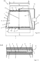
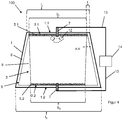
- the thermoplastic intermediate layer 4 is made of polyvinyl butyral (PVB) and has a thickness of 0.76 mm.
- PVB polyvinyl butyral
- an electrically conductive coating 6 is applied on the inside surface III of the first disc 1.
- the electrically conductive coating 6 is a layer system which contains, for example, three electrically conductive silver layers which are separated from one another by dielectric layers. If a current flows through the electrically conductive coating 6 in the electrical heating area 3, it is heated as a result of its electrical resistance and Joule heat development.
- the electrically conductive coating 6 can therefore be used for active heating of the disk 100.
- the electrically conductive coating 6 extends, for example, over the entire surface III of the first pane 1 minus a peripheral frame-shaped uncoated area, the so-called edge deletion 8, with a width r of 10 mm.
- the edge deletion 8 is used for electrical insulation between the live electrically conductive coating 6 and the vehicle body.
- the region of the edge deletion 8 is hermetically sealed by bonding to the intermediate layer 4 in order to protect the electrically conductive coating 6 from damage and corrosion.
- the bus bars 5.1, 5.2 contain, for example silver particles and were applied by screen printing and then baked.
- the bus bars 5.1, 5.2 have a constant thickness of, for example, about 10 ⁇ m and a constant resistivity of, for example, 2.3 ⁇ Ohm.cm.
- the electric heating area 3 is electrically divided by a separating line 9 with a trapezoidal outline of the electrically conductive coating 6. This means that the dividing line 9 galvanically isolates the electrically conductive coating 6 in the electrical heating region 3 from the electrically conductive coating 6.
- the arranged on the first base side 3.1 of the electrical heating region 3 busbars 5.1 for example, has the length b 1 of the first base side 3.1 of the electric heating portion 3 and disposed on the lower second base side 3.2 of the electrical heating region 3 busbars 5.2 has this example, the length b 2 the second base 3.2 of the electric heating 3.
- the length l 1 of the first base side 1.1 of the first pane 1 is for example 900 mm and the length l 2 of the second base side 1.2 is for example 1000 mm.
- FIG. 1B schematically shows a cross section through the disc 100 according to the invention along the section line A-A '.
- the dividing line 9 has a width d of, for example, 100 ⁇ m and is introduced, for example, by laser structuring into the electrically conductive coating 6. Dividing lines 9 with such a small width are visually barely perceptible and interfere with the viewing through the disc 100 only slightly, which is particularly for use in vehicles of particular importance for driving safety.
- an opaque ink layer known per se as a masking pressure can be prevented that the area of the bus bars 5.1, 5.2 is visible to a viewer.
- the cover printing not shown here can be applied, for example, on the inside surface II of the second disc 2 frame-shaped.
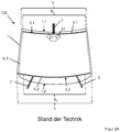
- an electrically conductive coating 6 is applied, which in the structure of the electrically conductive coating 6 from Figure 1A equivalent.
- Figure 1A has the in FIG. 2A arranged on the lower edge of the disc 100 second bus bar 5.2 two leads 7 instead of only one supply line.
- the length l 1 of the first base side 1.1 of the first disk 1 is 1220 mm, for example, and the length l 2 of the second base side 1.2 is 1440 mm, for example.
- the electric heating area 3 corresponds to the entire area of the electrically conductive coating 6 because there is no division by a dividing line.
- the disc has a first bus bar 5.1 at the upper edge.
- the current is fed through a supply line 7, in this first bus bar 5.1.
- the current flows through the electric heating area 3 into a second bus bar 5.2, which is arranged in the lower area of the pane 100.
- the second bus bar 5.2 is connected at its right and left ends, each with a feed line 7.
- the bus bars 5.1, 5.2 have, for example, a width of 16 mm and a thickness of 10 microns.
- the electrically conductive coating 6 has, for example, a sheet resistance of 0.9 ohms / square. For a finite element simulation, a voltage of 14 V between the lower supply lines 7 and the upper supply line 7 and an ambient temperature of 22 ° C was assumed. Furthermore, in the simulation, a heating time of 12 min. accepted.
- FIG. 2B shows the simulation of the temperature distribution of the comparative example according to the prior art according to FIG. 2A ,
- the positions of the leads 7 are indicated by arrows.
- the temperature distribution is uneven, especially in the critical central field of view 10.
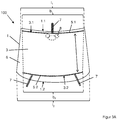
- FIG. 3A shows a plan view of a further embodiment of a disc 100 according to the invention.
- the first disc 1, the second disc 2, the electrically conductive coating 6, the thermoplastic intermediate layer 4 and the outer leads 7 are as in FIG. 2A designed.
- an electrical heating region 3 is separated from the electrically conductive coating 6 by a dividing line 9.
- This dividing line 9 limits the flow of current from the first bus bar 5.1 to the opposite second bus bar 5.2.
- the dividing lines 9 were introduced into the electrical heating layer 3 by laser structuring.
- the width of the individual dividing lines 9 is for example 100 microns, whereby the transparency through the disc 100 and its visual appearance is only minimally affected.
- the length l 1 of the first base side 1.1 of the first pane 1 is for example 1220 mm and the length l 2 of the second base side 1.2 is 1440 mm, for example, according to the comparative example FIG. 2A ,
- FIG. 3B shows the simulation of the temperature distribution of the disc 100 according to the invention FIG. 3A , After 12 min.
- T5 32.5 ° C to 35.0 ° C.
- the entire central field of view 10 would be completely freed from icing or fogging within a short time and an unobstructed view was established.
- FIG. 3A shows significantly improved heating properties than prior art disc 100 of the comparative example FIG. 2A , With almost the same averaged specific heating power in the electric heating area 3 from 351.5 W / m 2 of the comparative example to 350.9 W / m 2 of the pane 100 according to the invention FIG. 3A , has the inventive disc 100 after FIG. 3A a more uniform and higher heating of the important central field of view 10 than the comparative example.
- FIG. 3A has 10 improved heating properties in the critical central field of view.
- simulations after the same time as in the comparative example of 12 min. Resulted in uniform heating to an average temperature T5 of 32.5 ° C to 35.0 ° C over the entire central viewing area 10. Due to the small width of the dividing lines 9, the view is through the disc 100 according to the invention only minimally impaired and meets the requirements for a vehicle glazing.
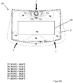
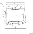
- FIG. 4 shows a plan view of a further embodiment of a disc 100 according to the invention.
- the first disc 1 with the electrically conductive coating 6 corresponds in its construction and its dimensions of the disc 100 from Figure 1A , wherein only the electric heating area 3 is formed differently by another guide of the dividing line 9.
- the electrically conductive coating 6 in the electric heating region 3 has three coating-free regions 12, which are arranged in the upper region of the first wafer 1 and approximately in the center of the bases 1.1, 1.2.
- the distance h 1 of the bus bars 5.1, 5.2 in the middle of the electric heating area 3 is greater than the distance h 2 of the bus bars 5.1, 5.2 at the outer edges of the electric heating area 3.
- the distance h 1 is for example 900 mm and the distance h 2 is 800 mm.
- the length l 1 of the first base side 1.1 of the first pane 1 is for example 1220 mm and the length l 2 of the second base side 1.2 is 1440 mm, for example, as in the comparative example FIG. 3A ,
- Such a ratio of the lengths b 1 : b 2 within the preferred range according to the invention of 1.01 to v: 0.50 is particularly advantageous for electrical heating regions 3, the distance h 1 of the bus bars 5.1, 5.2 in the middle of the electric heating. 3 greater than the distance h 2 of the bus bars 5.1, 5.2 at the outer edges of the electric heating zone 3.
- the result is a much more homogeneous heating power distribution and a more uniform temperature distribution when applying a voltage than in prior art wafers, in which b 1 : b 2 is outside the scope of the invention.
- FIG. 6 shows a flowchart of an embodiment of the inventive method for producing an electrically heated disc 100th
- discs 100 according to the invention with parting lines 9 show markedly improved heating properties, improved homogeneity of the heating power distribution and a more uniform temperature distribution at higher temperatures in particularly important disc areas.
- the view through the pane 100 is only minimally impaired by the dividing lines 9 according to the invention.
Landscapes
- Engineering & Computer Science (AREA)
- Physics & Mathematics (AREA)
- Optics & Photonics (AREA)
- Plasma & Fusion (AREA)
- Mechanical Engineering (AREA)
- Surface Heating Bodies (AREA)
- Joining Of Glass To Other Materials (AREA)
- Resistance Heating (AREA)
- Surface Treatment Of Glass (AREA)
- Central Heating Systems (AREA)
Description
Die Erfindung betrifft eine Scheibe mit elektrischem Heizbereich, ein Verfahren zu deren Herstellung und deren Verwendung.The invention relates to a disc with electric heating, a process for their preparation and their use.
Das Sichtfeld einer Fahrzeugscheibe, insbesondere einer Windschutzscheibe muss frei von Eis und Beschlag gehalten werden. Bei Kraftfahrzeugen mit Verbrennungsmotor kann beispielsweise ein mittels Motorwärme erwärmter Luftstrom auf die Scheiben gelenkt werden.The field of vision of a vehicle window, in particular a windshield, must be kept free of ice and fogging. In motor vehicles with internal combustion engine, for example, a heated by means of engine heat air flow can be directed to the discs.
Alternativ kann die Scheibe eine elektrische Heizfunktion aufweisen.
Des Weiteren sind Verbundscheiben bekannt, die auf einer innenseitigen Oberfläche einer der Einzelscheiben eine transparente, elektrisch leitfähige Beschichtung aufweisen. Durch eine externe Spannungsquelle kann ein elektrischer Strom durch die elektrisch leitfähige Beschichtung geleitet werden, der die Beschichtung und damit die Scheibe erwärmt.
Weiterer Stand der Technik kann
Die elektrische Kontaktierung der elektrisch leitfähigen Beschichtung erfolgt typischerweise über Sammelleiter, wie aus
Die Aufgabe der vorliegenden Erfindung besteht darin, eine verbesserte Scheibe mit elektrischem Heizbereich mit gleichmäßigerer Heizleistungsverteilung bereitzustellen, die einfach und kostengünstig herzustellen ist.The object of the present invention is to provide an improved electric heating panel with a more uniform heating power distribution, which is simple and inexpensive to manufacture.
Die Aufgabe der vorliegenden Erfindung wird erfindungsgemäß durch eine Scheibe mit elektrischem Heizbereich gemäß Anspruch 1 gelöst. Bevorzugte Ausführungen gehen aus den Unteransprüchen hervor.The object of the present invention is achieved by a disc with electric heating range according to
Die erfindungsgemäße Scheibe mit elektrischem Heizbereich umfasst zumindest die folgenden Merkmale:
- eine im Wesentlichen trapezförmige erste Scheibe mit einer Oberfläche III, einer ersten Grundseite mit Länge l1 und einer zweiten Grundseite mit Länge l2, wobei das Verhältnis v der Längen der Grundseiten
v = l1 : l2 von 0,70 : 1 bis 0,98 : 1
beträgt, - mindestens eine elektrisch leitfähige Beschichtung, die zumindest auf einem Teil der Oberfläche III aufgebracht ist,
- mindestens einen im Wesentlichen trapezförmigen elektrischen Heizbereich, der durch mindestens eine Trennlinie von der elektrisch leitfähigen Beschichtung elektrisch unterteilt ist und eine erste Grundseite des elektrischen Heizbereichs unmittelbar benachbart zur ersten Grundseite der ersten Scheibe und eine zweite Grundseite des elektrischen Heizbereichs unmittelbar benachbart zu der zweiten Grundseite der ersten Scheibe angeordnet ist,
- mindestens zwei zum Anschluss an eine Spannungsquelle vorgesehene Sammelleiter, die mit der elektrisch leitfähigen Beschichtung im elektrischen Heizbereich so verbunden sind, dass zwischen den Sammelleitern ein Strompfad für einen Heizstrom geformt ist,
b1 : b2 von v : 0,99 bis v : 0,50
beträgt.The pane with electric heating area according to the invention comprises at least the following features:
- a substantially trapezoidal first disc having a surface III, a first base side of length l 1 and a second base side of length l 2 , wherein the ratio v of the lengths of the bases
v = 1 1 : 1 2 from 0.70: 1 to 0.98: 1
is, - at least one electrically conductive coating, which is applied at least on a part of the surface III,
- at least one substantially trapezoidal electric heating portion electrically divided by at least one parting line of the electrically conductive coating, and a first base side of the electric heating portion immediately adjacent to the first base side of the first disc and a second base side of the electric heating portion immediately adjacent to the second base side first disc is arranged
- at least two bus bars provided for connection to a voltage source, which are connected to the electrically conductive coating in the electrical heating area in such a way that a current path for a heating current is formed between the bus bars,
b 1 : b 2 from v: 0.99 to v: 0.50
is.
Unter einer im Wesentlichen trapezförmigen Scheibe wird hier eine Scheibe mit in etwa trapezförmigem Umriss beschrieben. Wie üblich, werden im Folgenden die beiden parallelen oder im Wesentlichen parallelen Seiten des Trapezes Grundseiten genannt und die beiden angrenzenden (im Allgemeinen nicht parallelen) Seiten als Schenkel bezeichnet.Below a substantially trapezoidal disk, a disk with an approximately trapezoidal outline is described here. As usual, hereinafter the two parallel or substantially parallel sides of the trapezium are called base sides and the two adjacent (generally non-parallel) sides are called legs.
Der im Wesentlichen trapezförmige Umriss der Scheibe kann eine oder mehreren gekrümmte oder abgeknickte Seitenkanten aufweisen. So sind bei vielen derartigen Scheiben jedenfalls die Grundseiten des Trapezes, gekrümmt. Die Schenkel sind hingegen oftmals im Wesentlichen geradlinig. Des Weiteren können die Ecken der Scheibe abgerundet sein. Entsprechendes gilt für den im Wesentlichen trapezförmigen Heizbereich. Die Sammelleiter können geradlinig verlaufen oder bevorzugt entlang der Grundseiten der Scheibe verlaufen und deren Krümmung nachbilden. Zwischen Sammelleiter und Grundseite der Scheibe kann auch ein Abstand vorliegen, indem beispielsweise ein weiterer elektrischer Heizbereich wie eine Wischerfeldheizung angeordnet sein können.The substantially trapezoidal outline of the disc may have one or more curved or kinked side edges. So are many such At least the basal sides of the trapezium, curved. The legs, however, are often essentially straight. Furthermore, the corners of the disc can be rounded. The same applies to the substantially trapezoidal heating area. The bus bars can run in a straight line or preferably run along the base sides of the disc and emulate their curvature. There may also be a spacing between the bus bar and the base side of the pane, for example by arranging another electric heating area, such as a wiper field heater.
Bei Scheiben nach dem Stand der Technik ohne Trennlinien entspricht der elektrische Heizbereich dem Bereich der elektrisch leitfähigen Beschichtung. Derartige Scheiben haben in der Regel eine sehr inhomogene Heizleistungsverteilung. Sie weisen bei Beheizung besonders im Bereich der längeren Grundseite eine niedrigere Heizleistung und damit eine niedrigere Temperatur sowie ein schlechteres Abtau- und Antibeschlagverhalten auf.In prior art wafers without dividing lines, the electrical heating area corresponds to the area of the electrically conductive coating. Such disks usually have a very inhomogeneous heating power distribution. When heated, especially in the area of the longer base side, they have a lower heating power and thus a lower temperature as well as a worse defrosting and defogging behavior.
Die Erfindung beruht auf der Erkenntnis, dass durch Trennlinien ein erfindungsgemäßer elektrischer Heizbereich ausgebildet wird und dadurch eine Optimierung des Strompfades erzielt werden kann. Dies führt zu einer homogeneren Heizleistungsverteilung und Temperaturverteilung. Gleichzeitig bleibt der Strukturierungsaufwand zur Einbringung der Trennlinien zeitlich und finanziell wirtschaftlich akzeptabel.The invention is based on the recognition that an electrical heating area according to the invention is formed by parting lines and thereby an optimization of the current path can be achieved. This leads to a more homogeneous heating power distribution and temperature distribution. At the same time, the structuring effort to introduce the dividing lines remains economically and financially acceptable.
Die Trennlinien müssen besonders dünn ausgebildet sein, um die Durchsicht der Scheibe möglichst wenig zu beeinträchtigen. In einer vorteilhaften Ausgestaltung der erfindungsgemäßen Scheibe beträgt die Breite d der Trennlinien von 30 µm bis 200 µm und bevorzugt von 70 µm bis 140 µm. Dies hat den besonderen Vorteil, dass Trennlinien mit einer derart geringen Breite die Durchsicht durch die Scheibe nicht oder nur sehr geringfügig beeinträchtigen.The dividing lines must be made particularly thin in order to minimize the visibility of the pane. In an advantageous embodiment of the pane according to the invention, the width d of the separating lines is from 30 .mu.m to 200 .mu.m and preferably from 70 .mu.m to 140 .mu.m. This has the particular advantage that dividing lines with such a narrow width do not or only very slightly affect the view through the pane.
Erfindungsgemäße Scheiben weisen eine erste Grundseite mit Länge l1 und eine zweite Grundseite mit Länge l2 auf, wobei das Verhältnis v der Längen der Grundseiten v = l1 : l2 von 0,70 : 1 bis 0,98 : 1 beträgt.Discs according to the invention have a first base side with length l 1 and a second base side with length l 2 , wherein the ratio v of the lengths of the base sides v = l 1 : l 2 is from 0.70: 1 to 0.98: 1.
Die Länge der jeweiligen Grundseite der ersten Scheibe berechnet sich dabei entlang des Wegs der Seitenkante und damit entlang einer etwaigen Krümmung der Scheibe. Die mindestens eine elektrisch leitfähige Beschichtung ist zumindest auf einem Teil der Oberfläche III aufgebracht und insbesondere auf der gesamten Oberfläche III der Scheibe, abzüglich einer Randentschichtung und eventuell abzüglich von entschichteten Bereichen, die beispielsweise als Kommunikationsfenster dienen.The length of the respective base side of the first disc is calculated along the path of the side edge and thus along a possible curvature of the disc. The at least one electrically conductive coating is applied at least on a part of the surface III and in particular on the entire surface III of the pane, minus a delimitation and possibly less stripped areas, which serve as communication windows, for example.
Der im Wesentlichen trapezförmige elektrische Heizbereich wird durch mindestens eine Trennlinie von der elektrisch leitfähigen Beschichtung elektrisch unterteilt. Im Falle einer Unterteilung durch genau eine Trennlinie beschreibt die Trennlinie bevorzugt den Umriss eines Trapezes. Die Sammelleiter sind dann vollständig oder teilweise innerhalb der von der Trennlinie umschlossenen Fläche angeordnet. Im Falle einer Unterteilung durch zwei oder mehr Trennlinien verlaufen die Trennlinien bevorzugt zwischen den Grundseiten des elektrischen Heizbereichs und zwischen den Sammelleitern.The substantially trapezoidal electric heating region is electrically divided by at least one parting line of the electrically conductive coating. In the case of a subdivision by exactly one dividing line, the dividing line preferably describes the outline of a trapezoid. The bus bars are then arranged wholly or partially within the area enclosed by the dividing line. In the case of a subdivision by two or more dividing lines, the dividing lines preferably run between the bases of the electric heating area and between the bus bars.
Eine erste Grundseite des elektrischen Heizbereichs ist unmittelbar benachbart zur ersten Grundseite der ersten Scheibe und eine zweite Grundseite des elektrischen Heizbereichs unmittelbar benachbart zu der zweiten Grundseite der ersten Scheibe angeordnet. Unmittelbar benachbart bedeutet hier, dass die zweite Grundseite des elektrischen Heizbereichs zwischen der ersten Grundseite des elektrischen Heizbereichs und der zweiten Grundseite der ersten Scheibe angeordnet ist und nicht zwischen der ersten Grundseite des elektrischen Heizbereichs und der ersten Grundseite der Scheibe angeordnet ist.A first base side of the electric heating portion is disposed immediately adjacent to the first base side of the first disk and a second base side of the electric heating portion is disposed immediately adjacent to the second base side of the first disk. Immediately adjacent here means that the second base side of the electric heating portion is disposed between the first base side of the electric heating portion and the second base side of the first disc and is not disposed between the first base side of the electric heating portion and the first base side of the disc.
In einer vorteilhaften Ausgestaltung einer erfindungsgemäßen Scheibe ist die erste Grundseite des Heizbereichs im Wesentlichen parallel zur ersten Grundseite der ersten Scheibe angeordnet.In an advantageous embodiment of a pane according to the invention, the first base side of the heating area is arranged substantially parallel to the first base side of the first pane.
In einer weiteren vorteilhaften Ausgestaltung einer erfindungsgemäßen Scheibe entspricht die Länge der kürzeren der beiden Grundseiten der ersten Scheibe der Länge der unmittelbar benachbarten Grundseite des Heizbereichs zuzüglich der Breite r einer Randentschichtung, das bedeutet: l1/2 ist ungefähr gleich b1/2 + 2 r. Dies hat den besonderen Vorteil, dass die Scheibe möglichst großflächig elektrisch beheizt werden kann.In a further advantageous embodiment of a pane according to the invention, the length of the shorter of the two base sides of the first pane corresponds to the length of the immediately adjacent base side of the heating area plus the width r of an edge deletion, which means: l 1/2 is approximately equal to b 1/2 + 2 r. This has the particular advantage that the disk can be electrically heated as large as possible.
Mindestens zwei und insbesondere genau zwei zum Anschluss an eine Spannungsquelle vorgesehene Sammelleiter sind so mit der elektrisch leitfähigen Beschichtung im elektrischen Heizbereich verbunden, dass bei Anliegen einer Spannung zwischen den Sammelleitern ein Strompfad für einen Heizstrom geformt ist und den Heizbereich samt zugehörigen Teil der Scheibe erwärmt.At least two and in particular exactly two bus bars provided for connection to a voltage source are connected to the electrically conductive coating in the electrical heating area such that, when a voltage is applied between the bus bars, a current path is formed for a heating current and heats the heating area together with the associated part of the pane.
Die Sammelleiter weisen mindestens die Länge der Grundseite des Heizbereichs auf, an der sie angeordnet sind. Bei gegebenen Verhältnis v der Längen der Grundseiten der ersten Scheibe beträgt das erfindungsgemäße Verhältnis der Länge b1 der ersten Grundseite des Heizbereichs zur Länge b2 der zweiten Grundseite des Heizbereichs
b1 : b2 von v : 0,99 bis v : 0,50.The bus bars have at least the length of the base side of the heating area on which they are arranged. Given the ratio v of the lengths of the base sides of the first disk, the ratio according to the invention of the length b 1 of the first base side of the heating area to the length b 2 of the second base side of the heating area
b 1 : b 2 from v: 0.99 to v: 0.50.
Die Länge der jeweiligen Grundseite des Heizbereichs berechnet sich dabei entlang der Erstreckungsrichtung (also der längeren Ausdehnung) des jeweiligen Sammelleiters und damit entlang einer etwaigen Krümmung der Grundseite.The length of the respective base side of the heating area is calculated along the extension direction (ie the longer extent) of the respective busbar and thus along any curvature of the base side.
In einer vorteilhaften Ausgestaltung einer erfindungsgemäßen Scheibe weist die erste Scheibe und/oder der elektrische Heizbereich die Form eines symmetrischen Trapezes auf. Dadurch lässt sich eine besonders vorteilhafte und homogene Heizleistungsverteilung erzielen.In an advantageous embodiment of a pane according to the invention, the first pane and / or the electric heating area has the shape of a symmetrical trapezoid. This makes it possible to achieve a particularly advantageous and homogeneous heating power distribution.
In einer vorteilhaften Ausgestaltung einer erfindungsgemäßen Scheibe ist das Verhältnis der Länge b1 der ersten Grundseite des Heizbereichs zur Länge b2 der zweiten Grundseite des Heizbereichs ungleich 1, das heißt der elektrische Heizbereich ist nicht rechteckig. Rechteckige Heizbereiche zeigen zwar homogene Heizleistungsverteilungen, aber sind optisch auffälliger als trapezförmige Heizbereiche, die sich einfacher in der dreidimensionalen Krümmung der Scheibe optisch integrieren lassen.In an advantageous embodiment of a pane according to the invention, the ratio of the length b 1 of the first base side of the heating area to the length b 2 of the second base side of the heating area is not equal to 1, that is, the electric heating area is not rectangular. Although rectangular heating areas show homogeneous distribution of heating power, they are visually more conspicuous than trapezoidal heating areas, which are easier to optically integrate into the three-dimensional curvature of the pane.
In einer weiteren vorteilhaften Ausgestaltung einer erfindungsgemäßen Scheibe beträgt das Verhältnis der Länge b1 der ersten Grundseite des Heizbereichs zur Länge b2 der zweiten Grundseite des Heizbereichs
b1 : b2 von v : 0,99 bis 0,99.In a further advantageous embodiment of a pane according to the invention, the ratio of the length b 1 of the first base side of the heating area to the length b 2 of the second base side of the heating area
b 1 : b 2 from v: 0.99 to 0.99.
Dies ist besonders vorteilhaft um, die Seitenbereiche der Scheibe im Bereich der längeren der beiden Grundseiten möglichst weitreichend zu beheizen und dennoch eine erfindungsgemäße homogenere Heizleistungsverteilung zu erzielen.This is particularly advantageous in order to heat the side areas of the pane as far as possible in the area of the longer of the two base sides and nevertheless to achieve a homogeneous heating power distribution according to the invention.
In einer weiteren vorteilhaften Ausgestaltung einer erfindungsgemäßen Scheibe beträgt das Verhältnis der Länge b1 der ersten Grundseite des Heizbereichs zur Länge b2 der zweiten Grundseite des Heizbereichs
b1 : b2 von 1,01 bis v : 0,50.In a further advantageous embodiment of a pane according to the invention, the ratio of the length b 1 of the first base side of the heating area to the length b 2 of the second base side of the heating area
b 1 : b 2 from 1.01 to v: 0.50.
Dies ist besonders vorteilhaft, um eine Verbesserung der Homogenität der Heizleistungsverteilung zu erreichen, wenn innerhalb des elektrischen Heizbereichs mindestens ein entschichteter oder beschichtungsfreier Bereich, beispielsweise zur Ausbildung eines Kommunikationsfensters angeordnet ist, wobei der entschichtete oder beschichtungsfreie Bereiche bevorzugt in der Scheibenmitte angeordnet ist.This is particularly advantageous in order to achieve an improvement in the homogeneity of the heating power distribution if at least one stripped or coating-free region, for example for forming a communication window, is arranged within the electrical heating region, wherein the stripped or coating-free regions are preferably arranged in the middle of the pane.
Dies ist weiterhin besonders vorteilhaft, wenn der Abstand h1 der Sammelleiter in der Mitte des elektrischen Heizbereichs größer ist als der Abstand h2 der Sammelleiter an den äußeren Rändern des elektrischen Heizbereichs. Es versteht sich, dass die entschichteten oder beschichtungsfreien Bereiche auch mit einem größeren Abstand h1 im Vergleich mit h2 kombiniert sein können.This is furthermore particularly advantageous if the distance h 1 of the bus bars in the middle of the electric heating area is greater than the distance h 2 of the bus bars at the outer edges of the electric heating area. It is understood that the stratified or coating-free areas can also be combined with a larger distance h 1 in comparison with h 2 .
Die Breite des ersten und zweiten Sammelleiters beträgt bevorzugt von 2 mm bis 30 mm, besonders bevorzugt von 4 mm bis 20 mm und insbesondere von 10 mm bis 20 mm. Dünnere Sammelleiter führen zu einem zu hohen elektrischen Widerstand und damit zu einer zu hohen Erwärmung des Sammelleiters im Betrieb. Des Weiteren sind dünnere Sammelleiter nur schwer durch Drucktechniken wie Siebdruck herzustellen. Dickere Sammelleiter erfordern einen unerwünscht hohen Materialeinsatz. Des Weiteren führen sie zu einer zu großen und unästhetischen Einschränkung des Durchsichtbereichs der Scheibe. Die Länge des Sammelleiters richtet sich nach der Ausdehnung des elektrischen Heizbereichs. Bei einem Sammelleiter, der typischerweise in Form eines Streifens ausgebildet ist, wird die längere seiner Dimensionen als Länge und die weniger lange seiner Dimensionen als Breite bezeichnet. Sollten weitere Sammelleiter vorhanden sein, können diese auch dünner ausgestaltet sein, bevorzugt von 0,6 mm bis 5 mm.The width of the first and second bus bars is preferably from 2 mm to 30 mm, more preferably from 4 mm to 20 mm and in particular from 10 mm to 20 mm. Thinner busbars lead to excessive electrical resistance and thus to excessive heating of the busbar during operation. Furthermore, thinner bus bars are difficult to produce by printing techniques such as screen printing. Thicker busbars require an undesirably high material usage. Furthermore, they lead to a large and unaesthetic restriction of the viewing area of the disc. The length of the busbar depends on the extent of the electrical heating area. In a bus bar, which is typically in the form of a strip, the longer of its dimensions is referred to as the length and the less long of its dimensions as the width. If further bus bars are present, they can also be made thinner, preferably from 0.6 mm to 5 mm.
In einer vorteilhaften Ausgestaltung ist der erfindungsgemäße Sammelleiter als aufgedruckte und eingebrannte leitfähige Struktur ausgebildet. Der aufgedruckte Sammelleiter enthält bevorzugt zumindest ein Metall, eine Metalllegierung, eine Metallverbindung und/oder Kohlenstoff, besonders bevorzugt ein Edelmetall und insbesondere Silber. Die Druckpaste enthält bevorzugt metallische Partikel Metallpartikel und/oder Kohlenstoff und insbesondere Edelmetallpartikel wie Silberpartikel. Die elektrische Leitfähigkeit wird bevorzugt durch die elektrisch leitenden Partikel erzielt. Die Partikel können sich in einer organischen und / oder anorganischen Matrix wie Pasten oder Tinten befinden, bevorzugt als Druckpaste mit Glasfritten.In an advantageous embodiment, the bus bar according to the invention is designed as a printed and baked conductive structure. The printed bus bar preferably contains at least one metal, one metal alloy, one metal compound and / or carbon, particularly preferably one noble metal and in particular silver. The printing paste preferably contains metallic particles metal particles and / or carbon and in particular noble metal particles such as silver particles. The electrical conductivity is preferably achieved by the electrically conductive particles. The particles may be in an organic and / or inorganic matrix such as pastes or inks, preferably as a printing paste with glass frits.
Die Schichtdicke des aufgedruckten Sammelleiters beträgt bevorzugt von 5 µm bis 40 µm, besonders bevorzugt von 8 µm bis 20 µm und ganz besonders bevorzugt von 8 µm bis 12 µm. Aufgedruckte Sammelleiter mit diesen Dicken sind technisch einfach zu realisieren und weisen eine vorteilhafte Stromtragfähigkeit auf.The layer thickness of the printed bus bar is preferably from 5 μm to 40 μm, particularly preferably from 8 μm to 20 μm and very particularly preferably from 8 μm to 12 μm. Printed busbars with these thicknesses are technically easy to implement and have an advantageous current carrying capacity.
Der spezifische Widerstand ρa der Sammelleiter beträgt bevorzugt von 0.8 µOhm•cm bis 7.0 µOhm•cm und besonders bevorzugt von 1.0 µOhm•cm bis 2.5 µOhm•cm. Sammelleiter mit spezifischen Widerständen in diesem Bereich sind technisch einfach zu realisieren und weisen eine vorteilhafte Stromtragfähigkeit auf.The specific resistance ρ a of the bus bars is preferably from 0.8 μOhm • cm to 7.0 μOhm • cm and particularly preferably from 1.0 μOhm • cm to 2.5 μOhm • cm. Busbars with specific resistances in this area are technically easy to implement and have an advantageous current carrying capacity.
Alternativ kann der Sammelleiter aber auch als Streifen einer elektrisch leitfähigen Folie ausgebildet sein. Der Sammelleiter enthält dann beispielsweise zumindest Aluminium, Kupfer, verzinntes Kupfer, Gold, Silber, Zink, Wolfram und/oder Zinn oder Legierungen davon. Der Streifen hat bevorzugt eine Dicke von 10 µm bis 500 µm, besonders bevorzugt von 30 µm bis 300 µm. Sammelleiter aus elektrisch leitfähigen Folien mit diesen Dicken sind technisch einfach zu realisieren und weisen eine vorteilhafte Stromtragfähigkeit auf. Der Streifen kann mit der elektrisch leitfähigen Struktur beispielsweise über eine Lotmasse, über einen elektrisch leitfähigen Kleber oder durch direktes Auflegen elektrisch leitend verbunden sein.Alternatively, the bus bar can also be designed as a strip of an electrically conductive foil. The bus bar then contains, for example, at least aluminum, copper, tin-plated copper, gold, silver, zinc, tungsten and / or tin or alloys thereof. The strip preferably has a thickness of 10 μm to 500 μm, more preferably of 30 μm to 300 μm. Busbars made of electrically conductive films with these thicknesses are technically easy to implement and have an advantageous current carrying capacity. The strip may be electrically conductively connected to the electrically conductive structure, for example via a solder mass, via an electrically conductive adhesive or by direct placement.
Die erfindungsgemäße Scheibe umfasst eine erste Scheibe, auf der eine elektrische leitfähige Beschichtung angeordnet ist. Je nach Material der elektrisch leitfähigen Beschichtung kann es vorteilhaft sein, die Beschichtung mit einer Schutzschicht, beispielsweise einem Lack, einer Polymerfolie und/oder einer zweiten Scheibe zu schützen.The pane according to the invention comprises a first pane on which an electrically conductive coating is arranged. Depending on the material of the electrically conductive coating, it may be advantageous to protect the coating with a protective layer, for example a lacquer, a polymer film and / or a second pane.
In einer vorteilhaften Ausgestaltung der erfindungsgemäßen Scheibe ist die Oberfläche der ersten Scheibe, auf der die elektrische leitfähige Beschichtung angeordnet ist, über eine thermoplastische Zwischenschicht mit einer zweiten Scheibe flächig verbunden ist. Alternativ kann die elektrisch leitfähige Beschichtung auf der ersten Scheibe angeordnet werden, indem sie auf eine Trägerfolie, beispielsweise eine Polyethylenterephthalat(PET)-Folie aufgebracht wird und diese über eine Zwischenschicht, beispielsweise eine Polyvinylbutyral-(PVB)-Folie, mit der ersten Scheibe verbunden ist.In an advantageous embodiment of the pane according to the invention, the surface of the first pane, on which the electrically conductive coating is arranged, is connected in a planar manner via a thermoplastic intermediate layer to a second pane. Alternatively, the electrically conductive coating may be disposed on the first pane by being applied to a carrier film, such as a polyethylene terephthalate (PET) film, and bonded to the first pane via an intermediate layer, such as a polyvinyl butyral (PVB) film is.
Als erste und gegebenenfalls zweite Scheibe sind im Grunde alle elektrisch isolierenden Substrate geeignet, die unter den Bedingungen der Herstellung und der Verwendung der erfindungsgemäßen Scheibe thermisch und chemisch stabil sowie dimensionsstabil sind.Basically, all electrically insulating substrates which are thermally and chemically stable and dimensionally stable under the conditions of production and use of the pane according to the invention are suitable as the first and optionally second pane.
Die erste Scheibe und/oder die zweite Scheibe enthalten bevorzugt Glas, besonders bevorzugt Flachglas, Floatglas, Quarzglas, Borosilikatglas, Kalk-Natron-Glas, oder klare Kunststoffe, vorzugsweise starre klare Kunststoffe, insbesondere Polyethylen, Polypropylen, Polycarbonat, Polymethylmethacrylat, Polystyrol, Polyamid, Polyester, Polyvinylchlorid und/oder Gemische davon. Die erste Scheibe und/oder die zweite Scheibe sind bevorzugt transparent, insbesondere für die Verwendung der Scheibe als Windschutzscheide oder Rückscheibe eines Fahrzeugs oder anderen Verwendungen bei denen eine hohe Lichttransmission erwünscht ist. Als transparent im Sinne der Erfindung wird dann eine Scheibe verstanden, die eine Transmission im sichtbaren Spektralbereich von größer 70 % aufweist. Für Scheiben, die nicht im verkehrsrelevanten Sichtfeld des Fahrers liegen, beispielsweise für Dachscheiben, kann die Transmission aber auch viel geringer sein, beispielsweise größer als 5 %.The first pane and / or the second pane preferably contains glass, particularly preferably flat glass, float glass, quartz glass, borosilicate glass, soda-lime glass, or clear plastics, preferably rigid clear plastics, in particular polyethylene, polypropylene, polycarbonate, polymethyl methacrylate, polystyrene, polyamide , Polyester, polyvinyl chloride and / or mixtures thereof. The first disc and / or the second disc are preferably transparent, in particular for the use of the disc as a windshield or rear window of a vehicle or other uses in which a high light transmission is desired. As transparent in the context of the invention is then understood a disc having a transmission in the visible spectral range of greater than 70%. For discs that are not in the traffic-related field of view of the driver, for example, for roof windows, but the transmission can also be much less, for example, greater than 5%.
Die Dicke der Scheibe kann breit variieren und so hervorragend den Erfordernissen des Einzelfalls angepasst werden. Vorzugsweise werden Scheiben mit den Standardstärken von 1,0 mm bis 25 mm, bevorzugt von 1,4 mm bis 2,5 mm für Fahrzeugglas und bevorzugt von 4 mm bis 25 mm für Möbel, Geräte und Gebäude, insbesondere für elektrische Heizkörper, verwendet. Die Größe der Scheibe kann breit variieren und richtet sich nach der Größe der erfindungsgemäßen Verwendung. Die erste Scheibe und gegebenenfalls die zweite Scheibe weisen beispielsweise im Fahrzeugbau und Architekturbereich übliche Flächen von 200 cm2 bis zu 20 m2 auf. Die Scheibe kann eine beliebige dreidimensionale Form aufweisen. Vorzugsweise hat die dreidimensionale Form keine Schattenzonen, so dass sie beispielsweise durch Kathodenzerstäubung beschichtet werden kann. Bevorzugt sind die Substrate planar oder leicht oder stark in einer Richtung oder in mehreren Richtungen des Raumes gebogen. Insbesondere werden planare Substrate verwendet. Die Scheiben können farblos oder gefärbt sein.The thickness of the disc can vary widely and so perfectly adapted to the requirements of the case. Preferably, panes of standard thicknesses from 1.0 mm to 25 mm, preferably from 1.4 mm to 2.5 mm for vehicle glass and preferably from 4 mm to 25 mm are used for furniture, appliances and buildings, in particular for electric radiators. The size of the disc can vary widely and depends on the size of the use according to the invention. The first pane and optionally the second pane have, for example, in vehicle construction and in the architectural field, conventional areas of 200 cm 2 to 20 m 2 . The disc may have any three-dimensional shape. Preferably, the three-dimensional shape has no shadow zones, so that it can be coated, for example, by sputtering. Preferably, the substrates are planar or slightly or strongly bent in one direction or in several directions of the space. In particular, planar substrates are used. The discs can be colorless or colored.
Mehrere Scheiben werden durch mindesten eine Zwischenschicht miteinander verbunden. Die Zwischenschicht enthält vorzugsweise mindestens einen thermoplastischen Kunststoff, bevorzugt Polyvinylbutyral (PVB), Ethylenvinylacetat (EVA) und / oder Polyethylenterephthalat (PET). Die thermoplastische Zwischenschicht kann aber auch beispielsweise Polyurethan (PU), Polypropylen (PP), Polyacrylat, Polyethylen (PE), Polycarbonat (PC), Polymethylmetacrylat, Polyvinylchlorid, Polyacetatharz, Gießharze, Acrylate, fluorinierte Ethylen-Propylene, Polyvinylfluorid und / oder Ethylen-Tetrafluorethylen, oder Copolymere oder Gemische davon enthalten. Die thermoplastische Zwischenschicht kann durch eine oder auch durch mehrere übereinander angeordnete thermoplastische Folien ausgebildet werden, wobei die Dicke ein thermoplastischen Folie bevorzugt von 0,25 mm bis 1 mm beträgt, typischerweise 0,38 mm oder 0,76 mm.Several disks are connected by at least one intermediate layer. The intermediate layer preferably contains at least one thermoplastic, preferably polyvinyl butyral (PVB), ethylene vinyl acetate (EVA) and / or polyethylene terephthalate (PET). However, the thermoplastic intermediate layer can also be, for example, polyurethane (PU), polypropylene (PP), polyacrylate, polyethylene (PE), polycarbonate (PC), polymethyl methacrylate, polyvinyl chloride, polyacetate resin, casting resins, acrylates, fluorinated ethylene-propylenes, polyvinyl fluoride and / or ethylene Tetrafluoroethylene, or copolymers or mixtures thereof. The thermoplastic intermediate layer can be formed by one or by a plurality of thermoplastic films arranged one above the other, wherein the thickness of a thermoplastic film is preferably from 0.25 mm to 1 mm, typically 0.38 mm or 0.76 mm.
Bei einer erfindungsgemäßen Verbundscheibe aus einer ersten Scheibe, einer Zwischenschicht und einer zweiten Scheibe kann die elektrisch leitfähige Beschichtung direkt auf der erste Scheibe aufgebracht sein oder auf eine Trägerfolie oder auf die Zwischenschicht selbst aufgebracht sein. Die erste Scheibe und die zweite Scheibe weisen jeweils eine innenseitige Oberfläche und eine außenseitige Oberfläche auf. Die innenseitigen Oberflächen der ersten und der zweiten Scheibe sind einander zugewandt und über die thermoplastische Zwischenschicht miteinander verbunden. Die außenseitigen Oberflächen der ersten und der zweiten Scheibe sind voneinander und von der thermoplastischen Zwischenschicht abgewandt. Die elektrisch leitfähige Beschichtung ist auf der innenseitigen Oberfläche der ersten Scheibe aufgebracht. Natürlich kann auch auf der innenseitigen Oberfläche der zweiten Scheibe eine weitere elektrisch leitfähige Beschichtung aufgebracht sein. Auch die außenseitigen Oberflächen der Scheiben können Beschichtungen aufweisen. Die Begriffe "erste Scheibe" und "zweiten Scheibe" sind zur Unterscheidung der beiden Scheiben bei einer erfindungsgemäßen Verbundscheibe gewählt. Mit den Begriffen ist keine Aussage über die geometrische Anordnung verbunden. Ist die erfindungsgemäße Scheibe beispielsweise dafür vorgesehen, in einer Öffnung, beispielsweise eines Fahrzeugs oder eines Gebäudes, den Innenraum gegenüber der äußeren Umgebung abzutrennen, so kann die ersten Scheibe dem Innenraum oder der äußeren Umgebung zugewandt sein.In a composite pane according to the invention comprising a first pane, an intermediate layer and a second pane, the electrically conductive coating can be applied directly to the first pane or be applied to a carrier film or to the intermediate layer itself. The first disc and the second disc each have an inside surface and an outside surface. The inside surfaces of the first and second disks face each other and are interconnected via the thermoplastic intermediate layer. The outside surfaces of the first and second disks are remote from each other and from the thermoplastic intermediate layer. The electrically conductive coating is applied to the inside surface of the first pane. Of course, a further electrically conductive coating can also be applied to the inside surface of the second pane. The outside surfaces of the discs may also have coatings. The terms "first disc" and "second disc" are chosen to distinguish the two discs in a composite disc according to the invention. With the terms no statement about the geometric arrangement is connected. Is the invention Disk provided, for example, in an opening, such as a vehicle or a building, the interior to separate from the external environment, the first pane may be facing the interior or the external environment.
Erfindungsgemäße elektrisch leitfähige Beschichtungen sind beispielsweise aus
Typischerweise ist jeweils zwischen zwei benachbarten funktionellen Schichten der elektrisch leitfähigen Beschichtung zumindest eine dielektrische Schicht angeordnet. Bevorzugt ist unterhalb der ersten und / oder oberhalb der letzten funktionellen Schicht eine weitere dielektrische Schicht angeordnet. Eine dielektrische Schicht enthält zumindest eine Einzelschicht aus einem dielektrischen Material, beispielsweise enthaltend ein Nitrid wie Siliziumnitrid oder ein Oxid wie Aluminiumoxid. Dielektrische Schicht können aber auch mehrere Einzelschichten umfassen, beispielsweise Einzelschichten eines einem dielektrischen Material, Glättungsschichten, Anpassungsschichten, Blockerschichten und / oder Antireflexionsschichten. Die Dicke einer dielektrischen Schicht beträgt beispielsweise von 10 nm bis 200 nm.Typically, at least one dielectric layer is arranged in each case between two adjacent functional layers of the electrically conductive coating. Preferably, a further dielectric layer is arranged below the first and / or above the last functional layer. A dielectric layer contains at least a single layer of a dielectric material, for example containing a nitride such as silicon nitride or an oxide such as aluminum oxide. However, dielectric layers may also comprise a plurality of individual layers, for example individual layers of a dielectric material, smoothing layers, matching layers, blocking layers and / or antireflection layers. The thickness of a dielectric layer is, for example, from 10 nm to 200 nm.
Dieser Schichtaufbau wird im Allgemeinen durch eine Folge von Abscheidevorgängen erhalten, die durch ein Vakuumverfahren wie die magnetfeldgestützte Kathodenzerstäubung durchgeführt werden.This layer construction is generally obtained by a series of depositions performed by a vacuum process such as magnetic field assisted sputtering.
Weitere geeignete elektrisch leitfähigen Beschichtungen enthalten bevorzugt Indium-Zinnoxid (ITO), fluordotiertes Zinnoxid (SnO2:F) oder aluminiumdotiertes Zinkoxid (ZnO:Al).Other suitable electrically conductive coatings preferably contain indium-tin oxide (ITO), fluorine-doped tin oxide (SnO 2 : F) or aluminum-doped zinc oxide (ZnO: Al).
Die elektrisch leitfähige Beschichtung kann prinzipiell jede Beschichtung sein, die elektrisch kontaktiert werden soll. Soll die erfindungsgemäße Scheibe die Durchsicht ermöglichen, wie es beispielsweise bei Scheiben im Fensterbereich der Fall ist, so ist die elektrisch leitfähige Beschichtung bevorzugt transparent. Die erfindungsgemäße elektrisch leitfähige Beschichtung ist bevorzugt für elektromagnetische Strahlung transparent, besonders bevorzugt für elektromagnetische Strahlung einer Wellenlänge von 300 bis 1.300 nm und insbesondere für sichtbares Licht.In principle, the electrically conductive coating can be any coating which is to be electrically contacted. If the pane according to the invention is to permit viewing, as is the case, for example, with panes in the window area, the electrically conductive coating is preferably transparent. The electrically conductive coating according to the invention is preferably transparent to electromagnetic radiation, more preferably for electromagnetic radiation of a wavelength of 300 to 1,300 nm and in particular for visible light.
In einer vorteilhaften Ausgestaltung ist die elektrisch leitfähige Beschichtung eine Schicht oder ein Schichtaufbau mehrere Einzelschichten mit einer Gesamtdicke von kleiner oder gleich 2 µm, besonders bevorzugt kleiner oder gleich 1 µm.In an advantageous embodiment, the electrically conductive coating is a layer or a layer structure of a plurality of individual layers having a total thickness of less than or equal to 2 microns, more preferably less than or equal to 1 micron.
Eine vorteilhafte erfindungsgemäße elektrisch leitfähige Beschichtung weist einen Flächenwiderstand von 0,4 Ohm/Quadrat bis 10 Ohm/Quadrat auf. In einer besonders bevorzugten Ausgestaltung weist die erfindungsgemäße elektrisch leitfähige Beschichtung einen Flächenwiderstand von 0,5 Ohm/Quadrat bis 1 Ohm/Quadrat auf. Beschichtungen mit derartigen Flächenwiderständen eignen sich besonders zur Beheizung von Fahrzeugscheiben bei typischen Bordspannungen von 12 V bis 48 Volt oder bei Elektrofahrzeugen mit typischen Bordspannungen von bis zu 500 V.An advantageous electrically conductive coating according to the invention has a sheet resistance of 0.4 ohms / square to 10 ohms / square. In a particularly preferred embodiment, the electrically conductive coating according to the invention has a sheet resistance of 0.5 ohms / square to 1 ohms / square. Coatings with surface resistances of this kind are particularly suitable for heating vehicle windows for typical on-board voltages of 12 V to 48 V or for electric vehicles with typical on-board voltages of up to 500 V.
Die elektrisch leitfähige Beschichtung kann sich über die gesamte Oberfläche der ersten Scheibe erstrecken. Die elektrische Heizschicht kann sich alternativ aber auch nur über einen Teil der Oberfläche der ersten Scheibe erstrecken. Die elektrische Heizschicht erstreckt sich bevorzugt über mindestens 50%, besonders bevorzugt über mindestens 70% und ganz besonders bevorzugt über mindestens 90% der innenseitigen Oberfläche der ersten Scheibe.The electrically conductive coating may extend over the entire surface of the first disk. Alternatively, however, the electrical heating layer may also extend only over part of the surface of the first pane. The electrical heating layer preferably extends over at least 50%, particularly preferably over at least 70% and very particularly preferably over at least 90% of the inside surface of the first pane.
Die elektrische leitfähige Beschichtung kann im elektrischen Heizbereich und/oder außerhalb des elektrischen Heizbereichs einen oder mehrere unbeschichtete, entschichtete oder beschichtungsfreie Bereiche aufweisen. Diese Bereiche können eine besonders hohe Transmission für elektromagnetische Strahlung, beispielsweise Infrarot-Strahlung, oder Radarwellen aufweisen und sind beispielsweise als Datenübertragungsfenster oder Kommunikationsfenster bekannt.The electrically conductive coating may have one or more uncoated, stripped or coating-free areas in the electrical heating area and / or outside the electric heating area. These areas can have a particularly high transmission for electromagnetic radiation, for example Infrared radiation, or radar waves and are known for example as a data transmission window or communication window.
In einer vorteilhaften Ausgestaltung einer erfindungsgemäßen Scheibe als Verbundscheibe weist die innenseitige Oberfläche der ersten Scheibe einen umlaufenden Randbereich mit einer Breite r von 2 mm bis 50 mm, bevorzugt von 5 mm bis 20 mm auf, der nicht mit der elektrisch leitfähigen Beschichtung versehen ist. Die elektrisch leitfähige Beschichtung weist dann keinen Kontakt zur Atmosphäre auf und ist im Inneren der Scheibe durch die thermoplastische Zwischenschicht vorteilhaft vor Beschädigungen und Korrosion geschützt.In an advantageous embodiment of a pane according to the invention as a composite pane, the inside surface of the first pane has a peripheral edge area with a width r of 2 mm to 50 mm, preferably 5 mm to 20 mm, which is not provided with the electrically conductive coating. The electrically conductive coating then has no contact with the atmosphere and is advantageously protected inside the pane by the thermoplastic intermediate layer from damage and corrosion.
Die Sammelleiter werden durch eine oder mehrere Zuleitungen elektrisch kontaktiert. Die Zuleitung ist bevorzugt als flexibler Folienleiter (Flachleiter, Flachbandleiter) ausgebildet. Darunter wird ein elektrischer Leiter verstanden, dessen Breite deutlich größer ist als seine Dicke. Ein solcher Folienleiter ist beispielsweise ein Streifen oder Band enthaltend oder bestehend aus Kupfer, verzinntem Kupfer, Aluminium, Silber, Gold oder Legierungen davon. Der Folienleiter weist beispielsweise eine Breite von 2 mm bis 16 mm und eine Dicke von 0,03 mm bis 0,1 mm auf. Der Folienleiter kann eine isolierende, bevorzugt polymere Ummantelung, beispielsweise auf Polyimid-Basis aufweisen. Folienleiter, die sich zur Kontaktierung von elektrisch leitfähigen Beschichtungen in Scheiben eignen, weisen lediglich eine Gesamtdicke von beispielsweise 0,3 mm auf. Derart dünne Folienleiter können ohne Schwierigkeiten zwischen den einzelnen Scheiben in der thermoplastischen Zwischenschicht eingebettet werden. In einem Folienleiterband können sich mehrere voneinander elektrisch isolierte, leitfähige Schichten befinden.The bus bars are electrically contacted by one or more leads. The supply line is preferably designed as a flexible foil conductor (flat conductor, ribbon conductor). This is understood to mean an electrical conductor whose width is significantly greater than its thickness. Such a foil conductor is, for example, a strip or band containing or consisting of copper, tinned copper, aluminum, silver, gold or alloys thereof. The film conductor has, for example, a width of 2 mm to 16 mm and a thickness of 0.03 mm to 0.1 mm. The foil conductor can have an insulating, preferably polymeric sheath, for example based on polyimide. Foil conductors which are suitable for contacting electrically conductive coatings in slices only have a total thickness of, for example, 0.3 mm. Such thin film conductors can be embedded between the individual disks in the thermoplastic intermediate layer without difficulty. A foil conductor band may contain a plurality of electrically insulated, conductive layers.
Alternativ können auch dünne Metalldrähte als elektrische Zuleitung verwendet werden. Die Metalldrähte enthalten insbesondere Kupfer, Wolfram, Gold, Silber oder Aluminium oder Legierungen mindestens zweier dieser Metalle. Die Legierungen können auch Molybdän, Rhenium, Osmium, Iridium, Palladium oder Platin enthalten.Alternatively, thin metal wires can be used as electrical supply. The metal wires contain in particular copper, tungsten, gold, silver or aluminum or alloys of at least two of these metals. The alloys may also contain molybdenum, rhenium, osmium, iridium, palladium or platinum.
In einer vorteilhaften Ausgestaltung der Erfindung wird die elektrische Zuleitung mit einem Kontaktband verbunden, beispielsweise mittels einer Lotmasse oder eines elektrisch leitfähigen Klebstoffs. Das Kontaktband ist dann mit dem Sammelleiter verbunden. Das Kontaktband ist im Sinne der Erfindung eine Verlängerung der Zuleitung, so dass die Verbindungsfläche zwischen Kontaktband und Sammelleiter die erfindungsgemäße Kontaktfläche zu verstehen ist, ab der der Abstand a in Erstreckungsrichtung des Sammelleiters verläuft.In an advantageous embodiment of the invention, the electrical supply line is connected to a contact strip, for example by means of a solder mass or an electrically conductive adhesive. The contact band is then connected to the bus bar. The contact band is in the context of the invention, an extension of the supply line, so that the connecting surface between the contact strip and bus bar the The contact surface according to the invention is to be understood, from which the distance a extends in the extension direction of the busbar.
Das Kontaktband erhöht vorteilhaft die Stromtragfähigkeit des Sammelleiters. Außerdem kann durch das Kontaktband eine unerwünschte Erhitzung der Kontaktstelle zwischen Sammelleiter und Zuleitung verringert werden. Zudem vereinfacht das Kontaktband die elektrische Kontaktierung des Sammelleiters durch die elektrische Zuleitung, weil die Zuleitung nicht mit dem bereits aufgebrachten Sammelleiter verbunden, beispielsweise verlötet werden muss.The contact band advantageously increases the current carrying capacity of the busbar. In addition, an unwanted heating of the contact point between the bus bar and supply line can be reduced by the contact band. In addition, the contact band simplifies the electrical contacting of the busbar by the electrical supply line, because the lead is not connected to the already applied bus bar, for example, must be soldered.
Das Kontaktband enthält bevorzugt zumindest ein Metall, besonders bevorzugt Kupfer, verzinntes Kupfer, Silber, Gold, Aluminium, Zink, Wolfram und / oder Zinn. Das ist besonders vorteilhaft im Hinblick auf die elektrische Leitfähigkeit des Kontaktbandes. Das Kontaktband kann auch Legierungen enthalten, welche bevorzugt eines oder mehrere der genannten Elemente und gegebenenfalls weitere Elemente enthält, beispielsweise Messing oder Bronze.The contact strip preferably contains at least one metal, more preferably copper, tin-plated copper, silver, gold, aluminum, zinc, tungsten and / or tin. This is particularly advantageous with regard to the electrical conductivity of the contact strip. The contact strip may also contain alloys which preferably contains one or more of the named elements and optionally further elements, for example brass or bronze.
Das Kontaktband ist bevorzugt als Streifen einer dünnen, elektrisch leitfähigen Folie ausgebildet. Die Dicke des Kontaktbandes beträgt bevorzugt von 10 µm bis 500 µm, besonders bevorzugt von 15 µm bis 200 µm, ganz besonders bevorzugt von 50 µm bis 100 µm. Folien mit diesen Dicken sind technisch einfach herzustellen und leicht verfügbar und weisen zudem einen vorteilhaft geringen elektrischen Widerstand auf.The contact strip is preferably formed as a strip of a thin, electrically conductive film. The thickness of the contact band is preferably from 10 .mu.m to 500 .mu.m, more preferably from 15 .mu.m to 200 .mu.m, most preferably from 50 .mu.m to 100 .mu.m. Films with these thicknesses are technically easy to produce and readily available and also have an advantageously low electrical resistance.
Die Länge des Kontaktbandes beträgt bevorzugt von 10 mm bis 400 mm, besonders bevorzugt von 10 mm bis 100 mm und insbesondere 20 mm bis 60 mm. Das ist besonders vorteilhaft im Hinblick auf eine gute Handhabbarkeit des Kontaktbandes sowie auf eine zur elektrischen Kontaktierung ausreichend große Kontaktfläche zwischen Sammelleiter und Kontaktband.The length of the contact band is preferably from 10 mm to 400 mm, more preferably from 10 mm to 100 mm and in particular 20 mm to 60 mm. This is particularly advantageous with regard to a good handling of the contact strip as well as a contact surface between the bus bar and the contact strip that is sufficiently large for making electrical contact.
Die Breite des Kontaktbandes beträgt bevorzugt von 2 mm bis 40 mm, besonders bevorzugt von 5 mm bis 30 mm. Das ist besonders vorteilhaft im Hinblick auf die Kontaktfläche zwischen Kontaktband und Sammelleiter und eine einfache Verbindung des Kontaktbandes mit der elektrischen Zuleitung. Die Ausdrücke Länge und Breite des Kontaktbandes bezeichnen jeweils die Abmessung in der gleichen Ausbreitungsrichtung, durch die die Länge beziehungsweise Breite des Sammelleiters gegeben ist.The width of the contact band is preferably from 2 mm to 40 mm, particularly preferably from 5 mm to 30 mm. This is particularly advantageous in terms of the contact area between the contact strip and bus bar and a simple connection of the contact strip with the electrical supply line. The terms length and width of the contact band each denote the dimension in the same propagation direction through which the length or width of the bus bar is given.
In einer bevorzugten Ausgestaltung steht das Kontaktband vollflächig mit der Sammelschiene in direktem Kontakt. Dazu wird ein Kontaktband auf den Sammelleiter aufgelegt. Der besondere Vorteil liegt in einer einfachen Herstellung der Scheibe und der Ausnutzung der gesamten Fläche des Kontaktbandes als Kontaktfläche.In a preferred embodiment, the contact band is in full contact with the busbar in direct contact. For this purpose, a contact strip is placed on the bus bar. The particular advantage lies in a simple manufacture of the disc and the utilization of the entire surface of the contact band as a contact surface.
Das Kontaktband kann einfach auf den Sammelleiter aufgelegt sein und wird innerhalb der laminierten Scheibe dauerhaft stabil an der vorgesehenen Position fixiert.The contact band can be easily placed on the bus bar and is fixed permanently stable in the intended position within the laminated disc.
Die Erfindung umfasst weiter ein Verfahren zur Herstellung einer Scheibe mit elektrischem Heizbereich, mindestens umfassend:
- (a) Bereitstellen einer im Wesentlichen trapezförmigen ersten Scheibe mit einer Oberfläche III, einer ersten Grundseite mit Länge l1, einer zweiten Grundseite mit Länge l2 und einem Verhältnis v der Längen der Grundseiten von
v = l1 : l2 von 0,70 : 1 bis 0,98 : 1, - (b) Aufbringen einer elektrisch leitfähigen Beschichtung auf mindestens einen Teil der Oberfläche III einer ersten Scheibe,
- (c) elektrische Unterteilen mindestens eines im Wesentlichen trapezförmigen elektrischen Heizbereichs durch mindestens eine Trennlinie von der elektrisch leitfähigen Beschichtung und Anordnen einer erste Grundseite des Heizbereichs unmittelbar benachbart zur ersten Grundseite der ersten Scheibe und einer zweite Grundseite des Heizbereichs unmittelbar benachbart zu der zweiten Grundseite der ersten Scheibe, wobei das Verhältnis der Länge b1 der ersten Grundseite des Heizbereichs zur Länge b2 der zweiten Grundseite des Heizbereichs, bei gegebenem Verhältnis v, zu
b1 : b2 von v : 0,99 bis v : 0,50
eingestellt wird, - (d) Aufbringen von mindestens zwei zum Anschluss an eine Spannungsquelle vorgesehenen Sammelleiter, die mit der elektrisch leitfähigen Beschichtung im elektrischen Heizbereich so verbunden werden, dass zwischen den Sammelleitern ein Strompfad für einen Heizstrom geformt wird.
- (A) providing a substantially trapezoidal first disc having a surface III, a first base side with length l 1 , a second base side with length l 2 and a ratio v of the lengths of the bases of
v = l 1 : l 2 from 0.70: 1 to 0.98: 1, - (b) applying an electrically conductive coating to at least part of the surface III of a first pane,
- (c) electrically dividing at least one substantially trapezoidal electric heating area by at least one parting line of the electrically conductive coating and disposing a first base side of the heating area immediately adjacent to the first base side of the first pane and a second base side of the heating area immediately adjacent to the second base side of the first Disc, wherein the ratio of the length b 1 of the first base side of the heating area to the length b 2 of the second base side of the heating area, given a ratio v, to
b 1 : b 2 from v: 0.99 to v: 0.50
is set, - (D) application of at least two provided for connection to a voltage source bus bars, which are connected to the electrically conductive coating in the electric heating region so that a current path is formed between the bus bars for a heating current.
Das Aufbringen der elektrisch leitfähigen Beschichtung in Verfahrensschritt (b) kann durch an sich bekannte Verfahren erfolgen, bevorzugt durch magnetfeldunterstützte Kathodenzerstäubung. Das ist besonders vorteilhaft im Hinblick auf eine einfache, schnelle, kostengünstige und gleichmäßige Beschichtung der ersten Scheibe. Die elektrisch leitfähige Beschichtung kann aber auch beispielsweise durch Aufdampfen, chemische Gasphasenabscheidung (chemical vapour deposition, CVD), plasmagestützte Gasphasenabscheidung (PECVD) oder durch nasschemische Verfahren aufgebracht werden.The application of the electrically conductive coating in process step (b) can be carried out by methods known per se, preferably by magnetic field-assisted sputtering. This is particularly advantageous in terms of a simple, fast, inexpensive and uniform coating of the first disc. The However, electrically conductive coating can also be applied, for example, by vapor deposition, chemical vapor deposition (CVD), plasma-assisted vapor deposition (PECVD) or by wet-chemical methods.
Die erste Scheibe kann nach Verfahrensschritt (a) oder (b) einer Temperaturbehandlung unterzogen werden. Dabei wird die erste Scheibe mit der elektrisch leitfähigen Beschichtung auf eine Temperatur von mindestens 200°C, bevorzugt mindestens 300°C erwärmt. Die Temperaturbehandlung kann der Erhöhung der Transmission und / oder der Verringerung des Flächenwiderstands der elektrisch leitfähigen Beschichtung dienen.The first pane may be subjected to a temperature treatment after process step (a) or (b). In this case, the first pane with the electrically conductive coating is heated to a temperature of at least 200 ° C., preferably at least 300 ° C. The temperature treatment may serve to increase the transmission and / or the reduction of the sheet resistance of the electrically conductive coating.
Die erste Scheibe kann nach Verfahrensschritt (b) gebogen werden, typischerweise bei einer Temperatur von 500 °C bis 700 °C. Da es technisch einfacher ist, eine plane Scheibe zu beschichten, ist dieses Vorgehen vorteilhaft, wenn die erste Scheibe gebogen werden soll. Alternativ kann die erste Scheibe aber auch vor Verfahrensschritt (b) gebogen werden, beispielsweise wenn die elektrisch leitfähige Beschichtung nicht dazu geeignet ist, einen Biegeprozess ohne Beschädigungen zu überstehen.The first disk may be bent after process step (b), typically at a temperature of 500 ° C to 700 ° C. Since it is technically easier to coat a flat disc, this procedure is advantageous if the first disc is to be bent. Alternatively, however, the first pane can also be bent before method step (b), for example if the electrically conductive coating is not suitable for withstanding a bending process without damage.
Das Aufbringen des Sammelleiters in Verfahrensschritt (d) erfolgt bevorzugt durch Aufdrucken und Einbrennen einer elektrisch leitfähigen Paste in einem Siebdruckverfahren oder in einem Inkjet-Verfahren. Alternativ kann der Sammelleiter als Streifen einer elektrisch leitfähigen Folie auf die elektrisch leitfähige Beschichtung aufgebracht, bevorzugt aufgelegt, angelötet oder angeklebt werden.The application of the bus bar in process step (d) is preferably carried out by printing and baking an electrically conductive paste in a screen printing process or in an inkjet process. Alternatively, the bus bar can be applied as a strip of an electrically conductive film to the electrically conductive coating, preferably laid on, soldered or glued.
Bei Siebdruckverfahren erfolgt die laterale Formgebung durch die Maskierung des Gewebes, durch das die Druckpaste mit den Metallpartikeln gedrückt wird. Durch eine geeignete Formgebung der Maskierung kann beispielsweise die Breite des Sammelleiters besonders einfach vorgeben und variiert werden.In screen printing, the lateral shaping is done by the masking of the fabric, through which the printing paste is pressed with the metal particles. By a suitable shaping of the masking, for example, the width of the busbar can be particularly easily specified and varied.
Die Entschichtung einzelner Trennlinien in der elektrisch leitfähigen Beschichtung in Verfahrensschritt (c) erfolgt vorzugsweise durch einen Laserstrahl. Verfahren zum Strukturieren dünner Metallfilme sind beispielsweise aus
Eine vorteilhafte Weiterbildung des erfindungsgemäßen Verfahrens umfasst mindestens die folgenden weiteren Schritte:
- (e) Anordnen einer thermoplastischen Zwischenschicht auf der beschichteten Oberfläche der ersten Scheibe und Anordnen einer zweiten Scheibe auf der thermoplastischen Zwischenschicht und
- (f) Verbinden der ersten Scheibe und der zweiten Scheibe über die thermoplastische Zwischenschicht.
- (E) placing a thermoplastic intermediate layer on the coated surface of the first disc and placing a second disc on the thermoplastic intermediate layer and
- (f) bonding the first disk and the second disk over the thermoplastic interlayer.
In Verfahrensschritt (e) wird die erste Scheibe bevorzugt so angeordnet, dass diejenige ihrer Oberflächen, welche mit der elektrisch leitfähigen Beschichtung versehen ist, der thermoplastischen Zwischenschicht zugewandt ist. Die Oberfläche wird dadurch zur innenseitigen Oberfläche der ersten Scheibe und die elektrisch leitfähige Beschichtung hermetisch eingeschlossen und geschützt.In method step (e), the first pane is preferably arranged such that that of its surfaces, which is provided with the electrically conductive coating, faces the thermoplastic intermediate layer. The surface is thereby hermetically sealed and protected to the inside surface of the first disk and the electrically conductive coating.
Die thermoplastische Zwischenschicht kann durch eine einzelne oder auch durch zwei oder mehrere thermoplastische Folien, die flächenmäßig übereinander angeordnet werden, ausgebildet werden.The thermoplastic intermediate layer can be formed by a single or by two or more thermoplastic films, which are arranged one above the other in terms of surface area.
Das Verbinden von erster und zweiter Scheibe in Verfahrensschritt (f) erfolgt bevorzugt unter Einwirkung von Hitze, Vakuum und/oder Druck. Es können an sich bekannte Verfahren zur Herstellung einer Scheibe verwendet werden.The joining of the first and second pane in process step (f) preferably takes place under the action of heat, vacuum and / or pressure. It can be used per se known methods for producing a disc.
Es können beispielsweise sogenannte Autoklavverfahren bei einem erhöhten Druck von etwa 10 bar bis 15 bar und Temperaturen von 130 °C bis 145 °C über etwa 2 Stunden durchgeführt werden. An sich bekannte Vakuumsack- oder Vakuumringverfahren arbeiten beispielsweise bei etwa 200 mbar und 80 °C bis 110 °C. Die erste Scheibe, die thermoplastische Zwischenschicht und die zweite Scheibe können auch in einem Kalander zwischen mindestens einem Walzenpaar zu einer Scheibe verpresst werden. Anlagen dieser Art sind zur Herstellung von Scheiben bekannt und verfügen normalerweise über mindestens einen Heiztunnel vor einem Presswerk. Die Temperatur während des Pressvorgangs beträgt beispielsweise von 40 °C bis 150 °C. Kombinationen von Kalander- und Autoklavverfahren haben sich in der Praxis besonders bewährt. Alternativ können Vakuumlaminatoren eingesetzt werden. Diese bestehen aus einer oder mehreren beheizbaren und evakuierbaren Kammern, in denen die erste Scheibe und die zweite Scheibe innerhalb von beispielsweise etwa 60 Minuten bei verminderten Drücken von 0,01 mbar bis 800 mbar und Temperaturen von 80°C bis 170°C laminiert werden.For example, so-called autoclave processes can be carried out at an elevated pressure of about 10 bar to 15 bar and temperatures of 130 ° C. to 145 ° C. for about 2 hours. For example, vacuum bag or vacuum ring methods known per se operate at about 200 mbar and 80 ° C. to 110 ° C. The first disc, the thermoplastic intermediate layer and the second disc can also be pressed in a calender between at least one pair of rollers to a disc. Plants of this type are known for the production of discs and usually have at least one heating tunnel in front of a press shop. The temperature during the pressing operation is, for example, from 40 ° C to 150 ° C. Combinations of calender and autoclave processes have proven particularly useful in practice. Alternatively, vacuum laminators can be used. These consist of one or more heatable and evacuable chambers, in which the first disc and the second disc are laminated within, for example, about 60 minutes at reduced pressures of 0.01 mbar to 800 mbar and temperatures of 80 ° C to 170 ° C.
Die Erfindung umfasst weiter die Verwendung der erfindungsgemäßen Scheibe mit elektrischer Kontaktierung in Gebäuden, insbesondere im Zugangsbereich, Fensterbereich, Dachbereich oder Fassadenbereich, als Einbauteil in Möbeln und Geräten, in Fortbewegungsmitteln für den Verkehr auf dem Lande, in der Luft oder zu Wasser, insbesondere in Zügen, Schiffen und Kraftfahrzeugen beispielsweise als Windschutzscheibe, Heckscheibe, Seitenscheibe und / oder Dachscheibe.The invention further comprises the use of the pane according to the invention with electrical contacting in buildings, in particular in the access area, window area, roof area or facade area, as a built-in part in furniture and appliances, in means of transportation for traffic on land, in the air or on water, in particular in Trains, ships and motor vehicles, for example, as a windshield, rear window, side window and / or roof glass.
Im Folgenden wird die Erfindung anhand einer Zeichnung und Ausführungsbeispielen näher erläutert. Die Zeichnung ist eine schematische Darstellung und nicht maßstabsgetreu. Die Zeichnung schränkt die Erfindung in keiner Weise ein.In the following the invention will be explained in more detail with reference to a drawing and exemplary embodiments. The drawing is a schematic representation and not to scale. The drawing does not limit the invention in any way.
Es zeigen:
-
Figur 1A eine Draufsicht auf eine Ausgestaltung einer erfindungsgemäßen Scheibe mit elektrischer Heizschicht, -
Figur 1B eine Querschnittsdarstellung entlang der Schnittlinie A-A' durch die Scheibe nachFigur 1A , -
Figur 2A eine Draufsicht auf eine Scheibe nach dem Stand der Technik als Vergleichsbeispiel, -
Figur 2B Simulation der Temperaturverteilung des Vergleichsbeispiels nachFigur 2A , -
Figur 3A eine Draufsicht auf eine weitere Ausgestaltung einer erfindungsgemäßen Scheibe, -
Figur 3B Simulation der Temperaturverteilung der erfindungsgemäßen Scheibe nachFigur 3A , -
Figur 4 -
Figur 5 eine Draufsicht auf eine weitere Ausgestaltung einer erfindungsgemäßen Scheibe und -
Figur 6
-
Figure 1A a top view of an embodiment of a disc according to the invention with electrical heating layer, -
FIG. 1B a cross-sectional view along the section line AA 'through the disc afterFigure 1A . -
FIG. 2A a plan view of a disc according to the prior art as a comparative example, -
FIG. 2B Simulation of the temperature distribution of the comparative example according toFIG. 2A . -
FIG. 3A a top view of a further embodiment of a disc according to the invention, -
FIG. 3B Simulation of the temperature distribution of the disc according to the inventionFIG. 3A . -
FIG. 4 a top view of a further embodiment of a disc according to the invention, -
FIG. 5 a plan view of a further embodiment of a disc according to the invention and -
FIG. 6 a detailed flowchart of an embodiment of the method according to the invention.
Die elektrisch leitfähige Beschichtung 6 erstreckt sich beispielsweise über die gesamte Oberfläche III der ersten Scheibe 1 abzüglich eines umlaufenden rahmenförmigen unbeschichteten Bereichs, der sogenannten Randentschichtung 8, mit einer Breite r von 10 mm. Die Randentschichtung 8 dient der elektrischen Isolierung zwischen der spannungsführenden elektrisch leitfähigen Beschichtung 6 und der Fahrzeugkarosserie. Der Bereich der Randentschichtung 8 ist durch Verkleben mit der Zwischenschicht 4 hermetisch versiegelt, um die elektrisch leitfähige Beschichtung 6 vor Beschädigungen und Korrosion zu schützen.The electrically
Zur elektrischen Kontaktierung ist jeweils ein erster Sammelleiter 5.1 im oberen Randbereich der Scheibe 100 und ein weiterer, zweiter Sammelleiter 5.2 im unteren Randbereich auf der elektrisch leitfähigen Beschichtung 6 im elektrischen Heizbereich 3 angeordnet. Die Sammelleiter 5.1, 5.2 enthalten beispielsweise Silberpartikel und wurden im Siebdruckverfahren aufgebracht und anschließend eingebrannt. Die Sammelleiter 5.1, 5.2 haben im dargestellten Beispiel eine konstante Dicke von beispielsweise etwa 10 µm und einen konstanten spezifische Widerstand von beispielsweise 2.3 µOhm•cm.For electrical contacting is in each case a first bus bar 5.1 in the upper edge region of the
Der elektrische Heizbereich 3 ist durch eine Trennlinie 9 mit trapezförmigem Umriss von der elektrisch leitfähigen Beschichtung 6 elektrisch unterteilt. Das bedeutet, dass die Trennlinie 9 die elektrisch leitfähige Beschichtung 6 im elektrischen Heizbereich 3 galvanisch von der elektrisch leitfähigen Beschichtung 6 isoliert. Der an der ersten Grundseite 3.1 des elektrischen Heizbereichs 3 angeordnete Sammelleiter 5.1 hat beispielsweise die Länge b1 der ersten Grundseite 3.1 des elektrischen Heizbereichs 3 und der an der unteren, zweiten Grundseite 3.2 des elektrischen Heizbereichs 3 angeordnete Sammelleiter 5.2 hat hier beispielsweise die Länge b2 der zweiten Grundseite 3.2 des elektrischen Heizbereichs 3.The
Im dargestellten Ausgestaltungsbeispiel beträgt die Länge l1 der ersten Grundseite 1.1 der ersten Scheibe 1 beispielsweise 900 mm und die Länge l2 der zweiten Grundseite 1.2 beispielsweise 1000 mm. Das Verhältnis v der Längen l1:l2 beträgt also v = 900 mm:1000 mm = 0,90:1 = 0,90.In the exemplary embodiment shown, the length l 1 of the first base side 1.1 of the
In diesem Beispiel wurde die Trennlinie 9 derart gewählt, dass die Länge b1 der ersten Grundseite 3.1 des elektrischen Heizbereichs 3 hier b1 = 880 mm beträgt. Das heißt, dass die Länge b1 der ersten Grundseite 3.1 des elektrischen Heizbereichs 3 zuzüglich der Breite einer linken und einer rechten Randentschichtung von insgesamt 2 x 10 mm = 20 mm der Länge l1 der kürzeren der beiden Grundseiten der ersten Scheibe 1 entspricht, das heißt l1 = b1 + 2 x 10 mm.In this example, the
Die Länge b2 der zweiten Grundseite 3.2 des elektrischen Heizbereichs 3 beträgt in diesem Beispiel b2 = 910 mm. Damit beträgt das Verhältnis von b1:b2 = 880 mm:910 mm = 0,97.The length b 2 of the second base side 3.2 of the
Die Länge b2 der zweiten Grundseite 3.2 des elektrischen Heizbereichs 3 wurde demnach so gewählt, dass das Verhältnis der Längen b1:b2 mit 0,97 im erfindungsgemäßen Bereich von v : 0,99 (= 0,90:0,99 = 0,91) bis v : 0,50 (= 0,90:0,50 = 1,8) liegt. Das Verhältnis der Längen b1:b2 liegt mit 0,97 sogar in einem bevorzugten erfindungsgemäßen Bereich von v : 0,99 (= 0,90:0,99 = 0,91) bis 0,99.The length b 2 of the second base side 3.2 of the
Wird an die Sammelleiter 5.1, 5.2 eine elektrische Spannung aus angelegt, so fließt ein gleichmäßiger Strom entlang eines Strompfads 11 durch die elektrisch leitfähige Beschichtung 6 im elektrischen Heizbereich 3 zwischen den Sammelleitern 5.1, 5.2. Auf jedem Sammelleiter 5.1, 5.2 ist hier beispielsweise ungefähr mittig eine Zuleitung 7 angeordnet. Die Zuleitung 7 ist ein an sich bekannter Folienleiter. Die Zuleitung 7 ist über eine Kontaktfläche mit dem Sammelleiter 5.1, 5.2 elektrisch leitend verbunden, beispielsweise mittels einer Lotmasse, eines elektrisch leitfähigen Klebstoffs oder durch einfaches Aufliegen und Andruck innerhalb der Scheibe 100. Der Folienleiter enthält beispielsweise eine verzinnte Kupferfolie mit einer Breite von 10 mm und einer Dicke von 0,3 mm. Über die elektrischen Zuleitungen 7 sind die Sammelleiter 5.1, 5.2 über Verbindungskabel 13 mit einer Spannungsquelle 14 verbunden, welche eine für Kraftfahrzeuge übliche Bordspannung, bevorzugt von 12 V bis 15 V und beispielsweise etwa 14 V bereitstellt. Alternativ kann die Spannungsquelle 14 auch höhere Spannungen aufweisen, beispielsweise von 35 V bis 45 V und insbesondere 42 V.If an electrical voltage is applied to the bus bars 5.1, 5.2, a uniform current flows along a
Durch die Wahl des erfindungsgemäßen Verhältnisses von b1:b2 zu 0,97 konnte eine deutliche Verbesserung der Homogenität der Heizleistungsverteilung im elektrischen Heizbereich 3 erzielt werden, verglichen mit einer Scheibe nach dem Stand der Technik, bei der die gesamte elektrisch leitfähige Beschichtung 6 beheizt wird.By choosing the ratio of b 1 : b 2 to 0.97 according to the invention, a significant improvement in the homogeneity of the heating power distribution in the
Durch eine an sich bekannte opake Farbschicht als Abdeckdruck kann verhindert werden, dass der Bereich der Sammelleiter 5.1, 5.2 für einen Betrachter sichtbar ist. Der hier nicht dargestellte Abdeckdruck kann beispielsweise auf der innenseitigen Oberfläche II der zweiten Scheibe 2 rahmenförmig aufgebracht sein.By an opaque ink layer known per se as a masking pressure can be prevented that the area of the bus bars 5.1, 5.2 is visible to a viewer. The cover printing not shown here can be applied, for example, on the inside surface II of the
Des Weiteren unterscheidet sich die Scheibe 100 nach dem Stand der Technik aus
Im dargestellten Vergleichsbeispiel nach dem Stand der Technik beträgt die Länge l1 der ersten Grundseite 1.1 der ersten Scheibe 1 beispielsweise 1220 mm und die Länge l2 der zweiten Grundseite 1.2 beispielsweise 1440 mm. Das Verhältnis v der Längen l1:l2 beträgt also v = 1220 mm:1440 mm = 0,85:1 = 0,85.In the illustrated comparative example according to the prior art, the length l 1 of the first base side 1.1 of the
Im Vergleichsbeispiel nach dem Stand der Technik entspricht der elektrische Heizbereich 3 der gesamten Fläche der elektrisch leitfähigen Beschichtung 6, da keine Unterteilung durch eine Trennlinie vorliegt. Die Länge b1 der ersten Grundseite 3.1 des elektrischen Heizbereichs 3 beträgt folglich b1 = 1200 mm und die Länge b2 der zweiten Grundseite 3.2 des elektrischen Heizbereichs 3 beträgt b2 = 1420 mm, bei einer Breite einer Randentschichtung 8 von r = 10 mm. Damit beträgt das Verhältnis von b1:b2 = 1200 mm:1420 mm = 0,85. Damit liegt das Verhältnis der Längen b1:b2 mit 0,85 außerhalb des erfindungsgemäßen Bereichs von v : 0,99 (= 0,85:0,99 = 0,86) bis v : 0,50 (= 0,85:0,50 = 1,69).In the prior art comparative example, the
Im dargestellten Vergleichsbeispiel weist die elektrische Heizschicht 3 im oberen Drittel der Scheibe und etwa mittig zur Scheibenbreite drei beschichtungsfreie Bereiche 12 auf, die als Kommunikationsfenster dienen können.In the illustrated comparative example, the
Die Scheibe weist an der oberen Kante einen ersten Sammelleiter 5.1 auf. Der Strom wird durch eine Zuleitung 7, in diesen ersten Sammelleiter 5.1 eingespeist. Der Strom fließt durch den elektrischen Heizbereich 3 in einen zweiten Sammelleiter 5.2, der im unteren Bereich der Scheibe 100 angeordnet ist. Der zweite Sammelleiter 5.2 ist an seinem rechten und seinem linken Ende mit jeweils einer Zuleitung 7 verbunden. Die Sammelleiter 5.1, 5.2 haben beispielsweise eine Breite von 16 mm und eine Dicke von 10 µm. Die elektrisch leitfähige Beschichtung 6 hat beispielsweise einen Flächenwiderstand von 0.9 Ohm/Quadrat. Für eine Finite-Elemente-Simulation wurde eine Spannung von 14 V zwischen den unteren Zuleitungen 7 und der oberen Zuleitung 7 und eine Umgebungstemperatur von 22°C angenommen. Des Weiteren wurde in der Simulation eine Heizzeit von 12 min. angenommen.The disc has a first bus bar 5.1 at the upper edge. The current is fed through a
Im dargestellten Ausgestaltungsbeispiel beträgt die Länge l1 der ersten Grundseite 1.1 der ersten Scheibe 1 beispielsweise 1220 mm und die Länge l2 der zweiten Grundseite 1.2 beispielsweise 1440 mm, entsprechend dem Vergleichsbeispiel nach
In diesem Beispiel wurde die Trennlinie 9 derart gewählt, dass die Länge b1 der ersten Grundseite 3.1 des elektrischen Heizbereichs 3 hier b1 = 1200 mm beträgt. Das heißt, dass die Länge b1 der ersten Grundseite 3.1 des elektrischen Heizbereichs 3 zuzüglich der Breite einer linken und einer rechten Randentschichtung von insgesamt 2 x 10 mm = 20 mm der Länge l1 der kürzeren der beiden Grundseiten 3.1,3.2 der ersten Scheibe 1 entspricht, das heißt l1 = b1 + 2 x 10 mm.In this example, the
Die Länge b2 der zweiten Grundseite 3.2 des elektrischen Heizbereichs 3 beträgt in diesem Beispiel ebenfalls b2 = 1200 mm. Damit beträgt das Verhältnis von b1:b2 = 1200 mm:1200 mm = 1,00.The length b 2 of the second base side 3.2 of the
Die Länge b2 der zweiten Grundseite 3.2 des elektrischen Heizbereichs 3 wurde demnach so gewählt, dass das Verhältnis der Längen b1:b2 mit 1,00 im erfindungsgemäßen Bereich von v : 0,99 (= 0,85:0,99 = 0,86) bis v : 0,50 (= 0,85:0,50 = 1,69) liegt.The length b 2 of the second base side 3.2 of the
In Tabelle 1 sind die Simulationsergebnisse zusammengefasst.
Die erfindungsgemäße Scheibe 100 nach
Insbesondere im kritischen zentralen Sichtbereich 10 weist die Scheibe nach dem Stand der Technik unter den Simulationsbedingungen am unteren Rand einen ausgedehnten Bereich mit einer Temperatur T4 von 30,0°C bis 32,5°C und in den oberen linken und rechten Ecken eine Temperatur von 35,0°C bis 37,5°C auf. Diese Inhomogenität führt zu einer nur unbefriedigenden Abtau- und Antibeschlagfunktion der Scheibe 100 im zentralen Sichtfeld 10. Im zentralen Sichtfeld 10 genügen die Heizeigenschaften nicht um eine schnelle und einwandfreie Sicht durch die Scheibe 100 bei winterlichen Witterungsverhältnissen zu gewährleisten.In particular, in the critical
Die erfindungsgemäße Scheibe 100 nach
Dieses Ergebnis war für den Fachmann unerwartet und überraschend.This result was unexpected and surprising to the skilled person.
Im dargestellten Ausgestaltungsbeispiel beträgt die Länge l1 der ersten Grundseite 1.1 der ersten Scheibe 1 beispielsweise 900 mm und die Länge l2 der zweiten Grundseite 1.2 beispielsweise 1000 mm, wie in
In diesem Beispiel wurde die Trennlinie 9 derart gewählt, dass die Länge b1 der ersten Grundseite 3.1 des elektrischen Heizbereichs 3 hier b1 = 880 mm beträgt. Das heißt, dass die Länge b1 der ersten Grundseite 3.1 des elektrischen Heizbereichs 3 zuzüglich der Breite einer linken und einer rechten Randentschichtung 8 von insgesamt 2 x 10 mm = 20 mm der Länge l1 der kürzeren der beiden Grundseiten der ersten Scheibe 1 entspricht, das heißt l1 = b1 + 2 x 10 mm.In this example, the
Im Unterschied zur
Die Länge b2 der zweiten Grundseite 3.2 des elektrischen Heizbereichs 3 wurde demnach so gewählt, dass das Verhältnis der Längen b1:b2 mit 1,10 im erfindungsgemäßen Bereich von v : 0,99 (= 0,90:0,99 = 0,91) bis v : 0,50 (= 0,90:0,50 = 1,8) liegt.The length b 2 of the second base side 3.2 of the
Das Verhältnis der Längen b1:b2 liegt mit 1,10 sogar im bevorzugten erfindungsgemäßen Bereich von 1,01 bis v : 0,50 (= 0,90:0,50 = 1,80).The ratio of the lengths b 1 : b 2 is 1.10 even in the preferred range according to the invention from 1.01 to v: 0.50 (= 0.90: 0.50 = 1.80).
Es hat sich herausgestellt, dass diese erfindungsgemäße Lösung zu besonders homogene Heizleistungsverteilungen in elektrischen Heizbereichen 3 führt, wenn diese beschichtungsfreie Bereiche 12 aufweisen.It has been found that this solution according to the invention leads to particularly homogeneous heating power distributions in
Im dargestellten Ausgestaltungsbeispiel ist der Abstand h1 der Sammelleiter 5.1, 5.2 in der Mitte des elektrischen Heizbereichs 3 größer ist als der Abstand h2 der Sammelleiter 5.1, 5.2 an den äußeren Rändern des elektrische Heizbereichs 3. Der Abstand h1 beträgt beispielsweise 900 mm und der Abstand h2 beträgt 800 mm.In the illustrated embodiment example, the distance h 1 of the bus bars 5.1, 5.2 in the middle of the
Im dargestellten Ausgestaltungsbeispiel beträgt die Länge l1 der ersten Grundseite 1.1 der ersten Scheibe 1 beispielsweise 1220 mm und die Länge l2 der zweiten Grundseite 1.2 beispielsweise 1440 mm, wie im Vergleichsbeispiel nach
In diesem Beispiel wurde die Trennlinie 9 derart gewählt, dass die Länge b1 der ersten Grundseite 3.1 des elektrischen Heizbereichs 3 hier b1 = 1200 mm beträgt. Das heißt, dass die Länge b1 der ersten Grundseite 3.1 des elektrischen Heizbereichs 3 zuzüglich der Breite einer linken und einer rechten Randentschichtung von insgesamt 2 x 10 mm = 20 mm der Länge l1 der kürzeren der beiden Grundseiten der ersten Scheibe 1 entspricht, das heißt l1 = b1 + 2 x 10 mm.In this example, the
Die Länge b2 der zweiten Grundseite 3.2 des elektrischen Heizbereichs 3 beträgt in diesem Beispiel b2 = 1000 mm. Damit beträgt das Verhältnis von b1:b2 = 1200 mm:1000 mm = 1,20.The length b 2 of the second base side 3.2 of the
Die Länge b2 der zweiten Grundseite 3.2 des elektrischen Heizbereichs 3 wurde demnach so gewählt, dass das Verhältnis der Längen b1:b2 mit 1,20 im erfindungsgemäßen Bereich von v : 0,99 (= 0,85:0,99 = 0,86) bis v : 0,50 (= 0,85:0,50 = 1,69) liegt. Damit liegt das Verhältnis der Längen b1:b2 mit 1,2 sogar innerhalb eines bevorzugten erfindungsgemäßen Bereichs von 1,01 bis v : 0,50 (= 0,85:0,50 = 1,69).The length b 2 of the second base side 3.2 of the
Ein derartiges Verhältnis der Längen b1:b2 innerhalb des bevorzugten erfindungsgemäßen Bereichs von 1,01 bis v : 0,50 ist besonders vorteilhaft um bei elektrischen Heizbereichen 3, deren Abstand h1 der Sammelleiter 5.1, 5.2 in der Mitte des elektrischen Heizbereichs 3 größer ist als der Abstand h2 der Sammelleiter 5.1, 5.2 an den äußeren Rändern des elektrische Heizbereichs 3. Es ergibt sich eine deutlich homogenere Heizleistungsverteilung und eine gleichmäßigere Temperaturverteilung bei Anliegen einer Spannung als bei Scheiben nach dem Stand der Technik, bei denen b1:b2 außerhalb des erfindungsgemäßen Bereichs liegt.Such a ratio of the lengths b 1 : b 2 within the preferred range according to the invention of 1.01 to v: 0.50 is particularly advantageous for
Es konnte gezeigt werden, dass erfindungsgemäße Scheiben 100 mit Trennlinien 9 deutlich verbesserte Heizeigenschaften, eine verbesserte Homogenität der Heizleistungsverteilung und eine gleichmäßigere Temperaturverteilung bei höheren Temperaturen in besonders wichtigen Scheibenbereichen zeigen. Gleichzeitig wird die Durchsicht durch die Scheibe 100 durch die erfindungsgemäßen Trennlinien 9 nur minimal beeinträchtigt.It has been shown that
Dieses Ergebnis war für den Fachmann unerwartet und überraschend.This result was unexpected and surprising to the skilled person.
- 11
- erste Scheibefirst disc
- 1.11.1
-
erste Grundseite der ersten Scheibe 1first base of the
first disc 1 - 1.21.2
-
zweite Grundseite der ersten Scheibe 1second base side of the
first disc 1 - 22
- zweite Scheibesecond disc
- 33
- elektrischer Heizbereichelectric heating area
- 3.13.1
-
erste Grundseite des elektrischen Heizbereichs 3first base side of the
electric heating area 3 - 3.23.2
-
zweite Grundseite des elektrischen Heizbereichs 3second base side of the
electric heating area 3 - 44
- thermoplastische Zwischenschichtthermoplastic intermediate layer
- 5.1,5.25.1,5.2
- Sammelleiterbusbars
- 66
- elektrisch leitfähige Beschichtungelectrically conductive coating
- 77
- Zuleitungsupply
- 88th
- Randentschichtungedge deletion
- 99
- Trennlinieparting line
- 1010
- BereichArea
- 1111
- Strompfadcurrent path
- 1212
- beschichtungsfreier Bereichcoating-free area
- 1313
- Verbindungskabelconnection cable
- 1414
- Spannungsquellevoltage source
- 100100
- Scheibedisc
- IIII
-
Oberfläche der zweiten Scheibe 2Surface of the
second disc 2 - IIIIII
-
Oberfläche der ersten Scheibe 1Surface of the
first disk 1
- b1, b2 b 1 , b 2
-
Länge der Grundseite des elektrischen Heizbereichs 3Length of the base side of the
electric heating area 3 - dd
-
Breite der Trennlinie 9Width of the
dividing line 9 - l1, l2 l 1 , l 2
-
Länge der Grundseite der ersten Scheibe 1Length of the base of the
first disc 1 - h1, h2 h 1 , h 2
-
Höhe des elektrischen Heizbereichs 3Height of the
electric heating area 3 - rr
-
Breite der Randentschichtung 8Width of
edge deletion 8 - A-A'A-A '
- Schnittlinieintersection
Claims (15)
- Pane (100) with an electrical heating region (3), comprising at least:- a substantially trapezoidal first pane (1) with a surface (III), a first base (1.1) with length l1 and a second base (1.2) with length l2, wherein the ratio v of the lengths of the bases (1.1,1.2)
v = l1 : l2 is from 0.70 : 1 to 0.98 : 1- at least one electrically conductive coating (6), which is applied at least on part of the surface (III),- at least one substantially trapezoidal electrical heating region (3), which is electrically divided by at least one separating line (9) from the electrically conductive coating (6) and a first base (3.1) of the heating region (3) is arranged immediately adjacent the first base (1.1) of the first pane (1) and a second base (3.2) of the heating region (3) is arranged immediately adjacent the second base (1.2) of the first pane (1), and- at least two collecting conductors (5.1,5.2) provided for connection to a voltage source (14), which are connected to the electrically conductive coating (6) in the electrical heating region (3) such that a current path (11) for a heating current is formed between the collecting conductors (5.1,5.2),characterized in that
the ratio of the length b1 of the first base (3.1) of the heating region (3) to the length b2 of the second base (3.2) of the heating region (3)
b1 : b2 is from v : 0.99 to v : 0.50. - Pane (100) according to claim 1, whereinb1 : b2 is from v : 0.99 to 0.99
orb1 : b2 is from 1.01 to v : 0.50. - Pane (100) according to claim 1, wherein the first pane (1) and/or the electrical heating region (3) has the shape of a symmetrical trapezoid.
- Pane (100) according to claim 1 or claim 2, wherein the first base (3.1) of the heating region (3) is arranged substantially parallel to the first base (1.1) of the first pane (1).
- Pane (100) according to one of claims 1 through 3, wherein the length of the shorter of the two bases (1.1,1.2) of the first pane (1) corresponds to the length of the immediately adjacent base (3.1,3.2) of the heating region (3) plus the width r of an edge decoating (8).
- Pane (100) according to one of claims 1 through 4, wherein the width d of the separating line (9) is from 30 µm to 200 µm and preferably from 70 µm to 140 µm.
- Pane (100) according to one of claims 1 through 5, wherein the collecting conductors (5) are implemented as fired printing paste, which preferably contains metallic particles, metal particles, and/or carbon particles and in particular silver particles and preferably has a specific resistance ρa from 0.8 µohm•cm to 7.0 µohm•cm and particularly preferably from 1.0 µohm•cm to 2.5 µohm•cm.
- Pane (100) according to one of claims 1 through 6, wherein the surface (III) of the first pane (1) is laminarially bonded to a second pane (2) via a thermoplastic intermediate layer (4).
- Pane (100) according to one of claims 1 through 7, wherein the first pane (1) and/or the second pane (2) contains glass, preferably flat glass, float glass, quartz glass, borosilicate glass, soda lime glass, or polymers, preferably polyethylene, polypropylene, polycarbonate, polymethylmethacrylate, and/or mixtures thereof.
- Pane (100) according to one of claims 1 through 8, wherein the electrically conductive coating (6) is transparent and/or has a sheet resistance from 0.4 ohm/square to 10 ohm/square and preferably from 0.5 ohm/square to 1 ohm/square and/or contains silver (Ag), indium tin oxide (ITO), fluorine-doped tin oxide (SnO2:F), or aluminum-doped zinc oxide (ZnO:Al).
- Pane (100) according to one of claims 3 through 10, wherein the electrically conductive coating (6) has, inside the electrical heating region (3), at least one coating-free region (12), preferably for forming a communication window, and the coating-free region (12) is preferably arranged in the center of the bases 1.1, 1.2 of the first pane 1.
- Pane (100) according to one of claims 2 through 9, wherein the distance h1 between the collecting conductors 5.1, 5.2 in the center of the electrical heating region (3) is greater than the distance h2 between the collecting conductors 5.1, 5.2 on the outer edges of the electrical heating region (3).
- Method for producing a pane (100) with an electrical heating region, comprising at least:(a) preparing a substantially trapezoidal first pane (1) with a surface (III), a first base (1.1) with length l1, a second base (1.2) with length l2, and a ratio v of the lengths of the bases (1.1,1.2) of v = l1 : l2 from 0.70 : 1 to 0.98 : 1,(b) applying an electrically conductive coating on at least part of the surface (III) of a first pane (1),(c) electrically dividing of at least one substantially trapezoidal electrical heating region (3) by at least one separating line (9) from the electrically conductive coating (6) and arranging a first base (3.1) of the heating region (3) immediately adjacent the first base (1.1) of the first pane (1) and a second base (3.2) of the heating region (3) immediately adjacent the second base (1.2) of the first pane (1), wherein the ratio of the length b1 of the first base (3.1) of the heating region (3) to the length b2 of the second base (3.2) of the heating region (3) is set to
b1 : b2 from v : 0.99 to v : 0.50
and(d) applying at least two collecting conductors (5.1,5.2) provided for connection to a voltage source (14), which are connected to the electrically conductive coating in the electrical heating region (3) such that a current path (11) for a heating current is formed between the collecting conductors (5.1,5.2). - Method according to claim 13, wherein the separating lines (9) are introduced by laser patterning.
- Use of the pane (100) according to one of claims 1 through 12 in means of transportation for travel on land, in the air, or on water, in particular in motor vehicles, for example, as a windshield, rear window, side panes, and/or roof panel as well as as a functional individual piece, and as a built-in component in furniture, appliances, and buildings, in particular as an electrical heater.
Priority Applications (1)
| Application Number | Priority Date | Filing Date | Title |
|---|---|---|---|
| PL15754168T PL3189706T3 (en) | 2014-09-04 | 2015-08-19 | Pane with electric heating area |
Applications Claiming Priority (2)
| Application Number | Priority Date | Filing Date | Title |
|---|---|---|---|
| EP14183518 | 2014-09-04 | ||
| PCT/EP2015/069001 WO2016034413A1 (en) | 2014-09-04 | 2015-08-19 | Panel having electrical heating area |
Publications (2)
| Publication Number | Publication Date |
|---|---|
| EP3189706A1 EP3189706A1 (en) | 2017-07-12 |
| EP3189706B1 true EP3189706B1 (en) | 2018-09-26 |
Family
ID=51483293
Family Applications (1)
| Application Number | Title | Priority Date | Filing Date |
|---|---|---|---|
| EP15754168.1A Active EP3189706B1 (en) | 2014-09-04 | 2015-08-19 | Pane with electric heating area |
Country Status (14)
| Country | Link |
|---|---|
| US (1) | US10638550B2 (en) |
| EP (1) | EP3189706B1 (en) |
| JP (1) | JP2017535025A (en) |
| KR (1) | KR101901077B1 (en) |
| CN (1) | CN106416422B (en) |
| BR (1) | BR112017003514B1 (en) |
| CA (1) | CA2958706C (en) |
| EA (1) | EA033562B1 (en) |
| ES (1) | ES2701341T3 (en) |
| MX (1) | MX360834B (en) |
| PL (1) | PL3189706T3 (en) |
| PT (1) | PT3189706T (en) |
| TR (1) | TR201818863T4 (en) |
| WO (1) | WO2016034413A1 (en) |
Families Citing this family (11)
| Publication number | Priority date | Publication date | Assignee | Title |
|---|---|---|---|---|
| JP6221983B2 (en) * | 2014-07-29 | 2017-11-01 | 株式会社デンソー | Radiation heater device |
| JP2019525236A (en) * | 2016-07-18 | 2019-09-05 | サン−ゴバン グラス フランス | Head-up display system for displaying image information to an observer |
| CN107097489A (en) * | 2017-06-06 | 2017-08-29 | 成都固泰电子有限责任公司 | Front door of automobile heats glass and heating means |
| JP6869882B2 (en) * | 2017-12-21 | 2021-05-12 | 株式会社ニフコ | Plane heating element and windshield device for vehicles |
| JP7162462B2 (en) * | 2018-08-02 | 2022-10-28 | 日東電工株式会社 | Heaters and articles with heaters |
| US20210379872A1 (en) * | 2018-10-10 | 2021-12-09 | Agc Glass Europe | Heatable glazing panel |
| RU197515U1 (en) * | 2019-10-21 | 2020-05-12 | Михаил Юрьевич Смирнов | Car windshield STOP |
| CN112356642B (en) * | 2020-11-06 | 2022-05-10 | 福耀玻璃工业集团股份有限公司 | Electrical heating laminated glass |
| CN113660745B (en) * | 2021-07-06 | 2022-06-14 | 福耀玻璃工业集团股份有限公司 | Vehicle window assembly |
| EP4340540A1 (en) * | 2022-09-13 | 2024-03-20 | Saint-Gobain Glass France | Method for producing a vehicle window with electrically conductive spray layer |
| CN118514788A (en) * | 2024-07-24 | 2024-08-20 | 中国第一汽车股份有限公司 | Design method and control method of automobile glass and vehicle |
Citations (4)
| Publication number | Priority date | Publication date | Assignee | Title |
|---|---|---|---|---|
| GB2186769A (en) | 1985-12-26 | 1987-08-19 | Nippon Sheet Glass Co Ltd | Conductive glass plate |
| US20040065651A1 (en) | 2002-10-03 | 2004-04-08 | Voeltzel Charles S. | Heatable article having a configured heating member |
| DE102006002681A1 (en) | 2005-01-20 | 2006-08-24 | Pilkington Plc, St. Helens | Laminated vehicle glazing for use as e.g. windscreen, has upper and lower main connections stand in electrical contact with heatable layer, where distance between connections is greater in surrounding of electrically insulated area |
| CA2893808A1 (en) | 2012-12-20 | 2014-06-26 | Saint-Gobain Glass France | Pane having an electric heating layer |
Family Cites Families (26)
| Publication number | Priority date | Publication date | Assignee | Title |
|---|---|---|---|---|
| US3409759A (en) | 1966-07-21 | 1968-11-05 | Libbey Owens Ford Glass Co | Laminated transparent panel incorporating electrical heating wires and method of producing same |
| JPS62172660U (en) | 1986-04-24 | 1987-11-02 | ||
| US5414240A (en) | 1988-12-27 | 1995-05-09 | Ppg Industries, Inc. | Electrically heatable transparency |
| DE4316575C1 (en) | 1993-05-18 | 1994-07-07 | Ver Glaswerke Gmbh | Process for the production of a curved laminated glass pane, in particular a car glass pane |
| GB9601865D0 (en) | 1996-01-30 | 1996-04-03 | Pilkington Glass Ltd | Electrically heated window |
| FR2757151B1 (en) | 1996-12-12 | 1999-01-08 | Saint Gobain Vitrage | GLAZING COMPRISING A SUBSTRATE PROVIDED WITH A STACK OF THIN FILMS FOR SUN PROTECTION AND / OR THERMAL INSULATION |
| JP2000138093A (en) | 1998-11-02 | 2000-05-16 | Asahi Glass Co Ltd | Electrical defogging glass and its manufacture |
| EP1183912B2 (en) | 1999-05-20 | 2013-11-06 | AGC Flat Glass Europe SA | Automotive glazing panel having an electrically heatable solar control coating layer |
| GB0121118D0 (en) | 2001-08-31 | 2001-10-24 | Pilkington Plc | Electrically heated window |
| US7335421B2 (en) * | 2005-07-20 | 2008-02-26 | Ppg Industries Ohio, Inc. | Heatable windshield |
| CN2891574Y (en) | 2006-03-30 | 2007-04-18 | 崔海宁 | Electric heated defrosting windshield glass |
| DE202008017848U1 (en) | 2008-04-10 | 2010-09-23 | Saint-Gobain Sekurit Deutschland Gmbh & Co. Kg | Transparent disc with a heatable coating and low-resistance conductive layers |
| DE102008029986B4 (en) | 2008-06-24 | 2017-03-23 | Saint-Gobain Sekurit Deutschland Gmbh & Co. Kg | Transparent disc with a heatable coating |
| ATE531083T1 (en) | 2008-06-25 | 2011-11-15 | Atec Holding Ag | DEVICE FOR STRUCTURING A SOLAR MODULE |
| EP2200097A1 (en) | 2008-12-16 | 2010-06-23 | Saint-Gobain Glass France S.A. | Method of manufacturing a photovoltaic device and system for patterning an object |
| DE202008017611U1 (en) | 2008-12-20 | 2010-04-22 | Saint-Gobain Sekurit Deutschland Gmbh & Co. Kg | Disc-shaped, transparent, electrically heatable composite material |
| JP2010251230A (en) | 2009-04-20 | 2010-11-04 | Fujifilm Corp | Electric heating window glass |
| DE102009026200A1 (en) | 2009-07-17 | 2011-02-17 | Saint-Gobain Sekurit Deutschland Gmbh & Co. Kg | Electrically extensively heatable, transparent object, process for its preparation and its use |
| EP2334141A1 (en) | 2009-12-11 | 2011-06-15 | Saint-Gobain Glass France | Coated pane with heatable communication window |
| EA022157B1 (en) * | 2010-05-10 | 2015-11-30 | Сэн-Гобэн Гласс Франс | Transparent panel having heatable coating and production method therefor |
| PT2591638T (en) * | 2010-07-07 | 2017-01-31 | Saint Gobain | Composite pane having an electrically heatable coating |
| EA028449B1 (en) * | 2010-09-09 | 2017-11-30 | Сэн-Гобэн Гласс Франс | Transparent panel having a heatable coating |
| EP2444381A1 (en) | 2010-10-19 | 2012-04-25 | Saint-Gobain Glass France | Transparent glazing |
| CN102812777B (en) * | 2011-02-16 | 2015-11-25 | 法国圣戈班玻璃厂 | With transparent panel and the manufacture method thereof of electric heating layer |
| US9491806B2 (en) | 2011-09-30 | 2016-11-08 | Ppg Industries Ohio, Inc. | Heatable transparency |
| CN203151777U (en) * | 2012-08-24 | 2013-08-21 | 法国圣戈班玻璃公司 | Glass, laminated glass and automobile |
-
2015
- 2015-08-19 JP JP2017512835A patent/JP2017535025A/en active Pending
- 2015-08-19 WO PCT/EP2015/069001 patent/WO2016034413A1/en active Application Filing
- 2015-08-19 US US15/506,143 patent/US10638550B2/en active Active
- 2015-08-19 EP EP15754168.1A patent/EP3189706B1/en active Active
- 2015-08-19 CA CA2958706A patent/CA2958706C/en not_active Expired - Fee Related
- 2015-08-19 KR KR1020177006019A patent/KR101901077B1/en active IP Right Grant
- 2015-08-19 PT PT15754168T patent/PT3189706T/en unknown
- 2015-08-19 CN CN201580020725.XA patent/CN106416422B/en active Active
- 2015-08-19 PL PL15754168T patent/PL3189706T3/en unknown
- 2015-08-19 ES ES15754168T patent/ES2701341T3/en active Active
- 2015-08-19 EA EA201790523A patent/EA033562B1/en not_active IP Right Cessation
- 2015-08-19 MX MX2017002786A patent/MX360834B/en active IP Right Grant
- 2015-08-19 TR TR2018/18863T patent/TR201818863T4/en unknown
- 2015-08-19 BR BR112017003514-6A patent/BR112017003514B1/en active IP Right Grant
Patent Citations (4)
| Publication number | Priority date | Publication date | Assignee | Title |
|---|---|---|---|---|
| GB2186769A (en) | 1985-12-26 | 1987-08-19 | Nippon Sheet Glass Co Ltd | Conductive glass plate |
| US20040065651A1 (en) | 2002-10-03 | 2004-04-08 | Voeltzel Charles S. | Heatable article having a configured heating member |
| DE102006002681A1 (en) | 2005-01-20 | 2006-08-24 | Pilkington Plc, St. Helens | Laminated vehicle glazing for use as e.g. windscreen, has upper and lower main connections stand in electrical contact with heatable layer, where distance between connections is greater in surrounding of electrically insulated area |
| CA2893808A1 (en) | 2012-12-20 | 2014-06-26 | Saint-Gobain Glass France | Pane having an electric heating layer |
Also Published As
| Publication number | Publication date |
|---|---|
| KR101901077B1 (en) | 2018-09-20 |
| CN106416422A (en) | 2017-02-15 |
| EA033562B1 (en) | 2019-10-31 |
| BR112017003514A2 (en) | 2017-12-05 |
| EA201790523A1 (en) | 2017-06-30 |
| JP2017535025A (en) | 2017-11-24 |
| EP3189706A1 (en) | 2017-07-12 |
| KR20170039280A (en) | 2017-04-10 |
| TR201818863T4 (en) | 2019-01-21 |
| CA2958706C (en) | 2019-12-31 |
| PL3189706T3 (en) | 2019-03-29 |
| CN106416422B (en) | 2019-09-20 |
| US10638550B2 (en) | 2020-04-28 |
| PT3189706T (en) | 2018-12-18 |
| MX360834B (en) | 2018-11-20 |
| MX2017002786A (en) | 2017-05-30 |
| US20170251526A1 (en) | 2017-08-31 |
| WO2016034413A1 (en) | 2016-03-10 |
| ES2701341T3 (en) | 2019-02-21 |
| BR112017003514B1 (en) | 2023-05-09 |
| CA2958706A1 (en) | 2016-03-10 |
Similar Documents
| Publication | Publication Date | Title |
|---|---|---|
| EP2936926B1 (en) | Glasspane with electrical heating layer | |
| EP3189706B1 (en) | Pane with electric heating area | |
| EP2936925B1 (en) | Glasspane with electrical heating layer | |
| EP3135075B1 (en) | Electrically heatable panel with switch region | |
| EP2879869B1 (en) | Laminated glass pane with electric contacts | |
| EP3233746B1 (en) | Method for producing a composite glass with corrosion-resistant functional coating | |
| EP3178294B1 (en) | Transparent pane with an electrical heating layer, method for its production and its use | |
| EP3132656B1 (en) | Transparent disc with thermal coating | |
| EP3178295B1 (en) | Transparent pane with an electrical heating layer, method for its production and its use | |
| EP3132655B1 (en) | Transparent disc with thermal coating | |
| EP3362284B1 (en) | Heatable laminated vehicle pane with improved heat distribution | |
| WO2016119950A1 (en) | Heatable laminated side pane | |
| WO2021209433A1 (en) | Pane having electrically heatable communication window for sensors and camera systems | |
| EP3034295A1 (en) | Laminated glazing with corrosion protected functional coating | |
| EP3189707B1 (en) | Transparent surface with thermal coating | |
| WO2021197949A1 (en) | Method for producing a composite pane with an electrically controllable optical property | |
| DE202014010748U1 (en) | Composite disc with corrosion-protected functional coating | |
| DE202012012625U1 (en) | Disc with electrical contact | |
| EP4288283A1 (en) | Composite pane comprising an electrically heatable camera window | |
| DE202022002762U1 (en) | Electronic bridge for several heated camera windows | |
| WO2022214367A1 (en) | Electronic assembly for multiple heatable camera windows | |
| DE202022002766U1 (en) | Electronic arrangement for several heated camera windows | |
| WO2021209391A1 (en) | Glazing having sensor button | |
| DE202017006838U1 (en) | Electrically heated window pane with a sheet-like, net-like, electrically conductive heating structure |
Legal Events
| Date | Code | Title | Description |
|---|---|---|---|
| STAA | Information on the status of an ep patent application or granted ep patent |
Free format text: STATUS: THE INTERNATIONAL PUBLICATION HAS BEEN MADE |
|
| PUAI | Public reference made under article 153(3) epc to a published international application that has entered the european phase |
Free format text: ORIGINAL CODE: 0009012 |
|
| STAA | Information on the status of an ep patent application or granted ep patent |
Free format text: STATUS: REQUEST FOR EXAMINATION WAS MADE |
|
| 17P | Request for examination filed |
Effective date: 20170215 |
|
| AK | Designated contracting states |
Kind code of ref document: A1 Designated state(s): AL AT BE BG CH CY CZ DE DK EE ES FI FR GB GR HR HU IE IS IT LI LT LU LV MC MK MT NL NO PL PT RO RS SE SI SK SM TR |
|
| AX | Request for extension of the european patent |
Extension state: BA ME |
|
| DAV | Request for validation of the european patent (deleted) | ||
| DAX | Request for extension of the european patent (deleted) | ||
| REG | Reference to a national code |
Ref country code: DE Ref legal event code: R079 Ref document number: 502015006123 Country of ref document: DE Free format text: PREVIOUS MAIN CLASS: H05B0003840000 Ipc: H05B0003120000 |
|
| GRAP | Despatch of communication of intention to grant a patent |
Free format text: ORIGINAL CODE: EPIDOSNIGR1 |
|
| STAA | Information on the status of an ep patent application or granted ep patent |
Free format text: STATUS: GRANT OF PATENT IS INTENDED |
|
| RIC1 | Information provided on ipc code assigned before grant |
Ipc: B23K 26/351 20140101ALI20180320BHEP Ipc: B23K 101/36 20060101ALI20180320BHEP Ipc: H05B 3/12 20060101AFI20180320BHEP Ipc: H05B 3/86 20060101ALI20180320BHEP |
|
| INTG | Intention to grant announced |
Effective date: 20180405 |
|
| GRAS | Grant fee paid |
Free format text: ORIGINAL CODE: EPIDOSNIGR3 |
|
| GRAA | (expected) grant |
Free format text: ORIGINAL CODE: 0009210 |
|
| STAA | Information on the status of an ep patent application or granted ep patent |
Free format text: STATUS: THE PATENT HAS BEEN GRANTED |
|
| AK | Designated contracting states |
Kind code of ref document: B1 Designated state(s): AL AT BE BG CH CY CZ DE DK EE ES FI FR GB GR HR HU IE IS IT LI LT LU LV MC MK MT NL NO PL PT RO RS SE SI SK SM TR |
|
| REG | Reference to a national code |
Ref country code: GB Ref legal event code: FG4D Free format text: NOT ENGLISH |
|
| REG | Reference to a national code |
Ref country code: CH Ref legal event code: EP |
|
| REG | Reference to a national code |
Ref country code: AT Ref legal event code: REF Ref document number: 1047574 Country of ref document: AT Kind code of ref document: T Effective date: 20181015 |
|
| REG | Reference to a national code |
Ref country code: IE Ref legal event code: FG4D Free format text: LANGUAGE OF EP DOCUMENT: GERMAN |
|
| REG | Reference to a national code |
Ref country code: DE Ref legal event code: R096 Ref document number: 502015006123 Country of ref document: DE |
|
| REG | Reference to a national code |
Ref country code: PT Ref legal event code: SC4A Ref document number: 3189706 Country of ref document: PT Date of ref document: 20181218 Kind code of ref document: T Free format text: AVAILABILITY OF NATIONAL TRANSLATION Effective date: 20181211 |
|
| REG | Reference to a national code |
Ref country code: RO Ref legal event code: EPE |
|
| REG | Reference to a national code |
Ref country code: NL Ref legal event code: FP |
|
| PG25 | Lapsed in a contracting state [announced via postgrant information from national office to epo] |
Ref country code: BG Free format text: LAPSE BECAUSE OF FAILURE TO SUBMIT A TRANSLATION OF THE DESCRIPTION OR TO PAY THE FEE WITHIN THE PRESCRIBED TIME-LIMIT Effective date: 20181226 Ref country code: LT Free format text: LAPSE BECAUSE OF FAILURE TO SUBMIT A TRANSLATION OF THE DESCRIPTION OR TO PAY THE FEE WITHIN THE PRESCRIBED TIME-LIMIT Effective date: 20180926 Ref country code: RS Free format text: LAPSE BECAUSE OF FAILURE TO SUBMIT A TRANSLATION OF THE DESCRIPTION OR TO PAY THE FEE WITHIN THE PRESCRIBED TIME-LIMIT Effective date: 20180926 Ref country code: NO Free format text: LAPSE BECAUSE OF FAILURE TO SUBMIT A TRANSLATION OF THE DESCRIPTION OR TO PAY THE FEE WITHIN THE PRESCRIBED TIME-LIMIT Effective date: 20181226 Ref country code: GR Free format text: LAPSE BECAUSE OF FAILURE TO SUBMIT A TRANSLATION OF THE DESCRIPTION OR TO PAY THE FEE WITHIN THE PRESCRIBED TIME-LIMIT Effective date: 20181227 Ref country code: SE Free format text: LAPSE BECAUSE OF FAILURE TO SUBMIT A TRANSLATION OF THE DESCRIPTION OR TO PAY THE FEE WITHIN THE PRESCRIBED TIME-LIMIT Effective date: 20180926 Ref country code: FI Free format text: LAPSE BECAUSE OF FAILURE TO SUBMIT A TRANSLATION OF THE DESCRIPTION OR TO PAY THE FEE WITHIN THE PRESCRIBED TIME-LIMIT Effective date: 20180926 |
|
| REG | Reference to a national code |
Ref country code: SE Ref legal event code: TRGR |
|
| REG | Reference to a national code |
Ref country code: LT Ref legal event code: MG4D |
|
| REG | Reference to a national code |
Ref country code: ES Ref legal event code: FG2A Ref document number: 2701341 Country of ref document: ES Kind code of ref document: T3 Effective date: 20190221 |
|
| PG25 | Lapsed in a contracting state [announced via postgrant information from national office to epo] |
Ref country code: AL Free format text: LAPSE BECAUSE OF FAILURE TO SUBMIT A TRANSLATION OF THE DESCRIPTION OR TO PAY THE FEE WITHIN THE PRESCRIBED TIME-LIMIT Effective date: 20180926 Ref country code: LV Free format text: LAPSE BECAUSE OF FAILURE TO SUBMIT A TRANSLATION OF THE DESCRIPTION OR TO PAY THE FEE WITHIN THE PRESCRIBED TIME-LIMIT Effective date: 20180926 Ref country code: HR Free format text: LAPSE BECAUSE OF FAILURE TO SUBMIT A TRANSLATION OF THE DESCRIPTION OR TO PAY THE FEE WITHIN THE PRESCRIBED TIME-LIMIT Effective date: 20180926 |
|
| PG25 | Lapsed in a contracting state [announced via postgrant information from national office to epo] |
Ref country code: EE Free format text: LAPSE BECAUSE OF FAILURE TO SUBMIT A TRANSLATION OF THE DESCRIPTION OR TO PAY THE FEE WITHIN THE PRESCRIBED TIME-LIMIT Effective date: 20180926 Ref country code: IS Free format text: LAPSE BECAUSE OF FAILURE TO SUBMIT A TRANSLATION OF THE DESCRIPTION OR TO PAY THE FEE WITHIN THE PRESCRIBED TIME-LIMIT Effective date: 20190126 |
|
| PG25 | Lapsed in a contracting state [announced via postgrant information from national office to epo] |
Ref country code: SM Free format text: LAPSE BECAUSE OF FAILURE TO SUBMIT A TRANSLATION OF THE DESCRIPTION OR TO PAY THE FEE WITHIN THE PRESCRIBED TIME-LIMIT Effective date: 20180926 |
|
| REG | Reference to a national code |
Ref country code: DE Ref legal event code: R026 Ref document number: 502015006123 Country of ref document: DE |
|
| PLBI | Opposition filed |
Free format text: ORIGINAL CODE: 0009260 |
|
| PLAX | Notice of opposition and request to file observation + time limit sent |
Free format text: ORIGINAL CODE: EPIDOSNOBS2 |
|
| 26 | Opposition filed |
Opponent name: PILKINGTON GROUP LIMITED Effective date: 20190626 |
|
| PG25 | Lapsed in a contracting state [announced via postgrant information from national office to epo] |
Ref country code: DK Free format text: LAPSE BECAUSE OF FAILURE TO SUBMIT A TRANSLATION OF THE DESCRIPTION OR TO PAY THE FEE WITHIN THE PRESCRIBED TIME-LIMIT Effective date: 20180926 |
|
| PG25 | Lapsed in a contracting state [announced via postgrant information from national office to epo] |
Ref country code: SI Free format text: LAPSE BECAUSE OF FAILURE TO SUBMIT A TRANSLATION OF THE DESCRIPTION OR TO PAY THE FEE WITHIN THE PRESCRIBED TIME-LIMIT Effective date: 20180926 |
|
| PGFP | Annual fee paid to national office [announced via postgrant information from national office to epo] |
Ref country code: PT Payment date: 20190819 Year of fee payment: 5 Ref country code: SE Payment date: 20190813 Year of fee payment: 5 |
|
| PLBB | Reply of patent proprietor to notice(s) of opposition received |
Free format text: ORIGINAL CODE: EPIDOSNOBS3 |
|
| PG25 | Lapsed in a contracting state [announced via postgrant information from national office to epo] |
Ref country code: CH Free format text: LAPSE BECAUSE OF NON-PAYMENT OF DUE FEES Effective date: 20190831 Ref country code: LI Free format text: LAPSE BECAUSE OF NON-PAYMENT OF DUE FEES Effective date: 20190831 Ref country code: MC Free format text: LAPSE BECAUSE OF FAILURE TO SUBMIT A TRANSLATION OF THE DESCRIPTION OR TO PAY THE FEE WITHIN THE PRESCRIBED TIME-LIMIT Effective date: 20180926 |
|
| RAP2 | Party data changed (patent owner data changed or rights of a patent transferred) |
Owner name: SAINT-GOBAIN GLASS FRANCE |
|
| PG25 | Lapsed in a contracting state [announced via postgrant information from national office to epo] |
Ref country code: IE Free format text: LAPSE BECAUSE OF NON-PAYMENT OF DUE FEES Effective date: 20190819 |
|
| REG | Reference to a national code |
Ref country code: SE Ref legal event code: EUG |
|
| PG25 | Lapsed in a contracting state [announced via postgrant information from national office to epo] |
Ref country code: PT Free format text: LAPSE BECAUSE OF NON-PAYMENT OF DUE FEES Effective date: 20210322 |
|
| PG25 | Lapsed in a contracting state [announced via postgrant information from national office to epo] |
Ref country code: SE Free format text: LAPSE BECAUSE OF FAILURE TO SUBMIT A TRANSLATION OF THE DESCRIPTION OR TO PAY THE FEE WITHIN THE PRESCRIBED TIME-LIMIT Effective date: 20200820 Ref country code: CY Free format text: LAPSE BECAUSE OF FAILURE TO SUBMIT A TRANSLATION OF THE DESCRIPTION OR TO PAY THE FEE WITHIN THE PRESCRIBED TIME-LIMIT Effective date: 20180926 |
|
| PG25 | Lapsed in a contracting state [announced via postgrant information from national office to epo] |
Ref country code: MT Free format text: LAPSE BECAUSE OF FAILURE TO SUBMIT A TRANSLATION OF THE DESCRIPTION OR TO PAY THE FEE WITHIN THE PRESCRIBED TIME-LIMIT Effective date: 20180926 Ref country code: HU Free format text: LAPSE BECAUSE OF FAILURE TO SUBMIT A TRANSLATION OF THE DESCRIPTION OR TO PAY THE FEE WITHIN THE PRESCRIBED TIME-LIMIT; INVALID AB INITIO Effective date: 20150819 |
|
| PGFP | Annual fee paid to national office [announced via postgrant information from national office to epo] |
Ref country code: LU Payment date: 20210810 Year of fee payment: 7 Ref country code: NL Payment date: 20210813 Year of fee payment: 7 |
|
| REG | Reference to a national code |
Ref country code: AT Ref legal event code: MM01 Ref document number: 1047574 Country of ref document: AT Kind code of ref document: T Effective date: 20200819 |
|
| PG25 | Lapsed in a contracting state [announced via postgrant information from national office to epo] |
Ref country code: AT Free format text: LAPSE BECAUSE OF NON-PAYMENT OF DUE FEES Effective date: 20200819 |
|
| PGFP | Annual fee paid to national office [announced via postgrant information from national office to epo] |
Ref country code: IT Payment date: 20210712 Year of fee payment: 7 Ref country code: CZ Payment date: 20210727 Year of fee payment: 7 |
|
| PGFP | Annual fee paid to national office [announced via postgrant information from national office to epo] |
Ref country code: PL Payment date: 20210713 Year of fee payment: 7 Ref country code: BE Payment date: 20210716 Year of fee payment: 7 Ref country code: RO Payment date: 20210727 Year of fee payment: 7 Ref country code: SK Payment date: 20210713 Year of fee payment: 7 Ref country code: TR Payment date: 20210812 Year of fee payment: 7 Ref country code: ES Payment date: 20210907 Year of fee payment: 7 |
|
| PLCK | Communication despatched that opposition was rejected |
Free format text: ORIGINAL CODE: EPIDOSNREJ1 |
|
| APBM | Appeal reference recorded |
Free format text: ORIGINAL CODE: EPIDOSNREFNO |
|
| APBP | Date of receipt of notice of appeal recorded |
Free format text: ORIGINAL CODE: EPIDOSNNOA2O |
|
| APAH | Appeal reference modified |
Free format text: ORIGINAL CODE: EPIDOSCREFNO |
|
| APBQ | Date of receipt of statement of grounds of appeal recorded |
Free format text: ORIGINAL CODE: EPIDOSNNOA3O |
|
| PG25 | Lapsed in a contracting state [announced via postgrant information from national office to epo] |
Ref country code: MK Free format text: LAPSE BECAUSE OF FAILURE TO SUBMIT A TRANSLATION OF THE DESCRIPTION OR TO PAY THE FEE WITHIN THE PRESCRIBED TIME-LIMIT Effective date: 20180926 |
|
| REG | Reference to a national code |
Ref country code: NL Ref legal event code: MM Effective date: 20220901 |
|
| REG | Reference to a national code |
Ref country code: SK Ref legal event code: MM4A Ref document number: E 29630 Country of ref document: SK Effective date: 20220819 |
|
| PG25 | Lapsed in a contracting state [announced via postgrant information from national office to epo] |
Ref country code: RO Free format text: LAPSE BECAUSE OF NON-PAYMENT OF DUE FEES Effective date: 20220819 Ref country code: LU Free format text: LAPSE BECAUSE OF NON-PAYMENT OF DUE FEES Effective date: 20220819 Ref country code: CZ Free format text: LAPSE BECAUSE OF NON-PAYMENT OF DUE FEES Effective date: 20220819 |
|
| REG | Reference to a national code |
Ref country code: BE Ref legal event code: MM Effective date: 20220831 |
|
| PG25 | Lapsed in a contracting state [announced via postgrant information from national office to epo] |
Ref country code: SK Free format text: LAPSE BECAUSE OF NON-PAYMENT OF DUE FEES Effective date: 20220819 |
|
| PG25 | Lapsed in a contracting state [announced via postgrant information from national office to epo] |
Ref country code: NL Free format text: LAPSE BECAUSE OF NON-PAYMENT OF DUE FEES Effective date: 20220901 |
|
| PG25 | Lapsed in a contracting state [announced via postgrant information from national office to epo] |
Ref country code: IT Free format text: LAPSE BECAUSE OF NON-PAYMENT OF DUE FEES Effective date: 20220819 |
|
| PG25 | Lapsed in a contracting state [announced via postgrant information from national office to epo] |
Ref country code: BE Free format text: LAPSE BECAUSE OF NON-PAYMENT OF DUE FEES Effective date: 20220831 |
|
| REG | Reference to a national code |
Ref country code: ES Ref legal event code: FD2A Effective date: 20230929 |
|
| PG25 | Lapsed in a contracting state [announced via postgrant information from national office to epo] |
Ref country code: ES Free format text: LAPSE BECAUSE OF NON-PAYMENT OF DUE FEES Effective date: 20220820 |
|
| PGFP | Annual fee paid to national office [announced via postgrant information from national office to epo] |
Ref country code: GB Payment date: 20230629 Year of fee payment: 9 |
|
| PGFP | Annual fee paid to national office [announced via postgrant information from national office to epo] |
Ref country code: FR Payment date: 20230703 Year of fee payment: 9 Ref country code: DE Payment date: 20230703 Year of fee payment: 9 |
|
| PG25 | Lapsed in a contracting state [announced via postgrant information from national office to epo] |
Ref country code: PL Free format text: LAPSE BECAUSE OF NON-PAYMENT OF DUE FEES Effective date: 20220819 |
|
| REG | Reference to a national code |
Ref country code: DE Ref legal event code: R100 Ref document number: 502015006123 Country of ref document: DE |
|
| APBU | Appeal procedure closed |
Free format text: ORIGINAL CODE: EPIDOSNNOA9O |
|
| PLBN | Opposition rejected |
Free format text: ORIGINAL CODE: 0009273 |
|
| STAA | Information on the status of an ep patent application or granted ep patent |
Free format text: STATUS: OPPOSITION REJECTED |
|
| 27O | Opposition rejected |
Effective date: 20240714 |