EP4100243B1 - Herstellmaschine zur herstellung von stabförmigen produkten aus einem endlosen strang eines zu einem rohr verklebten streifens - Google Patents
Herstellmaschine zur herstellung von stabförmigen produkten aus einem endlosen strang eines zu einem rohr verklebten streifens Download PDFInfo
- Publication number
- EP4100243B1 EP4100243B1 EP20799650.5A EP20799650A EP4100243B1 EP 4100243 B1 EP4100243 B1 EP 4100243B1 EP 20799650 A EP20799650 A EP 20799650A EP 4100243 B1 EP4100243 B1 EP 4100243B1
- Authority
- EP
- European Patent Office
- Prior art keywords
- glue
- strip
- line
- roller
- production machine
- Prior art date
- Legal status (The legal status is an assumption and is not a legal conclusion. Google has not performed a legal analysis and makes no representation as to the accuracy of the status listed.)
- Active
Links
Images


Classifications
-
- A—HUMAN NECESSITIES
- A24—TOBACCO; CIGARS; CIGARETTES; SIMULATED SMOKING DEVICES; SMOKERS' REQUISITES
- A24C—MACHINES FOR MAKING CIGARS OR CIGARETTES
- A24C5/00—Making cigarettes; Making tipping materials for, or attaching filters or mouthpieces to, cigars or cigarettes
- A24C5/14—Machines of the continuous-rod type
- A24C5/24—Pasting the seam
-
- A—HUMAN NECESSITIES
- A24—TOBACCO; CIGARS; CIGARETTES; SIMULATED SMOKING DEVICES; SMOKERS' REQUISITES
- A24C—MACHINES FOR MAKING CIGARS OR CIGARETTES
- A24C5/00—Making cigarettes; Making tipping materials for, or attaching filters or mouthpieces to, cigars or cigarettes
- A24C5/46—Making paper tubes for cigarettes
-
- A—HUMAN NECESSITIES
- A47—FURNITURE; DOMESTIC ARTICLES OR APPLIANCES; COFFEE MILLS; SPICE MILLS; SUCTION CLEANERS IN GENERAL
- A47G—HOUSEHOLD OR TABLE EQUIPMENT
- A47G21/00—Table-ware
- A47G21/18—Drinking straws or the like
-
- B—PERFORMING OPERATIONS; TRANSPORTING
- B31—MAKING ARTICLES OF PAPER, CARDBOARD OR MATERIAL WORKED IN A MANNER ANALOGOUS TO PAPER; WORKING PAPER, CARDBOARD OR MATERIAL WORKED IN A MANNER ANALOGOUS TO PAPER
- B31C—MAKING WOUND ARTICLES, e.g. WOUND TUBES, OF PAPER, CARDBOARD OR MATERIAL WORKED IN A MANNER ANALOGOUS TO PAPER
- B31C5/00—Making tubes or pipes without using mandrels
-
- B—PERFORMING OPERATIONS; TRANSPORTING
- B31—MAKING ARTICLES OF PAPER, CARDBOARD OR MATERIAL WORKED IN A MANNER ANALOGOUS TO PAPER; WORKING PAPER, CARDBOARD OR MATERIAL WORKED IN A MANNER ANALOGOUS TO PAPER
- B31D—MAKING ARTICLES OF PAPER, CARDBOARD OR MATERIAL WORKED IN A MANNER ANALOGOUS TO PAPER, NOT PROVIDED FOR IN SUBCLASSES B31B OR B31C
- B31D5/00—Multiple-step processes for making three-dimensional [3D] articles
- B31D5/0095—Making drinking straws
Definitions
- the invention relates to a manufacturing machine for producing rod-shaped products from an endless strand of a strip glued to a pipe, having the features of the preamble of claim 1, and to a method for producing rod-shaped products using a manufacturing machine having the features of the preamble of claim 11, and to a product cut from an endless strand of an endless strip glued to a pipe, according to claim 15.
- Such a strip can be, for example, a paper or wrapping strip, such as is used in devices for producing products in the tobacco processing industry, such as cigarettes or filter segments.
- the paper strip or wrapping strip is fed to the device in the form of an endless strip, e.g. provided with a line of glue on one of the edges by means of a device and then folded into a tube in a shaping section and finally glued, for example, at the edges to form an endless tubular strand.
- an endless strip of filter material or tobacco fibers can be placed on top before the shaping process, which then fills the cavity in the tubular strand.
- Another application is the production of drinking straws, in which somewhat stiffer strips are deliberately used, which are made of a food-grade material, and from which, after the shaping process and gluing, tubular drinking straws are cut to a predetermined length using a cutting device. be cut off.
- the manufacturing machine according to the invention can cut tubular segments of a predetermined length from a tubular endless strand.
- a device used in such a higher-level production machine for applying a line of glue to an endless strip is known, for example, from EN 10 2014 213 858 B3 known.
- the device for applying the line of glue comprises a nozzle held on the device, by means of which a line of glue is applied to a roller that is driven to rotate, which in turn applies or rubs the line of glue onto one of the edges of the strip.
- the line of glue can be applied to just one edge of the strip with a width of 1 or 2 mm, or across the entire width of the strip, e.g. with a width of 5 to 35 mm or 5 to 28 mm.
- the nozzle is arranged eccentrically to the axis of rotation of the roller at a distance of 0.05 to 0.15 mm.
- the advantage of this solution is that the glue is rubbed onto the roller before being applied to the strip to form a glue line of constant width and thickness, so that the glue line applied to the strip has a significantly improved quality in terms of the thickness and width to be maintained.
- the glue line After the glue line has been applied, the glue line dries out automatically, with the drying process additionally supported or ensured by a heat source directed at the glue line or at the subsequently produced adhesive seam of the shape-fixed tubular strand or by a drying section to be passed through until the products are finally cut off from the endless strand at a predetermined length by means of the cutting device.
- the cutting device Since the products are cut from an endless strand and the glue line is also applied as an endless glue line to the strip and glued to form an endless glue seam, the cutting device inevitably cuts through the glue seam when cutting the products from the endless strand. This can lead, particularly if the glue seam has not yet completely dried, to smaller particles of the glue mixed with particles from grinding the knives or dust from the environment adhering to the knife of the cutting device when the strand is cut. These adhering particles can subsequently impair the quality of the cut surface of the products or generally contaminate the products to be cut afterwards and are also referred to as so-called "black particles".
- the invention is based on the object of creating a manufacturing machine and a method which enable the products to be cut while avoiding the disadvantages explained at the beginning, with an improved quality of the products. Furthermore, the object of the invention is to produce a rod-shaped product cut from an endless strand of an endless strip glued to a tube with an improved quality the interface.
- the device for applying the glue track in the manufacturing machine is formed by a device which applies the glue intermittently to form regularly spaced glue-free sections, and a sensor device is provided which is directed at the endless strip or the endless strand and generates a signal depending on the passing of a glue-free section, and the device for applying the glue is set up to adjust and/or change the length of the glue-free sections in the longitudinal direction of the glue track.
- the proposed solution allows the length of the glue-free sections in the longitudinal direction of the glue line to be specifically adjusted so that they have a predetermined, optimized length.
- the arrangement of the glue-free sections i.e. the distances between the glue-free sections, can be adjusted so that the cutting device cuts the rod-shaped products from the endless strand by cutting through the glue-free sections.
- This compliance with the length and in particular the position of the sections relative to one another can then be monitored by the signal from the sensor device, whereby the signal can also be used to adjust the arrangement and length of the glue-free sections when starting up the device.
- the signal from the sensor device can be displayed or made perceptible during manual adjustment of the device for applying the glue track, e.g.
- the proposed intermittent glue application has the advantage of an improved application pattern of the glue track in general, since the glue at the outlet opening of the nozzles is regularly completely removed by interrupting the glue supply at regular intervals. This can prevent the formation of glue noses at the outlet opening, which are detrimental to the application pattern of the glue track.
- the device for applying the glue has a control for setting and/or changing the duration of the interruption, i.e. the timing of the glue application.
- the timing can be controlled so that the glue-free sections have a predetermined length, and in addition, the timing can be controlled so that the glue-free sections are spaced apart from one another by a distance corresponding to the length of the products to be cut. This ensures that the cutting device, which is in the cutting frequency is also adjusted to the length of the products to be cut, cuts through the glue-free sections when cutting and is therefore not contaminated by the glue.
- the length and/or position of the glue-free sections can alternatively or additionally be changed by having the device for applying the glue with a nozzle whose distance from the glue line to be applied can be changed.
- the variable distance of the nozzle allows the application pattern of the glue line on the strip to be actively changed.
- the nozzle or, in the case of several nozzles, all or some of the nozzles can be disconnected from a glue supply and reconnected to the glue supply after a predefined time interval.
- the device for applying the glue can in particular have a rotary-driven roller, onto which the nozzle of the device applies the glue line, and which then applies the glue line to the edge of the endless strip.
- the glue line is therefore not applied directly by the nozzle to the strip, but first to a roller, which then applies the glue line to the strip in an improved application pattern.
- This enables a glue line on the strip which does not have any drips of glue, which can arise when the glue line is applied directly to the strip due to a residual portion of the glue adhering to the nozzle.
- the glue is first ground on the roller to form a glue line of constant width and thickness using the proposed solution, and only then is it applied to the strip by the roller.
- this distance is here the distance between the outlet opening of the nozzle and the glue line applied to the roller, while the distance or the Contact of the roller to the strip is constant. Since the geometry of the glue line applied to the roller corresponds to the geometry of the glue line applied to the strip, in this case, by changing the distance of the nozzle from the roller, both the application pattern of the glue line on the roller and the application pattern of the glue line on the strip can be changed. Since the distance of the roller from the strip or the contact is not changed, the distance between the nozzle and the strip is also indirectly changed. The roller is practically just an "intermediate part" for transferring the glue emerging from the nozzle to the strip, to which the distance of the nozzle is changed.
- the nozzle can preferably have an edge section that delimits the outlet opening and protrudes in the direction of the roller, which is arranged on the edge of the outlet opening that is arranged downstream in relation to the direction of rotation of the roller.
- the protruding edge section on the downstream edge of the outlet opening intentionally reduces the gap width between the edge of the outlet opening and the roller through which the glue exiting the nozzle is transported away, so that the glue is intentionally dammed up at the outlet opening to form a glue reservoir, from which the glue is then transported away via the roller.
- the glue reservoir forms a supply from which the glue continues to be applied to the roller, even if the glue supply through the nozzle is stopped or interrupted.
- the formation of the glue reservoir can alternatively or additionally be supported by arranging the nozzle with the center of the outlet opening eccentrically to the axis of rotation of the roller, against the direction of rotation of the roller.
- the eccentricity of the nozzle reduces the distance between the roller and the edge of the outlet opening arranged downstream of the direction of rotation of the roller.
- the free space between the roller and the outlet opening, in which the glue reservoir is dammed up and which is arranged upstream of the narrow point between the downstream edge of the outlet opening and the roller in relation to the direction of rotation is increased.
- the roller be driven in the opposite direction to the direction of transport of the endless strip.
- the roller is thus driven in such a way that the strip is guided past the roller in the opposite direction to the rotation of the roller, so that the relative speed of the strip to the roller is the sum of the transport speed of the strip and the peripheral speed of the outer surface of the roller with the glue line arranged on it. Due to this increased relative speed of the strip to the roller, the glue is rubbed onto the strip at a higher speed. As a result, the glue line on the roller is applied to the strip as an even finer and, in particular, thinner glue line.
- the glue has a viscosity of greater than 230 mPas and in particular greater than 1000 mPas.
- the glue is therefore a highly viscous glue and can therefore be used with a very high dimensional accuracy as a line of glue on the strip. This can prevent smudges or other quality disadvantages in the even distribution of the glue.
- the use of highly viscous glues also has the advantage that the line of glue hardens or dries more quickly after the edges of the strip have been glued, so that the drying section that the endless strand has to run through after gluing can be shorter and additional measures for hardening the glue seam can be more easily dimensioned or even eliminated.
- glue-free sections of e.g. 4 mm and less can be created by applying the glue intermittently and also forming a glue reservoir from which the glue can be applied for a short distance after the glue supply is interrupted to shorten the glue-free section.
- the sensor device is arranged between the format section and the cutting device.
- the sensor device is thus directed upstream of the cutting device in relation to the transport direction of the strand onto the shape-fixed endless strand. Since the sensor device and the cutting device are arranged in a fixed location on the production machine, the cutting device is also in a fixed spatial assignment to the sensor device, so that from the signal of the sensor device, taking into account the transport speed of the strand, it can also be determined when the glue-free sections of the glued seam pass the cutting device, or whether the knife of the cutting device cutting through the strand also cuts through the glue-free sections of the glued seam. It is particularly advantageous that the After the glue line has been bonded in the format section, the strand is no longer changed apart from the transport in the mold.
- the sensor device in this case is a high-frequency sensor device which can also detect the glue-free sections through the position of the tubular strand that covers the glue seam on the outside.
- the sensor device is arranged between the device for applying the glue line and the format section. This solution has the advantage that the strand is not yet closed when it passes the sensor device and the glue seam is therefore exposed on the outside. This means that a simpler, more cost-effective sensor device such as an optical sensor device can be used and the glue-free section can also be detected with greater accuracy.
- a method for operating a manufacturing machine according to one of claims 1 to 10 is proposed, in which the device for applying the glue line is controlled to adjust and/or change the length of the glue-free sections depending on the signal from the sensor device.
- the advantage of this solution is that the signal from the sensor device can also be used for automated or semi-automated regulation or control of the manufacturing machine, in which the device for applying the glue line is controlled to adjust and/or change the length of the glue-free sections depending on the signal from the sensor device.
- the alignment and length of the glue-free sections in the glue line can also be adjusted online, i.e. during the Operation of the manufacturing machine without manual intervention being required to carry out the adjustment.
- the adjustment can be triggered automatically if the sensor device detects a deviation of the actual value from the target value that exceeds a predetermined tolerance value. Alternatively, the adjustment can also be triggered manually but carried out automatically.
- setting and/or changing the length of the glue-free sections can preferably be achieved by setting and/or changing the duration of the interruption of the glue application and/or by setting and/or changing the distance of the device for applying the glue line to the strip.
- the manufacturing machine is designed according to one of claims 4 to 7 or according to one of claims 8 to 10 in relation to one of claims 4 to 7, and setting and/or changing the length of the glue-free sections is controlled by setting and/or changing the speed of the roller.
- the process can be further improved in terms of production capacity by transporting the strip at a transport speed of more than 100 m/min without compromising the quality of the interfaces and the adhesive seam.
- a rod-shaped product cut from an endless strand of an endless strip glued to a tube wherein the strip is connected to the tube with an adhesive seam interrupted by glue-free sections. is glued, and the product is cut from the strand by a cut through one of the glue-free sections, the product being a drinking straw.
- the proposed solution means that the products have a higher quality interface because the interface is not contaminated by glue particles and abrasive or dust particles adhering to them due to the cut through the glue-free sections.
- the glue-free sections should be as short as possible so that the product is nevertheless glued over as long a length as possible.
- the glue-free sections are divided by the cut so that the remaining length of the glue-free sections at the ends of the products is always only formed by a partial section of the original glue-free section, and is therefore significantly shorter.
- the adhesive seam can be formed from a highly viscous glue with a viscosity of more than 230 mPas and preferably more than 1000 mPas, whereby a very strong adhesive seam with a very high dimensional accuracy can be realized, especially in the area of the glue-free sections.
- the product be made from a food-grade material. This makes it possible to use the rod-shaped products for suction. The products can therefore be used as drinking straws.
- FIG 1 a schematic representation of the manufacturing machine 1 according to the invention can be seen, to which an endless strip 2, e.g. in the form of a paper strip, is fed.
- the strip 2 is fed to a device 15 for applying a Figures 2 and 3 to be recognized glue track 13.
- the strip 2 is introduced into a format section 10 in which the edges of the strip 2 are folded up, placed on top of one another and finally connected to one another via the glue track 13 to form an adhesive seam and fixed in shape to form an endless tubular strand 9.
- the format section 10 is followed by a drying section 11 which can be provided with additional drying units, e.g. heat sources.
- the drying section 11 is designed depending on the nature of the glue and the transport speed of the strand 9 so that the adhesive seam is dry enough after exiting the drying section 11 that it can no longer come loose afterwards.
- the shape-fixed, tubular strand is guided past a cutting device 4 which cuts rod-shaped products 3 of a predetermined length from the strand 9.
- the cutting device 4 comprises a rotating knife carrier with one or more radially projecting knives 8, which are Rotating movement of the knife carrier cuts through the strand 9 at defined time intervals and thereby cuts the products 3 from the strand 9 in a predetermined length, taking into account the transport speed of the strand 9.
- Such products 3 can be, for example, drinking straws, prefabricated products 3 from the tobacco processing industry, prefabricated products 3 of "Heat Not Burn” products or even electronic cigarette products.
- the manufacturing machine 1 corresponds to a manufacturing machine 1 known in the prior art.
- the manufacturing machine 1 differs from the prior art in that the device 15 for applying the glue line 13 is designed as an intermittent application device, and that in addition at least one sensor device 7 is provided which, as will be explained in more detail below, is directed towards the strip 2 or the strand 9.
- the strip 2 with the device 15 for applying the glue line 13 can be seen from above.
- the device 15 applies the glue line 13 intermittently, i.e. forming glue-free sections 14 of a predetermined length, to the edge of the strip 2.
- the strip 2 is then folded over and glued to form the tubular strand 9, with the glue line 13 with the glue-free sections 14 connecting the two edges of the strip 2 in the tubular strand 9 with one another by means of a regularly interrupted adhesive seam.
- the device 15 can apply the glue line 13 in different widths up to a full-surface glue application to the strip 2, depending on how the bonding of the strip 2 to the tubular strand 9 is to be realized.
- Several strips can also be 2 are glued in multiple layers to form a strand 9.
- a sensor device 7 is provided, which is either arranged between the format section 10 and the device 15 for applying the glue track 13 and is directed at the edge of the strip 2 provided with the glue track 13, or alternatively arranged between the format section 10 and the cutting device 4 and is directed at the adhesive seam in the strand 9.
- the sensor device 7 is designed such that it generates a signal dependent on the passing of a glue-free section 14 in the glue track 13 or in the adhesive seam, which signal enables a conclusion to be drawn about the length of the glue-free section 14. Furthermore, the sensor device 7 is in a fixed spatial assignment to the cutting device 4, so that, taking into account the transport speed of the strip 2 or the strand 9, a conclusion can also be drawn as to when the detected glue-free sections 14 pass the cutting device 4.
- a control unit 12 is also provided on the production machine 1, to which the signals from the sensor device 7 are fed.
- the control unit 12 is additionally connected in terms of signal technology to the device 15 for applying the glue line 13 and the cutting device 4 as well as to a drive device (not shown) of the strip 2 or the strand 9.
- the control unit 12 can also comprise a display device and an input unit, which enable the display of the determined parameters and the input of corresponding control commands.
- the operator can adjust the manufacturing machine 1 in a one-off or regularly repeated adjustment process.
- the operator can use the values determined by the sensor device 7 to Signals, which are displayed by an evaluation taking into account the transport speed, recognize the time at which the glue-free sections 14 pass the cutting device 4.
- the operator then sets the production machine 1 so that the glue-free sections 14 pass the cutting device 4 precisely when the cutting device 4 cuts through the strand 9 with the knife 8.
- the setting can also be made in a fully automated control process online, i.e. during operation of the production machine 1, so that manual intervention or manual control to trigger the adjustment process is not necessary.
- the length and position of the glue-free sections 14 in the glue track 13 are set by controlling the device 15, as will be explained in more detail below.
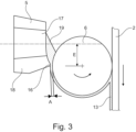
- the device 15 comprises a nozzle 5 with an outlet opening 17 from which the glue emerges and a roller 6 which is driven in a rotary motion in the direction of the arrow and onto which the glue emerging from the outlet opening 17 is applied in the form of a glue line 13.
- This glue line 13 is then applied or rubbed into the edge of the strip 2 by the roller 6.
- the roller 6 is driven anti-clockwise in the illustration, while the strip 2 is moved vertically downwards. This results in opposite movements of the strip 2 and the roller 6 at the right edge of the roller, i.e. at the edge of the roller 6 along which the strip 2 is guided.
- the relative speed between the strip 2 and the peripheral surface of the roller 6 is thus the sum of the transport speed of the strip 2 and the peripheral speed of the roller 6, and the glue is applied to the strip 2 at a correspondingly increased relative speed.
- the intermittent device 15 can be controlled so that the duration of the interruption of the glue supply as well as the start and end of the interruption of the glue supply are changed, while the remaining parameters remain constant.
- the nozzle 5 is arranged with the center of the outlet opening 17 offset by the dimension E upstream of the rotational movement of the opposite circumferential surface of the roller 6, i.e. opposite to the transport direction of the strip 2, eccentrically to the axis of rotation of the roller 6. Furthermore, the nozzle 5 has, on its lower edge 18 in the illustration, i.e. downstream in relation to the circumferential movement of the roller 6, an edge section 16 which projects in the direction of the roller 6 and which reduces the distance A between the edge 18 of the outlet opening 17 and the roller 6 and forms a narrow point. Through this narrow point, the glue is applied in a glue track 13 with a correspondingly reduced thickness to the circumferential surface of the roller 6 and is transported away by the roller 6 before it is applied to the strip 2 as a glue track 13.
- This deliberately formed glue reservoir 19, in conjunction with the intermittent glue supply through the nozzle 6, has the advantage that the length of the glue-free sections 14, particularly when using highly viscous glues with a viscosity of 230 mPas and in particular 1000 mPas and more, can be reduced to a length of 4 mm or less, which would otherwise not be possible with such a highly viscous glue at the high transport speed of the strip 2. This is achieved by initially deliberately building up the glue reservoir 19 during the glue supply.
- the glue is then applied from the glue reservoir 19 onto the roller 6 and via it onto the strip 2 until the glue reservoir 19 is also emptied. Only then does the application of glue to the strip 2 end, so that the temporal and spatial start of the glue-free section 14 on the strip 2 can be deliberately delayed further compared to the interruption of the glue supply.
- This time delay in turn depends on the volume of the glue reservoir 19, which in turn can be changed by reducing or increasing the distance A. Since the roller 6 is mounted with its axis of rotation in a fixed position and the strip 2 is arranged at a constant distance or in contact with the strip, there is also a change in the distance of the nozzle 5 to the strip 2. If the glue line 13 is applied directly to the strip 2 by the nozzle 5, the beginning and length of the glue-free sections 14 can be achieved in the same way by the formation and modification of the glue reservoir 19, which is formed directly between the nozzle 5 and the strip 2.
- the volume of the glue reservoir 19 and thus the time delay of the interruption of the glue application can be controlled by building up the glue reservoir 19 to a larger volume by reducing the distance A.
- the volume of the glue reservoir 19 and The glue application and thus the length of the glue-free sections 14 can also be controlled directly by changing the speed of the roller 6.
- the control of the length of the glue-free sections 14 by changing the distance A of the nozzle 5 to the roller 6 has the particular advantage that the length of the glue-free sections 14 can thereby be reduced to lengths of less than 4 mm, in particular to 2-3 mm, which is not possible solely by controlling the temporal interruption due to the inertia of the closing mechanism in the intermittent device 15 for mechanical reasons at the high transport speeds of the strip of 100 m/min and more, in particular of more than 400 m/min.
- Applying glue via the roller 6 shown has the additional advantage that the nozzle 5 does not come into contact with the strip 2 and is therefore not subject to wear. This is particularly advantageous because the nozzle 5 is a relatively expensive component, so that the costs for the maintenance of the production machine 1 can be reduced because the required replacement intervals of the nozzle 5 can be significantly extended.
- the application of glue via the roller 6 also enables a clean application of glue to very porous papers, and in particular the undesirable penetration of glue through the paper can be avoided.
- the application of glue from the nozzle 5 to the roller 6 is contactless, so that any amount of glue can be applied to the roller 6 in both height and width and finally further applied from the roller 6 to the strip 2.
- a glue quantity of 150 g/500 m can be applied to the strip 2, which is not possible by applying the glue directly to the strip 2 via the nozzle 5 in the desired quality.
- the application of the glue track 13 with the glue-free sections 14 counteracts the tendency of the formation of glue noses on the nozzle 5, since the nozzle 5 is practically “cleaned” due to the regular interruption of the glue supply at regular intervals by the "draining" of the glue reservoir 19 at its outlet opening.
- the glue line 13 can be very narrow and applied to one of the edges, so that the products 3 are only glued by a very narrow adhesive seam in a thin edge section of the overlapping edges. If a stronger adhesive seam or a stiffer product 3 is to be produced, the glue line 13 can also be applied wider up to the entire width, i.e. in a full-surface application, and the products 3 can in this case be fixed in shape with a smaller diameter by laying the edges on top of one another and gluing them to wider edge sections for greater dimensional stability.
Landscapes
- Making Paper Articles (AREA)
Applications Claiming Priority (2)
| Application Number | Priority Date | Filing Date | Title |
|---|---|---|---|
| DE102020102744.3A DE102020102744A1 (de) | 2020-02-04 | 2020-02-04 | Herstellmaschine zur Herstellung von stabförmigen Produkten aus einem endlosen Strang eines zu einem Rohr verklebten Streifens |
| PCT/EP2020/079908 WO2021155965A1 (de) | 2020-02-04 | 2020-10-23 | Herstellmaschine zur herstellung von stabförmigen produkten aus einem endlosen strang eines zu einem rohr verklebten streifens |
Publications (2)
| Publication Number | Publication Date |
|---|---|
| EP4100243A1 EP4100243A1 (de) | 2022-12-14 |
| EP4100243B1 true EP4100243B1 (de) | 2024-08-28 |
Family
ID=73037949
Family Applications (1)
| Application Number | Title | Priority Date | Filing Date |
|---|---|---|---|
| EP20799650.5A Active EP4100243B1 (de) | 2020-02-04 | 2020-10-23 | Herstellmaschine zur herstellung von stabförmigen produkten aus einem endlosen strang eines zu einem rohr verklebten streifens |
Country Status (6)
| Country | Link |
|---|---|
| US (1) | US12302941B2 (pl) |
| EP (1) | EP4100243B1 (pl) |
| CN (1) | CN115003495B (pl) |
| DE (1) | DE102020102744A1 (pl) |
| PL (1) | PL4100243T3 (pl) |
| WO (1) | WO2021155965A1 (pl) |
Families Citing this family (3)
| Publication number | Priority date | Publication date | Assignee | Title |
|---|---|---|---|---|
| DE102020102744A1 (de) | 2020-02-04 | 2021-08-05 | Hauni Maschinenbau Gmbh | Herstellmaschine zur Herstellung von stabförmigen Produkten aus einem endlosen Strang eines zu einem Rohr verklebten Streifens |
| DE102023123476A1 (de) * | 2023-08-31 | 2025-03-06 | Körber Technologies Gmbh | Vorrichtung und Verfahren zur Herstellung eines Filterstrangs, Verwendung eines Filterstrangs und HNB-Produkt |
| DE102024101817A1 (de) * | 2024-01-23 | 2025-07-24 | Körber Technologies Gmbh | Hohlröhrchenherstellung |
Citations (9)
| Publication number | Priority date | Publication date | Assignee | Title |
|---|---|---|---|---|
| US5531233A (en) * | 1994-06-22 | 1996-07-02 | R. J. Reynolds Tobacco Company | Method of and apparatus for applying adhesive to cigarette paper and the paper and cigarette produced thereby |
| DE19842266A1 (de) * | 1998-09-15 | 2000-03-16 | Windmoeller & Hoelscher | Verfahren zum Steuern von Klebstoffaufträgen auf kontinuierlich bewegte Sack- oder Beutelwerkstücke |
| US20040129281A1 (en) | 2001-06-27 | 2004-07-08 | Hancock Lloyd Harmon | Equipment and methods for manufacturing cigarettes |
| DE202012005938U1 (de) * | 2011-06-21 | 2012-07-10 | G.D S.P.A. | Leimauftragungseinheit für einen Hüllmaterialstreifen |
| EP2505993A2 (de) | 2011-04-01 | 2012-10-03 | Hauni Maschinenbau AG | Verfahren zur Ermittlung der Menge eines auf ein Hüllmaterial aufgetragenen fließfähigen Auftrags |
| EP2505269A2 (de) * | 2011-03-28 | 2012-10-03 | HAUNI Maschinenbau AG | Vorrichtung zum Beleimen eines bewegten Umhüllungsstreifens für stabförmige Produkte der Tabak verarbeitenden Industrie und Anlage mit einer derartigen Vorrichtung |
| DE102014213858B3 (de) | 2014-07-16 | 2015-11-12 | Hauni Maschinenbau Ag | Vorrichtung zum Auftragen einer Leimspur auf einen Umhüllungsstreifen eines stabförmigen Produktes der Tabak verarbeitenden Industrie |
| EP3354143A1 (de) | 2017-01-31 | 2018-08-01 | Hauni Maschinenbau GmbH | Verfahren und vorrichtung zum überwachen und herstellen eines filterstrangs der tabak verarbeitenden industrie |
| CN209789411U (zh) | 2018-11-08 | 2019-12-17 | 义乌市蒙特日用品有限公司 | 一种带勺型头的纸吸管 |
Family Cites Families (10)
| Publication number | Priority date | Publication date | Assignee | Title |
|---|---|---|---|---|
| EP1731045B1 (de) | 2000-04-20 | 2011-02-23 | Hauni Maschinenbau AG | Verfahren zum Auftragen von Leim auf ein Hüllmaterial eines stabförmigen Artikels der Tabak verarbeitenden Industrie |
| DE102005037086A1 (de) * | 2005-08-03 | 2007-02-08 | Hauni Maschinenbau Ag | Überwachung eines Leimbilds auf einem Umhüllungsstreifen |
| DE102012213338B4 (de) | 2012-07-30 | 2014-10-09 | Hauni Maschinenbau Ag | Verfahren und Vorrichtung zum Herstellen von Multisegmentfilterstäben der Tabak verarbeitenden Industrie |
| DE102012213337B4 (de) | 2012-07-30 | 2014-10-09 | Hauni Maschinenbau Ag | Verfahren und Vorrichtung zum Herstellen eines Multisegmentfilterstrangs der Tabak verarbeitenden Industrie |
| DE102013208399A1 (de) | 2013-05-07 | 2014-11-13 | Hauni Maschinenbau Ag | Vorrichtung zum Auftragen einer Leimspur auf einen Umhüllungsstreifen eines stabförmigen Produkts der Tabak verarbeitenden Industrie |
| CN103783663B (zh) | 2014-02-28 | 2015-09-09 | 川渝中烟工业有限责任公司 | 卷烟机水松纸自动对位控制装置 |
| DE102016107290A1 (de) | 2016-04-20 | 2017-10-26 | Hauni Maschinenbau Gmbh | Vorrichtung zum Auftragen einer Leimspur auf einen Umhüllungsstreifen eines stabförmigen Produktes der Tabak verarbeitenden Industrie |
| DE102018108289A1 (de) | 2018-04-09 | 2019-10-10 | Hauni Maschinenbau Gmbh | Vorrichtung und Verfahren zur Herstellung von stabförmigen Tabaksegmenten mit jeweils einem Heizstreifen |
| CN209649638U (zh) | 2019-03-19 | 2019-11-19 | 东莞市铭博自动化设备有限公司 | 纸吸管成型包装一体机的成型机构 |
| DE102020102744A1 (de) | 2020-02-04 | 2021-08-05 | Hauni Maschinenbau Gmbh | Herstellmaschine zur Herstellung von stabförmigen Produkten aus einem endlosen Strang eines zu einem Rohr verklebten Streifens |
-
2020
- 2020-02-04 DE DE102020102744.3A patent/DE102020102744A1/de active Pending
- 2020-10-23 PL PL20799650.5T patent/PL4100243T3/pl unknown
- 2020-10-23 US US17/797,228 patent/US12302941B2/en active Active
- 2020-10-23 EP EP20799650.5A patent/EP4100243B1/de active Active
- 2020-10-23 CN CN202080095589.1A patent/CN115003495B/zh active Active
- 2020-10-23 WO PCT/EP2020/079908 patent/WO2021155965A1/de not_active Ceased
Patent Citations (10)
| Publication number | Priority date | Publication date | Assignee | Title |
|---|---|---|---|---|
| US5531233A (en) * | 1994-06-22 | 1996-07-02 | R. J. Reynolds Tobacco Company | Method of and apparatus for applying adhesive to cigarette paper and the paper and cigarette produced thereby |
| DE19842266A1 (de) * | 1998-09-15 | 2000-03-16 | Windmoeller & Hoelscher | Verfahren zum Steuern von Klebstoffaufträgen auf kontinuierlich bewegte Sack- oder Beutelwerkstücke |
| ITMI991911A1 (it) * | 1998-09-15 | 2001-03-14 | Windmoeller & Hoelscher | Procedimento per il controllo di applicazioni di colla su elementi a sacco o sacchetto mossi in modo continuo |
| US20040129281A1 (en) | 2001-06-27 | 2004-07-08 | Hancock Lloyd Harmon | Equipment and methods for manufacturing cigarettes |
| EP2505269A2 (de) * | 2011-03-28 | 2012-10-03 | HAUNI Maschinenbau AG | Vorrichtung zum Beleimen eines bewegten Umhüllungsstreifens für stabförmige Produkte der Tabak verarbeitenden Industrie und Anlage mit einer derartigen Vorrichtung |
| EP2505993A2 (de) | 2011-04-01 | 2012-10-03 | Hauni Maschinenbau AG | Verfahren zur Ermittlung der Menge eines auf ein Hüllmaterial aufgetragenen fließfähigen Auftrags |
| DE202012005938U1 (de) * | 2011-06-21 | 2012-07-10 | G.D S.P.A. | Leimauftragungseinheit für einen Hüllmaterialstreifen |
| DE102014213858B3 (de) | 2014-07-16 | 2015-11-12 | Hauni Maschinenbau Ag | Vorrichtung zum Auftragen einer Leimspur auf einen Umhüllungsstreifen eines stabförmigen Produktes der Tabak verarbeitenden Industrie |
| EP3354143A1 (de) | 2017-01-31 | 2018-08-01 | Hauni Maschinenbau GmbH | Verfahren und vorrichtung zum überwachen und herstellen eines filterstrangs der tabak verarbeitenden industrie |
| CN209789411U (zh) | 2018-11-08 | 2019-12-17 | 义乌市蒙特日用品有限公司 | 一种带勺型头的纸吸管 |
Non-Patent Citations (1)
| Title |
|---|
| COPY OF GRANTED CLAIMS 1 AND 15 |
Also Published As
| Publication number | Publication date |
|---|---|
| US12302941B2 (en) | 2025-05-20 |
| US20230068917A1 (en) | 2023-03-02 |
| WO2021155965A1 (de) | 2021-08-12 |
| DE102020102744A1 (de) | 2021-08-05 |
| CN115003495A (zh) | 2022-09-02 |
| EP4100243A1 (de) | 2022-12-14 |
| CN115003495B (zh) | 2025-12-12 |
| PL4100243T3 (pl) | 2025-01-20 |
Similar Documents
| Publication | Publication Date | Title |
|---|---|---|
| EP1161887B1 (de) | Verfahren zum Aufbringen eines Fluides auf einen Umhüllungspapierstreifen | |
| EP3269265B1 (de) | Schneiden eines belagpapierstreifens der tabak verarbeitenden industrie | |
| DE102014213858B3 (de) | Vorrichtung zum Auftragen einer Leimspur auf einen Umhüllungsstreifen eines stabförmigen Produktes der Tabak verarbeitenden Industrie | |
| EP4100243B1 (de) | Herstellmaschine zur herstellung von stabförmigen produkten aus einem endlosen strang eines zu einem rohr verklebten streifens | |
| EP3453501B1 (de) | Verbindungsschnittanordnung | |
| EP1891865B1 (de) | Papierbeleimung bei der Strangherstellung | |
| DE602004008448T2 (de) | Die materialanwendung von stäbchenverpackungen betreffende verbesserungen | |
| DE10208741B4 (de) | Gerät zum Zuführen von Rohmaterial in konstanten Mengen | |
| EP2505269A2 (de) | Vorrichtung zum Beleimen eines bewegten Umhüllungsstreifens für stabförmige Produkte der Tabak verarbeitenden Industrie und Anlage mit einer derartigen Vorrichtung | |
| EP3235388B2 (de) | Vorrichtung zum auftragen einer leimspur auf einen umhüllungsstreifen eines stabförmigen produktes der tabak verarbeitenden industrie | |
| EP3822019B1 (de) | Vorrichtung und verfahren zum aufbringen einer materialschicht auf einen oberflächenbereich eines werkstücks | |
| EP3381303A1 (de) | Verfahren zum herstellen von wenigstens doppellagigen rohrförmigen strängen der tabak verarbeitenden industrie sowie vorrichtung zur herstellung von wenigstens doppellagigen strängen der tabak verarbeitenden industrie | |
| EP2625972A2 (de) | Fördereinrichtung zum Fördern stabförmiger Produkte der Tabak verarbeitenden Industrie und Verfahren zur Steuerung einer derartigen Fördervorrichtung | |
| EP2510791A2 (de) | Vorrichtung zur Formung eines Teigbandes aus zugeführten Teigportionen | |
| EP1442665A1 (de) | Verfahren zum Beleimen einer bewegten Bahn, sowie Vorrichtung, insbesondere zur Durchführung des Verfahrens | |
| EP2401928A2 (de) | Einrichtung zur Herstellung von stabförmigen Produkten der Tabak verarbeitenden Industrie | |
| EP3056097B1 (de) | Vorrichtung zur herstellung von produkten der tabak verarbeitenden industrie | |
| WO2022128797A1 (de) | Vorrichtung und verfahren zur herstellung eines stab- oder rohrförmigen artikels sowie stab- oder rohrförmiges produkt | |
| EP2074895A1 (de) | Belageinrichtung einer Maschine der Tabak verarbeitenden Industrie | |
| EP0975434B1 (de) | Leimwerk für eine wellpappenanlage | |
| DE3744107C2 (pl) | ||
| EP1817159B1 (de) | Verfahren und vorrichtung zum klebstoffauftrag auf wellpappe | |
| EP2801266A2 (de) | Vorrichtung zum Auftragen einer Leimspur auf einen Umhüllungsstreifen eines stabförmigen Produkts der Tabak verarbeitenden Industrie | |
| DE102005001471A1 (de) | Schneidvorrichtung | |
| EP3318138A1 (de) | Vorrichtung und verfahren zum fördern einer materialbahn der tabak verarbeitenden industrie |
Legal Events
| Date | Code | Title | Description |
|---|---|---|---|
| STAA | Information on the status of an ep patent application or granted ep patent |
Free format text: STATUS: UNKNOWN |
|
| STAA | Information on the status of an ep patent application or granted ep patent |
Free format text: STATUS: THE INTERNATIONAL PUBLICATION HAS BEEN MADE |
|
| PUAI | Public reference made under article 153(3) epc to a published international application that has entered the european phase |
Free format text: ORIGINAL CODE: 0009012 |
|
| STAA | Information on the status of an ep patent application or granted ep patent |
Free format text: STATUS: REQUEST FOR EXAMINATION WAS MADE |
|
| 17P | Request for examination filed |
Effective date: 20220818 |
|
| AK | Designated contracting states |
Kind code of ref document: A1 Designated state(s): AL AT BE BG CH CY CZ DE DK EE ES FI FR GB GR HR HU IE IS IT LI LT LU LV MC MK MT NL NO PL PT RO RS SE SI SK SM TR |
|
| RAP3 | Party data changed (applicant data changed or rights of an application transferred) |
Owner name: KOERBER TECHNOLOGIES GMBH |
|
| TPAC | Observations filed by third parties |
Free format text: ORIGINAL CODE: EPIDOSNTIPA |
|
| TPAC | Observations filed by third parties |
Free format text: ORIGINAL CODE: EPIDOSNTIPA |
|
| DAV | Request for validation of the european patent (deleted) | ||
| DAX | Request for extension of the european patent (deleted) | ||
| STAA | Information on the status of an ep patent application or granted ep patent |
Free format text: STATUS: EXAMINATION IS IN PROGRESS |
|
| 17Q | First examination report despatched |
Effective date: 20230802 |
|
| P01 | Opt-out of the competence of the unified patent court (upc) registered |
Effective date: 20231001 |
|
| RIC1 | Information provided on ipc code assigned before grant |
Ipc: A24C 5/46 20060101ALI20240209BHEP Ipc: A47G 21/18 20060101ALI20240209BHEP Ipc: B31D 5/00 20170101ALI20240209BHEP Ipc: B31C 5/00 20060101AFI20240209BHEP |
|
| GRAP | Despatch of communication of intention to grant a patent |
Free format text: ORIGINAL CODE: EPIDOSNIGR1 |
|
| STAA | Information on the status of an ep patent application or granted ep patent |
Free format text: STATUS: GRANT OF PATENT IS INTENDED |
|
| INTG | Intention to grant announced |
Effective date: 20240325 |
|
| GRAS | Grant fee paid |
Free format text: ORIGINAL CODE: EPIDOSNIGR3 |
|
| GRAA | (expected) grant |
Free format text: ORIGINAL CODE: 0009210 |
|
| STAA | Information on the status of an ep patent application or granted ep patent |
Free format text: STATUS: THE PATENT HAS BEEN GRANTED |
|
| AK | Designated contracting states |
Kind code of ref document: B1 Designated state(s): AL AT BE BG CH CY CZ DE DK EE ES FI FR GB GR HR HU IE IS IT LI LT LU LV MC MK MT NL NO PL PT RO RS SE SI SK SM TR |
|
| REG | Reference to a national code |
Ref country code: CH Ref legal event code: EP |
|
| REG | Reference to a national code |
Ref country code: DE Ref legal event code: R096 Ref document number: 502020009060 Country of ref document: DE |
|
| REG | Reference to a national code |
Ref country code: IE Ref legal event code: FG4D Free format text: LANGUAGE OF EP DOCUMENT: GERMAN |
|
| REG | Reference to a national code |
Ref country code: NL Ref legal event code: FP |
|
| REG | Reference to a national code |
Ref country code: LT Ref legal event code: MG9D |
|
| PG25 | Lapsed in a contracting state [announced via postgrant information from national office to epo] |
Ref country code: NO Free format text: LAPSE BECAUSE OF FAILURE TO SUBMIT A TRANSLATION OF THE DESCRIPTION OR TO PAY THE FEE WITHIN THE PRESCRIBED TIME-LIMIT Effective date: 20241128 |
|
| PG25 | Lapsed in a contracting state [announced via postgrant information from national office to epo] |
Ref country code: PT Free format text: LAPSE BECAUSE OF FAILURE TO SUBMIT A TRANSLATION OF THE DESCRIPTION OR TO PAY THE FEE WITHIN THE PRESCRIBED TIME-LIMIT Effective date: 20241230 Ref country code: FI Free format text: LAPSE BECAUSE OF FAILURE TO SUBMIT A TRANSLATION OF THE DESCRIPTION OR TO PAY THE FEE WITHIN THE PRESCRIBED TIME-LIMIT Effective date: 20240828 Ref country code: GR Free format text: LAPSE BECAUSE OF FAILURE TO SUBMIT A TRANSLATION OF THE DESCRIPTION OR TO PAY THE FEE WITHIN THE PRESCRIBED TIME-LIMIT Effective date: 20241129 |
|
| PG25 | Lapsed in a contracting state [announced via postgrant information from national office to epo] |
Ref country code: BG Free format text: LAPSE BECAUSE OF FAILURE TO SUBMIT A TRANSLATION OF THE DESCRIPTION OR TO PAY THE FEE WITHIN THE PRESCRIBED TIME-LIMIT Effective date: 20240828 |
|
| PG25 | Lapsed in a contracting state [announced via postgrant information from national office to epo] |
Ref country code: LV Free format text: LAPSE BECAUSE OF FAILURE TO SUBMIT A TRANSLATION OF THE DESCRIPTION OR TO PAY THE FEE WITHIN THE PRESCRIBED TIME-LIMIT Effective date: 20240828 |
|
| PG25 | Lapsed in a contracting state [announced via postgrant information from national office to epo] |
Ref country code: IS Free format text: LAPSE BECAUSE OF FAILURE TO SUBMIT A TRANSLATION OF THE DESCRIPTION OR TO PAY THE FEE WITHIN THE PRESCRIBED TIME-LIMIT Effective date: 20241228 |
|
| PG25 | Lapsed in a contracting state [announced via postgrant information from national office to epo] |
Ref country code: HR Free format text: LAPSE BECAUSE OF FAILURE TO SUBMIT A TRANSLATION OF THE DESCRIPTION OR TO PAY THE FEE WITHIN THE PRESCRIBED TIME-LIMIT Effective date: 20240828 |
|
| PG25 | Lapsed in a contracting state [announced via postgrant information from national office to epo] |
Ref country code: ES Free format text: LAPSE BECAUSE OF FAILURE TO SUBMIT A TRANSLATION OF THE DESCRIPTION OR TO PAY THE FEE WITHIN THE PRESCRIBED TIME-LIMIT Effective date: 20240828 Ref country code: RS Free format text: LAPSE BECAUSE OF FAILURE TO SUBMIT A TRANSLATION OF THE DESCRIPTION OR TO PAY THE FEE WITHIN THE PRESCRIBED TIME-LIMIT Effective date: 20241128 |
|
| PG25 | Lapsed in a contracting state [announced via postgrant information from national office to epo] |
Ref country code: RS Free format text: LAPSE BECAUSE OF FAILURE TO SUBMIT A TRANSLATION OF THE DESCRIPTION OR TO PAY THE FEE WITHIN THE PRESCRIBED TIME-LIMIT Effective date: 20241128 Ref country code: PT Free format text: LAPSE BECAUSE OF FAILURE TO SUBMIT A TRANSLATION OF THE DESCRIPTION OR TO PAY THE FEE WITHIN THE PRESCRIBED TIME-LIMIT Effective date: 20241230 Ref country code: NO Free format text: LAPSE BECAUSE OF FAILURE TO SUBMIT A TRANSLATION OF THE DESCRIPTION OR TO PAY THE FEE WITHIN THE PRESCRIBED TIME-LIMIT Effective date: 20241128 Ref country code: LV Free format text: LAPSE BECAUSE OF FAILURE TO SUBMIT A TRANSLATION OF THE DESCRIPTION OR TO PAY THE FEE WITHIN THE PRESCRIBED TIME-LIMIT Effective date: 20240828 Ref country code: IS Free format text: LAPSE BECAUSE OF FAILURE TO SUBMIT A TRANSLATION OF THE DESCRIPTION OR TO PAY THE FEE WITHIN THE PRESCRIBED TIME-LIMIT Effective date: 20241228 Ref country code: HR Free format text: LAPSE BECAUSE OF FAILURE TO SUBMIT A TRANSLATION OF THE DESCRIPTION OR TO PAY THE FEE WITHIN THE PRESCRIBED TIME-LIMIT Effective date: 20240828 Ref country code: GR Free format text: LAPSE BECAUSE OF FAILURE TO SUBMIT A TRANSLATION OF THE DESCRIPTION OR TO PAY THE FEE WITHIN THE PRESCRIBED TIME-LIMIT Effective date: 20241129 Ref country code: FI Free format text: LAPSE BECAUSE OF FAILURE TO SUBMIT A TRANSLATION OF THE DESCRIPTION OR TO PAY THE FEE WITHIN THE PRESCRIBED TIME-LIMIT Effective date: 20240828 Ref country code: ES Free format text: LAPSE BECAUSE OF FAILURE TO SUBMIT A TRANSLATION OF THE DESCRIPTION OR TO PAY THE FEE WITHIN THE PRESCRIBED TIME-LIMIT Effective date: 20240828 Ref country code: BG Free format text: LAPSE BECAUSE OF FAILURE TO SUBMIT A TRANSLATION OF THE DESCRIPTION OR TO PAY THE FEE WITHIN THE PRESCRIBED TIME-LIMIT Effective date: 20240828 |
|
| PG25 | Lapsed in a contracting state [announced via postgrant information from national office to epo] |
Ref country code: DK Free format text: LAPSE BECAUSE OF FAILURE TO SUBMIT A TRANSLATION OF THE DESCRIPTION OR TO PAY THE FEE WITHIN THE PRESCRIBED TIME-LIMIT Effective date: 20240828 Ref country code: SM Free format text: LAPSE BECAUSE OF FAILURE TO SUBMIT A TRANSLATION OF THE DESCRIPTION OR TO PAY THE FEE WITHIN THE PRESCRIBED TIME-LIMIT Effective date: 20240828 Ref country code: RO Free format text: LAPSE BECAUSE OF FAILURE TO SUBMIT A TRANSLATION OF THE DESCRIPTION OR TO PAY THE FEE WITHIN THE PRESCRIBED TIME-LIMIT Effective date: 20240828 |
|
| PG25 | Lapsed in a contracting state [announced via postgrant information from national office to epo] |
Ref country code: EE Free format text: LAPSE BECAUSE OF FAILURE TO SUBMIT A TRANSLATION OF THE DESCRIPTION OR TO PAY THE FEE WITHIN THE PRESCRIBED TIME-LIMIT Effective date: 20240828 |
|
| PG25 | Lapsed in a contracting state [announced via postgrant information from national office to epo] |
Ref country code: CZ Free format text: LAPSE BECAUSE OF FAILURE TO SUBMIT A TRANSLATION OF THE DESCRIPTION OR TO PAY THE FEE WITHIN THE PRESCRIBED TIME-LIMIT Effective date: 20240828 |
|
| PG25 | Lapsed in a contracting state [announced via postgrant information from national office to epo] |
Ref country code: SK Free format text: LAPSE BECAUSE OF FAILURE TO SUBMIT A TRANSLATION OF THE DESCRIPTION OR TO PAY THE FEE WITHIN THE PRESCRIBED TIME-LIMIT Effective date: 20240828 |
|
| REG | Reference to a national code |
Ref country code: DE Ref legal event code: R026 Ref document number: 502020009060 Country of ref document: DE |
|
| PLBI | Opposition filed |
Free format text: ORIGINAL CODE: 0009260 |
|
| REG | Reference to a national code |
Ref country code: CH Ref legal event code: PL |
|
| PLAB | Opposition data, opponent's data or that of the opponent's representative modified |
Free format text: ORIGINAL CODE: 0009299OPPO |
|
| PLAX | Notice of opposition and request to file observation + time limit sent |
Free format text: ORIGINAL CODE: EPIDOSNOBS2 |
|
| 26 | Opposition filed |
Opponent name: G.D S.P.A. Effective date: 20250528 |
|
| PG25 | Lapsed in a contracting state [announced via postgrant information from national office to epo] |
Ref country code: MC Free format text: LAPSE BECAUSE OF FAILURE TO SUBMIT A TRANSLATION OF THE DESCRIPTION OR TO PAY THE FEE WITHIN THE PRESCRIBED TIME-LIMIT Effective date: 20240828 |
|
| R26 | Opposition filed (corrected) |
Opponent name: G.D S.P.A. Effective date: 20250528 |
|
| PG25 | Lapsed in a contracting state [announced via postgrant information from national office to epo] |
Ref country code: BE Free format text: LAPSE BECAUSE OF NON-PAYMENT OF DUE FEES Effective date: 20241031 Ref country code: LU Free format text: LAPSE BECAUSE OF NON-PAYMENT OF DUE FEES Effective date: 20241023 |
|
| PG25 | Lapsed in a contracting state [announced via postgrant information from national office to epo] |
Ref country code: FR Free format text: LAPSE BECAUSE OF NON-PAYMENT OF DUE FEES Effective date: 20241028 |
|
| GBPC | Gb: european patent ceased through non-payment of renewal fee |
Effective date: 20241128 |
|
| PG25 | Lapsed in a contracting state [announced via postgrant information from national office to epo] |
Ref country code: CH Free format text: LAPSE BECAUSE OF NON-PAYMENT OF DUE FEES Effective date: 20241031 |
|
| REG | Reference to a national code |
Ref country code: BE Ref legal event code: MM Effective date: 20241031 |
|
| PG25 | Lapsed in a contracting state [announced via postgrant information from national office to epo] |
Ref country code: SE Free format text: LAPSE BECAUSE OF FAILURE TO SUBMIT A TRANSLATION OF THE DESCRIPTION OR TO PAY THE FEE WITHIN THE PRESCRIBED TIME-LIMIT Effective date: 20240828 |
|
| PLBB | Reply of patent proprietor to notice(s) of opposition received |
Free format text: ORIGINAL CODE: EPIDOSNOBS3 |
|
| PGFP | Annual fee paid to national office [announced via postgrant information from national office to epo] |
Ref country code: PL Payment date: 20250925 Year of fee payment: 6 |
|
| PG25 | Lapsed in a contracting state [announced via postgrant information from national office to epo] |
Ref country code: GB Free format text: LAPSE BECAUSE OF NON-PAYMENT OF DUE FEES Effective date: 20241128 |
|
| PG25 | Lapsed in a contracting state [announced via postgrant information from national office to epo] |
Ref country code: IE Free format text: LAPSE BECAUSE OF NON-PAYMENT OF DUE FEES Effective date: 20241023 |
|
| PGFP | Annual fee paid to national office [announced via postgrant information from national office to epo] |
Ref country code: NL Payment date: 20251024 Year of fee payment: 6 |
|
| PGFP | Annual fee paid to national office [announced via postgrant information from national office to epo] |
Ref country code: DE Payment date: 20251030 Year of fee payment: 6 |
|
| PGFP | Annual fee paid to national office [announced via postgrant information from national office to epo] |
Ref country code: AT Payment date: 20260113 Year of fee payment: 5 |
|
| PGFP | Annual fee paid to national office [announced via postgrant information from national office to epo] |
Ref country code: IT Payment date: 20251030 Year of fee payment: 6 |
|
| PG25 | Lapsed in a contracting state [announced via postgrant information from national office to epo] |
Ref country code: CY Free format text: LAPSE BECAUSE OF FAILURE TO SUBMIT A TRANSLATION OF THE DESCRIPTION OR TO PAY THE FEE WITHIN THE PRESCRIBED TIME-LIMIT; INVALID AB INITIO Effective date: 20201023 |
|
| PG25 | Lapsed in a contracting state [announced via postgrant information from national office to epo] |
Ref country code: HU Free format text: LAPSE BECAUSE OF FAILURE TO SUBMIT A TRANSLATION OF THE DESCRIPTION OR TO PAY THE FEE WITHIN THE PRESCRIBED TIME-LIMIT; INVALID AB INITIO Effective date: 20201023 |