EP4100193B1 - Sieb zur verwendung beim löten von wärmetauschern und lötverfahren für wärmetauscher - Google Patents
Sieb zur verwendung beim löten von wärmetauschern und lötverfahren für wärmetauscher Download PDFInfo
- Publication number
- EP4100193B1 EP4100193B1 EP21701790.4A EP21701790A EP4100193B1 EP 4100193 B1 EP4100193 B1 EP 4100193B1 EP 21701790 A EP21701790 A EP 21701790A EP 4100193 B1 EP4100193 B1 EP 4100193B1
- Authority
- EP
- European Patent Office
- Prior art keywords
- screen
- brazing
- base plate
- core plates
- heat exchanger
- Prior art date
- Legal status (The legal status is an assumption and is not a legal conclusion. Google has not performed a legal analysis and makes no representation as to the accuracy of the status listed.)
- Active
Links
Images


Classifications
-
- B—PERFORMING OPERATIONS; TRANSPORTING
- B23—MACHINE TOOLS; METAL-WORKING NOT OTHERWISE PROVIDED FOR
- B23K—SOLDERING OR UNSOLDERING; WELDING; CLADDING OR PLATING BY SOLDERING OR WELDING; CUTTING BY APPLYING HEAT LOCALLY, e.g. FLAME CUTTING; WORKING BY LASER BEAM
- B23K1/00—Soldering, e.g. brazing, or unsoldering
- B23K1/0008—Soldering, e.g. brazing, or unsoldering specially adapted for particular articles or work
- B23K1/0012—Brazing heat exchangers
-
- B—PERFORMING OPERATIONS; TRANSPORTING
- B23—MACHINE TOOLS; METAL-WORKING NOT OTHERWISE PROVIDED FOR
- B23K—SOLDERING OR UNSOLDERING; WELDING; CLADDING OR PLATING BY SOLDERING OR WELDING; CUTTING BY APPLYING HEAT LOCALLY, e.g. FLAME CUTTING; WORKING BY LASER BEAM
- B23K1/00—Soldering, e.g. brazing, or unsoldering
- B23K1/008—Soldering within a furnace
-
- B—PERFORMING OPERATIONS; TRANSPORTING
- B23—MACHINE TOOLS; METAL-WORKING NOT OTHERWISE PROVIDED FOR
- B23K—SOLDERING OR UNSOLDERING; WELDING; CLADDING OR PLATING BY SOLDERING OR WELDING; CUTTING BY APPLYING HEAT LOCALLY, e.g. FLAME CUTTING; WORKING BY LASER BEAM
- B23K3/00—Tools, devices, or special appurtenances for soldering, e.g. brazing, or unsoldering, not specially adapted for particular methods
- B23K3/08—Auxiliary devices therefor
- B23K3/087—Soldering or brazing jigs, fixtures or clamping means
-
- F—MECHANICAL ENGINEERING; LIGHTING; HEATING; WEAPONS; BLASTING
- F28—HEAT EXCHANGE IN GENERAL
- F28D—HEAT-EXCHANGE APPARATUS, NOT PROVIDED FOR IN ANOTHER SUBCLASS, IN WHICH THE HEAT-EXCHANGE MEDIA DO NOT COME INTO DIRECT CONTACT
- F28D9/00—Heat-exchange apparatus having stationary plate-like or laminated conduit assemblies for both heat-exchange media, the media being in contact with different sides of a conduit wall
- F28D9/0031—Heat-exchange apparatus having stationary plate-like or laminated conduit assemblies for both heat-exchange media, the media being in contact with different sides of a conduit wall the conduits for one heat-exchange medium being formed by paired plates touching each other
- F28D9/0043—Heat-exchange apparatus having stationary plate-like or laminated conduit assemblies for both heat-exchange media, the media being in contact with different sides of a conduit wall the conduits for one heat-exchange medium being formed by paired plates touching each other the plates having openings therein for circulation of at least one heat-exchange medium from one conduit to another
- F28D9/005—Heat-exchange apparatus having stationary plate-like or laminated conduit assemblies for both heat-exchange media, the media being in contact with different sides of a conduit wall the conduits for one heat-exchange medium being formed by paired plates touching each other the plates having openings therein for circulation of at least one heat-exchange medium from one conduit to another the plates having openings therein for both heat-exchange media
-
- B—PERFORMING OPERATIONS; TRANSPORTING
- B23—MACHINE TOOLS; METAL-WORKING NOT OTHERWISE PROVIDED FOR
- B23K—SOLDERING OR UNSOLDERING; WELDING; CLADDING OR PLATING BY SOLDERING OR WELDING; CUTTING BY APPLYING HEAT LOCALLY, e.g. FLAME CUTTING; WORKING BY LASER BEAM
- B23K2101/00—Articles made by soldering, welding or cutting
- B23K2101/04—Tubular or hollow articles
- B23K2101/14—Heat exchangers
-
- F—MECHANICAL ENGINEERING; LIGHTING; HEATING; WEAPONS; BLASTING
- F28—HEAT EXCHANGE IN GENERAL
- F28D—HEAT-EXCHANGE APPARATUS, NOT PROVIDED FOR IN ANOTHER SUBCLASS, IN WHICH THE HEAT-EXCHANGE MEDIA DO NOT COME INTO DIRECT CONTACT
- F28D21/00—Heat-exchange apparatus not covered by any of the groups F28D1/00 - F28D20/00
- F28D2021/0019—Other heat exchangers for particular applications; Heat exchange systems not otherwise provided for
- F28D2021/008—Other heat exchangers for particular applications; Heat exchange systems not otherwise provided for for vehicles
- F28D2021/0089—Oil coolers
-
- F—MECHANICAL ENGINEERING; LIGHTING; HEATING; WEAPONS; BLASTING
- F28—HEAT EXCHANGE IN GENERAL
- F28F—DETAILS OF HEAT-EXCHANGE AND HEAT-TRANSFER APPARATUS, OF GENERAL APPLICATION
- F28F2275/00—Fastening; Joining
- F28F2275/04—Fastening; Joining by brazing
Definitions
- the present invention relates to art for manufacturing a heat exchanger assembled by brazing using a brazing sheet composed of an aluminum alloy cladded material, and in particular, relates to a screen used while brazing and to a brazing method using the same, see claims 1 and 8.
- a heat exchanger used as an oil cooler or the like in a vehicle is generally constituted from an aluminum alloy in consideration of thermal conductivity, specific weight, formability, and the like, and many methods are employed wherein a brazing sheet composed of a cladded material having a brazing material layer having a relatively low melting point provided on the surface is used to form a plurality of members, and once these members are temporarily assembled they are heated in a furnace and integrally brazed.
- Brazing construction methods largely are broadly categorized as so-called CAB methods (Control Atmosphere Brazing) performed under atmospheric pressure using an inert gas (nitrogen, argon, or the like) and utilizing a fluoride based flux, and so-called VB methods (Vacuum Brazing Method) performed under high vacuum and not utilizing flux.
- CAB methods Control Atmosphere Brazing
- VB methods Vauum Brazing Method
- a workpiece to be brazed is coated in advance with a non-corrosive fluoride based flux, whereby an oxide film on the surface of the brazing material layer of the brazing sheet can be broken down during brazing. Accordingly, a melted brazing material spreads into an interstice between members due to surface tension and a bond between the members is formed.
- an aluminum alloy containing Mg is used as the brazing material layer or core material of the cladded material, or otherwise Mg is placed inside a furnace separate from the workpiece, and brazing is performed under a high vacuum. Heating the Mg in the furnace breaks down the oxide film on the surface of the brazing material layer of the brazing sheet, and the evaporated Mg captures traces of oxygen and moisture which are brazing inhibitory substances which exist near the surface. Accordingly, brazing that does not utilize flux is possible.
- CAB methods performed under atmospheric pressure have comparatively short formation cycle times and comparatively inexpensive equipment costs, but there are many drawbacks associated with using flux such as requiring a flux coating process, a flex residue cleaning process, or the like.
- VB methods do not have problems relating to flux, but mass-productivity is low due to batch processing using vacuum furnaces, and the equipment can easily become very costly.
- patent documents 1 and 2 propose covering the workpiece using a metal cover-shaped member to enable brazing of an aluminum alloy brazing sheet without using flux and without needing a high vacuum.
- Patent document 1 teaches a configuration wherein a workpiece is configured using an aluminum alloy brazing sheet containing Mg, and the workpiece is warmed to near the melting point of the brazing material inside a furnace, at which point the workpiece is covered by a cover-shaped windscreen jig.
- the windscreen jig is configured so as to be used in circulation inside the furnace.
- patent document 2 discloses using an aluminum alloy brazing sheet containing Mg or using a separate Mg supply source to overlay the cover-shaped cover onto the workpiece before heating.
- the cover has a box-shaped configuration wherein a hole is opened in the center of the ceiling face.
- patent document 2 has a configuration wherein the cover is placed over a support stand for the workpiece provided inside the furnace; as such, the strict management of gaps between the cover and the workpiece is difficult and the operation process for attaching and detaching the cover inside the furnace is troublesome.
- the present invention is to provide a screen to be used when brazing a heat exchanger having a plurality of core plates formed from an aluminum alloy brazing sheet containing Mg and formed in a shape having a taper portion at the periphery which are stacked such that the taper portions touch together and are heated and brazed under an inert gas atmosphere together with a base plate on the lower face side which is larger and thicker than the core plates.
- a screen to be used when brazing a heat exchanger according to a first aspect of the present invention is defined in claim 1.
- a brazing method for a heat exchanger using such screen according to a second aspect of the present invention is defined in claim 8.
- the screen is formed from a metal sheet as a tube enclosing a stacked body of the core plates, follows the outer border of the core plates such that the inner wall face of the tube has a specific minute gap between it and the tip edge of the taper portion, and is mounted onto the base plate.
- the Mg contained in the brazing sheet breaks down the aluminum oxide film on the brazing sheet surface which causes brazing to be difficult. Furthermore, due to the stacked body of core plates, which is the workpiece, being enclosed by the screen of the present invention, Mg that is vaporized from the brazing sheet as it is heated does not disperse into the atmosphere but remains near the perimeter of the core plates, and this Mg captures oxygen and moisture which hinder brazing properties. Therefore, it is possible to braze a heat exchanger without using flux and without a vacuum furnace. Specifically, the brazing properties are improved for taper portions on the periphery which are in a form such that they are exposed to the atmosphere during brazing.
- the stacked body of core plates that form a primary part of the heat exchanger are stacked onto a base plate that is larger and thicker than the core plates, and the screen is set so as to enclose the stacked body of core plates and is mounted onto the base plate.
- the screen is supported by the base plate, which is a portion of the workpiece sent into and out of the furnace, and the screen is conveyed having become integrated with the workpiece. Accordingly, it is easy to manage the minute gap between the core plates and the screen, and the screen becomes easy to handle, including sending into and out of the furnace.
- the gap between the stacked body of core plates and the inner wall face of the screen can be more precise. Furthermore, using the locating pins for both locating the stacked body of core plates and locating the screen reduces the number of components.
- a second base plate smaller than the first base plate is superimposed on the base plate, and the screen is located using the periphery of the second base plate.
- a relatively small second base plate is superimposed on the base plate to produce a step, and the screen is located using this step.
- the minute gap is at least 0.5 mm and no more than 5 mm.
- the Mg contained in the brazing sheet is generally a minute amount, and therefore, if the gap between the stacked body of core plates and the screen inner wall face is large, the vaporized Mg will diffuse into the atmosphere and will not sufficiently capture oxygen and moisture near the brazing location. Therefore, it is desirable for the gap to be no more than 5 mm.
- a brim portion covering the upper end of the minute gap is provided on the upper end of the tube portion enclosing the stacked body of core plates. Due to this brim portion, diffusion of vaporized Mg in the upward direction is effectively restricted.
- the screen is configured separated into a plurality of pieces so as to enclose, from the perimeter, the stacked body of core plates assembled on the base plate.
- the screen is configured separated in two into a first half portion and a second half portion so as to sandwich, from both sides, the stacked body of core plates assembled on the base plate.
- the edge portion of one extends, being offset to the outside only by the plate thickness, and overlaps together with the other edge portion located on the inside. Accordingly, the inner wall face of the tube is substantially continuous in the circumferential direction without any steps.
- the screen is preferable for the screen to be formed from a metal material having a coefficient of thermal expansion of at least 11 ⁇ 10 -6 and a melting point of at least 650 °C.
- the coefficient of thermal expansion of the aluminum alloy material forming the brazing sheet and the base plate is, for example, approximately 23 ⁇ 10 -6 , and it is preferable to have a small difference between the coefficient of thermal expansion for these and the coefficient of thermal expansion of the screen.
- a second invention is a brazing method for a heat exchanger using a screen as described above (see claim 8), including:
- Using the screen according to the present invention enables brazing of a heat exchanger using an aluminum alloy brazing sheet to be performed without flux and without a vacuum furnace, and the various problems associated with flux and problems related to vacuum furnaces can be avoided.
- the screen is conveyed together with the workpiece while mounted on the base plate, which is a portion of the workpiece, and therefore there are no additional complicated processes or expensive equipment.
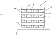
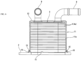
- FIG. 1 is a cross sectional descriptive view schematically illustrating a configuration of a heat exchanger 1 applicable to the present invention.
- This heat exchanger 1 is, for example, an oil cooler for cooling lubricating oil for an internal combustion engine for a vehicle using heat exchange with a coolant.
- the terms "up” and “down” are used hereinafter and are based on the orientation in FIG. 1 , which is the orientation at the time of brazing, but it is not limited to the orientation of FIG. 1 during use of an actual oil cooler.
- the heat exchanger 1 is configured by mounting a stacked body, or in other words, a core portion 3, onto a base plate 2 shaped as a comparatively thick plate, the stacked body being composed by stacking a plurality of thin sheet core plates 4 together with fin plates 5.
- each constituent elements of the heat exchanger 1 are all constituted of an aluminum based material, and each part is integrally brazed together by heating inside a furnace while held by a jig after assembling each part in a predetermined state.
- the core plates 4 are formed by an aluminum alloy brazing sheet composed of a cladded material provided with a brazing material layer on both faces thereof. This brazing sheet contains a minute amount of Mg in order to achieve brazing without using flux. The brazing sheet will be described in further detail below.
- the core portion 3 is configured such that a plurality of core plates 4 having a dish shape wherein the basic shape forms identical rectangles are stacked together with fin plates 5 to alternatingly configure a oil paths 6 and coolant paths 7 between two adjacent core plates 4.
- the fin plates 5 are disposed in the oil paths 6. Note that this type of heat exchanger 1 is a configuration that is substantially well known as disclosed in JP 2011-007411 A , JP 2013-007516 , and the like.
- the core plates 4 formed of a brazing sheet are configured having a taper portion 4a which stands up obliquely at the periphery, and when each core plate 4 is stacked in the vertical direction, each taper portion 4a mutually overlap and are tight together. Moreover, brazing together the taper portion 4a of each core plate 4 overlapping in this manner seals the perimeter of the oil paths 6 and coolant paths 7 in each level and the heat exchanger 1 is entirely integrated. Furthermore, the fin plates 5 are brazed to the surfaces of the core plates 4 inside the oil paths 6. Similarly, the bottom face of the bottom-most core plate 4 is brazed to the base plate 2.
- the base plate 2 also functions as an installation part for installing the heat exchanger 1 at a desired location, and is configured to be larger than the core plates 4 so as to protrude to the perimeter from the core portion 3, and is a plate member thicker than the core plates 4.
- Brazing is performed without using flux. Furthermore, brazing is performed without using a high vacuum vacuum-furnace as in conventional VB methods, and is performed at a pressure substantially near atmospheric pressure under an inert gas atmosphere such as nitrogen or argon. In other words, brazing is performed following the CAB method but without using flux. In one preferable example, brazing may be performed by using a continuous furnace for continuously performing a heating processing while conveying the workpiece.
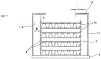
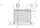
- a screen 11 of the present invention schematically illustrated in FIG. 2 overlays the workpiece. Due to this screen 11, Mg vaporized from the brazing sheet does not disperse into the atmosphere but remains near the core portion 3 (that is, the stacked body of core plates 4), and this Mg captures oxygen and moisture near the brazing surface which hinder brazing properties.
- a brim portion 12 covering the upper end of the minute gap D is provided on the upper end of the tube portion enclosing the core portion 3. It is desirable for the gap h between the topmost portion of the core portion 3 (for example, the topmost tip of the taper portion 4a), which the brim portion 12 opposes, and the lower face of the brim portion 12 to be no more than 5 mm.
- the overlapping margin L of the brim portion 12 and the core portion 3 periphery is at least 0 mm. In other words, when viewed from above as a projection, at least the brim portion 12 and the core portion 3 are disposed continuously with no interstice.
- the overlapping margin L may be a suitably large value as well, but it is necessary for the top face of the screen 11 to have a sufficiently large opening so as to allow displacement of gas between the internal space of the screen 11 and external space.
- the overlapping margin L is preferably 5 mm.
- the brazing sheet of the embodiment has a brazing material layer provided on both faces of a core material, the brazing material layer having a lower melting point than the core material, and in particular, an intermediate layer is provided on the side facing the coolant path 7 between the core material and the brazing material layer to serve as a sacrificial layer to inhibit corrosion of the core material.
- it is a cladded material having a four layer structure.
- the brazing material layer of the cladded material prefferably be an Al-Si alloy containing at least 10.0 weight% and no more than 15.0 weight% of Si. As is well known, Si contributes to lowering the melting point.
- brazing material layer a brazing material layer, core material, and intermediate layer of the cladded material to contain Mg in the range of 0.25 to 1.5 weight%.
- any one layer among the brazing material layer, core material, and intermediate layer of the cladded material to contain Bi in the range of 0.02 to 0.5 weight%.
- Bi contributes to improving wettability of the surface during brazing.
- At least any one layer among the brazing material layer, core material, and intermediate layer of the cladded material may contain an element having a higher vapor pressure at 577 °C than Mg.
- it may contain at least 0.01 weight% of at least one among Zn, Na, K, and S as the element having a higher vapor pressure at 577 °C than Mg.
- Table 1 shows the configuration of cladded materials A to I, which are the brazing sheets used in the testing of brazing properties described hereinafter.
- Cladded Material Plate Thickness (mm) Brazing Material Layer 1 Intermediate Layer Core Material Brazing Material Layer 2 Cladding Ratio: 6% Cladding Ratio: 25% Cladding Ratio: 63% Cladding Ratio: 6% A 0.6 Al+12Si+0.63Mg+0.25Bi Al+1.5Zn Al+0.75Si+0,2Cu+1.5Mn Same as Brazing Material Layer 1 B t Al+10Si+0.63Mg 0.25Bi ⁇ ⁇ ⁇ C t Al-7.5Si+0.63Mg+0.25Bi ⁇ ⁇ ⁇ D t Al+128i+0.25Mg+0.25Bi ⁇ ⁇ ⁇ E t Al+12Si+1.EMg+0.25Bi ⁇ ⁇ ⁇ F t Al+12Si+0.63Mg+0.02Bi ⁇ ⁇ ⁇ ⁇
- the cladded materials A to I shown in Table 1 were used to produce 80 mm square core plates 4 via stamp forming.
- the base plate 2 and fin plates 5 were produced using AA3003 material.
- the core plates 4 and the fin plates 5 were stacked on the base plate 2 as illustrated in FIG. 1 to assemble the heat exchanger 1 and were fixed by a jig, and moreover, the screen 11 was provided as illustrated in FIG. 2 .
- the screen 11 used in the test was made of SUS304 and had a plate thickness of 1 mm.
- the heat exchanger 1 having the screen 11 placed on the base plate 2 was brazed without flux using a CAB method under the conditions described below.
- a mesh belt continuous aluminum brazing furnace was used as the brazing furnace, and nitrogen was used as the inert gas.
- Brazing was performed under conditions wherein oxygen concentration was 15 to 20 ppm and the dew point was -55 °C to -57 °C in a brazing furnace temperature zone of 450 °C to 600 °C.
- Temperature conditions were as follows: the temperature of the workpiece was measured, and temperature control was performed to raise the temperature from room temperature to 600 °C in 30 minutes, hold it at 600 °C for three minutes, and thereafter cool it from 600 °C to 450 °C in 4 minutes.
- the airtightness test was to perform an air leak test at 0.5 MPa for one minute and check for airtightness in water.
- the distance D between the screen 11 and the brazed portion of the product outer face in other words, the taper portion 4a tip edge
- the distance D between the screen 11 and the brazed portion of the product outer face in other words, the taper portion 4a tip edge
- the distance h of the opening formed by the brim portion 12 of the screen 11 and the topmost portion of the product is no more than 5mm in order to improve airtightness and the fillet formation rate.
- the lower limit for Mg required for the breakdown of the oxidized aluminum film on the surface during brazing is 0.25 weight%, but on the other hand, when Mg exceeds 1.5 weight%, a rigid oxidized magnesium film is produced instead, and this is thought to inhibit brazing properties.
- Bi easily diffuses during brazing due to the heat, and therefore it is presumed that, in addition to adding it directly to the brazing material, it can diffuse into the brazing material from the heat during brazing by adding it to at least one layer among the core or the intermediate layer, and therefore Bi may be added to at least one layer among the brazing material, the core, and the intermediate layer.
- Mg and Bi have an effect not just when added to the brazing material, but also when added to either the core or the intermediate layer adjacent to the brazing material.
- the overlapping margin L of the brim portion 12 such that the heat receiving surface area is at least 70% of the top face surface area.
- the overlapping margin L is 5 mm, if, for example, the external dimensions of the core plate 4 is 80 mm ⁇ 80 mm, the heat receiving surface area can be ensured to be at least 70%.
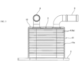
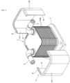
- FIG. 3 to FIG. 5 illustrate a first screen 11.
- This screen 11 is configured by bending a stainless steel thin plate (for example, a thickness of approximately 1 mm) such as, for example, SUS304 which is heat resistant, and the screen 11 is formed as a tube having a substantially square cross section and enclosing the core portion 3 of the heat exchanger 1.
- the inner wall face 11a forms a shape along the border of the core plates 4, the corners of which are rounded, such that there is a specific minute gap spanning the entire perimeter between the inner wall face 11a and the tip edges of the taper portion 4a of the core plates 4.
- the brim portion 12 curved toward the inner side of the perimeter is provided on the top end of the tube portion such that the top end of the minute gap created between the inner wall face 11a and the core portion 3 is covered.
- the screen 11 may be formed from other metal materials. As mentioned above, it is desirable for the metal material to have a coefficient of thermal expansion of at least 11 ⁇ 10 -6 and a melting point of at least 650 °C.
- the screen 11 is configured to be separated into two components, a first half portion 11A and a second half portion 11B, so as to sandwich, from both sides, the core portion 3 above the base plate 2.
- the center of the two opposing side faces are the separated faces of the first half portion 11A and the second half portion 11B.
- This first half portion 11A and second half portion 11B are disposed such that each edge 13 and 14 on the separated faces are opposing each other.
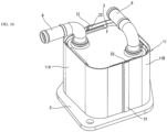
- FIG. 5 illustrates a state wherein only one half, the second half portion 11B, is mounted onto the base plate 2; however, as illustrated in FIG. 5 , the screen 11 is mounted onto the base plate 2 before the brazing process and conveyed together with the base plate 2. That is, it is sent into and out of the furnace while mounted onto the base plate 2.
- a workpiece fixed in an assembled state that is, a heat exchanger 1, using a jig (not illustrated), is heated and integrally brazed under inert gas inside a furnace while in a state of being enclosed by the screen 11. Moreover, the brazing process is completed and the temperature is sufficiently decreased, and thereafter, the screen 11 is taken off of the workpiece.
- the screen 11 can, obviously, be reused.
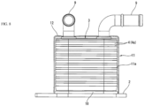
- FIG. 6 illustrates a second screen 11, wherein a plurality of locating pins 15 for locating the lowest core plate 4 in the core portion 3 is provided on the base plate 2 of the heat exchanger 1, which is the workpiece. That is, the lowest core plate 4 is set within an area enclosed by the plurality of locating pins 15. Moreover, the screen 11 is located above the base plate 2 using this plurality of locating pins 15. That is, the screen 11, which is separated in two, is set on the outer side of the plurality of locating pins 15. A swelled portion 16, which fits each locating pin 15, is formed on the bottom edge portion of the screen 11.
- the screen 11 is located above the base plate 2 using the locating pins 15, whereby managing the position of the screen 11 with respect to the core portion 3 becomes simple, and as a result brazing can be performed reliably.
- the screen 11 may be located by forming a groove in the base plate 2 as an engaging portion instead of the locating pins 15, the groove being formed along the shape of the outer circumference of the bottom end portion of the screen 11, and causing the bottom end of the screen 11 to engage with this groove.
- FIG. 7 illustrates a third screen 11, wherein the brim portion 12 is formed not in a shape following a simple flat face, but in a shape in which the inner perimeter end of the brim portion 12 is curved downward.
- the brim portion 12 has a convex cross sectional shape facing upwards.
- FIG. 8 illustrates a fourth screen 11, wherein a second base plate 18 smaller than the base plate 2 is superimposed on the base plate 2, and the screen 11 is located using the periphery of this second base plate 18. That is, the outer shape of the second base plate 18 corresponds to the desired position of the screen 11 and to the border of the inner wall face 11a of the screen 11 in this position, and the position of the screen 11 on the base plate 2 is controlled by fitting the screen 11 over the periphery of the second base plate 18.
- FIG. 9 and FIG. 10 illustrate a fifth screen 11 wherein the configuration of the boundary between the first half portion 11A and the second half portion 11B is modified.
- the edge portion 21 of the first half portion 11A extends, being offset to the outside only by the plate thickness, and overlaps together with the edge portion 22 of the second half portion 11B positioned on the inside. Accordingly, the generation of an interstice between the first half portion 11A and the second half portion 11B (that is, a channel out of which vaporized Mg and the like would flow) is inhibited, while the inner wall face 11a is a continuous face substantially without unevenness. That is, while each edge portion 21 and 22 are superimposed upon one another, a fixed minute gap along the entire perimeter between the core portion 3 can be obtained.
- brim portion 12 is not illustrated in FIG. 9 and FIG. 10 , but a brim portion 12 similar to that of the first example or the third example may be provided.
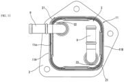
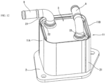
- FIG. 11 and FIG. 12 illustrate a sixth screen 11 in which the position of the boundary in the fifth example is modified.
- the boundaries between the first half portion 11A and the second half portion 11B are positioned at the mutually opposing corner portions of the substantially square-shaped tube portion.
- the edge portion 21 of the first half portion 11A extends, being offset to the outside only by the plate thickness, and overlaps together with the edge portion 22 of the second half portion 11B positioned on the inside.
- the generation of an interstice between the first half portion 11A and the second half portion 11B is inhibited, and the inner wall face 11a is a continuous face substantially without unevenness. That is, while each edge portion 21 and 22 are superimposed upon one another, a fixed minute gap along the entire perimeter between the core portion 3 can be obtained.
- brim portion 12 is not illustrated in FIG. 11 and FIG. 12 , but a brim portion 12 similar to that of the first example or the third example may be provided.
- the screen 11 is not limited to a configuration having two separations as described above, but may be configured to be separated into an arbitrary quantity such as three separations or four separations.
Landscapes
- Engineering & Computer Science (AREA)
- Mechanical Engineering (AREA)
- Physics & Mathematics (AREA)
- Thermal Sciences (AREA)
- General Engineering & Computer Science (AREA)
- Heat-Exchange Devices With Radiators And Conduit Assemblies (AREA)
Claims (8)
- Schirm (11) zur Verwendung beim Löten eines Wärmetauschers (1) mit einer Vielzahl von Kernplatten (4), die aus einem Mg-haltigen Lötblech aus Aluminiumlegierung gebildet sind und in einer Form gebildet sind, die einen Kegelabschnitt (4a) am Umfang aufweist, die erhitzt und unter einer Inertgasatmosphäre zusammen mit einer Grundplatte (2) auf der Unterseite, die größer und dicker als die Kernplatten (4) ist, gelötet werden, wobei:der Schirm (11) aus Metall als ein Rohr gebildet ist, das einen gestapelten Körper (3) der Kernplatten (4) umschließt, dem äußeren Rand der Kernplatten (4) derart folgt, dass die Innenwandfläche des Rohres einen bestimmten winzigen Spalt (D) zwischen sich und der Spitzenkante des Kegelabschnitts (4a) aufweist, und auf der Grundplatte (2) montiert ist, wobeider Kegelabschnitt (4a) derart gestapelt ist, dass die Kegelabschnitte (4a) einander berühren,dadurch gekennzeichnet, dass:da der Schirm (11) in eine Vielzahl von Teilen getrennt konfiguriert ist, um den gestapelten Körper (3) aus Kernplatten (4), die auf der Grundplatte (2) zusammengefügt sind, vom Umfang her zu umschließen, wobeider Schirm (11) zweigeteilt in einen ersten Halbabschnitt (11A) und einen zweiten Halbabschnitt (11B) konfiguriert ist, um den gestapelten Körper (3) aus Kernplatten (4), die auf der Grundplatte (2) zusammengefügt sind, von beiden Seiten her zu umschließen,wobei sich an der Grenze zwischen dem ersten Halbabschnitt (11A) und dem zweiten Halbabschnitt (11B) der Kantenabschnitt des einen nur um die Plattendicke nach außen versetzt erstreckt und zusammen mit dem anderen Kantenabschnitt, der an der Innenseite positioniert ist, überlappt,wobei der Schirm (11) gewölbte Abschnitte (16) umfasst, die am unteren Kantenabschnitt des Schirms (11) dazu gebildet sind, dass der Schirm (11) unter Verwendung von Positionierstiften (15) lokalisiert werden kann, die an einer Grundplatte (2) bereitgestellt sind, die in diese gewölbten Abschnitte (16) gepasst werden können, um den gestapelten Körper aus Kernplatten (4) auf der Grundplatte (2) zu lokalisieren.
- Schirm (11) zur Verwendung beim Löten eines Wärmetauschers (1) nach Anspruch 1 in Kombination mit einer Vielzahl von Kernplatten (4), die aus einem Mg-haltigen Lötblech aus Aluminiumlegierung gebildet sind, wobei die Kernplatten (4), die aus dem Lötblech gebildet sind, einen Kegelabschnitt (4a) aufweisen, der am Umfang schräg nach oben steht, und wenn jede Kernplatte (4) in einer vertikalen Richtung gestapelt ist, sich alle Kegelabschnitte (4a) gegenseitig überlappen und dicht aneinander liegen.
- Schirm (11) zur Verwendung beim Löten eines Wärmetauschers (1) nach Anspruch 1 oder 2, wobei eine zweite Grundplatte (18), die kleiner als die erste Grundplatte (2) ist, auf der Grundplatte (2) überlagert ist, und
der Schirm (11) unter Verwendung des Umfangs der zweiten Grundplatte (18) lokalisiert ist. - Schirm (11) zur Verwendung beim Löten eines Wärmetauschers (1) nach Anspruch 2, wobei der winzige Spalt (D) mindestens 0,5 mm und nicht mehr als 5 mm beträgt.
- Schirm (11) zur Verwendung beim Löten eines Wärmetauschers (1) nach einem der Ansprüche 1 bis 4, wobei ein Randabschnitt (12) zum Abdecken eines oberen Endes des winzigen Spalts (D) an einem oberen Ende des Rohrabschnitts, der den gestapelten Körper (3) aus Kernplatten (4) umschließt, bereitgestellt ist.
- Schirm (11) zur Verwendung beim Löten eines Wärmetauschers (1) nach einem der Ansprüche 1 bis 5, der sich aus einem metallischen Material zusammensetzt, das einen Wärmeausdehnungskoeffizienten von mindestens 11x10-6 und einen Schmelzpunkt von mindestens 650 °C aufweist.
- Schirm (11) zur Verwendung beim Löten eines Wärmetauschers (1) nach einem der Ansprüche 1 bis 6, wobei der Schirm (11) aus einem dünnen Metallblech aus rostfreiem Stahl oder einem anderen hitzebeständigen Metall besteht, das gerade hitzebeständig genug ist, um in der Lage zu sein, der Heiztemperatur beim Löten standzuhalten, und als ein Rohr gebildet ist, das einen im Wesentlichen vierseitigen Querschnitt aufweist, und den Kernabschnitt 3 umschließt.
- Lötverfahren für einen Wärmetauscher (1), umfassend: Stapeln einer Vielzahl von Kernplatten (4) - die aus einem Mg-haltigen Lötblech aus Aluminiumlegierung gebildet sind und in einer Form gebildet sind, die einen Kegelabschnitt (4a) am Umfang aufweist - auf einer Grundplatte (2) auf der Unterseite, die eine größere Dicke als die Kernplatten (4) aufweist, die derart gestapelt sind, dass die Kegelabschnitte (4a) einander berühren;
wobei das Verfahren durch Folgendes gekennzeichnet ist:Umschließen eines gestapelten Körpers (3) aus den Kernplatten (4) durch Montieren des Schirms (11) nach einem der Ansprüche 1 bis 7 auf der Grundplatte (2) derart, dass er zusammen mit der Grundplatte (2) förderbar ist; undLöten durch Einbringen der Grundplatte (2), an welcher der Schirm (11) noch montiert ist, zusammen mit dem gestapelten Körper (3) aus Kernplatten (4) in einen Ofen und Erhitzen unter einer Inertgasatmosphäre.
Applications Claiming Priority (2)
| Application Number | Priority Date | Filing Date | Title |
|---|---|---|---|
| JP2020019365A JP7431599B2 (ja) | 2020-02-07 | 2020-02-07 | 熱交換器のろう付け方法 |
| PCT/EP2021/051559 WO2021156084A1 (en) | 2020-02-07 | 2021-01-25 | Screen to be used during brazing of heat exchanger and brazing method for heat exchanger |
Publications (2)
| Publication Number | Publication Date |
|---|---|
| EP4100193A1 EP4100193A1 (de) | 2022-12-14 |
| EP4100193B1 true EP4100193B1 (de) | 2025-03-05 |
Family
ID=74236215
Family Applications (1)
| Application Number | Title | Priority Date | Filing Date |
|---|---|---|---|
| EP21701790.4A Active EP4100193B1 (de) | 2020-02-07 | 2021-01-25 | Sieb zur verwendung beim löten von wärmetauschern und lötverfahren für wärmetauscher |
Country Status (6)
| Country | Link |
|---|---|
| US (1) | US12472573B2 (de) |
| EP (1) | EP4100193B1 (de) |
| JP (1) | JP7431599B2 (de) |
| CN (1) | CN115052703A (de) |
| PL (1) | PL4100193T3 (de) |
| WO (1) | WO2021156084A1 (de) |
Families Citing this family (6)
| Publication number | Priority date | Publication date | Assignee | Title |
|---|---|---|---|---|
| JP7282468B2 (ja) * | 2019-10-04 | 2023-05-29 | Maアルミニウム株式会社 | アルミニウムブレージングシートおよびアルミニウム部材のフラックスフリーろう付方法 |
| JP2021122850A (ja) * | 2020-02-07 | 2021-08-30 | 株式会社マーレ フィルターシステムズ | ブレージングシート、ろう付け方法及び熱交換器の製造方法 |
| JP7431599B2 (ja) | 2020-02-07 | 2024-02-15 | マーレジャパン株式会社 | 熱交換器のろう付け方法 |
| CN115265242A (zh) * | 2022-09-26 | 2022-11-01 | 杭州沈氏节能科技股份有限公司 | 一种换热器及制造方法 |
| WO2024110123A1 (en) * | 2022-11-22 | 2024-05-30 | Mahle International Gmbh | Oil cooler |
| CN116638167A (zh) * | 2023-03-20 | 2023-08-25 | 南京百灵汽车电气机械有限公司 | 一种提高换热器钎焊合格率的方法 |
Citations (4)
| Publication number | Priority date | Publication date | Assignee | Title |
|---|---|---|---|---|
| AT184031B (de) * | 1951-09-26 | 1955-12-10 | Aluminium Ind Ag | Verfahren zur randseitigen Verbindung von flächenhaften Leichtmetallteilen durch Schmelzschweißung |
| JPS62296969A (ja) * | 1986-06-16 | 1987-12-24 | Seiwa Kogyosho:Kk | 電気温水器等の缶体の製造方法 |
| CN206158226U (zh) * | 2016-11-16 | 2017-05-10 | 沈阳建筑大学 | 钢管注浆快速加固柱结构 |
| CN208763003U (zh) * | 2018-08-02 | 2019-04-19 | 中交第四公路工程局有限公司 | 一种用于水中桩基施工的可拆卸钢护筒 |
Family Cites Families (44)
| Publication number | Priority date | Publication date | Assignee | Title |
|---|---|---|---|---|
| US2817895A (en) | 1956-08-16 | 1957-12-31 | Horizons Inc | Soldering flux composition and method of soldering with same |
| US3321828A (en) | 1962-01-02 | 1967-05-30 | Gen Electric | Aluminum brazing |
| US3941293A (en) * | 1969-09-22 | 1976-03-02 | Societe Anonyme Des Usines Chausson | Brazing jig for aluminum radiator cores |
| US4701127A (en) | 1982-12-10 | 1987-10-20 | Borg-Warner Corporation | Controlled atmosphere capsule for fluxless brazing |
| JPH0660727U (ja) * | 1993-01-25 | 1994-08-23 | カルソニック株式会社 | 触媒コンバータ |
| US5340015A (en) | 1993-03-22 | 1994-08-23 | Westinghouse Electric Corp. | Method for applying brazing filler metals |
| JPH0985433A (ja) | 1995-09-19 | 1997-03-31 | Sky Alum Co Ltd | フラックスレス非酸化性雰囲気ろう付け方法 |
| DE19722074A1 (de) * | 1997-05-27 | 1998-12-03 | Knecht Filterwerke Gmbh | Plattenwärmetauscher, insbesondere Öl/Kühlmittel-Kühler für Kraftfahrzeuge |
| US6031751A (en) | 1998-01-20 | 2000-02-29 | Reliance Electric Industrial Company | Small volume heat sink/electronic assembly |
| SE513784C2 (sv) * | 1999-03-09 | 2000-11-06 | Alfa Laval Ab | Permanent sammanfogad plattvärmeväxlare |
| JP2002168591A (ja) * | 2000-11-29 | 2002-06-14 | Denso Corp | アルミニウム製熱交換器 |
| US6904961B2 (en) * | 2003-01-07 | 2005-06-14 | Honeywell International, Inc. | Prime surface gas cooler for high temperature and method for manufacture |
| JP4342396B2 (ja) * | 2004-07-22 | 2009-10-14 | 古河スカイ株式会社 | ろう付け方法 |
| JP4474228B2 (ja) * | 2004-08-05 | 2010-06-02 | 株式会社デンソー | ろう付け方法 |
| JP4634789B2 (ja) | 2004-12-24 | 2011-02-16 | 古河スカイ株式会社 | ロウ付け方法 |
| US20070006998A1 (en) * | 2005-07-07 | 2007-01-11 | Viktor Brost | Heat exchanger with plate projections |
| US7942020B2 (en) * | 2007-07-27 | 2011-05-17 | Johnson Controls Technology Company | Multi-slab multichannel heat exchanger |
| JP2009036468A (ja) | 2007-08-02 | 2009-02-19 | Denso Corp | ハウジングレス式熱交換器 |
| JP2011007411A (ja) | 2009-06-25 | 2011-01-13 | Mahle Filter Systems Japan Corp | オイルクーラ |
| JP5298100B2 (ja) * | 2010-11-15 | 2013-09-25 | トヨタ自動車株式会社 | 車両用熱交換器 |
| JP5838048B2 (ja) | 2011-06-24 | 2015-12-24 | 株式会社マーレ フィルターシステムズ | オイルクーラ |
| JP5339556B2 (ja) | 2012-01-13 | 2013-11-13 | 古河スカイ株式会社 | 無フラックスろう付け用ブレージングシート及びその製造方法 |
| HUE053338T2 (hu) | 2012-05-04 | 2021-06-28 | Hydro Aluminium Rolled Prod | Alumínium bevont lemez alkalmazása fluxus nélküli forrasztáshoz |
| JP5844212B2 (ja) | 2012-05-07 | 2016-01-13 | 株式会社Uacj | アルミニウム合金ブレージングシート |
| JP6154122B2 (ja) | 2012-12-12 | 2017-06-28 | 株式会社マーレ フィルターシステムズ | 多板積層式熱交換器 |
| US8707747B1 (en) | 2012-12-14 | 2014-04-29 | Rohr, Inc. | Forming a shaped sandwich panel with a die and a pressure vessel |
| JP6184176B2 (ja) | 2013-06-06 | 2017-08-23 | 大陽日酸株式会社 | アルミニウム材のろう付け炉及びろう付け方法 |
| JP6132347B2 (ja) | 2013-07-31 | 2017-05-24 | 株式会社Uacj | アルミニウム合金ブレージングシートおよびその製造方法 |
| JP6376836B2 (ja) * | 2013-08-22 | 2018-08-22 | 株式会社マーレ フィルターシステムズ | 熱交換器 |
| SI3062949T2 (sl) * | 2013-10-29 | 2023-08-31 | Swep International Ab | Postopek trdega lotanja ploščatega izmenjevalnika toplote s pomočjo s sitotiskom nanešenega lota |
| JP6431789B2 (ja) | 2015-03-10 | 2018-11-28 | 株式会社Uacj | 中空構造体のろう付方法 |
| JP2016203193A (ja) | 2015-04-17 | 2016-12-08 | 株式会社Uacj | アルミニウム合金シート及びその製造方法、ならびに、当該アルミニウム合金シートを用いたアルミニウムブレージングシート |
| JP6363555B2 (ja) * | 2015-04-28 | 2018-07-25 | 株式会社デンソー | アルミニウム製熱交換器 |
| JP6468983B2 (ja) | 2015-10-16 | 2019-02-13 | 株式会社Uacj | アルミニウム合金ブレージングシート、その製造方法、アルミニウム合金シート及び熱交換器 |
| JP6463262B2 (ja) | 2015-12-28 | 2019-01-30 | 株式会社Uacj | アルミニウム合金ブレージングシート及びアルミニウム合金製熱交換器の製造方法 |
| JP6796929B2 (ja) | 2016-02-02 | 2020-12-09 | 株式会社カンドリ工業 | アルミニウム材のフラックスレスろう付け方法及びろう付け用処理装置 |
| JP6055573B1 (ja) | 2016-06-23 | 2016-12-27 | 三菱アルミニウム株式会社 | フラックスフリーろう付用のブレージングシート、フラックスフリーろう付方法および熱交換器のフラックスフリーろう付方法 |
| JP6487974B2 (ja) | 2017-08-17 | 2019-03-20 | 株式会社Uacj | 熱交換器用アルミニウム合金ブレージングシート及び熱交換器用アルミニウム合金ブレージングシートの製造方法 |
| FR3074717B1 (fr) | 2017-12-12 | 2019-11-08 | Constellium Neuf-Brisach | Tole de brasage multicouche en aluminium pour brasage sans flux |
| EP3747582B1 (de) | 2018-02-02 | 2024-04-17 | UACJ Corporation | Lötverfahren |
| JP6844569B2 (ja) | 2018-03-27 | 2021-03-17 | 住友電装株式会社 | ワイヤハーネス用経路規制部材及びワイヤハーネス |
| CN112955281B (zh) | 2018-10-26 | 2022-12-27 | 株式会社Uacj | 铝合金硬钎焊板及其制造方法 |
| FR3088996B1 (fr) * | 2018-11-26 | 2020-12-25 | Air Liquide | Procédé de fabrication d’un échangeur comprenant une zone à supporter et échangeur fabriqué par un tel procédé |
| JP7431599B2 (ja) | 2020-02-07 | 2024-02-15 | マーレジャパン株式会社 | 熱交換器のろう付け方法 |
-
2020
- 2020-02-07 JP JP2020019365A patent/JP7431599B2/ja active Active
-
2021
- 2021-01-25 CN CN202180012705.3A patent/CN115052703A/zh active Pending
- 2021-01-25 EP EP21701790.4A patent/EP4100193B1/de active Active
- 2021-01-25 WO PCT/EP2021/051559 patent/WO2021156084A1/en not_active Ceased
- 2021-01-25 US US17/798,066 patent/US12472573B2/en active Active
- 2021-01-25 PL PL21701790.4T patent/PL4100193T3/pl unknown
Patent Citations (4)
| Publication number | Priority date | Publication date | Assignee | Title |
|---|---|---|---|---|
| AT184031B (de) * | 1951-09-26 | 1955-12-10 | Aluminium Ind Ag | Verfahren zur randseitigen Verbindung von flächenhaften Leichtmetallteilen durch Schmelzschweißung |
| JPS62296969A (ja) * | 1986-06-16 | 1987-12-24 | Seiwa Kogyosho:Kk | 電気温水器等の缶体の製造方法 |
| CN206158226U (zh) * | 2016-11-16 | 2017-05-10 | 沈阳建筑大学 | 钢管注浆快速加固柱结构 |
| CN208763003U (zh) * | 2018-08-02 | 2019-04-19 | 中交第四公路工程局有限公司 | 一种用于水中桩基施工的可拆卸钢护筒 |
Also Published As
| Publication number | Publication date |
|---|---|
| US12472573B2 (en) | 2025-11-18 |
| PL4100193T3 (pl) | 2025-08-11 |
| EP4100193A1 (de) | 2022-12-14 |
| JP2021122849A (ja) | 2021-08-30 |
| JP7431599B2 (ja) | 2024-02-15 |
| WO2021156084A1 (en) | 2021-08-12 |
| CN115052703A (zh) | 2022-09-13 |
| US20230089422A1 (en) | 2023-03-23 |
Similar Documents
| Publication | Publication Date | Title |
|---|---|---|
| EP4100193B1 (de) | Sieb zur verwendung beim löten von wärmetauschern und lötverfahren für wärmetauscher | |
| EP4100202B1 (de) | Hartlötblech, lötverfahren und verfahren zur herstellung eines wärmetauschers | |
| EP3062949B1 (de) | Verfahren zum löten eines plattenwärmetauschers anhand eines mittels siebdruck hergestellten lötmaterials | |
| CA2676301C (en) | Plate heat exchanger | |
| US20100108042A1 (en) | Heat exchanger, method of manufacturing the same, and egr system | |
| US8029918B2 (en) | Brazing method and brazed structure | |
| US20120138280A1 (en) | Layer heat exchanger for high temperatures | |
| JP7553866B2 (ja) | 冷却構造、バッテリーユニット、及び冷却構造の製造方法 | |
| CN107167000A (zh) | 板式热交换器和制造板式热交换器的方法 | |
| CN105324626B (zh) | 具有双功能分配头连接组合体的热交换器 | |
| JP4243654B2 (ja) | 電子機器部品の液体冷却板、液体冷却板の製造方法 | |
| JP2009007649A (ja) | マスク用フレーム | |
| US6453990B2 (en) | Layered heat exchanger | |
| EP1400300A1 (de) | Laminierte wärmebeständige legierungsplatte und verfahren zur herstellung derselben | |
| US11333442B2 (en) | Brazeable metal sheet material, and heat exchanger with components made of the same | |
| CN112577336B (zh) | 用于换热器的翅片和换热器 | |
| US12496648B2 (en) | Furnace braze cycle enhancement | |
| JP2006265678A (ja) | リン銅ろうクラッド材及びその製造方法並びにリン銅ろうクラッド材のろう付け方法 | |
| EP3907036A1 (de) | Mehrschichtiges aluminiumlötblechmaterial | |
| JP2012132627A (ja) | プレート式熱交換器 | |
| JP2005214521A (ja) | 積層型熱交換器 |
Legal Events
| Date | Code | Title | Description |
|---|---|---|---|
| STAA | Information on the status of an ep patent application or granted ep patent |
Free format text: STATUS: UNKNOWN |
|
| STAA | Information on the status of an ep patent application or granted ep patent |
Free format text: STATUS: THE INTERNATIONAL PUBLICATION HAS BEEN MADE |
|
| PUAI | Public reference made under article 153(3) epc to a published international application that has entered the european phase |
Free format text: ORIGINAL CODE: 0009012 |
|
| STAA | Information on the status of an ep patent application or granted ep patent |
Free format text: STATUS: REQUEST FOR EXAMINATION WAS MADE |
|
| 17P | Request for examination filed |
Effective date: 20220719 |
|
| AK | Designated contracting states |
Kind code of ref document: A1 Designated state(s): AL AT BE BG CH CY CZ DE DK EE ES FI FR GB GR HR HU IE IS IT LI LT LU LV MC MK MT NL NO PL PT RO RS SE SI SK SM TR |
|
| DAV | Request for validation of the european patent (deleted) | ||
| DAX | Request for extension of the european patent (deleted) | ||
| STAA | Information on the status of an ep patent application or granted ep patent |
Free format text: STATUS: EXAMINATION IS IN PROGRESS |
|
| 17Q | First examination report despatched |
Effective date: 20231026 |
|
| GRAP | Despatch of communication of intention to grant a patent |
Free format text: ORIGINAL CODE: EPIDOSNIGR1 |
|
| STAA | Information on the status of an ep patent application or granted ep patent |
Free format text: STATUS: GRANT OF PATENT IS INTENDED |
|
| INTG | Intention to grant announced |
Effective date: 20241025 |
|
| GRAS | Grant fee paid |
Free format text: ORIGINAL CODE: EPIDOSNIGR3 |
|
| GRAA | (expected) grant |
Free format text: ORIGINAL CODE: 0009210 |
|
| STAA | Information on the status of an ep patent application or granted ep patent |
Free format text: STATUS: THE PATENT HAS BEEN GRANTED |
|
| AK | Designated contracting states |
Kind code of ref document: B1 Designated state(s): AL AT BE BG CH CY CZ DE DK EE ES FI FR GB GR HR HU IE IS IT LI LT LU LV MC MK MT NL NO PL PT RO RS SE SI SK SM TR |
|
| REG | Reference to a national code |
Ref country code: GB Ref legal event code: FG4D |
|
| REG | Reference to a national code |
Ref country code: CH Ref legal event code: EP |
|
| REG | Reference to a national code |
Ref country code: DE Ref legal event code: R096 Ref document number: 602021027115 Country of ref document: DE |
|
| REG | Reference to a national code |
Ref country code: IE Ref legal event code: FG4D |
|
| PG25 | Lapsed in a contracting state [announced via postgrant information from national office to epo] |
Ref country code: RS Free format text: LAPSE BECAUSE OF FAILURE TO SUBMIT A TRANSLATION OF THE DESCRIPTION OR TO PAY THE FEE WITHIN THE PRESCRIBED TIME-LIMIT Effective date: 20250605 |
|
| PG25 | Lapsed in a contracting state [announced via postgrant information from national office to epo] |
Ref country code: FI Free format text: LAPSE BECAUSE OF FAILURE TO SUBMIT A TRANSLATION OF THE DESCRIPTION OR TO PAY THE FEE WITHIN THE PRESCRIBED TIME-LIMIT Effective date: 20250305 |
|
| REG | Reference to a national code |
Ref country code: NL Ref legal event code: MP Effective date: 20250305 |
|
| PG25 | Lapsed in a contracting state [announced via postgrant information from national office to epo] |
Ref country code: ES Free format text: LAPSE BECAUSE OF FAILURE TO SUBMIT A TRANSLATION OF THE DESCRIPTION OR TO PAY THE FEE WITHIN THE PRESCRIBED TIME-LIMIT Effective date: 20250305 |
|
| REG | Reference to a national code |
Ref country code: LT Ref legal event code: MG9D |
|
| PG25 | Lapsed in a contracting state [announced via postgrant information from national office to epo] |
Ref country code: NO Free format text: LAPSE BECAUSE OF FAILURE TO SUBMIT A TRANSLATION OF THE DESCRIPTION OR TO PAY THE FEE WITHIN THE PRESCRIBED TIME-LIMIT Effective date: 20250605 |
|
| PG25 | Lapsed in a contracting state [announced via postgrant information from national office to epo] |
Ref country code: HR Free format text: LAPSE BECAUSE OF FAILURE TO SUBMIT A TRANSLATION OF THE DESCRIPTION OR TO PAY THE FEE WITHIN THE PRESCRIBED TIME-LIMIT Effective date: 20250305 |
|
| PG25 | Lapsed in a contracting state [announced via postgrant information from national office to epo] |
Ref country code: LV Free format text: LAPSE BECAUSE OF FAILURE TO SUBMIT A TRANSLATION OF THE DESCRIPTION OR TO PAY THE FEE WITHIN THE PRESCRIBED TIME-LIMIT Effective date: 20250305 |
|
| PG25 | Lapsed in a contracting state [announced via postgrant information from national office to epo] |
Ref country code: GR Free format text: LAPSE BECAUSE OF FAILURE TO SUBMIT A TRANSLATION OF THE DESCRIPTION OR TO PAY THE FEE WITHIN THE PRESCRIBED TIME-LIMIT Effective date: 20250606 Ref country code: BG Free format text: LAPSE BECAUSE OF FAILURE TO SUBMIT A TRANSLATION OF THE DESCRIPTION OR TO PAY THE FEE WITHIN THE PRESCRIBED TIME-LIMIT Effective date: 20250305 |
|
| REG | Reference to a national code |
Ref country code: AT Ref legal event code: MK05 Ref document number: 1772490 Country of ref document: AT Kind code of ref document: T Effective date: 20250305 |
|
| PG25 | Lapsed in a contracting state [announced via postgrant information from national office to epo] |
Ref country code: NL Free format text: LAPSE BECAUSE OF FAILURE TO SUBMIT A TRANSLATION OF THE DESCRIPTION OR TO PAY THE FEE WITHIN THE PRESCRIBED TIME-LIMIT Effective date: 20250305 |
|
| PG25 | Lapsed in a contracting state [announced via postgrant information from national office to epo] |
Ref country code: SE Free format text: LAPSE BECAUSE OF FAILURE TO SUBMIT A TRANSLATION OF THE DESCRIPTION OR TO PAY THE FEE WITHIN THE PRESCRIBED TIME-LIMIT Effective date: 20250305 |
|
| PG25 | Lapsed in a contracting state [announced via postgrant information from national office to epo] |
Ref country code: SM Free format text: LAPSE BECAUSE OF FAILURE TO SUBMIT A TRANSLATION OF THE DESCRIPTION OR TO PAY THE FEE WITHIN THE PRESCRIBED TIME-LIMIT Effective date: 20250305 |
|
| PG25 | Lapsed in a contracting state [announced via postgrant information from national office to epo] |
Ref country code: PT Free format text: LAPSE BECAUSE OF FAILURE TO SUBMIT A TRANSLATION OF THE DESCRIPTION OR TO PAY THE FEE WITHIN THE PRESCRIBED TIME-LIMIT Effective date: 20250707 |
|
| PG25 | Lapsed in a contracting state [announced via postgrant information from national office to epo] |
Ref country code: AT Free format text: LAPSE BECAUSE OF FAILURE TO SUBMIT A TRANSLATION OF THE DESCRIPTION OR TO PAY THE FEE WITHIN THE PRESCRIBED TIME-LIMIT Effective date: 20250305 |
|
| PG25 | Lapsed in a contracting state [announced via postgrant information from national office to epo] |
Ref country code: CZ Free format text: LAPSE BECAUSE OF FAILURE TO SUBMIT A TRANSLATION OF THE DESCRIPTION OR TO PAY THE FEE WITHIN THE PRESCRIBED TIME-LIMIT Effective date: 20250305 Ref country code: EE Free format text: LAPSE BECAUSE OF FAILURE TO SUBMIT A TRANSLATION OF THE DESCRIPTION OR TO PAY THE FEE WITHIN THE PRESCRIBED TIME-LIMIT Effective date: 20250305 |
|
| PG25 | Lapsed in a contracting state [announced via postgrant information from national office to epo] |
Ref country code: RO Free format text: LAPSE BECAUSE OF FAILURE TO SUBMIT A TRANSLATION OF THE DESCRIPTION OR TO PAY THE FEE WITHIN THE PRESCRIBED TIME-LIMIT Effective date: 20250305 |
|
| PG25 | Lapsed in a contracting state [announced via postgrant information from national office to epo] |
Ref country code: SK Free format text: LAPSE BECAUSE OF FAILURE TO SUBMIT A TRANSLATION OF THE DESCRIPTION OR TO PAY THE FEE WITHIN THE PRESCRIBED TIME-LIMIT Effective date: 20250305 |
|
| PG25 | Lapsed in a contracting state [announced via postgrant information from national office to epo] |
Ref country code: IS Free format text: LAPSE BECAUSE OF FAILURE TO SUBMIT A TRANSLATION OF THE DESCRIPTION OR TO PAY THE FEE WITHIN THE PRESCRIBED TIME-LIMIT Effective date: 20250705 |
|
| P01 | Opt-out of the competence of the unified patent court (upc) registered |
Free format text: CASE NUMBER: UPC_APP_8059_4100193/2025 Effective date: 20250926 |
|
| REG | Reference to a national code |
Ref country code: DE Ref legal event code: R097 Ref document number: 602021027115 Country of ref document: DE |
|
| PLBE | No opposition filed within time limit |
Free format text: ORIGINAL CODE: 0009261 |
|
| STAA | Information on the status of an ep patent application or granted ep patent |
Free format text: STATUS: NO OPPOSITION FILED WITHIN TIME LIMIT |
|
| PG25 | Lapsed in a contracting state [announced via postgrant information from national office to epo] |
Ref country code: DK Free format text: LAPSE BECAUSE OF FAILURE TO SUBMIT A TRANSLATION OF THE DESCRIPTION OR TO PAY THE FEE WITHIN THE PRESCRIBED TIME-LIMIT Effective date: 20250305 |
|
| REG | Reference to a national code |
Ref country code: CH Ref legal event code: L10 Free format text: ST27 STATUS EVENT CODE: U-0-0-L10-L00 (AS PROVIDED BY THE NATIONAL OFFICE) Effective date: 20260114 |