EP4100179B1 - Schweissmaschine - Google Patents
Schweissmaschine Download PDFInfo
- Publication number
- EP4100179B1 EP4100179B1 EP21708070.4A EP21708070A EP4100179B1 EP 4100179 B1 EP4100179 B1 EP 4100179B1 EP 21708070 A EP21708070 A EP 21708070A EP 4100179 B1 EP4100179 B1 EP 4100179B1
- Authority
- EP
- European Patent Office
- Prior art keywords
- carriage
- welding machine
- machine according
- hole
- clamping means
- Prior art date
- Legal status (The legal status is an assumption and is not a legal conclusion. Google has not performed a legal analysis and makes no representation as to the accuracy of the status listed.)
- Active
Links
Images


Classifications
-
- B—PERFORMING OPERATIONS; TRANSPORTING
- B23—MACHINE TOOLS; METAL-WORKING NOT OTHERWISE PROVIDED FOR
- B23K—SOLDERING OR UNSOLDERING; WELDING; CLADDING OR PLATING BY SOLDERING OR WELDING; CUTTING BY APPLYING HEAT LOCALLY, e.g. FLAME CUTTING; WORKING BY LASER BEAM
- B23K11/00—Resistance welding; Severing by resistance heating
- B23K11/04—Flash butt welding
- B23K11/046—Apparatus therefor
-
- B—PERFORMING OPERATIONS; TRANSPORTING
- B21—MECHANICAL METAL-WORKING WITHOUT ESSENTIALLY REMOVING MATERIAL; PUNCHING METAL
- B21B—ROLLING OF METAL
- B21B15/00—Arrangements for performing additional metal-working operations specially combined with or arranged in, or specially adapted for use in connection with, metal-rolling mills
- B21B15/0085—Joining ends of material to continuous strip, bar or sheet
Definitions
- the present invention relates to a welding machine, preferably of the flash welding type, for longitudinal metal products, e.g. billets, bars or blooms, adapted to weld the head and tail of two consecutive longitudinal products to each other along a roller pathway, usually arranged upstream of a rolling mill.
- EP3578276A1 discloses a welding machine according to the preamble of claim 1.
- the metal products from the casting machine or from external warehouses are welded together and then seamlessly rolled.
- the metal products, which are welded, are typically semifinished casting products, e.g. such as, billets, bars or blooms.
- the welding is carried out by joining the tail of one product to the head of the successive product.
- the welding is achieved by means of electric arcs produced by power supplies connected to the products to be welded. This technology is known as flash welding.
- clamping means serve to keep the products in place while welding and that often act also as conductors of the welding electric current.
- Such clamping means typically comprise elements, in particular clamps, which come directly into contact with the products to be welded. Gradually as the welding is carried out, the clamps, which hold the head and tail of the products to be welded, are brought close by means of hydraulic cylinders, named upsetting cylinders. This operation is necessary to join the ends to be welded, to eliminate any inclusions and air bubbles and to compensate for the loss of material, in the form of burrs, determined by the melting, and to allow the effective adhesion between the two components being welded, which form a joint, named weld joint.
- a known type of flash butt welding machine generally comprises two structures, each provided with a pair of clamps, the structures being substantially parallel to each other and inclined at an angle of about 45° relative to the plane defined by the carriage supporting the machine. Said inclination allows a uniform application of the contact force of the clamps with the product on the sides thereof, thus allowing its optimal retention and centering.
- the transformer provided with conductors connected to the two structures to supply electric current to the tail and head of the two products to be welded, is located above the inclined upper surfaces of the two structures, which makes access and, consequently, maintenance of the internal parts of the machine difficult. Even the disassembly and removal of heavy parts from the machine become difficult operations which must be carried out manually by the operators, who must enter inside the machine in difficult conditions.
- the present invention achieves at least one of such objects and other objects which will be apparent in light of the present description, by means of a welding machine, preferably of the flash butt welding type, to weld the tail of a first longitudinal metal product together with the head of a second longitudinal metal product along a feeding direction X of said longitudinal metal products, the machine comprising a carriage adapted to slide along the feeding direction X, said carriage supporting
- the transformer is integrally fixed to the carriage and, not being positioned above the two structures, access from above and, consequently, maintenance of the internal parts of the machine are facilitated. Disassembly and removal of heavy parts and components from the machine also become extremely simple operations, which can be carried out with common aids, such as cranes and overhead cranes.
- the machine components subject to maintenance are accessible and can be lifted from above.
- the conductors which connect the transformer to the first clamping means and the second clamping means, respectively pass underneath the first structure and the second structure, respectively, so that both the space between the first clamping means and the space between the second clamping means are freely accessible from below in the absence of longitudinal metal products to be welded.
- a further advantage is represented by the variant in which the second structure can slide, parallel to the feeding direction and relative to both the first structure and the carriage, on two beams, which are part of the carriage itself and which delimit said first part of the carriage, or can slide on two further beams, distinct from the beams of the carriage, which are part of a lifting system adapted to lift together both the first structure and the second structure with respect to the carriage by means of a rotation of a predetermined angle along a plane which is transverse to said feeding direction.
- the configuration of the welding machine according to the invention allows to make a drainage floor underneath it, which can be at a distance of less than 1.5 meters from the product passline, preferably less than 1 meter. This means lower costs for the realization of the foundations of the production line.
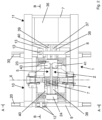
- the welding machine which is suitable for welding the tail of a first longitudinal metal product to the head of a second longitudinal metal product along a feeding direction X of said longitudinal metal products, comprises a carriage 1, adapted to slide on at least two sliding guides 20, 30 along said feeding direction X above a roller path (not shown) on which the longitudinal metal products, such as billets, blooms or bars, advance.
- the carriage 1 supports:
- the first structure 2 defines a longitudinal axis Z ( Figure 1 ), inclined relative to a horizontal plane, by an acute angle, preferably between 30° and 70°, e.g. 45°.
- the second structure 5, defining an own longitudinal axis Z' parallel to the longitudinal axis Z ( Figure 1 ), is arranged substantially parallel to the first structure 2 and spaced from the latter along the feeding direction X of the products to be welded.
- first structure 2 and the second structure 5 substantially parallel to each other, define a respective longitudinal axis arranged substantially horizontally.
- At least one infeed guide and at least one outfeed guide are optionally provided for the infeed and outfeed of metal products from the welding machine, each guide being constrained to a respective structure 2, 5 along the feeding axis X.
- said guides can be part of the carriage 1.
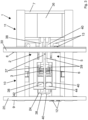
- both the first clamping means 3, 4 and the second clamping means 6, 7 are possibly adjustable in position by means of respective moving systems 41, 42; 43, 44 provided on the first structure 2 and on the second structure 5, respectively ( Figure 2 and 3 ).
- Such moving systems comprise, for example, hydraulic cylinders or jacks, or electric actuators or mechanical moving devices, such as cam or eccentric devices.
- first clamping means 3, 4 of the first structure 2 comprise a respective upper clamp 3 and a respective lower clamp 4.
- Each clamp 3, 4 can be moved along the Z-axis by a respective moving system 41, 42 ( Figures 2 and 3 ).
- the second clamping means 6, 7 of the second structure 5 comprise a respective upper clamp 6 and a respective lower clamp 7.
- each clamp 6, 7 can be possibly moved along the Z'-axis by a respective moving system 43, 44 ( Figures 2 and 3 ).
- the movement, and therefore the adjustability, of all the clamps of the clamping means advantageously eliminates the need to have to incline or rotate slightly the two structures 2, 5 to prevent the metal product, e.g. the billet, from slipping on the lower clamps, which are fixed in the machines of the prior art.
- the first structure 2 and the second structure 5 are supported, and possibly also contained, in a first part 10 of the carriage 1 delimited by a first beam 9 and a second beam 8 of the carriage that are parallel to each other and to the feeding direction X, while the at least one transformer 36 is fixed to the carriage 1 and supported, and possibly also contained, entirely in a second part 11 of the carriage 1, arranged laterally outside the first part 10.
- the transformer 36 can be a single transformer. Alternatively, a group of transformers can be provided which concur to electrically supply the clamps 3, 4, 6, 7 by means of the conductors 37, 38, 39, 40.
- the second part 11 of the carriage 1 can be delimited by said second beam 8 and a third beam 7 of the carriage 1, preferably parallel to the second beam 8.
- the first beam 9 and the third beam 7 are peripheral beams of the carriage 1 while the second beam 8 is an intermediate beam.
- At least two further peripheral beams, which are transverse, preferably perpendicular, to the beams 9, 8, 7 are provided to define the perimeter of the carriage 1 together with the beams 9 and 7.
- the carriage 1 is preferably arranged on two sliding guides 20, 30 fixed, either directly or by means of frames, on a floor below the welding machine, said sliding guides being parallel to each other and to the axis X.
- the first beam 9 and the second beam 8 of the carriage 1 are positioned at a respective sliding guide 20, 30.
- the first part 10 of the carriage 1 is above and at an area delimited by the sliding guides 20, 30.
- the second beam 8 is positioned at the sliding guide 30, while the third beam 7 is positioned at the sliding guide 20.
- the second part 11 of the carriage 1 is above and at the area delimited by the sliding guides 20, 30.
- the beams 9, 8 or the beams 8, 7 could also be offset relative to the sliding guides 20, 30.
- the conductors 37, 38 and 39, 40 connect the transformer 36 to the first clamping means 3, 4 and to the second clamping means 6, 7, respectively, passing underneath the first structure 2 and the second structure 5, respectively, in order to leave both the space between the first clamping means 3, 4 and the space between the second clamping means 6, 7 freely accessible from below in the absence of longitudinal metal products to be welded.
- the upper conductors 37, 39 exiting the transformer 36 can advance parallel to each other by passing for a small stretch respectively below the first structure 2 and the second structure 5 until arriving in proximity of the respective upper clamps 3 and 6.
- the pattern of the current is such that the circuit closes between the upper clamps 3 and 6 of the two structures.
- the lower conductors 38, 40 exiting from the transformer 36 can advance parallel to each other with a first stretch thereof below the first structure 2 and the second structure 5, respectively.
- the lower conductors 38, 40 can deviate by moving away from each other with a second stretch thereof and then advance parallel to each other again with a third stretch thereof, and approach each other again in proximity of the foot of the first structure 2 and of the second structure 5 with a fourth stretch thereof.
- a fifth and final stretch of the conductors 38, 40 finally arrives in proximity of the respective lower clamps 4 and 7.
- the pattern of the current is such that the circuit closes between the lower clamps 4 and 7 of the two structures.
- the configuration of the stretches of the lower conductors 38, 40 is thus designed to leave completely accessible from below at least the area comprising the clamping means 3, 4 and 6, 7.
- both the space between the first clamping means 3, 4 and the space between the second clamping means 6, 7 are freely accessible both from above and below in the absence of longitudinal metal products to be welded.
- the variant comprising two or more transformers in the second part 11 of the carriage 1, e.g. only two transformers arranged on top of each other, a first upper conductor and a first lower conductor exit the respective transformer and respectively reach the clamps 3, 4 of the first structure 2; while a second upper conductor and a second lower conductor exit the respective transformer and respectively reach the clamps 6, 7 of the second structure 5.
- the pattern of the currents is such that the two circuits close between the upper clamps 3 and 6 and between the lower clamps 4 and 7, respectively.
- the conductors can be arranged in configurations other than those described above, while maintaining free access from below to both the space between the first clamping means 3, 4 and the space between the second clamping means 6, 7, in the absence of the longitudinal metal products to be welded.
- the first structure 2 and the second structure 5, in addition to being arranged substantially parallel to each other, are arranged transversely, preferably orthogonally, to the first beam 9 and the second beam 8.
- the first beam 9 and the second beam 8 have a respective first portion, proximal to the first structure 2 and to which said first structure 2 is integrally fixed, and a respective second portion, distal from the first structure 2 and to which the second structure 5 is slidingly connected.
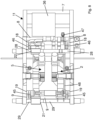
- the second portion of the first beam 9 is inserted in a first through-hole 21 of the second structure 5 ( Figures 1 and 5 ) internally provided with first rolls or pads 12 for a sliding of the second structure 5 on the first beam 9; and the second portion of the second beam 8 is inserted in a second through-hole 22 of the second structure 5 ( Figure 5 ) provided internally with second rolls or pads 13 for a sliding of the second structure 5 on the second beam 8.
- both the second portion of the first beam 9 and the first through-hole 21 have a quadrangular cross-section, and said first through-hole 21 is provided with first rolls or pads 12 only on two mutually opposite inner sides ( Figure 5 ), preferably above and below the first beam 9.
- a pair of first rolls 12 is provided on each of said two inner sides ( Figure 4 ).
- the second portion of the second beam 8 and the second through-hole 22 can have a quadrangular section, and said second through-hole 22 is provided with at least one second roll or pad 13 on at least three of its inner sides.
- four rolls or pads 13 are provided, one on each of the inner sides of the through-hole 22.
- first rolls 12 are idle, accommodated in respective seats obtained in the second structure 5 and protruding into the first through-hole 21 to come into contact with mutually opposite surfaces of the first beam 9; and also the second rolls 13 are idle, accommodated in respective seats obtained in the second structure 5 and protruding into the second through-hole 22 to come into contact with the respective side surface of the second beam 8.
- both the second portion of the first beam 9 and the first through-hole 21 have a round section, and said first through-hole 21 is provided with first pads 12; and both the second portion of the second beam 8 and the second through-hole 22 have a round section and said second through-hole 22 is provided with second pads 13.
- the sliding of the second structure 5 on the beams 9 and 8 can alternatively be achieved by reversing the configuration of the rolls or pads between the two through-holes 21, 22. Therefore, the first through-hole 21 of the second structure 5 can be internally provided with at least three rolls or pads 13 for a sliding of the second structure 5 on the first beam 9; and the second through-hole 22 of the second structure 5 can be internally provided with second rolls or pads 12, only on two internal sides opposite to each other, for a sliding of the second structure 5 on the second beam 8.
- a second variant shown in Figures 8 and 9 , provides that the first structure 2 and the second structure 5 are supported in the first part 10 of the carriage 1 not by means of the beams 8 and 9 of the carriage itself, but instead by means of a lifting system adapted to lifting said first structure 2 and said second structure 5 together with respect to the carriage 1, by means of a rotation along a plane which is transverse to the feeding direction X.
- a rotation can be in the range of 1° to 25°, e.g. 1° to 15°.
- Said lifting system preferably of the linkage type, comprises:
- the longitudinal axes of the first rotating shaft 19 and the second rotating shaft 18 are parallel and arranged on a first horizontal plane.
- the longitudinal axes of the further first beam 29 and the further second beam 28 are also parallel and arranged on a second horizontal plane, located above the first horizontal plane.
- the relative position between each rotating shaft 18, 19 and the corresponding further beam 28, 29 is such that the levers 45, 46 are always inclined at an acute angle other than zero with respect to the vertical.
- the further first beam 29 and the further second beam 28 support both the first structure 2 and the second structure 5, which are arranged substantially parallel to each other and transversely, preferably orthogonally, to said further first beam 29 and said further second beam 28.
- At least one actuator 47 is provided, adapted to rotate the first rotating shaft 19 and/or the second rotating shaft 18 by a predetermined angle so that the first structure 2 and the second structure 5 can be lifted together with respect to the carriage 1.
- only one actuator 47 is provided, e.g. fixed on the beam 8 of the carriage 1, which acts on a further lever 49 of the second rotating shaft 18.
- a connecting rod or tie rod 48 can synchronize the rotations of the two rotating shafts 18, 19, facilitating the lifting, by rotation, of the further beams 28, 29.
- the further first beam 29 and said further second beam 28 have a respective first portion, which is proximal to the first structure 2 and to which said first structure 2 is integrally fixed, and a respective second portion, which is distal from the first structure 2 and to which the second structure 5 is slidingly connected.
- the second portion of the further first beam 29 is inserted into a first through-hole 21 of the second structure 5, internally provided with first rolls or pads for a sliding of the second structure 5 on said further first beam 29; and the second portion of the further second beam 28 is inserted into a second through-hole 22 of the second structure 5, internally provided with second rolls or pads for a sliding of the second structure 5 on said further second beam 28.
- both the second portion of the further first beam 29 and the first through-hole 21 have a quadrangular cross-section, and said first through-hole 21 is provided with first rolls or pads only on two inner sides opposite to each other (in a manner similar to Figure 5 ), preferably above and below the beam 29.
- a pair of first rolls is provided on each of said two inner sides (in a manner similar to Figure 4 ).
- the second portion of the further second beam 28 and the second through-hole 22 can have a quadrangular section and said second through-hole 22 is provided with at least one second roll or pad on at least three of its inner sides.
- the first rolls are idle, accommodated in respective seats obtained in the second structure 5 and protruding into the first through-hole 21 to come into contact with mutually opposite surfaces of the further first beam 29; and also the second rolls are idle, accommodated in respective seats in the second structure 5 and protruding into the second through-hole 22 to come into contact with the respective side surface of the further second beam 28.
- both the second portion of the further first beam 29 and the first through-hole 21 have a round section, and said first through-hole 21 is provided with first pads; and both the second portion of the further second beam 28 and the second through-hole 22 have a round section and said second through-hole 22 is provided with second pads.
- the sliding of the second structure 5 on the further beams 29 and 28 can alternatively be achieved by reversing the configuration of the rolls or pads between the two through-holes 21, 22. Therefore, the first through-hole 21 of the second structure 5 can be internally provided with at least three second rolls or pads for a sliding of the second structure 5 on the further first beam 9; and the second through-hole 22 of the second structure 5 can be internally provided with first rolls or pads, only on two internal sides opposite to each other, for a sliding of the second structure 5 on the further second beam 28.
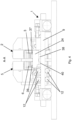
- a further advantage of the invention can be that of making the carriage 1 provided with at least one motor 31 connected to a toothed wheel 32 adapted to engage a rack 33 provided on at least one of the sliding guides 20, 30 ( Figure 6 ), preferably on one of the sides of the sliding guide.
- adjustment means 23, 24 can be provided for moving the second structure 5 towards or away from the first structure 2 along said feeding direction X.
- the approaching is made, in particular, when welding two products by flash welding.
- said adjustment means are upsetting cylinders 23, 24, which preferably are two in number.
- the upsetting cylinders 23, 24 are pivoted at a first end thereof to the first structure 2 and at a second end thereof to the second structure 5 by means of respective pins.
- a first upsetting cylinder 23 is arranged inferiorly behind both the first structure 2 and the second structure 5.
- the second upsetting cylinder 24 is arranged substantially at the feet of both the first structure 2 and the second structure 5.
- the two upsetting cylinders 23, 24 are arranged along a same substantially horizontal plane.
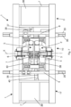
- FIG. 7 A second embodiment of the welding machine of the invention is shown in Figure 7 .
- the description provided above for the first embodiment also applies to this second embodiment.
- the latter differs from the first embodiment in that it provides for:
- the first part 10 of the carriage 1 is delimited by the first beam 9 and by the second beam 8 of the carriage 1, which are parallel to the feeding direction X.
- the second part 11 of the carriage 1 is delimited by said second beam 8 and by a third beam 7 of the carriage 1, preferably parallel to the second beam 8.
- the third part 11' of the carriage 1 is delimited by said first beam 9 and by a fourth beam 7', preferably parallel to the first beam 9.
- the fourth beam 7' and the third beam 7 are peripheral beams of the carriage 1 while the first beam 9 and the second beam 8 are intermediate beams of the carriage.
- At least two further peripheral beams which are transverse, preferably perpendicular, to the beams 7', 9, 8, 7 are provided to define the perimeter of the carriage 1 together with the beams 7' and 7.
- an upper conductor 37 and a lower conductor 39 exit the first transformer 36 and reach the upper clamps 3 and 6 of the structures 2 and 5, respectively; while an upper conductor 40 and a lower conductor 38 exit the second transformer 36' and reach the lower clamps 4 and 7 of the structures 2 and 5, respectively.
- the pattern of the currents is such that the two circuits close between the upper clamps 3 and 6 and between the lower clamps 4 and 7, respectively.
- a third embodiment of the welding machine of the invention differs from the aforementioned second embodiment in that it provides:
- the second structure 5 is arranged substantially parallel to the first structure 2 and spaced therefrom along the feeding direction X of the products to be welded.
Landscapes
- Engineering & Computer Science (AREA)
- Mechanical Engineering (AREA)
- Butt Welding And Welding Of Specific Article (AREA)
- Automatic Assembly (AREA)
- Resistance Welding (AREA)
- Arc Welding In General (AREA)
- Laser Beam Processing (AREA)
Claims (19)
- Schweissmaschine, vorzugsweise vom Abbrennstumpfschweißtyp, zum Schweissen des Schwanzes eines ersten länglichen Metallprodukts zusammen mit dem Kopf eines zweiten länglichen Metallprodukts entlang einer Zuführrichtung (X) der länglichen Metallprodukte, wobei die Maschine einen Schlitten (1) umfasst, der angepasst ist, um entlang der Zuführrichtung (X) zu gleiten,
wobei der Schlitten (1) trägt- eine erste Struktur (2), die mit dem Schlitten (1) verbunden ist;- erste Klemmmittel (3, 4), die an der ersten Struktur (2) vorgesehen sind, um entweder den Schwanz des ersten Metallprodukts oder den Kopf des zweiten Metallprodukts festzuklemmen;- eine zweite Struktur (5), die angepasst ist, um in Bezug auf sowohl die erste Struktur (2) als auch den Schlitten (1) parallel zur Zuführrichtung zu gleiten;- zweite Klemmmittel (6, 7), die an der zweiten Struktur (5) vorgesehen sind, um entweder den Kopf des zweiten Metallprodukts oder den Schwanz des ersten Metallprodukts festzuklemmen;- mindestens einen Transformator (36), der mit Leitern (37, 38, 39, 40) versehen ist, die jeweils mit den ersten Klemmmitteln (3, 4) und mit den zweiten Klemmmitteln (6, 7) verbunden sind, um den Schwanz und den Kopf mit elektrischem Strom zu versorgen;dadurch gekennzeichnet, dass die erste Struktur (2) und die zweite Struktur (5) in einem ersten Teil (10) des Schlittens (1) getragen sind, der durch einen ersten Balken (9) und einen zweiten Balken (8) des Schlittens (1) begrenzt ist, die parallel zur Zuführrichtung (X) sind, während der mindestens eine Transformator (36) an dem Schlitten (1) befestigt ist und in einem zweiten Teil (11) des Schlittens (1) getragen ist, der seitlich außerhalb des ersten Teils (10) angeordnet ist. - Schweissmaschine nach Anspruch 1, wobei nur ein Transformator (36) oder zwei oder mehrere Transformatoren, die vollständig in dem zweiten Teil (11) des Schlittens (1) getragen sind, vorgesehen sind; oder wobei mindestens zwei Transformatoren vorgesehen sind, wobei ein erster Transformator (36) der zwei Transformatoren an dem Schlitten (1) befestigt ist und in dem zweiten Teil (11) des Schlittens (1) getragen ist, und wobei ein zweiter Transformator (36') der zwei Transformatoren an dem Schlitten (1) befestigt ist und in einem dritten Teil (11') des Schlittens (1) getragen ist, der seitlich außerhalb des ersten Teils (10) auf einer dem zweiten Teil (11) gegenüberliegenden Seite angeordnet ist.
- Schweissmaschine nach Anspruch 1 oder 2, wobei der zweite Teil (11) durch den zweiten Balken (8) und durch einen dritten Balken (7) des Schlittens (1), vorzugsweise parallel zur Zuführrichtung (X), begrenzt ist.
- Schweissmaschine nach Anspruch 3, wobei bei nur einem Transformator (36) oder zwei Transformatoren, die vollständig im zweiten Teil (11) getragen sind, der erste Balken (9) und der dritte Balken (7) periphere Balken des Schlittens (1) sind, während der zweite Balken (8) ein Zwischenbalken ist; oder wobei bei einem ersten Transformator (36), der im zweiten Teil (11) getragen ist, und einem zweiten Transformator (36'), der im dritten Teil (11') des Schlittens (1) getragen ist, der dritte Teil (11') durch den ersten Balken (9) und einen vierten Balken (7') begrenzt ist, wobei der vierte Balken (7') und der dritte Balken (7) periphere Balken des Schlittens (1) sind, während der erste Balken (9) und der zweite Balken (8) Zwischenbalken des Schlittens sind.
- Schweissmaschine nach einem der vorhergehenden Ansprüche, wobei die Leiter (37, 38, 39, 40) jeweils den mindestens einen Transformator (36) mit den ersten Klemmmitteln (3, 4) und mindestens mit den zweiten Klemmmitteln (6, 7) verbinden, die jeweils unter der ersten Struktur (2) und der zweiten Struktur (5) verlaufen, so dass sowohl der Raum zwischen den ersten Klemmmitteln (3, 4) als auch der Raum zwischen den zweiten Klemmmitteln (6, 7) in Abwesenheit von zu schweißenden länglichen Metallprodukten von unten frei zugänglich sind.
- Schweissmaschine nach einem der vorhergehenden Ansprüche, wobei sowohl der Raum zwischen den ersten Klemmmitteln (3, 4) als auch der Raum zwischen den zweiten Klemmmitteln (6, 7) in Abwesenheit von zu schweißenden länglichen Metallprodukten sowohl von oben als auch von unten frei zugänglich sind.
- Schweissmaschine nach Anspruch 1, wobei die erste Struktur (2) und die zweite Struktur (5) im Wesentlichen parallel zueinander und quer, vorzugsweise orthogonal, zu dem ersten Balken (9) und zu dem zweiten Balken (8) angeordnet sind.
- Schweissmaschine nach Anspruch 7, wobei die erste Struktur (2) und die zweite Struktur (5) eine jeweilige Längsachse (Z, Z') definieren, die in Bezug auf eine horizontale Ebene um einen spitzen Winkel zwischen 30° und 70° geneigt ist; oder wobei die erste Struktur (2) und die zweite Struktur (5) eine jeweilige Längsachse definieren, die im Wesentlichen horizontal angeordnet ist.
- Schweissmaschine nach Anspruch 1 oder 7 oder 8, wobei die erste Struktur (2) und die zweite Struktur (5) in dem ersten Teil (10) des Schlittens (1) mittels eines Hebesystems getragen sind, das dazu angepasst ist, die erste Struktur (2) und die zweite Struktur (5) in Bezug auf den Schlitten (1) mittels einer Drehung entlang einer Ebene quer zu der Zuführrichtung (X) zusammen anzuheben.
- Schweissmaschine nach Anspruch 9, wobei das Hebesystem vom Gestängetyp ist;vorzugsweise wobei das Hebesystem umfasst- eine erste Drehwelle (19), die parallel und proximal zum ersten Balken (9) des Schlittens verläuft und an dem Schlitten festgespannt ist, um sich um eine Achse davon zu drehen;- eine zweite Drehwelle (18), die parallel und proximal zum zweiten Balken (8) des Schlittens verläuft und an dem Schlitten festgespannt ist, um sich um eine Achse davon zu drehen;- einen weiteren ersten Balken (29), der sich von dem Schlitten unterscheidet, parallel, proximal und möglicherweise über der ersten Drehwelle (19) und dem ersten Balken (9) angeordnet ist;- einen weiteren zweiten Balken (28), der sich von dem Schlitten unterscheidet, parallel, proximal und möglicherweise über der zweiten Drehwelle (18) und dem zweiten Balken (8) angeordnet ist; wobei der weitere erste Balken (29) und der weitere zweite Balken (28) sowohl die erste Struktur (2) als auch die zweite Struktur (5) tragen, die im Wesentlichen parallel zueinander und quer, vorzugsweise orthogonal, zu dem weiteren ersten Balken (29) und zu dem weiteren zweiten Balken (28) angeordnet sind;wobei die erste Drehwelle (19) mittels mindestens eines ersten Hebels (45) direkt oder indirekt mit dem weiteren ersten Balken (29) verbunden ist;wobei die zweite Drehwelle (18) mittels mindestens eines zweiten Hebels (46) direkt oder indirekt mit dem weiteren zweiten Balken (28) verbunden ist;und wobei mindestens ein Aktor (47) vorgesehen ist, der angepasst ist, um die erste Drehwelle (19) und/oder die zweite Drehwelle (18) um einen vorbestimmten Winkel zu drehen, so dass die erste Struktur (2) und die zweite Struktur (5) in Bezug auf den Schlitten (1) zusammen angehoben werden können.
- Schweissmaschine nach Anspruch 10, wobei der weitere erste Balken (29) und der weitere zweite Balken (28) einen jeweiligen ersten Abschnitt, der proximal zu der ersten Struktur (2) ist und an dem die erste Struktur (2) integral befestigt ist, und einen jeweiligen zweiten Abschnitt, der distal von der ersten Struktur (2) ist und mit dem die zweite Struktur (5) gleitend verbunden ist, aufweisen.
- Schweissmaschine nach Anspruch 1 oder 7 oder 8, wobei die erste Struktur (2) und die zweite Struktur (5) in dem ersten Teil (10) des Schlittens (1), vorzugsweise direkt, mittels des ersten Balkens (9) und des zweiten Balkens (8) des Schlittens (1) getragen sind, die einen jeweiligen ersten Abschnitt, der proximal zu der ersten Struktur (2) ist und an dem die erste Struktur (2) integral befestigt ist, und einen jeweiligen zweiten Abschnitt, der distal von der ersten Struktur (2) ist und mit dem die zweite Struktur (5) gleitend verbunden ist, aufweisen.
- Schweissmaschine nach Anspruch 11 oder 12, wobei der zweite Abschnitt des weiteren ersten Balkens (29) oder des ersten Balkens (9) in ein erstes Durchgangsloch (21) der zweiten Struktur (5) eingeführt ist, das innen mit ersten Rollen oder Schuhen (12) versehen ist, damit die zweite Struktur (5) auf dem weiteren ersten Balken (29) oder dem ersten Balken (9) gleitet; und wobei der zweite Abschnitt des weiteren zweiten Balkens (28) oder des zweiten Balkens (8) in ein zweites Durchgangsloch (22) der zweiten Struktur (5) eingeführt ist, das innen mit zweiten Rollen oder Schuhen (13) versehen ist, damit die zweite Struktur (5) auf dem weiteren zweiten Balken (28) oder dem zweiten Balken (8) gleitet.
- Schweissmaschine nach Anspruch 13, wobei sowohl der zweite Abschnitt des weiteren ersten Balkens (29) oder des ersten Balkens (9) als auch das erste Durchgangsloch (21) einen viereckigen Querschnitt aufweisen und das erste Durchgangsloch (21) nur an zwei gegenüberliegenden Innenseiten mit den ersten Rollen oder Schuhen (12) versehen ist, wobei vorzugsweise ein Paar erster Rollen (12) an jeder der zwei Innenseiten vorgesehen ist; und wobei sowohl der zweite Abschnitt des weiteren zweiten Balkens (28) oder des zweiten Balkens (8) als auch das zweite Durchgangsloch (22) einen viereckigen Querschnitt aufweisen und das zweite Durchgangsloch (22) an mindestens drei Innenseiten davon mit mindestens einer zweiten Rolle oder einem zweiten Schuh (13) versehen ist;
oder wobei sowohl der zweite Abschnitt des weiteren ersten Balkens (29) oder des ersten Balkens (9) als auch das erste Durchgangsloch (21) einen runden Querschnitt aufweisen und das erste Durchgangsloch (21) mit den ersten Schuhen (12) versehen ist; und wobei sowohl der zweite Abschnitt des weiteren zweiten Balkens (28) oder des zweiten Balkens (8) als auch das zweite Durchgangsloch (22) einen runden Querschnitt aufweisen und das zweite Durchgangsloch (22) mit den zweiten Schuhen (13) versehen ist. - Schweissmaschine nach Anspruch 14, wobei die ersten Rollen (12) im Leerlauf in jeweiligen Sitzen aufgenommen sind, die in der zweiten Struktur (5) erhalten sind und in das erste Durchgangsloch (21) vorstehen, um mit einander gegenüberliegenden Flächen des weiteren ersten Balkens (29) oder des ersten Balkens (9) in Kontakt zu kommen; und wobei die zweiten Rollen (13) im Leerlauf, in jeweiligen Sitzen aufgenommen sind, die in der zweiten Struktur (5) erhalten sind und in das zweite Durchgangsloch (22) vorstehen, um mit der jeweiligen Seitenfläche des weiteren zweiten Balkens (28) oder des zweiten Balkens (8) in Kontakt zu kommen.
- Schweissmaschine nach einem der vorhergehenden Ansprüche, wobei der Schlitten (1) dazu angepasst ist, auf mindestens zwei Gleitführungen (20, 30) entlang der Zuführrichtung (X) zu gleiten, und mit mindestens einem Motor (31) versehen ist, der mit einem Zahnrad (32) verbunden ist, das dazu angepasst ist, mit einer Zahnstange (33) ineinanderzugreifen, die an mindestens einer der Gleitführungen (20, 30) vorgesehen ist.
- Schweissmaschine nach einem der vorhergehenden Ansprüche, wobei Einstellmittel (23, 24) vorgesehen sind, um die zweite Struktur (5) entlang der Zuführrichtung (X) auf die erste Struktur (2) hinführend oder von dieser wegführend zu bewegen.
- Schweissmaschine nach einem der vorhergehenden Ansprüche, wobei sowohl die ersten Klemmmittel (3, 4) als auch die zweiten Klemmmittel (6, 7) mittels jeweiliger Bewegungssysteme (41, 42; 43, 44), die jeweils an der ersten Struktur (2) und an der zweiten Struktur (5) vorgesehen sind, positionsverstellbar sind.
- Schweissmaschine nach einem der vorhergehenden Ansprüche, wobei alle zu wartenden Komponenten der Maschine zugänglich sind und von oben angehoben werden können.
Applications Claiming Priority (2)
| Application Number | Priority Date | Filing Date | Title |
|---|---|---|---|
| IT202000002020 | 2020-02-03 | ||
| PCT/IB2021/050822 WO2021156738A1 (en) | 2020-02-03 | 2021-02-02 | Welding machine |
Publications (3)
| Publication Number | Publication Date |
|---|---|
| EP4100179A1 EP4100179A1 (de) | 2022-12-14 |
| EP4100179B1 true EP4100179B1 (de) | 2024-04-03 |
| EP4100179C0 EP4100179C0 (de) | 2024-04-03 |
Family
ID=70480493
Family Applications (1)
| Application Number | Title | Priority Date | Filing Date |
|---|---|---|---|
| EP21708070.4A Active EP4100179B1 (de) | 2020-02-03 | 2021-02-02 | Schweissmaschine |
Country Status (7)
| Country | Link |
|---|---|
| US (1) | US12397366B2 (de) |
| EP (1) | EP4100179B1 (de) |
| JP (1) | JP7457136B2 (de) |
| CN (1) | CN115297975B (de) |
| ES (1) | ES2980908T3 (de) |
| PL (1) | PL4100179T3 (de) |
| WO (1) | WO2021156738A1 (de) |
Families Citing this family (4)
| Publication number | Priority date | Publication date | Assignee | Title |
|---|---|---|---|---|
| IT202200013807A1 (it) * | 2022-06-30 | 2023-12-30 | Danieli Off Mecc | Macchina di saldatura |
| EP4335562A1 (de) * | 2022-09-08 | 2024-03-13 | David Teng Pong | Flash-schweissen für knüppel mit heruntergeschnittenen knüppelenden |
| EP4559613A1 (de) | 2023-11-22 | 2025-05-28 | SMS group S.p.A. | Schweissmaschine zum längsschweissen von metallischen werkstücken, insbesondere knüppeln |
| CN119772475B (zh) * | 2025-03-11 | 2025-06-17 | 国网山东省电力公司平原县供电公司 | 一种电力铁附件生产用旋转焊接机 |
Citations (2)
| Publication number | Priority date | Publication date | Assignee | Title |
|---|---|---|---|---|
| EP1065013A1 (de) | 1999-06-30 | 2001-01-03 | TECHINT COMPAGNIA TECNICA INTERNAZIONALE S.p.A. | Verfahren und Anlage zum Walzen von kontinuierlichen Knüppeln, die aus einem einer Walzstrasse vorgeordnetem Knüppelheizofen gespeisst sind |
| JP2003019502A (ja) | 2001-07-02 | 2003-01-21 | Nkk Corp | 連続圧延方法およびその設備 |
Family Cites Families (22)
| Publication number | Priority date | Publication date | Assignee | Title |
|---|---|---|---|---|
| DE1003371B (de) * | 1955-04-09 | 1957-02-28 | Siemens Ag | Vorrichtung zum Zusammenschweissen von Walzgut zu einem endlosen Strang innerhalb eines kontinuierlichen Walzwerkes mittels Abbrennschweissung |
| JPS5357154A (en) * | 1976-11-02 | 1978-05-24 | Ishikawajima Harima Heavy Ind | Electrifyng method and apparatus for butt welder* |
| JPS5648463Y2 (de) * | 1978-06-09 | 1981-11-12 | ||
| JPS591153B2 (ja) * | 1979-07-09 | 1984-01-10 | 三菱電機株式会社 | フラツシユ溶接装置 |
| JPS59194379U (ja) * | 1983-06-10 | 1984-12-24 | 大阪電気株式会社 | フラツシユバツト溶接装置 |
| JPS6130287A (ja) * | 1984-07-19 | 1986-02-12 | Mitsubishi Electric Corp | フラツシユ溶接装置 |
| JPH082502B2 (ja) * | 1990-06-06 | 1996-01-17 | 三菱電機株式会社 | ストリップ接続装置 |
| EP0597215B1 (de) * | 1992-11-09 | 1996-11-27 | H.A. Schlatter Ag | Abbrennstumpfschweissanlage |
| JP3042379B2 (ja) * | 1995-08-31 | 2000-05-15 | 日本鋼管株式会社 | Hdr式連続圧延方法 |
| FR2836849B1 (fr) * | 2002-03-05 | 2004-11-26 | Vai Clecim | Procede et dispositif de controle du soudage par etincelage de deux pieces metalliques |
| EP2329909B1 (de) * | 2008-07-11 | 2018-02-21 | Primetals Technologies Japan, Ltd. | Verfahren und vorrichtung zum verbinden von metallplatten |
| AT515525B1 (de) * | 2014-07-28 | 2015-10-15 | Plasser & Theurer Export Von Bahnbaumaschinen Gmbh | Schweißaggregat |
| AT518501B1 (de) * | 2016-03-02 | 2018-07-15 | Plasser & Theurer Export Von Bahnbaumaschinen Gmbh | Schweißaggregat und Verfahren zum Verschweißen von Schienen eines Gleises |
| AT15368U1 (de) * | 2016-04-01 | 2017-07-15 | Plasser & Theurer Export Von Bahnbaumaschinen Gmbh | Schweißaggregat zum Verschweißen zweier Schienen eines Gleises |
| IT201600092574A1 (it) * | 2016-09-14 | 2018-03-14 | Danieli Off Mecc | Dispositivo di protezione da spruzzi di saldatura con sistema di pulizia integrato |
| AT520125B1 (de) * | 2017-07-04 | 2019-04-15 | Plasser & Theurer Export Von Bahnbaumaschinen Gmbh | Vorrichtung zum Verschweißen eines Schienenstoßes eines Gleises |
| IT201800006117A1 (it) | 2018-06-07 | 2019-12-07 | Impianto di laminazione per prodotti metallici | |
| CN209532395U (zh) * | 2019-01-25 | 2019-10-25 | 广州市火龙焊接设备有限公司 | 一种闪光对焊机 |
| AT522860B1 (de) * | 2019-07-31 | 2023-05-15 | Plasser & Theurer Export Von Bahnbaumaschinen Gmbh | Schweißaggregat zum Verschweißen von Schienen eines Gleises |
| IT201900019750A1 (it) * | 2019-10-24 | 2021-04-24 | Danieli Off Mecc | Macchina di saldatura e relativo metodo |
| EP4526073A1 (de) * | 2022-05-20 | 2025-03-26 | WIKUS-Sägenfabrik Wilhelm H. Kullmann GmbH & Co. KG | Band-abbrennstumpfschweissmaschine und anbaugruppe für eine band-abbrennstumpfschweissmaschine |
| EP4559613A1 (de) * | 2023-11-22 | 2025-05-28 | SMS group S.p.A. | Schweissmaschine zum längsschweissen von metallischen werkstücken, insbesondere knüppeln |
-
2021
- 2021-02-02 EP EP21708070.4A patent/EP4100179B1/de active Active
- 2021-02-02 PL PL21708070.4T patent/PL4100179T3/pl unknown
- 2021-02-02 WO PCT/IB2021/050822 patent/WO2021156738A1/en not_active Ceased
- 2021-02-02 JP JP2022545450A patent/JP7457136B2/ja active Active
- 2021-02-02 US US17/759,214 patent/US12397366B2/en active Active
- 2021-02-02 CN CN202180012351.2A patent/CN115297975B/zh active Active
- 2021-02-02 ES ES21708070T patent/ES2980908T3/es active Active
Patent Citations (2)
| Publication number | Priority date | Publication date | Assignee | Title |
|---|---|---|---|---|
| EP1065013A1 (de) | 1999-06-30 | 2001-01-03 | TECHINT COMPAGNIA TECNICA INTERNAZIONALE S.p.A. | Verfahren und Anlage zum Walzen von kontinuierlichen Knüppeln, die aus einem einer Walzstrasse vorgeordnetem Knüppelheizofen gespeisst sind |
| JP2003019502A (ja) | 2001-07-02 | 2003-01-21 | Nkk Corp | 連続圧延方法およびその設備 |
Non-Patent Citations (9)
| Title |
|---|
| A SCREEN SHOT OF THE WEBPAGE OF THE ONLINE UNIVERSITY BOOKSTORE "UNILIBRO" SHOWING THE ENTRY FOR THE ABOVE-MENTIONED BOOK D2. |
| ANONYMOUS: "PRIMETALS TECHNOLOGIES SUPPLIES ERT-EBROS BILLET WELDING SYSTEM FOR ROLLING MILL OF FERRIERA VALSABBIA", PRIMETALS PRESS RELEASE, XP093253024, Retrieved from the Internet <URL:https://www.primetals.com/press-media/news/primetals-technologies-supplies-ert-ebros-billet-welding-system-for-rolling-mill-of-ferriera-valsabbia> |
| ANONYMOUS: "Primetals Technologies supplies ERT-EBROS billet welding system for Union Iron & Steel rolling mill", PRIMETALS PRESS RELEASE, XP093253020, Retrieved from the Internet <URL:https://www.primetals.com/fileadmin/user_upload/press-releases/2017/20170418/PR2017041273en.pdf> |
| ANONYMOUS: "Primetals Technologies supplies ERT-EBROS billet welding system for Yongfeng Steel bar rolling mill ", PRIMETALS PRESS RELEASE, XP093253018, Retrieved from the Internet <URL:https://www.primetals.com/fileadmin/user_upload/press-releases/2016/20160927/PR2016091183en.pdf> |
| CONFERENCE PRESENTATION BOOKLET FOR THE 28° CONVEGNO NAZIONALE AIM IN MILAN. |
| LAINATI ALBERTO, GIACOMINI LUIGI: "ERT-EBROS BILLET WELDING TECHNOLOGY FOR LONG PRODUCTS ", SEMINÁRIO DE LAMINAÇÃO E CONFORMAÇÃO DE METAIS, PARTE INTEGRANTE DA ABM WEEK, 2 October 2018 (2018-10-02) - 4 October 2018 (2018-10-04), XP093253016 |
| LUIGI ETTORE GIACOMINI: "Proceedings of the Seminar on Rolling, Metal Forming and Products", Retrieved from the Internet <URL:https://abmproceedings.com.br/en/article/ert-ebros-billet-welding-technology-for-long-products> [retrieved on 20240922] |
| PRESENTATION "W.E.R.T. WELDING ENDLESS ROLLING TECHNOLOGY", GIVEN DURING THE 28° CONVEGNO NAZIONALE AIM IN MILANO ON 09.11.2000 |
| VIRGINIO POMETTO ET AL.: "W.E.R.T.- Welding Endless Rolling Technology", II CONVEGNO DEL 2000. 28° CONVEGNO NAZIONALE AIM (MILANO 8-10 NOVEMBRE 2000, AIM, 1 November 2000 (2000-11-01) - 10 November 2000 (2000-11-10), pages 605 - 613, XP009561083, ISBN: 8885298389 |
Also Published As
| Publication number | Publication date |
|---|---|
| ES2980908T3 (es) | 2024-10-03 |
| US12397366B2 (en) | 2025-08-26 |
| CN115297975B (zh) | 2025-10-10 |
| EP4100179A1 (de) | 2022-12-14 |
| PL4100179T3 (pl) | 2024-07-29 |
| WO2021156738A1 (en) | 2021-08-12 |
| US20230052794A1 (en) | 2023-02-16 |
| JP2023511698A (ja) | 2023-03-22 |
| CN115297975A (zh) | 2022-11-04 |
| EP4100179C0 (de) | 2024-04-03 |
| JP7457136B2 (ja) | 2024-03-27 |
Similar Documents
| Publication | Publication Date | Title |
|---|---|---|
| EP4100179B1 (de) | Schweissmaschine | |
| EP3812055B1 (de) | Schweissmaschine und entsprechendes verfahren | |
| CN108526226B (zh) | 一种步进式冷床轧件对齐装置 | |
| WO1993020960A1 (en) | A rolling stand for generic rolling mills having three or more adjustable driven rolls | |
| KR980008384A (ko) | 프레스 설비의 금속 쉬트 운반 장치 | |
| KR101187221B1 (ko) | 스트리퍼 치즐의 거리를 조절하기 위한 장치 | |
| JPH10180378A (ja) | トランスファフィーダのリフト、クランプ装置 | |
| JP3909287B2 (ja) | 鋳造、および直ぐに引き続く圧延のための方法、および支持、案内、および金属ストランド、特に鋼ストランドの変形のための装置 | |
| US5622075A (en) | Bending machine | |
| KR102551750B1 (ko) | 롤러 테이블 장치 | |
| CN215236931U (zh) | 一种操作侧移动式矫直机组合机架 | |
| US5152334A (en) | Guide roll assembly and method of guiding cast strand | |
| US4131154A (en) | Roller apron for a continuous casting installation for steel | |
| US20250367751A1 (en) | Welding machine | |
| KR101204174B1 (ko) | 장축중량체의 각도전환장치 | |
| RU2805324C1 (ru) | Сварочная установка | |
| CN112756429A (zh) | 一种操作侧机架移动式矫直机组合机架 | |
| JP4161453B2 (ja) | 熱間材料の板厚プレス装置 | |
| KR101309981B1 (ko) | 판재 터닝장치 | |
| EP0274837B1 (de) | Lasthandhabungsfahrzeug | |
| JPS6219395Y2 (de) | ||
| JPH06277709A (ja) | ユニバーサル圧延機 | |
| JP2001001023A (ja) | 条鋼の端面揃え装置およびその端面揃え方法 | |
| ITBS20000038A1 (it) | Linea di servizio per laminati ed estrusi metallurgici e siderurgici | |
| JPH0259020B2 (de) |
Legal Events
| Date | Code | Title | Description |
|---|---|---|---|
| STAA | Information on the status of an ep patent application or granted ep patent |
Free format text: STATUS: UNKNOWN |
|
| STAA | Information on the status of an ep patent application or granted ep patent |
Free format text: STATUS: THE INTERNATIONAL PUBLICATION HAS BEEN MADE |
|
| PUAI | Public reference made under article 153(3) epc to a published international application that has entered the european phase |
Free format text: ORIGINAL CODE: 0009012 |
|
| STAA | Information on the status of an ep patent application or granted ep patent |
Free format text: STATUS: REQUEST FOR EXAMINATION WAS MADE |
|
| 17P | Request for examination filed |
Effective date: 20220831 |
|
| AK | Designated contracting states |
Kind code of ref document: A1 Designated state(s): AL AT BE BG CH CY CZ DE DK EE ES FI FR GB GR HR HU IE IS IT LI LT LU LV MC MK MT NL NO PL PT RO RS SE SI SK SM TR |
|
| DAV | Request for validation of the european patent (deleted) | ||
| DAX | Request for extension of the european patent (deleted) | ||
| GRAP | Despatch of communication of intention to grant a patent |
Free format text: ORIGINAL CODE: EPIDOSNIGR1 |
|
| STAA | Information on the status of an ep patent application or granted ep patent |
Free format text: STATUS: GRANT OF PATENT IS INTENDED |
|
| INTG | Intention to grant announced |
Effective date: 20230828 |
|
| GRAJ | Information related to disapproval of communication of intention to grant by the applicant or resumption of examination proceedings by the epo deleted |
Free format text: ORIGINAL CODE: EPIDOSDIGR1 |
|
| STAA | Information on the status of an ep patent application or granted ep patent |
Free format text: STATUS: REQUEST FOR EXAMINATION WAS MADE |
|
| GRAP | Despatch of communication of intention to grant a patent |
Free format text: ORIGINAL CODE: EPIDOSNIGR1 |
|
| STAA | Information on the status of an ep patent application or granted ep patent |
Free format text: STATUS: GRANT OF PATENT IS INTENDED |
|
| INTC | Intention to grant announced (deleted) | ||
| INTG | Intention to grant announced |
Effective date: 20231027 |
|
| RIN1 | Information on inventor provided before grant (corrected) |
Inventor name: TOMAT, CLAUDIO Inventor name: PAOLONE, ROLANDO Inventor name: BORDIGNON, GIUSEPPE Inventor name: RUSSIAN, DANIELE |
|
| GRAS | Grant fee paid |
Free format text: ORIGINAL CODE: EPIDOSNIGR3 |
|
| GRAA | (expected) grant |
Free format text: ORIGINAL CODE: 0009210 |
|
| STAA | Information on the status of an ep patent application or granted ep patent |
Free format text: STATUS: THE PATENT HAS BEEN GRANTED |
|
| AK | Designated contracting states |
Kind code of ref document: B1 Designated state(s): AL AT BE BG CH CY CZ DE DK EE ES FI FR GB GR HR HU IE IS IT LI LT LU LV MC MK MT NL NO PL PT RO RS SE SI SK SM TR |
|
| REG | Reference to a national code |
Ref country code: CH Ref legal event code: EP |
|
| REG | Reference to a national code |
Ref country code: DE Ref legal event code: R096 Ref document number: 602021011300 Country of ref document: DE |
|
| REG | Reference to a national code |
Ref country code: IE Ref legal event code: FG4D |
|
| U01 | Request for unitary effect filed |
Effective date: 20240503 |
|
| P04 | Withdrawal of opt-out of the competence of the unified patent court (upc) registered |
Free format text: CASE NUMBER: APP_33397/2024 Effective date: 20240604 |
|
| U07 | Unitary effect registered |
Designated state(s): AT BE BG DE DK EE FI FR IT LT LU LV MT NL PT SE SI Effective date: 20240607 |
|
| REG | Reference to a national code |
Ref country code: ES Ref legal event code: FG2A Ref document number: 2980908 Country of ref document: ES Kind code of ref document: T3 Effective date: 20241003 |
|
| PG25 | Lapsed in a contracting state [announced via postgrant information from national office to epo] |
Ref country code: IS Free format text: LAPSE BECAUSE OF FAILURE TO SUBMIT A TRANSLATION OF THE DESCRIPTION OR TO PAY THE FEE WITHIN THE PRESCRIBED TIME-LIMIT Effective date: 20240803 |
|
| PG25 | Lapsed in a contracting state [announced via postgrant information from national office to epo] |
Ref country code: HR Free format text: LAPSE BECAUSE OF FAILURE TO SUBMIT A TRANSLATION OF THE DESCRIPTION OR TO PAY THE FEE WITHIN THE PRESCRIBED TIME-LIMIT Effective date: 20240403 |
|
| PG25 | Lapsed in a contracting state [announced via postgrant information from national office to epo] |
Ref country code: CZ Free format text: LAPSE BECAUSE OF FAILURE TO SUBMIT A TRANSLATION OF THE DESCRIPTION OR TO PAY THE FEE WITHIN THE PRESCRIBED TIME-LIMIT Effective date: 20240403 |
|
| PG25 | Lapsed in a contracting state [announced via postgrant information from national office to epo] |
Ref country code: NO Free format text: LAPSE BECAUSE OF FAILURE TO SUBMIT A TRANSLATION OF THE DESCRIPTION OR TO PAY THE FEE WITHIN THE PRESCRIBED TIME-LIMIT Effective date: 20240703 Ref country code: IS Free format text: LAPSE BECAUSE OF FAILURE TO SUBMIT A TRANSLATION OF THE DESCRIPTION OR TO PAY THE FEE WITHIN THE PRESCRIBED TIME-LIMIT Effective date: 20240803 Ref country code: HR Free format text: LAPSE BECAUSE OF FAILURE TO SUBMIT A TRANSLATION OF THE DESCRIPTION OR TO PAY THE FEE WITHIN THE PRESCRIBED TIME-LIMIT Effective date: 20240403 Ref country code: CZ Free format text: LAPSE BECAUSE OF FAILURE TO SUBMIT A TRANSLATION OF THE DESCRIPTION OR TO PAY THE FEE WITHIN THE PRESCRIBED TIME-LIMIT Effective date: 20240403 Ref country code: RS Free format text: LAPSE BECAUSE OF FAILURE TO SUBMIT A TRANSLATION OF THE DESCRIPTION OR TO PAY THE FEE WITHIN THE PRESCRIBED TIME-LIMIT Effective date: 20240703 |
|
| REG | Reference to a national code |
Ref country code: DE Ref legal event code: R026 Ref document number: 602021011300 Country of ref document: DE |
|
| PLAZ | Examination of admissibility of opposition: despatch of communication + time limit |
Free format text: ORIGINAL CODE: EPIDOSNOPE2 |
|
| P05 | Withdrawal of opt-out of the competence of the unified patent court (upc) changed |
Free format text: CASE NUMBER: APP_33397/2024 Effective date: 20240607 |
|
| PLBI | Opposition filed |
Free format text: ORIGINAL CODE: 0009260 |
|
| PLBA | Examination of admissibility of opposition: reply received |
Free format text: ORIGINAL CODE: EPIDOSNOPE4 |
|
| PLAB | Opposition data, opponent's data or that of the opponent's representative modified |
Free format text: ORIGINAL CODE: 0009299OPPO |
|
| PLAX | Notice of opposition and request to file observation + time limit sent |
Free format text: ORIGINAL CODE: EPIDOSNOBS2 |
|
| PG25 | Lapsed in a contracting state [announced via postgrant information from national office to epo] |
Ref country code: SK Free format text: LAPSE BECAUSE OF FAILURE TO SUBMIT A TRANSLATION OF THE DESCRIPTION OR TO PAY THE FEE WITHIN THE PRESCRIBED TIME-LIMIT Effective date: 20240403 Ref country code: RO Free format text: LAPSE BECAUSE OF FAILURE TO SUBMIT A TRANSLATION OF THE DESCRIPTION OR TO PAY THE FEE WITHIN THE PRESCRIBED TIME-LIMIT Effective date: 20240403 |
|
| PG25 | Lapsed in a contracting state [announced via postgrant information from national office to epo] |
Ref country code: SM Free format text: LAPSE BECAUSE OF FAILURE TO SUBMIT A TRANSLATION OF THE DESCRIPTION OR TO PAY THE FEE WITHIN THE PRESCRIBED TIME-LIMIT Effective date: 20240403 |
|
| PG25 | Lapsed in a contracting state [announced via postgrant information from national office to epo] |
Ref country code: SM Free format text: LAPSE BECAUSE OF FAILURE TO SUBMIT A TRANSLATION OF THE DESCRIPTION OR TO PAY THE FEE WITHIN THE PRESCRIBED TIME-LIMIT Effective date: 20240403 Ref country code: SK Free format text: LAPSE BECAUSE OF FAILURE TO SUBMIT A TRANSLATION OF THE DESCRIPTION OR TO PAY THE FEE WITHIN THE PRESCRIBED TIME-LIMIT Effective date: 20240403 Ref country code: RO Free format text: LAPSE BECAUSE OF FAILURE TO SUBMIT A TRANSLATION OF THE DESCRIPTION OR TO PAY THE FEE WITHIN THE PRESCRIBED TIME-LIMIT Effective date: 20240403 |
|
| 26 | Opposition filed |
Opponent name: JP STEEL PLANTECH CO. Effective date: 20250103 |
|
| R26 | Opposition filed (corrected) |
Opponent name: JP STEEL PLANTECH CO. Effective date: 20250103 |
|
| U20 | Renewal fee for the european patent with unitary effect paid |
Year of fee payment: 5 Effective date: 20250227 |
|
| PGFP | Annual fee paid to national office [announced via postgrant information from national office to epo] |
Ref country code: ES Payment date: 20250303 Year of fee payment: 5 |
|
| PGFP | Annual fee paid to national office [announced via postgrant information from national office to epo] |
Ref country code: PL Payment date: 20250121 Year of fee payment: 5 |
|
| PGFP | Annual fee paid to national office [announced via postgrant information from national office to epo] |
Ref country code: TR Payment date: 20250130 Year of fee payment: 5 |
|
| PLBB | Reply of patent proprietor to notice(s) of opposition received |
Free format text: ORIGINAL CODE: EPIDOSNOBS3 |
|
| PG25 | Lapsed in a contracting state [announced via postgrant information from national office to epo] |
Ref country code: MC Free format text: LAPSE BECAUSE OF FAILURE TO SUBMIT A TRANSLATION OF THE DESCRIPTION OR TO PAY THE FEE WITHIN THE PRESCRIBED TIME-LIMIT Effective date: 20240403 |
|
| REG | Reference to a national code |
Ref country code: CH Ref legal event code: PL |
|
| PG25 | Lapsed in a contracting state [announced via postgrant information from national office to epo] |
Ref country code: CH Free format text: LAPSE BECAUSE OF NON-PAYMENT OF DUE FEES Effective date: 20250228 |
|
| GBPC | Gb: european patent ceased through non-payment of renewal fee |
Effective date: 20250202 |
|
| PG25 | Lapsed in a contracting state [announced via postgrant information from national office to epo] |
Ref country code: GB Free format text: LAPSE BECAUSE OF NON-PAYMENT OF DUE FEES Effective date: 20250202 |
|
| PG25 | Lapsed in a contracting state [announced via postgrant information from national office to epo] |
Ref country code: IE Free format text: LAPSE BECAUSE OF NON-PAYMENT OF DUE FEES Effective date: 20250202 |